

Page 1
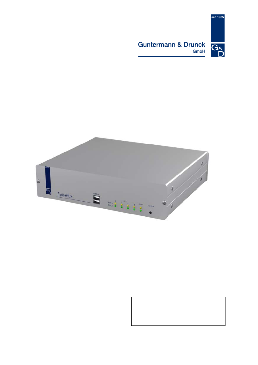
TripleMUX/QuadMUX
Installation & Operating Instructions
Item number: TripleMUX A210 0044
QuadMUX A210 0046
Copyright G&D 2007
06/12/2007 – Version 1.02
Firmware: TM1.04/QM1.02
Subject to errors and alterations
Page 2

Guntermann & Drunck GmbH Installation and operating manual
TripleMUX/QuadMUX
IMPORTANT INFORMATION
Attention
READ THIS OPERATING MANUAL CAREFULLY BEFORE SETTING UP THE DEVICE.
FOLLOW ALL WARNINGS AND OPERATING INSTRUCTIONS FOUND ON THE DEVICE OR IN THE
OPERATING MANUAL
KEEP THE OPERATING MANUAL AT HAND FOR FUTURE USE.
POWER SUPPLY: ONLY OPERATE THIS DEVICE WITH THE SUPPLIED AC ADAPTER OR WITH THE AC
ADAPTER DESCRIBED IN THE OPERATING MANUAL
O
NLY OPERATE THIS DEVICE ON AN EARTHED VOLTAGE SOURCE.
DEENERGISING OF DEVICE: BEFORE INSTALLING THE DEVICE, ENSURE THAT IT IS DEENERGISED.
DISCONNECT THE MAINS PLUG OR POWER SUPPLY FROM THE DEVICE.
T
O DEENERGISE THE DEVICE, UNPLUG THE MAINS PLUG. THEREFORE, PLEASE HEED THE
ACCESSIBILITY OF THE POWER SUPPLY
C
ABLES: ONLY USE CABLES SUPPLIED BY G&D. DAMAGE RESULTING FROM THE USE OF CABLES
NOT SUPPLIED BY
HAZARDS WHEN LAYING CABLES
VENTS: VENTS PREVENT THE DEVICE FROM OVERHEATING. DO NOT COVER THE VENTS.
WARRANTY EXCLUSIONS: G&D PROVIDES NO WARRANTY FOR DEVICES WHICH
-
-
-
G&D
THE USE OF THIS PRODUCT
AREA OF APPLICATION: THE DEVICES ARE DESIGNED FOR INDOOR USE. AVOID EXTREME COLD,
HEAT AND HUMIDITY
CONFORMITY: THE DEVICE CORRESPONDS TO THE ESSENTIAL PROTECTION REQUIREMENTS
AND PROVISIONS OF LAW CONCERNING ELECTROMAGNETIC
COMPATIBILITY (RL 89/336/EWG IN VERSION 2004/108/EG) AS WELL AS THE LOW-VOLTAGE
GUIDELINE
EN55022 (1998) + A1 + A2 CLASS B, EN55024 (1998) + A1 + A2, EN61000-3-2 (2000) + A2,
EN61000-3-3 (1995) + A1+A2, EN60950-1 (2003) AND EN61000-6-2 (2001).
TO REDUCE THE RISK OF ELECTRIC SHOCK, NEVER OPEN THE DEVICE OR
REMOVE ITS COVER
TECHNICIANS
.
G&D IS NOT COVERED BY THE WARRANTY. AVOID CREATING TRIPPING
HAVE BEEN USED FOR ANY PURPOSE OTHER THAN THE INTENDED USE.
HAVE BEEN REPAIRED OR MODIFIED WITHOUT AUTHORISATION.
EXHIBIT MAJOR EXTERNAL DAMAGE THAT WAS NOT REPORTED UPON RECEIPT OF THE
DELIVERY
WERE DAMAGED BY ACCESSORIES NOT SUPPLIED BY G&D.
SHALL NOT BE LIABLE FOR ANY TYPE OF CONSEQUENTIAL DAMAGES THAT MAY ARISE FROM
.
.
.
(RL 73/23, 93/68). THE FOLLOWING STANDARDS WERE USED IN THE ASSESSMENT:
. IF SERVICE IS REQUIRED, PLEASE CONTACT OUR
.
.
.
.
Page 2
Page 3

Guntermann & Drunck GmbH Installation and operating manual
TripleMUX/QuadMUX
Table of contents TripleMUX/QuadMUX
1 Description............................................................................................................. 5
1.1 General information ....................................................................................... 5
1.2 Mode of operation.......................................................................................... 5
1.3 Factory settings / default settings .................................................................. 6
1.4 Master password ........................................................................................... 6
1.5 User password............................................................................................... 6
1.6 Scope of delivery ........................................................................................... 7
2 Installation.............................................................................................................. 9
3 Switching the device on / LED indicators ......................................................... 11
4 System access and operation ............................................................................ 12
4.1 The login window......................................................................................... 12
4.2 Keyboard HotKey switching......................................................................... 13
4.2.1 Default setting......................................................................................... 13
4.2.2 Customer setting .................................................................................... 13
4.3 AdonIS scene switching .............................................................................. 13
4.3.1 Initiating the AdonIS ............................................................................... 13
4.3.2 Operating the AdonIS ............................................................................. 14
4.3.2.1 Keyboard operation ..................................................................14
4.3.2.2 Mouse operation .......................................................................14
4.3.2.3 Display of the scene selected ...................................................15
4.3.3 Position of the scene display .................................................................. 15
5 Function menu..................................................................................................... 16
5.1 Opening the AdonIS function menu............................................................. 16
5.2 The individual functions ............................................................................... 17
5.2.1 AutoScan function .................................................................................. 17
5.2.1.1 Opening the AutoScan function ................................................17
5.2.1.2 Identifying the AutoScan function .............................................17
5.2.1.3 Clearing the AutoScan function ................................................17
5.2.1.4 Setting the AutoScan time ........................................................17
5.2.2 Console setup......................................................................................... 18
5.2.2.1 Setting the AutoScan time ........................................................18
5.2.2.2 Keyboard layout........................................................................18
5.2.2.3 ScreenSaver .............................................................................19
5.2.2.4 Auto logoff.................................................................................19
5.2.2.5 Assigning the console name..................................................... 20
5.2.2.6 Activating the channel display ..................................................20
5.2.2.7 Setting the display position + size ............................................20
5.2.2.8 Setting the menu position / size................................................ 21
5.2.2.9 Setting the Scancode Set .........................................................21
5.2.2.10 AdonIS by mouse .....................................................................21
5.2.2.11 Definition of the first hotkey ......................................................22
5.2.2.12 Activating the double HotKey....................................................22
5.2.2.13 Defining the second key (Scene Key).......................................23
Page 3
Page 4

Guntermann & Drunck GmbH Installation and operating manual
TripleMUX/QuadMUX
5.2.2.14 Setting the QuickAccess ...........................................................23
5.2.2.15 Setting the Accesskey ..............................................................24
5.2.2.16 Changing the user password ....................................................24
5.2.2.17 Changing the master password ................................................25
5.2.2.18 Setting the OpenAccess ...........................................................25
5.2.2.19 Keyboard Type .........................................................................26
5.2.2.20 Restoring the factory settings (Set System Defaults) ...............26
5.2.3 Cascade setup........................................................................................ 27
5.2.4 Setting the video scenes ........................................................................ 28
5.2.4.1 Explanation ...............................................................................28
5.2.4.2 Setting the scene designation...................................................29
5.2.4.3 Modifying the allocation matrix .................................................29
5.2.5 Setting the keyboard/mouse scenes ...................................................... 31
5.2.6 USB Keyboard Mode Setup ................................................................... 32
5.2.7 Logout..................................................................................................... 33
5.2.8 System Info............................................................................................. 33
5.2.9 Mouse Utilities - Utility ............................................................................34
6 Technical data...................................................................................................... 36
Page 4
Page 5
Guntermann & Drunck GmbH Installation and operating manual
TripleMUX/QuadMUX
1 Description
1.1 General information
The TripleMUX and QuadMUX allow you to manage up to four (4) computers
using one keyboard and one mouse, and up to three or four parallel screens.
Each of the 4 computers can be equipped with a Triple or Quad video card. All
four channels on this card can be switched.
The following variants are available (the differences lie in the type of graphics
card fitted in the computer).
As all the products differ only in the type of graphics card in the computer
connected, it is normally the TripleMUX that is being referred to in this manual.
The option for scene switching means that the images from the various video
sources on one or more computers can be switched to the four monitors
connected, according to the user's requirements.
This video scene can be freely assigned the operation of one of the
computers shown.
The TripleMUX therefore makes an active contribution to saving costs, energy
and space for additional peripherals, and to use the computers connected more
efficiently.
A user has easy access to the information provided on multiple computers.
Product Type of graphics card in the computer
TripleMUX
QuadMUX
Triple graphics card
Quad graphics card
1.2 Mode of operation
The TripleMUX is an electronic PC switch, with the following functional
features, among others:
• Full keyboard and mouse emulation for error-free booting of all
computers connected
• Provision of a microprocessor for each channel
• Can be operated on computers with PS/2 and USB mouse
• Full support for the Microsoft Intelli-Mouse
• Video bandwidth up to 400MHz
• Switching (scene selection) via keyboard HotKey or AdonIS
• Freely adjustable scenes
Page 5
Page 6

Guntermann & Drunck GmbH Installation and operating manual
TripleMUX/QuadMUX
• AutoScan function for automatic pass-through of the scenes
• AdonIS can be configured
• System can be secured using password assignment.
1.3 Factory settings / default settings
The TripleMUX is configured as follows with the factory settings:
• No user password assigned,
• Master password permanently set,
• TripleMUX can only be configured via the master password.
1.4 Master password
If you want to make changes to the default settings, enter the master password
in the LOGIN window.
Your master password can be found in Appendix A to the operating manual.
Via the master password you have access to all configuration levels at all
times, regardless of the current settings.
Please ensure that you remove the master password from the operating
manual for your own security.
1.5 User password
There are no in-depth configuration rights assigned to the user password. The
user password is used to avoid unauthorised use of the system.
A user password can only be assigned by the master (see chap. 5.2.2.16).
If a user password is assigned, it must be entered in the LOGIN window.
Page 6
Page 7
Guntermann & Drunck GmbH Installation and operating manual
TripleMUX/QuadMUX
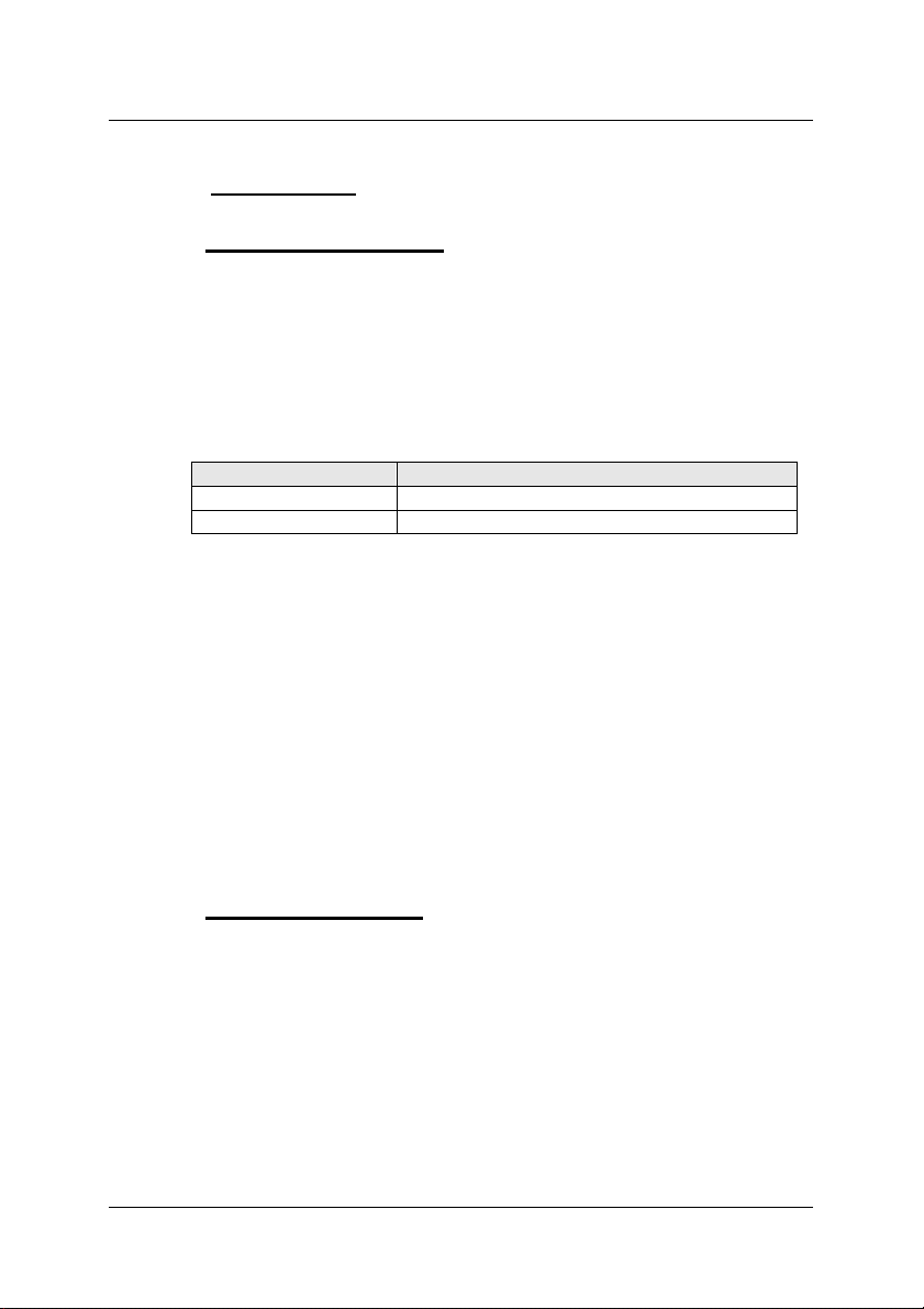
1.6 Scope of delivery
Description Item number
Switch TripleMUX A210 0044
QuadMUX A210 0046
Power supply PowerCable-2 standard A630 0057
Documentation Triple_QuadMUX German version A 910 0080
Triple_QuadMUX English version A 920 0044
In addition to the connection cable required for the product (can be ordered
separately, lengths must be specified when ordering)
Connection cable
comprising
Single connection
cable
CPU-2 VGA + 2 x PS/2 to
CPU-4 VGA + 2 x PS/2 to
CPU-6 VGA + 2 x PS/2 to
CPU-9 VGA + 2 x PS/2 to
CPU-USB-1 VGA, USB to MDR20-M, 1
CPU-USB-2 VGA, USB to MDR20-M, 2
CPU-USB-4 VGA, USB to MDR20-M, 4
Connection cable
set
2 channel (Triple &
QuadMUX)
CPU-MC2-P-4 VGA + 2 x PS/2 to
CPU-MC2-P-6 VGA + 2 x PS/2 to
CPU-MC2-U-2 VGA, USB to MDR20-M, 2
CPU-MC2-U-4 VGA, USB to MDR20-M, 4
CPU-1 VGA + 2 x PS/2 to
MDR20-M, 1 metre
MDR20-M, 2 metres
MDR20-M, 4 metres
MDR20-M, 6 metres
MDR20-M, 9 metres
metres
metres
metres
CPU-MC2-P-2 VGA + 2 x PS/2 to
MDR20-M, 2 metre; plus
1 x VGA-M/M-2
MDR20-M, 4 metre; plus
1 x VGA-M/M-4
MDR20-M, 6 metre; plus
1 x VGA-M/M-6
metres; plus 1 x VGAM/M-2
metres; plus 1 x VGAM/M-4
Item number
A610 0006
A610 0007
A610 0008
A610 0009
A610 0010
A610 0057
A610 0058
A610 0059
A610 0066
A610 0067
A610 0068
A610 0069
A610 0070
Page 7
Page 8
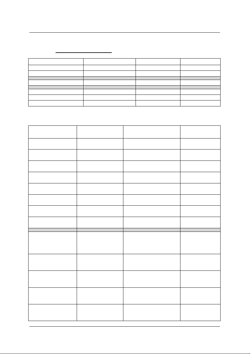
Guntermann & Drunck GmbH Installation and operating manual
Connection cable
set
3 channel (Triple &
QuadMUX)
CPU-MC3-P-4 VGA + 2 x PS/2 to
CPU-MC3-P-6 VGA + 2 x PS/2 to
CPU-MC3-U-2 VGA, USB to MDR20-M, 2
CPU-MC3-U-4 VGA, USB to MDR20-M, 4
Connection cable
set
4 channel (only with
QuadMUX
CPU-MC4-P-4 VGA + 2 x PS/2 to
CPU-MC4-P-6 VGA + 2 x PS/2 to
CPU-MC4-U-2 VGA, USB to MDR20-M, 2
CPU-MC4-U-4 VGA, USB to MDR20-M, 4
CPU-MC3-P-2 VGA + 2 x PS/2 to
CPU-MC4-P-2 VGA + 2 x PS/2 to
TripleMUX/QuadMUX
A610 0072
MDR20-M, 2 metre; plus
2 x VGA-M/M-2
A610 0073
MDR20-M, 4 metre; plus
2 x VGA-M/M-4
A610 0074
MDR20-M, 6 metre; plus
2 x VGA-M/M-6
A610 0075
metres; plus 2 x VGAM/M-2
A610 0076
metres; plus 2 x VGAM/M-4
A610 0077
MDR20-M, 2 metre; plus
3 x VGA-M/M-2
A610 0078
MDR20-M, 4 metre; plus
3 x VGA-M/M-4
A610 0079
MDR20-M, 6 metre; plus
3 x VGA-M/M-6
A610 0080
metres; plus 3 x VGAM/M-2
A610 0081
metres; plus 3 x VGAM/M-4
Page 8
Page 9

Guntermann & Drunck GmbH Installation and operating manual
TripleMUX/QuadMUX
2 Installation
In the basic expansion level, 4 computers can be connected to the TripleMUX.
Each of these computers can be equipped with a triple video card (QuadMUX:
Four-way video card). This procedure will be explained in more detail in this
chapter.
Computer connection:
• Disconnect the monitor, keyboard and mouse cable from the computers.
• Monitor:
Plug the 15 pole Sub HD plug on the CPU-x cable (x=1, 2, 4, 6 or 9
metres) or CPU-USB-x (x= 2 or 4 metres) into the VGA port on computer
1.
Additional monitor connection:
• Connect the VGA-M/M-x connection cable to the other video
channels on the computer.
• Connect the other end of the VGA-M/M-2 cable to the VGA CPU 1.x
– 3.x ports
Please note:
When connecting the graphic cards, ensure that the assignment is
correct on the TripleMUX. As described in chapter 5.2.4.3, due to
physical restrictions not all video sources can be displayed on every
monitor.
• Keyboard/mouse (PS/2):
Now using the two PS/2 plugs of the CPU-x cable, establish the
connection to the keyboard and mouse interface of computer 1. Both
plugs have corresponding symbols on them.
• Alternative keyboard/mouse (USB):
Now using the USB plug of the CPU-USB-x cable, establish the
connection to the keyboard and mouse interface of computer 1.
• Then connect the other end of the CPU-x or CPU-USB-x cable (MDR 20
= Mini Delta Ribbon 20 pole) to the CPU1 port on the TripleMUX.
• To make the connection to the other computers, proceed as described
above
Page 9
Page 10

Guntermann & Drunck GmbH Installation and operating manual
TripleMUX/QuadMUX
Console connection:
• Plug the keyboard and mouse into the corresponding jacks. Connect the
monitor to the Monitor interface on the back of the device.
Additional monitor connection:
Connect the monitors to the MONITOR 2 - 4 jacks.
• Alternatively, you can connect keyboard and mouse via USB. The
relevant connections for this purpose can be found on the front of the
TripleMUX.
Once all the connections to the TripleMUX have been established, switch on the
device.
Page 10
Page 11

Guntermann & Drunck GmbH Installation and operating manual
TripleMUX/QuadMUX
3 Switching the device on / LED indicators
After switching on the device using the rocker switch on the rear, the
TripleMUX initialises the keyboard and mouse. The user LED (green) comes
on immediately after the TripleMUX has been switched on.
The user-LED (yellow) blinks after the device is switched on until a keyboard
(PS/2 or USB) has been found. After successful initialisation of keyboard and
mouse, the user-LED (yellow) changes to a permanent yellow light.
Behaviour of the 4x PC-channel LEDs:
PC-LED below, green:
• After switching the device on, the LED blinks briefly if the channel was
off and then remains off
• After switching the device on, the LED remains permanently lit if the
channel was on, that is, the LED was already lit up and it lights up
further as follows
• lights up permanently as soon as a computer with active power supply
is plugged into this channel
PC-LED above, yellow:
• Goes out after switching on (until it blinks once briefly)
• if you switch to an input channel (via OSD or HotKey), the LED
associated with the channel lights up permanently until you change
the channel.
If one of the connected computers is switched on, the corresponding
channel indicator switches from red to green.
If the initialisation does not occur (red/green blinking does not end), please
check the correct fit of the connection cable (keyboard/mouse) on the user side.
Page 11
Page 12
Guntermann & Drunck GmbH Installation and operating manual
TripleMUX/QuadMUX
4 System access and operation
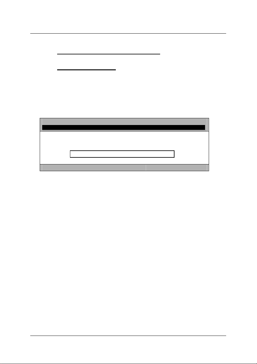
4.1 The login window
If the device is still set to the factory settings (OpenAccess), this window will not
be displayed.
The login window can only be accessed if the free system access
(OpenAccess) has been deactivated.
LOGIN TripleMUX
Please enter your
Password:
max. 12 characters
Esc Enter
In this case, enter your personal user password here. The number of attempts
is unlimited. Confirm your inputs using the ENTER key. ESC cancels the input.
If you want to change the factory settings for the device, enter the master
password (see Appendix A).
In the status on delivery, the SELECT SCENE selection menu will appear
immediately after switching on or entering the password.
SELECT SCENE means that screen scenes are connected up here. These
scenes consist of 3 or 4 different image sources, and these image sources can
originate from one computer or from different computers. For more on this
topic, see chap. 5.2.4.
When the SELECT SCENE menu appears for the first time, the system waits
for the selection of a scene via AdonIS.
In principle, a scene can be selected via keyboard HotKey or via the OSD
(On-Screen-Display) menu.
Page 12
Page 13

Guntermann & Drunck GmbH Installation and operating manual
TripleMUX/QuadMUX
4.2 Keyboard HotKey switching
4.2.1 Default setting
To switch, hold down the CRTL key and then press the NUM key of the
required scene. Permissible keys are the alphanumeric characters above the
letter block from 1 - 8.
Selection of computer 1: CTRL + 1
The default setting begins with 1 and ends with 8.
4.2.2 Customer setting
Both the first and the second key of the HotKey combination can be modified
according to your requirements (see chap. 5.2.2.11 + 5.2.2.13).
If the default setting has been lost or if changes are required, the settings can
be requested from your system administrator.
Master function
4.3 AdonIS scene switching
4.3.1 Initiating the AdonIS
The AdonIS is initiated by holding down the CRTL key and also holding down
the NUM key.
If the you changed the HotKey from the default setting of CRTL (chap.
5.2.2.11), this new HotKey will also be the first key for initiating the AdonIS.
The second key for initiating the AdonIS (NUM), cannot be
The SELECT SCENE window appears on the screen, where 8 possible scenes
will be displayed.
Whether the scene in question assigned to the computer is switched on or off is
indicated by the colour display in the corresponding line in the menu:
green: Computer switched on
red: Computer switched off or port not occupied
changed.
Page 13
Page 14

Guntermann & Drunck GmbH Installation and operating manual
TripleMUX/QuadMUX
4.3.2 Operating the AdonIS
The AdonIS can be operated either using the keyboard or the mouse.
4.3.2.1 Keyboard operation
SELECT SCENE
001 <= Name of the scene, can be edited by
user, max. 14 characters
002 2
003 HotKey number for immediate selection,
=>
can be edited by system administrator
004 4
005 5
006 6
007 7
008 8
Esc Enter F1: Menu
↑ ↓ Select the scene using arrow keys
Enter Triggers the switchover
Esc Cancel without new selection (back)
F1 Open the FUNCTION menu (configuration)
1
3
4.3.2.2 Mouse operation
The AdonIS window can also be operated using the mouse.
Scrolling - Select the PC
left key - Enter
right key - Escape
When using a mouse with three buttons, also:
centre key - F1
This assignment applies to all AdonIS windows.
Page 14
Page 15

Guntermann & Drunck GmbH Installation and operating manual
TripleMUX/QuadMUX
4.3.2.3 Display of the scene selected
If the selection is made using the keyboard or mouse, the name and the
HotKey of the scene selected is displayed permanently on the screen.
001
TripleMUX
The scene is displayed on the monitor(s) which receive an image from a PC on
which the keyboard/mouse pointer is also positioned according to the setting in
the K/M Scene menu.
K/M SCENE TripleMUX
Scene Name A B C D K/M
1 001
The scene is displayed on monitor A, B, C + D.
K/M SCENE TripleMUX
Scene Name A B C D K/M
1 001
The scene is displayed on monitor A only.
If a scene is selected where there is no keyboard/mouse pointer within that
scene on any of the PCs, according to the setting in the K/M Scene menu,
K/M SCENE TripleMUX
Scene Name A B C D K/M
1 001
the scene name is displayed on all monitors.
The scene name can be displayed in red or green:
red: Assigned computer is switched off or channel is unoccupied.
green: Channel is occupied and computer switched on.
The permanent display of the scene can be switched off (see chap. 5.2.2.6).
(scene name, can be edited)
(console name, can be edited)
1 1 1 1 1
1 2 3 4 1
1 2 3 4 -
4.3.3 Position of the scene display
he position of the scene display on the screen can be changed (see chap.
5.2.2.7).
Page 15
Page 16

Guntermann & Drunck GmbH Installation and operating manual
TripleMUX/QuadMUX
5 Function menu
Setup settings and information services are also carried out via the AdonIS.
5.1 Opening the AdonIS function menu
Activate the AdonIS window using the key combination CRTL + NUM.
Press key F1.
From the SELECT SCENE menu, this will take you to the FUNCTION menu:
FUNCTION TripleMUX
F1:
F2:
F3:
F4:
F5:
F6:
F7:
F8:
F9:
Esc Enter
The AdonIS is operated in the same as described in chap. 4.3.2 using the
keyboard and mouse.
There is also the option of using the relevant
F keys to access the required function directly.
The SELECT COMPUTER menu will also take you to the sub-menus or
functions listed in the FUNCTION menu by entering the F keys directly.
SELECT SCENE
AutoScan
Console Setup
Cascade Setup
Video Scene
K/M SCENE
USB Keyboard Mode Setup
Logout
System Info
Utility
Page 16
Page 17

Guntermann & Drunck GmbH Installation and operating manual
TripleMUX/QuadMUX
5.2 The individual functions
Key F1 Back to the SELECT SCENE menu
5.2.1 AutoScan function
Key F2 Triggering the AutoScan function
Activating the AutoScan function causes the automatic interconnection of all
channels.
Even unassigned channels or computers which are switched off can be
included in the AutoScan function (e.g. to check the boot phase).
5.2.1.1 Opening the AutoScan function
Open the AdonIS; key combination (default): CRTL + NUM. You can open the
AutoScan function, as described above, directly from the Select Scene menu,
as well as from the FUNCTION menu.
Then press F 2.
The enabled channels will now be switched to your console in sequence for
approx. 5 seconds. This time period can be changed (see point 5.2.1.4)
5.2.1.2 Identifying the AutoScan function
The activated Scan function is indicated by the "Scan" display.
001 (Scene name, can be edited)
TripleMUX (Console name, can be edited)
Scan ( Active Scan function )
5.2.1.3 Clearing the AutoScan function
In the event of inputs via the keyboard or mouse, the AutoScan function is
paused and is only enabled once again after the final character. The function is
closed by opening the AdonIS (CRTL + NUM) or a scene selection via HotKey.
The Scan display will go out.
5.2.1.4 Setting the AutoScan time
see point 5.2.2.1
Page 17
Page 18

Guntermann & Drunck GmbH Installation and operating manual
TripleMUX/QuadMUX
5.2.2 Console setup
Pressing the F 3 key will take you to the console setup.
CONSOLE SETUP
AutoScan Time: 5 sec.
Keyboard Layout: German
ScreenSaver: Off
AutoLogoff: Off
Console Name: TripleMUX
Display: Temp
Display Position
Menu Position:
Scancode Set: 2
AdonIS by Mouse No
Hotkey: Ctrl
Double Hotkey: No
Scenekey: 1 - 8
Quick Access Yes
Accesskey: F1 – F8
User Password:
Master Password:
Open Access: Yes
Keyboard Type …
Set System Defaults
Esc Enter F1: Save
5.2.2.1 Setting the AutoScan time
Move the cursor to the AutoScan Time row. The existing entry can be
overwritten, or can be edited by pressing the ENTER key.
A scan time of 2 - 60 seconds is permissible. ENTER completes the input
process.
To save the settings, close this menu using F1.
5.2.2.2 Keyboard layout
Adjust the keyboard set used here by TripleMUX to the actual layout of the
keyboard connected. For example, you should change the layout if you notice a
Y/Z reversal (American/German layout).
The following alternatives are available:
• German
• English US
Page 18
Page 19

Guntermann & Drunck GmbH Installation and operating manual
TripleMUX/QuadMUX
• English UK
• French
After moving the cursor to the KEYBOARD LAYOUT field you can use the
SPACE key (toggle) to select the required option.
5.2.2.3 ScreenSaver
The ScreenSaver to be set here is generated by the TripleMUX and bears no
relation to the ScreenSaver on the computer.
As there is normally only an indirect connection (via the TripleMUX) between
the computer and the monitors, you should switch off the computer
ScreenSaver to make your work easier.
The ScreenSaver on the TripleMUX carrys out this task; it switches the monitor
to the power-down mode.
Move the cursor to the ScreenSaver row. The existing entry can be
overwritten, or can be edited by pressing the ENTER key.
A time of 1 - 60 minutes is permissible. The input "0" sets the ScreenSaver to
"OFF".
ENTER completes the entry.
To save the settings, close this menu with F 1.
5.2.2.4 Auto logoff
This setting can be used to activate an automatic LOGOFF from the system.
The automatic LOGOFF takes you back to the LOGIN screen, in the same way
as the manual option (F8 key).
This means that the system is not protected against unauthorised access and
only once the password is entered in the LOGIN window is it possible to access
the computer again (only valid if the OPEN ACCESS has been deactivated).
The time for triggering the automatic LOGOFF is set by moving the cursor to
the Auto Logoff row. The existing entry can be overwritten, or can be edited by
pressing the ENTER key.
A time of 1 - 60 minutes is permissible. Entering "0" switches the logout to
"OFF".
ENTER completes the entry.
To save the settings, close this menu using F 1 .
Page 19
Page 20

Guntermann & Drunck GmbH Installation and operating manual
TripleMUX/QuadMUX
5.2.2.5 Assigning the console name
In the case of a combined use of multiple G&D devices every G&D unit can be
assigned an unique name, the Console Name.
Move the cursor to the Console Name row. The existing entry can be
overwritten, or edited, after the ENTER key is pressed.
The permissible input is 10 alphanumeric characters. ENTER completes the
entry.
To save the settings, close this menu with F 1.
5.2.2.6 Activating the channel display
Here you have the option of setting the display for the selected computer to
either
• Continuous => Yes or
• Temporary => No (disappears after approx. 5 seconds after
.
After moving the cursor to the DISPLAY field you can either use the SPACE
key (toggle) or the keys Y + N to select the required option.
To save the settings, close this menu with F 1.
If you have selected the temporary channel display, you can open the display of
the selected channel at any time using the key combination CRTL + CAPS
LOCK.
^ switch-over)
5.2.2.7 Setting the display position + size
Here you can set the position + size of the channel display on the screen.
Move the cursor to the relevant entry in the Console Setup menu.
Pressing the ENTER key will take you to edit mode and you can then use the
arrow keys or the mouse to move the display to the required point.
+
DISPLAY POSITION
ENTER completes the setting and returns you back to the console setup (saved
temporarily). To save the setting, close the console setup with F 1 (saved
permanently).
Page 20
Page 21

Guntermann & Drunck GmbH Installation and operating manual
TripleMUX/QuadMUX
5.2.2.8 Setting the menu position / size
Change the position and size of all AdonIS windows here. Move the cursor to
the relevant entry in the Console Setup menu.
Pressing the ENTER key will take you to edit mode and you can then use the
arrow keys or the mouse to move the display to the required position.
MENU POSITION TripleMUX
Esc Enter F1:Save
To ensure optimum legibility of the AdonIS at all resolutions, the size of the
display can be changed using the Page up + Page down keys with a monitor
resolution greater than 640 x 480.
ENTER completes the input and takes you back to the Console Setup (saved
temporarily).
To save the settings, close the Console Setup using F1 (saved permanently).
5.2.2.9 Setting the Scancode Set
Note:
To run this function you need to be logged on as a master!
The scancode designates the "language" in which the keyboard communicates
with the computer. The TripleMUX works in scancode 2.
Only carry out this setting in consultation with our service department.
Move the cursor to the relevant entry.
By pressing the SPACE key you can select between the following alternatives:
3 or 2.
5.2.2.10 AdonIS by mouse
Here you can activate the support for the special buttons on the Intelli-Explorer
mouse for working with the TripleMUX. If you set the entry here to "Yes", the
AdonIS, can be opened by pressing button 4 or 5 on the Explorer mouse (left
side buttons) as well as using the keyboard.
Page 21
Page 22

Guntermann & Drunck GmbH Installation and operating manual
TripleMUX/QuadMUX
After moving the cursor to the "AdonIS by Mouse" field, you can use the
SPACE key (toggle) or the buttons Y + N to select the required option.
To save the settings, close the menu using F 1.
5.2.2.11 Definition of the first hotkey
Move the cursor to the HotKey entry.
By pressing the SPACE key you can then select between the following
alternatives:
Ctrl, Alt, AltGr, Win, Shift, AltShift
Please note that the HotKey set here is also used as the first key to
open the AdonIS (e.g. WIN + NUM).
To save the settings, close this menu using F 1.
5.2.2.12 Activating the double HotKey
Here you can specify whether you want to use a double HotKey to open the
AdonIS.
Move step by step using the arrow keys or move the mouse onto the double
Hotkey entry. You can use the Space key to select between the entries
Yes
No (default).
Once you have changes the entry to Yes, the entry in the HotKey row will
change automatically (see chap. 5.2.2.11). You can then select the double
HotKey required in this row. The following positions are available:
Ctrl (Strg) + Shift
Alt +Shift
Alt Gr + Ctrl (Strg)
Windows + Ctrl (Strg)
Shift + Windows
Please note that the HotKey set here is also used as the first button for
opening the AdonIS (e.g. WIN (+CTRL) + NUM).
To save the settings, close this menu using F 1. After this setting, you
need to press a total of three buttons to open the AdonIS or the IVT menu.
Page 22
Page 23

Guntermann & Drunck GmbH Installation and operating manual
TripleMUX/QuadMUX
5.2.2.13 Defining the second key (Scene Key)
The second button on the HotKey for triggering the scene switchover can also
be modified. Proceed in the same way as the process described to change
Hotkey1.
The following alternatives are available, and it is only possible to select groups
of buttons:
• numerical 0 ..9 (default)
• numerical (NUM block) 0 .. 9
• alphabetical A .. K
Once you have made the relevant changes, your new HotKey for scene 2, for
example could look like this: WIN + B.
5.2.2.14 Setting the QuickAccess
Within the scene config (see chap. 5.2.4) there is the option of setting
permanent scenes. Each video scene is also permanently assigned to the
operation of a specific computer with keyboard + mouse.
The QuickAccess function allows you to switch the keyboard and mouse
back and forth freely between the computers shown on the monitors. This
means that the scene does not necessarily have to be closed to be able to
operate another computer. The switchover is carried out by pressing the
Hotkey and at the same time pressing the Accesskey.
Default: CRTL + F1 (to F10)
Move the cursor to the QuickAccess option in the Console Setup menu.
By pressing the SPACE key you can then
enable the QuickAccess: Yes
or block: No (default)
ENTER confirms the change. To save the settings, close this menu using F 1.
Page 23
Page 24

Guntermann & Drunck GmbH Installation and operating manual
TripleMUX/QuadMUX
5.2.2.15 Setting the Accesskey
The actual switchover process in QuickAccess is carried out via the keyboard.
As the default value the F1 – F10 keys are set as Accesskeys. If within a scene
you press the keys CRTL + F 1, the keyboard and mouse will be assigned to
the computer with the screen being displayed via the CPU 1 port on the
TripleMUX. With three monitors this should normally be the left-hand one.
CRTL + F 2 therefore switches the keyboard and mouse to the second monitor,
and CRTL + F 3 to the third monitor. The scene display (see. chap. 5.2.2.6)
also changes at the same time.
If you want to change the default F1- F10, move the cursor onto the Accesskey
option in the CONSOLE SETUP menu.
By pressing the SPACE key you can then switch between the following
alternatives:
NUM 0 – 9 / F1 – F10 / A - K.
ENTER confirms the change. To save the setting, close this menu using F 1.
5.2.2.16 Changing the user password
Note:
To run this function you need to be logged on as a master!
If you want to change the default value (accessed using ENTER) and protect
the TripleMUX with a user password, move the cursor in the Console Setup
menu to the "User Password" field and then press the
ENTER key.
Another menu will appear which prompts you to enter the new password.
CHANGE PASSWORD TripleMUX
Please enter your new
password twice:
[Min. 4, max. 12 characters]
Esc Enter
The cursor is located in the input box and you can enter the password, which
may contain a minimum of 4 and a maximum of 12 characters.
Default: No password.
Page 24
Page 25

Guntermann & Drunck GmbH Installation and operating manual
TripleMUX/QuadMUX
ENTER Cancels the input and goes to the Console Setup menu. The new user
password is saved.
ESC cancels the input without changes.
The changes made here have no effect whatsoever on your master
password.
5.2.2.17 Changing the master password
Note:
To run this function you need to be logged on as a master!
If you want to change the default value according to Appendix A in the manual,
move the cursor in the Console Setup menu onto the "Master Password“ field
and then press the ENTER key.
Another menu will appear which prompts you to enter the new password.
CHANGE PASSWORD TripleMUX
Please enter your new
password twice:
[Min. 4, max. 12 characters]
Esc Enter
Otherwise prompt in the same way as in chap. 5.2.2.16.
5.2.2.18 Setting the OpenAccess
Note:
To run this function you need to be logged on as a master!
With access via OpenAccess anyone can access the TripleMUX and the
connected PCs.
The OpenAccess is defined as follows with the factory settings:
Access to the connected PCs without logging on first with login name
and password
Authorisation to perform the AutoScan
Access to the Console Setup menu (restricted)
Authorisation for manual logout using F8
Authorisation to re-initialise the mouse
Page 25
Page 26

Guntermann & Drunck GmbH Installation and operating manual
TripleMUX/QuadMUX
On delivery, with the factory settings, the access is active for the OpenAccess.
If you want to deactivate this, move the cursor to the OpenAccess entry and
press the SPACE key to select from the following alternatives:
YES: OpenAccess active
NO: OpenAccess deactivated
ENTER confirms the change. To save the setting, close the menu using F 1.
5.2.2.19 Keyboard Type
You can activate the support of the PixelPower keyboard PixelPower Clarity
(blue) with the selection of the menu item Keyboard Type.
This special keyboard enables the operation of the character generator Clarity
of the company PixelPower. The support of this keyboard is deactivated in the
default settings.
Activate this support by pressing SPACE key (toggle function). A yellow “X”
appears behind the entry.
To save the setting, leave this menu by pressing ENTER.
5.2.2.20 Restoring the factory settings (Set System Defaults)
Note:
To run this function you need to be logged on as a master!
Using the function returns the device to the factory settings.
The passwords set will also be reset.
The relevant default settings can be found in the display of the individual
menu windows in this manual.
Using the arrow keys to move step by step to the relevant menu option.
Page 26
Page 27

Guntermann & Drunck GmbH Installation and operating manual
TripleMUX/QuadMUX
Pressing ENTER will run the function and the following info window will be
opened.
Info TripleMUX
This function will delete
all settings.
Press Enter to continue
or
Esc to cancel
Confirm this once more by pressing the ENTER key. The window will change to
the FUNCTION menu.
5.2.3 Cascade setup
Note:
To run this function you need to be logged on as a master!
In the Cascade Setup menu you determine which terminal has been
connected to the four possible PC channels. The following are available:
• PC (default assignment)
• MUX4 (permits the number of computers to be increased to up to 16
computers by using a miniMUX4. However, the access to the multi-way
graphic is only possible on the PCs directly connected to the TripleMUX.
All PCs connected via a miniMUX4 to the TripleMUX transmit only one
graphics signals on the other hand.).
A comprehensive description of cascading the TripleMUX using a miniMUX4 can
be found in the relevant manual.
Open the AdonIS for the TripleMUX using the HotKey combination you have
set or using the default HotKey CRTL + NUM.
In the open AdonIS ("Select Scene" menu) press the F4 key
In the open "Cascade Setup" menu you set for each channel which device is
connected here. The Space key can be used to change the entries. By default
the value here is set to "PC". Pressing the Space key allows you to switch the
entry to "miniMUX 4".
To save your inputs, press the F1 key. This will return you to the Select Scene
menu.
Page 27
Page 28

Guntermann & Drunck GmbH Installation and operating manual
TripleMUX/QuadMUX
5.2.4 Setting the video scenes
5.2.4.1 Explanation
Opening the Video Scene menu will switch the monitors to dark and only the
menu will be visible on the monitors.
In the Video Scene menu you define video scenes to be switched to your
workstation screen. Video scenes are monitor sequences which you can
configure as you wish. In this process you define for which video scene a video
source on a multi-graphic computer is to be switched to a specific monitor on
your workstation.
Open the AdonIS for the TripleMUX using the HotKey combination you have
set or using the default HotKey CRTL + NUM.
In the open AdonIS ("Select Scene" menu), press the F5 key.
In the open window there will be up to eight scenes available.
Video Scene TripleMUX
Scene Name A B C D
1 001
2 002
3 003
4 004
...
8 008
Esc Enter F1: Save
1 1 1 1
2 2 2 2
3 3 3 3
4 4 4 4
4 4 4 4
Column 1: HotKey for immediate selection
Column 2: Scene designation (can be edited; 13 characters)
Column 3: VGA allocation matrix
The menu displayed reflects the default setting. Four computers, each with 1
quad video card has been assumed here. The three pieces of image
information per computer are placed 1:1 on the video outputs A, B, C + D of the
TripleMUX.
Example scene 1 (equivalent to default scene 1)
Hot Scene Name A B C D
1 001
1 1 1 1
Scene key for this scene: 1
Scene designation: 001
Image on monitor A: A1 from TripleMUX = CPU 1 from PC1
Image on monitor B: B1 from TripleMUX = VGA CPU 1.2 from PC1
Image on monitor C: C1 from TripleMUX = VGA CPU 1.3 from PC1
Image on monitor D: D1 from TripleMUX = VGA CPU 1.4 from PC1
Page 28
Page 29

Guntermann & Drunck GmbH Installation and operating manual
Example scene 2 (not based on default setting)
TripleMUX/QuadMUX
Naturally the scenes can also be adapted to your requirements. Example 2
shows an adapted scene based on the connection schematic on this page.
Please contact your system administrator for modifications.
Hot Scene Name A B C D
6 a1b2c4 PC4
1 1 2 4
Scene key for this scene: 6
Scene designation: a1b2c4 PC4
Image on monitor A: A1 from TripleMUX = CPU 1 from PC1
Image on monitor B: B1 from TripleMUX = VGA CPU 1.2 from PC1
Image on monitor C: C2 from TripleMUX = VGA CPU 2.2 from PC2
Image on monitor D: D4 from TripleMUX = VGA CPU 4.3 from PC4
5.2.4.2 Setting the scene designation
Select the field to be edited using the arrow keys or using the mouse. If you
want to rename the scene, the previous entry can simply be overwritten.
Pressing the SPACE key will take you to the edit mode for this field.
Enter the scene designation using the letter block or the number keys above
the letter block. It is not possible to enter special characters.
ENTER completes the input process and automatically goes to the next scene
designation.
Other fields in the Video Scene menu can only be changed by the
master.
To save the settings, close the menu using F1.
5.2.4.3 Modifying the allocation matrix
Note:
To run this function you need to be logged on as a master!
In addition to the change of scene designation which every user can carry out,
the video combinations and computer assignments allocated to the scenes
can also be changed by the master.
It is important to bear this point in mind during the installation process as
due to physical limitations not every video source can be displayed on every
monitor (see explanation below).
Page 29
Page 30

Guntermann & Drunck GmbH Installation and operating manual
TripleMUX/QuadMUX
Select the field to be edited using the arrow keys or using the mouse, after you
have logged onto the system using the master password.
The master can also edit the greyed out fields as well:
Hot Scene Name A B C D
1 001
The previous entry can simply be overwritten.
1 1 1 1
Based on the connection diagram shown above, an edited Video Scene menu
is given below with explanations of the changes resulting from this.
Video Scene TripleMUX
Scene Name A B C D
1 a1b1c1PC1
2 a3b3c3PC3
3 a3b2c4PC2
4 a3b1c1PC3
...
8 008
1 1 1 1
2 2 2 2
3 3 3 3
4 4 4 4
4 4 4 4
Esc Enter F1: Save
This setting gives the following:
A B C D
1 1 1 1
3 3 3 3
3 2 4 2
Image from PC 1 on monitor A,B,C
as before, but with PC3
Monitor A = image V3.1 from PC3
Monitor B = image V2.2 from PC2
Monitor C = image V4.3 from PC4
Monitor D = image V2.4 from PC2
3 1 1 2
Monitor A = image V3.1 from PC3
Monitor B = image V1.2 from PC1
Monitor C = image V1.3 from PC1
Monitor D = image V2.4 from PC2
The table shows that only ever one PC used for operation is included
in a scene if it is visible on at least one monitor.
This procedure should still be followed to prevent accidental inputs on
computers which are not visible.
The HotKeys assigned to the scenes cannot be changed in the SCENE
CONFIG menu. If you want to use another group of HotKeys, open the
Console Setup menu (see chap. 5.2.2.13)
To save the settings, close the menu using F1.
Page 30
Page 31

Guntermann & Drunck GmbH Installation and operating manual
TripleMUX/QuadMUX
5.2.5 Setting the keyboard/mouse scenes
In the keyboard/mouse menu you can define where the keyboard/mouse
pointer is to be located in an activated video scene. This is because with a
scene up to max. three different multi-graphic computers can distribute one (or
more) VGA signals onto the three workstation monitors with a TripleMUX. This
will have been defined as a video scene, as defined in chap. 5.2.4. In this
menu you specify the computer on which the keyboard and mouse is to be
active during the selected video scene.
K/M SCENE TripleMUX
Scene Name A B C D K/M
1 001
2 002
3 003
4 004
…
8 008
ESC Enter F1: Save
The entries in the VGA columns (A, B, C & D) are transferred from the settings
from the "Video Scene" menu.
The column "K/M." is used to specify on which of the connected computers the
keyboard/mouse pointer is to be located within a video scene.
If in this you position the cursor using the arrow keys or using the mouse in the
"K/M" column, you can enter a numerical value of 1 to 4 (according to the
possible PC channels on the TripleMUX). This definition will call up the
computer defined here on the TripleMUX when the required video scene is
opened. At the same time, this computer will have the keyboard/mouse pointer.
In the example menu shown above, the definition has been set in scene "003"
that channel 4 is to be operated on the TripleMUX and has the
keyboard/mouse pointer.
To save the settings, close the menu using F1.
1 1 1 1 1
1 2 4 3 3
2 2 4 4 4
3 1 2 4 2
1 1 3 1 1
Page 31
Page 32

Guntermann & Drunck GmbH Installation and operating manual
TripleMUX/QuadMUX
5.2.6 USB Keyboard Mode Setup
Important: The setup of the USB keyboard mode can only be selected within
the AdonIS of the master device. This setup is not available, if the
TripleMUX is operated as a slave within a cascade.
In this case, temporarily operate the TripleMUX as a master
device and change the setup of the USB keyboard mode.
Recent standard keyboards are usually provided with 105 keys. Several
manufacturers of USB keyboards expand the number of the keys. Special
functions of the computer can be operated through the additional keys.
The following models are counted among the expanded USB keyboards:
The multimedia keyboard of the Apple Mac minis provided with a special key
to open the DVD drive.
The keyboards of Sun desktops and servers have separate keys to operate
the special system functions.
Besides these examples, further keyboards are available at the market that
enable the operation of the special functions of the computer through keys. The
TripleMUX supports the following types of USB keyboards:
PC Multimedia: USB keyboard with additional multimedia keys
PC Standard: standard USB keyboard
SUN German: German USB keyboard for Sun desktops and Sun servers
SUN US: American USB keyboard for Sun desktops and Sun servers
Hint: The setup of the keyboard layout of Sun desktops and Sun servers is
carried out during the booting. Therefore, a reboot of the Sun desktops
and the Sun servers is required after the activation of the keyboard
mode SUN German or the keyboard mode SUN US.
In the default settings of the TripleMUX, the USB Keyboard Mode "PC
Multimedia" is active on all channels:
USB KEYBOARD MODE TripleMUX
Channel Mode
1
2
3
4
PC Multimedia
PC Multimedia
PC Multimedia
PC Multimedia
ESC Space:Change F1: Save
Page 32
Page 33

Guntermann & Drunck GmbH Installation and operating manual
TripleMUX/QuadMUX
To change the USB Keyboard Mode of a channel, select this channel with the
arrow keys. By pressing the SPACE key you can switch between the different
keyboard modes.
To save the settings, leave the menu by pressing F1.
5.2.7 Logout
This function cancels the assignment to a selected scene and your session
logged onto TripleMUX. You will only be able to access the system again
once you have entered your user password or the master password.
Using this function means that the input screen for the password will appear
when the F 8 key is pressed.
LOGIN TripleMUX
Please enter your
Password:
max. 12 characters
Esc Enter
You can also use this function by going to the relevant option in the Function
menu using the arrow keys or the mouse and then pressing the ENTER key.
You should only ever use this function if you want to protect your
computer against unauthorised access, e.g. when you leave your
workstation.
5.2.8 System Info
The System Info window, which is opened using the F 9 key, cannot be used
to make settings at all. Here you will instead find information on the TripleMUX
which is relevant for site service staff.
ESC closes this window.
Page 33
Page 34

Guntermann & Drunck GmbH Installation and operating manual
TripleMUX/QuadMUX
5.2.9 Mouse Utilities - Utility
If the mouse on one computer is no longer functioning during operation
(mouse pointer isn't moving), there is the option of performing a re-initialisation.
First check that all the connection cables are correctly connected. Please note
that a mouse enable is only carried out for the active channel in question
(PC1 to PC4).
Using AdonIS to switch to this computer and press the F 1 key. This will take
you to the FUNCTION menu.
Use the arrow keys to move step by step in the menu section under F10 to the
Mouse Utility menu option.
Pressing ENTER will open up a sub-menu providing the following options:
UTILITY TripleMUX
►►Read manual for details◄◄
Enable Mouse
Enable Intelli
Enable Int Explorer
Reset Mouse
Esc Enter
Caution! Only carry out the appropriate
Enable/Reset for the individual computer!
Enable Mouse (standard mouse)
Use this function with non-Windows systems (e.g. Linux) if the computer is
working with a standard mouse driver.
Enable Intelli (MS IntelliMouse)
Use this function with non-Windows systems (e.g. Linux) if the connected
computer has the MS IntelliMouse driver loaded on it.
Enable Int Explorer (MS IntelliMouse)
Use this function with non-Windows systems (e.g. Linux) if the connected
computer has the MS Intelli Explorer mouse driver loaded.
Page 34
Page 35

Guntermann & Drunck GmbH Installation and operating manual
TripleMUX/QuadMUX
Reset Mouse
Select function for Windows operating systems; regardless of the mouse
driver set.
This applies to:
WIN 98, WIN NT, WIN ME, WIN 2000, WIN XP.
Move the cursor to the relevant option using the arrow keys.
Press the ENTER key.
The mouse is initialised and the menu closed. The mouse will be working again
with full functionality.
Page 35
Page 36

Guntermann & Drunck GmbH Installation and operating manual
TripleMUX/QuadMUX
6 Technical data
Video
• Format: VGA (analogue)
• Resolution: from 640 x 350 @120 Hz to 1920 x 1440 @ 60 Hz
• Video bandwidth: up to 400 MHz
• H/V-Sync: 135KHz/150Hz
• Transmittable signals: RGBHV, RGsB, RsGsBs, RGBc
Keyboard / mouse
(ON COMPUTER + USER SIDE)
•
•
Interfaces
• Console-side : 2 x 6-pin miniDIN-F for keyboard and mouse
• Computer-side : 4 x 20-pin MDR-M
4 x (2) x 15 pole SUB-HD-M for monitor connection
Switching:
Via keyboard inputs (HotKey), SCAN function or OSD.
Computer-side
- direct: PS/2, USB, MAC USB, RS 6000, HP 9000, SGI,
DEC Alpha Station, Open Bloomberg
- via converter: SUN, SUN-USB, MAC via computer-side converter
(mixed operation possible)
User-side
- direct: PS/2, USB, MAC USB, RS 6000, HP 9000, SGI,
DEC Alpha Station, Open Bloomberg
- via converter: SUN, SUN-USB via user-side converter
(mixed operation possible)
2 x USB-A for keyboard and mouse (front side)
3 x 15 pole SUB-HD-M for monitor connection
(TripleMUX) or
4 x 15 pole SUB-HD-M for monitor connection
(QuadMUX) or
(TripleMUX) or
4 x (3) x 15 pole SUB-HD-M for monitor connection
(QuadMUX) or
Page 36
Page 37

Guntermann & Drunck GmbH Installation and operating manual
TripleMUX/QuadMUX
Housing dimensions (W x H x D in mm)
Desktop 19" variant
TripleMUX 270 x 88 x 210 19" x 2 HU x 210
QuadMUX 270 x 88 x 210 19" x 2 HU x 210
Power supply:
TripleMUX: 100 – 240 V primary, 60 – 50 Hz, 205 - 95 mA
QuadMUX: 100 – 240 V primary, 60 – 50 Hz, 235 - 105 mA
Power consumption (operation)
:
TripleMUX: 100 VAC = 11.0W / 240VAC = 11.4W
QuadMUX: 100 VAC = 12.8W / 240VAC = 13.2W
Temperature ranges
:
• Operation: 5 to 40° C rel. humidity < 80%, non-condensing
• Storage: -10 to 55° C rel. humidity < 85%, non-condensing
Options:
Cascading of the system by using a miniMUX4
Page 37
Page 38

Guntermann & Drunck GmbH Installation and operating manual
TripleMUX/QuadMUX
Appendix:
Your master password is:
Please ensure that you remove this appendix from the operating manual!
4658
Page 38
Page 39

Guntermann & Drunck GmbH Installation and operating manual
TripleMUX/QuadMUX
Page 39
Page 40

Guntermann & Drunck GmbH
System Development,
Germany
Dortmunder Str. 4a ▪ Tel: +49-2739/8901-100
57234 Wilnsdorf, Germany ▪ Fax: +49-
2739/8901-120
©Sun, MAC, RS 6000, HP 9000, SGI, DEC Alpha Station, USB are registered trademarks of the
relevant manufacturers.
Page 40
 Loading...