

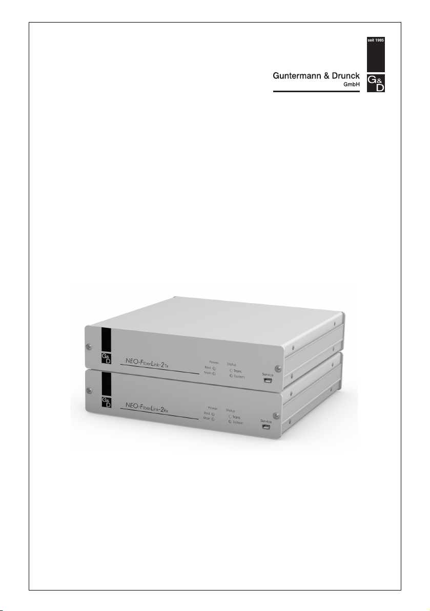
NEO-FiberLink-2
Installation Guide

About this manual
This manual has been carefully compiled and examined to the state-of-the-art.
G&D neither explicitly nor implicitly takes guarantee or responsibility for the qual-
ity, efficiency and marketability of the prod
differs from the scope of service covered by this manual.
For damages which directly or indirectly result
as for incidental damages or consequential damages, G&D is liable only in cases of
intent or gross negligence.
uct when used for a certain purpose that
from the use of this manual as well
Caveat Emptor
G&D will not provide warranty for devices that:
Are not used as intended.
Are repaired or modified by unauthorized personnel.
Show severe external damages that was not
Have been damaged by non G&D accessories.
G&D will
the products.
not be liable for any consequential damages that could occur from using
reported on the receipt of goods.
Proof of trademark
All product and company names mentioned in this manual, and other documents
you have received alongside your G&D product, are trademarks or registered trademarks of the holder of rights.
© Guntermann & Drunck GmbH 2010. All rights reserved.
Version 1.00 – 20/12/2010
Firmware: 1.0.000 (01893)
Guntermann & Drunck GmbH
Dortmunder Str. 4a
57234 Wilnsdorf
Germany
Phone +49 (0) 2739 8901-100
Fax +49 (0) 2739 8901-120
http://www.GDsys.de
sales@GDsys.de
i · NEO-FiberLink-2

Contents
Table of Contents
Safety guidelines ............................................................................................... 1
Introduction ..................................................................................................... 3
Package contents .............................................................................................. 3
Installation ....................................................................................................... 5
Connecting the transmitter module (NEO-FiberLink-2Tx)
Connecting the receiver module (NEO-FiberLink-2Rx) .......................................... 6
Start-up ............................................................................................................ 6
Status displays .................................................................................................. 7
Transmitter module (NEO-FiberLink-2Tx) ......................................................... 7
Front panel .................................................................................................. 7
Back panel ................................................................................................... 8
Receiver module (NEO-FiberLink-2Rx) ............................................................. 9
Front panel .................................................................................................. 9
Back panel ................................................................................................. 10
Technical data ................................................................................................ 11
.................................. 5
NEO-FiberLink-2 · 1

Safety guidelines
Safety guidelines
Please read the following safety guidelines attentively before you start running the
G&D product. The guidelines help avoid damage to the product and prevent possible injuries.
All persons using this equipment must be informed about these safety guidelines.
Observe all warnings or operating instructions put on the device or stated in this
operating guide.
, Avoid
, Disconnect the main powe
, Ensure con
! Do not cover the ventilation openings
! Avoid
! Only use a grounded electrical outlet
! U
! Operate
the risk of electric shock
To avoid the risk of electric shock, do not open the devi
If service is required, please contact our technicians.
r plug or the power supply before installation
Before installation, ensure that the device ha
source. Disconnect the main power plug or the power supply of the device.
stant access to the power plugs
Ensure during the installation of the devices that the power plugs remain accessible.
Ventilation openings prevent the device from overheating. Do not cover them.
the risk of tripping over cables
Ensure that there is no risk of tripping over cables.
Operate this device by using a grounded electrical outlet.
se only the provided G&D power pack
Operate this device with the provided G&D power pack or with the power packs
listed in the operating manual.
the device only in the intended area of application
This device has been designed for indoor u
heat or humidity.
s been disconnected from the power
se. Do not expose it to extreme cold,
ce or remove the covers.
1 · NEO-FiberLink-2

Safety guidelines
LASER CLASS 1
DIN EN 60825-1:2001-11
Complies with 21 CFR
1040.10 and 1040.11
Class 1 Laser Product
Special advices for dealing with laser technology
The devices of the NEO-FiberLink series use components with laser technology
which comply with laser class 1.
They meet the requirements according to DIN EN 6
well as U.S. CFR 1040.10 and 1040.11.
Mind the following advices when dealing with laser beams:
! Avoid eye contact with laser beam
Although class 1 laser are considered nonhaza
be avoided. Do not stare into the beam or view directly with optical instruments.
! Always conne
ct optical connections or cover them with protection caps
Optical connections of the Transmission socket as well as cable plugs must always
be covered with a
! Only use G&D
connector or a protection cap.
certified transmission modules
It is not allowed to use transmission mod
class 1 according to DIN EN 60825-1:2001-11. By ap
compliance of the given instructions and recommendations for laser safety cannot be guaranteed.
The guarantee of complying with all relevant instructions can only be given by
applying original components. The devices must therefore ony be operated
G&D certified transmission modules.
0825-1:2001-11, IEC 60825-1 as
rdous, direct eye contact should
ules that do not comply with laser
plying such modules, the
NEO-FiberLink-2 · 2

Introduction
Introduction
The transmitter and the receiver module of the NEO-FiberLink series increase the
range between two matrix switches (CATCenter NEO)
to 10,000 metres. The data between the two modules is transmitted via two singlemode fibre optics.
For each NEO-FiberLink system two CPU ports of the master matrix switch are connected to two CON ports of the sl
ously access the computers connected to
Both transmitter and receiver module can either be placed between the master and
the slave matrix switch (cascade level 1) or between the slave matrix switches of the
second cascade level.
The figure on the right-hand side shows how to place the transmitter and receiver
module of the NEO-FiberLink series between two matrix switches.
ave matrix switch. Now two users can simultane-
the slave matrix switch.
within a matrix system to up
Package contents
1 × transmitter module (NEO-FiberLink-2Tx)
1 × receiver module (NEO
2 × power cable (PowerCab
1 × service cable (USB-Serv
1 × manual
NOTE:
The package contents of device variants for rack mounting also contain a
rack mount set.
-FiberLink-2Rx)
le-2 Standard)
ice-2)
3 · NEO-FiberLink-2

Master
.
.
Slave
.
Package contents
NEO-FiberLink-2 · 4

Installation
Transmission-2 CATTransmission-1 CAT
to slave / lower-level device
Main Power
Red. Power
Class 1 Laser Product
Rx
Tx
Transmission Fiber
Installation
The transmitter and receiver module can either be placed between the master and
the slave matrix switch (cascade level 1) or between the slave matrix switches of the
second cascade level.
ADVICE:
Basic information regarding the cascading of a matrix switch is given in
the chapter Installing the expansion unit of the matrix switches’ installation manual.
Connecting the transmitter module (NEO-FiberLink-2Tx)
Place the transmitter module close to the slave matrix switch.
Transmission – Tx: Insert the LC plug of the fibre optics, which is available as acces-
sory. Connect the other end of the cable to the Trans
receiver module.
Transmission – Rx: Insert the LC plug of the fibre optics, which is available as acces-
sory. Connect the other end of the cable to the Tran
receiver module.
Transmission-1 CAT: Use a CAT5 (or better) twisted pair cable to connect these inter-
faces to one of the CON
interfaces of the slave matrix switch.
Transmission-2 CAT: Use a CAT5 (or better) twisted pair cable to connect these inter-
faces to one of the CON
interfaces of the slave matrix switch.
Red. Power: If necessary, connect the connection cable of the optional power pack to
this interface. Then connect a power cable to the power pack and a power outlet.
Main Power: Insert the supplied power cable and connect it to a power outlet.
mission – Rx interface of the
smission – Tx interface of the
5 · NEO-FiberLink-2

Start-up
Main Power
Red. Power
Transmission-1 CAT Transmission-2 CAT
to master / higher-level device
Rx
Tx
Transmission Fiber
Class 1 Laser Product
Connecting the receiver module (NEO-FiberLink-2Rx)
Place the receiver module close to the slave matrix switch.
Transmission – Tx: Insert the LC plug of the fibre optics, which is available as acces-
sory. Connect the other end of the cable to the Trans
receiver module.
Transmission – Rx: Insert the LC plug of the fibre optics, which is available as acces-
sory. Connect the other end of the cable to the Tran
receiver module.
Transmission-1 CAT: Use a CAT5 (or better) twisted pair cable to connect these inter-
faces to a CP
U interface of the master matrix switch.
Transmission-2 CAT: Use a CAT5 (or better) twisted pair cable to connect these inter-
faces to a CP
U interface of the master matrix switch.
Red. Power: If necessary, connect the connection cable of the optional power pack to
this interface. Then connect a power cable to the power pack and a power outlet.
Main Power: Insert the supplied power cable and connect it to a power outlet.
mission – Rx interface of the
smission – Tx interface of the
Start-up
Turn on the master and the slave matrix switch as well as the transceiver and
receiver module of the NEO-FiberLink series.
NEO-FiberLink-2 · 6

Status displays
Main
Red.
Power
ServiceStatus
Trans.
System
Transmission-2 CATTransmission-1 CAT
to slave / lower-level device
Main Power
Red. Power
Class 1 Laser Product
Rx
Tx
Transmission Fiber
Status displays
Both the transmitter and the receiver module provide different LEDs.
The LEDs on the front panel allow you to control the modules’ operating status at
any time
The Tran
LEDs that inform the user about the data connections.
Transmitter module (NEO-FiberLink-2Tx)
smission interfaces at the back panels of the modules provide additional
Front panel
Section LED Status Meaning
Power Red. on The optional power pack is connected and supplies the
Status Trans. on Working data connection between transmitter and
7 · NEO-FiberLink-2
required voltage.
off The optional power pack is not connected, or the
connection to the mains could not be established.
Main. on The power pack is turned on and supplies the required
voltage.
off The power pack is not connected, or the connection to
the mains could not be established.
receiver module.
off Interrupted data connection be
tween transmitter and
receiver module
System blinking The transceiver module is ready for operation.
off The transceiver module is turned off.

Back panel
Section LED Status Meaning
Trans. 1 CAT yellow on The video signal is transmitted.
off No video signal is transmitted.
green on Working data connection between transmitter and
receiver module. Master and slave matrix switch are
connected.
blinking Working data connection between transmitter and
receiver module. Master or slave matrix switch
connected.
Interrupted data connection between transmitter and
receiver module
off Working data connection between transmitter and
receiver module. Neither a master nor a slave matrix
switch is connected.
Trans. 2 CAT yellow on The video signal is transmitted.
off No video signal is transmitted.
green on Working data connection between transmitter and
receiver module. Master and slave matrix switch are
connected.
blinking Working data connection between transmitter and
receiver module. Master or slave matrix switch
connected.
off Working data connection between transmitter and
receiver module. Neither a master nor a slave matrix
switch is connected.
Status displays
are not
are not
NEO-FiberLink-2 · 8

Status displays
Main
Red.
Power
ServiceStatus
Trans.
System
Main Power
Red. Power
Transmission-1 CAT Transmission-2 CAT
to master / higher-level device
Rx
Tx
Transmission Fiber
Class 1 Laser Product
Receiver module (NEO-FiberLink-2Rx)
Front panel
Section LED Status Meaning
Power Red. on The optional power pack is connected and supplies the
off The optional power pack is not connected, or the
Main. on The power pack is turned on and supplies the required
off The power pack is not connected, or the connection to
Status Trans. on Working data connection between transmitter and
off Interrupted data connection be
System blinking The transceiver module is ready for operation.
off The transceiver module is turned off.
required voltage.
connection to the mains could not be established.
voltage.
the mains could not be established.
receiver module.
tween transmitter and
receiver module
9 · NEO-FiberLink-2

Back panel
Section LED Status Meaning
Trans. 1 CAT yellow on The video signal is transmitted.
off No video signal is transmitted.
green on Working data connection between transmitter and
receiver module. Master and slave matrix switch are
connected.
blinking Working data connection between transmitter and
receiver module. Master or slave matrix switch
connected.
off Working data connection between transmitter and
receiver module. Neither a master nor a slave matrix
switch is connected.
Trans. 2 CAT yellow on The video signal is transmitted.
off No video signal is transmitted.
green on Working data connection between transmitter and
receiver module. Master and slave matrix switch are
connected.
blinking Working data connection between transmitter and
receiver module. Master and slave matrix switch are not
connected.
off Working data connection between transmitter and
receiver module. There is only on
connected or neither a master nor a slave matrix switch
is connected.
The data connection between
module was interrupted.
Status displays
are not
e master matrix switch
transmitter and receiver
NEO-FiberLink-2 · 10

Technical data
Technical data
GENERAL FEATURES OF THE NEO-FIBERLINK SERIES
Video Resolution @ 60 Hz: max. 1920 × 1200 pixels
Video bandwidth: 180 MHz
Vertical frequency: 50 Hz to 180 Hz
Horizontal frequency: 30 kHz to 130 kHz
Audio Resolution: 24 bits
Refresh rate: 48 kHz
Bandwidth: 22 kHz
Data transmission
between m
Main power supply Type: internal power pack
Redundant
power supply
optional
Housing Material: anodised aluminium
Operational environment
Conformity CE, RoHS
odules:
Interface: 1 × LC-Duplex socket
Transmission distance:
Connection: 1 × IEC plug (IEC-320 C14)
Type: external power pack
Connection: 1 × Mini-DIN 4 socket (Power In)
Dimensions (W × H × D): 210 × 1 U × 210 mm
Weight: approx. 1,2 kg
Temperature: +5 to +40 °C
Air humidity: < 85%, non-condensing
max. 10,000 metres
TRANSMITTER MODULE | NEO-FIBERLINK-2TX
Interfaces Connection of the master
matrix switch:
Connection of the
receiver module:
Power consumption Main power supply: 100 - 240 VAC/60 - 50 Hz; 0,4 - 0,2 A
Redundant power supply: 12 VDC; 1.4 A
RECEIVER MODULE | NEO-FIBERLINK-2RX
Interfaces Connection of the slave
matrix switch:
Connection of the
transmitter module:
Power consumption Main power supply: 100 - 240 VAC/60 - 50 Hz; 0,3 - 0,2 A
Redundant power supply: 12 VDC; 1,1 A
11 · NEO-FiberLink-2
2 × RJ45 interface
1 × LC-Duplex socket
2 × RJ45 interface
1 × LC-Duplex socket

Notes
NEO-FiberLink-2 · 12

Guntermann & Drunck GmbH
Dortmunder Str. 4a
57234 Wilnsdorf
Germany
Phone +49 2739 8901-100
Fax +49 2739 8901-120
http://www.GDsys.de
sales@GDsys.de
A9200116
 Loading...