

Guntermann & Drunck GmbH
www.gdsys.de
G&D DVICenter
EN
Web Application »Config Panel«
Configuring the matrix switch
A9200106-2.02

About this manual
This manual has been carefully compiled and examined to the state-of-the-art.
G&D neither explicitly nor implicitly takes guarantee or responsibility for the quality, efficiency and marketability of the product when used for a certain purpose that
differs from the scope of service covered by this manual.
For damages which directly or indirectly result from the use of this manual as well
as for incidental damages or consequential damages, G&D is liable only in cases of
intent or gross negligence.
Caveat Emptor
G&D will not provide warranty for devices that:
Are not used as intended.
Are repaired or modified by unauthorized personnel.
Show severe external damages that was not reported on the receipt of goods.
Have been damaged by non G&D accessories.
G&D will not be liable for any consequential damages that could occur from using
the products.
Proof of trademark
All product and company names mentioned in this manual, and other documents
you have received alongside your G&D product, are trademarks or registered trade
marks of the holder of rights.
Imprint
© Guntermann & Drunck GmbH 2014. All rights reserved.
Version 2.02 – 10/12/2014
Version: 1.11.7
Guntermann & Drunck GmbH
Dortmunder Str. 4a
57234 Wilnsdorf
Germany
Phone +49 2739 8901-100
Fax +49 2739 8901-120
http://www.GDsys.de
sales@GDsys.de
-
i · G&D DVICenter

Contents
Table of contents
Chapter 1: Basic functions
System requirements ....................................................................................... 10
Supported web browsers .................................................................................. 10
Java Runtime Environment ............................................................................. 10
Configuring the network settings ................................................................... 11
Getting started ................................................................................................ 12
Starting the web application ............................................................................. 12
Security instructions of the web browser ........................................................... 12
User login at the web application ..................................................................... 13
Operating the web application .......................................................................... 13
User interface .............................................................................................. 13
Frequently used buttons ............................................................................... 15
User logout ...................................................................................................... 15
Selecting the default language of the web application ........................................ 16
Selecting the hash algorithm for storing passwords ............................................ 16
Showing the version number of the web application .......................................... 16
Port administration .......................................................................................... 17
Automatic port mode................................................................................... 17
Compatibility mode ..................................................................................... 18
Configuring ports......................................................................................... 19
Showing ports modes ................................................................................... 20
Basic configuration of the web application ..................................................... 21
Network settings .............................................................................................. 21
Configuring the network settings .................................................................. 21
Configuring the global network settings ........................................................ 22
Increasing the reliability of network connections through link aggregation ..... 23
Reading out the status of the network interfaces ............................................ 25
Creating and administrating netfilter rules ........................................................ 25
Creating new netfilter rules........................................................................... 25
Editing existing netfilter rules ....................................................................... 26
Deleting existing netfilter rules ..................................................................... 28
Changing the order/priority of existing netfilter rules .................................... 28
Creating an SSL certificate ............................................................................... 29
Special features for complex KVM systems ................................................... 29
Creating a Certificate Authority.................................................................... 29
Creating any certificate ................................................................................ 30
Creating and signing the X509 certificate ...................................................... 31
Creating a PEM file ..................................................................................... 32
Selecting an SSL certificate .............................................................................. 32
Firmware update ............................................................................................. 33
Restoring the default settings ............................................................................ 34
G&D DVICenter · 1

Contents
Network functions of the devices .................................................................... 35
NTP server ...................................................................................................... 35
Time sync with an NTP server......................................................................35
Setting time and date manually .....................................................................36
Logging syslog messages .................................................................................. 37
Locally logging the syslog messages ..............................................................37
Sending syslog messages to a server ..............................................................38
Viewing and saving local syslog messages .....................................................39
User authentication with directory services ....................................................... 40
Monitoring functions ...................................................................................... 42
Viewing monitoring values ............................................................................... 43
Listing values by applying monitoring sets ....................................................43
Listing individual values of critical devices ....................................................43
Disabling monitoring values ............................................................................. 43
Advanced function regarding the administration of critical devices ................... 44
Messages regarding critical statuses of devices ...............................................44
Viewing the list of critical devices..................................................................44
Marking messages from critical devices as read..............................................45
Administrating monitor groups ......................................................................... 45
Adding monitoring groups............................................................................46
Changing name and/or comment of monitoring groups.................................46
Assigning members to monitoring groups......................................................46
Duplicating monitoring groups .....................................................................47
Deleting monitoring groups ..........................................................................47
Administrating monitoring sets ......................................................................... 48
Adding monitoring sets ................................................................................48
Changing name and/or comment of monitoring sets .....................................48
Assigning members to monitoring sets ..........................................................49
Selecting a monitoring set in the folder configuration.....................................49
Duplicating monitoring sets ..........................................................................50
Deleting monitoring sets...............................................................................50
Device monitoring via SNMP ......................................................................... 51
Practical use of the SNMP protocol .................................................................. 51
Configuring the SNMP agent ........................................................................... 51
Configuring SNMP traps .................................................................................. 53
Logbook .......................................................................................................... 56
The dialogue entries of the logbook ................................................................... 56
The »Logbook configuration« window ..........................................................56
Viewing a logbook entry in detail ..................................................................57
Basic logbook functions .................................................................................... 57
Creating a new logbook entry .......................................................................57
Changing a logbook entry .............................................................................58
Deleting a logbook entry...............................................................................59
2 · G&D DVICenter

Contents
Advanced functions ......................................................................................... 59
Printing logbook entries ............................................................................... 59
Exporting logbook entries ............................................................................ 60
Copying the logbook entries ......................................................................... 61
Shared editing ................................................................................................. 62
Users and Groups ........................................................................................... 63
Efficient rights administration .......................................................................... 63
The effective right ........................................................................................ 63
Efficient user group administration............................................................... 64
Administrating user accounts ........................................................................... 64
Creating a new user account......................................................................... 65
Renaming the user account .......................................................................... 66
Changing the user account password ............................................................ 66
Changing the user account rights .................................................................. 67
Changing a user account’s group membership............................................... 68
Enabling/Disabling a user account ............................................................... 68
Deleting a user account ................................................................................ 69
Administrating user groups .............................................................................. 69
Creating a new user group............................................................................ 69
Renaming a user group ................................................................................ 70
Changing the user group rights ..................................................................... 70
Administrating user group members ............................................................. 71
(De)activating a user group .......................................................................... 71
Deleting a user group ................................................................................... 71
System rights ................................................................................................... 72
Rights for full access (Superuser) .................................................................. 72
Changing the login right to the web application ............................................ 72
Rights to change your own password............................................................ 73
The »KVM combinations« folder .................................................................... 74
Folder administration ...................................................................................... 74
Creating new folders .................................................................................... 74
Assigning a device to a folder ....................................................................... 75
Deleting a device from a folder ..................................................................... 75
Renaming a folder ....................................................................................... 76
Deleting a folder .......................................................................................... 76
Advanced functions of the KVM system ......................................................... 77
Temporarily (de)activating SNMP traps (Maintenance mode) ........................... 77
(De)activating the maintenance mode........................................................... 77
Viewing a list of devices in maintenance mode.............................................. 77
Identifying a device by activating the Identification LED .................................... 77
Saving and restoring the data of the KVM system ............................................. 78
Administration and use of EDID profiles ......................................................... 79
Importing the EDID profile of a monitor ...................................................... 79
Overview of the stored EDID profiles........................................................... 80
Activating the premium functions .................................................................... 80
G&D DVICenter · 3

Contents
Overview of the monitoring values ................................................................. 81
Matrix switches ................................................................................................ 81
User modules ................................................................................................... 82
Target modules ................................................................................................ 83
Chapter 2: Matrix Systems
Target modules ............................................................................................... 84
Adjusting access and configuration rights .......................................................... 84
Accessing a target module.............................................................................84
Accessing target groups ................................................................................85
Access mode if a target computer is accessed by several users............................86
Access to USB devices..................................................................................88
Changing the rights to configure the target modules.......................................89
Changing the rights to reset or reactivate a PS/2 mouse.................................89
Basic configuration of target modules ............................................................... 90
Renaming target modules .............................................................................90
Changing comments of target modules..........................................................90
Deleting target modules from the KVM matrix system...................................91
Copying the target module config settings .....................................................91
Settings for special hardware ............................................................................ 91
Selecting the USB keyboard mode.................................................................91
Support for servers of IBM’s RS/6000 series..................................................94
Defining the EDID profile to be used ............................................................95
Reducing the colour depth of the image data to be transmitted.......................95
Enhanced functions .......................................................................................... 96
Enabling/disabling the keyboard signal.........................................................96
»Multiuser« display.......................................................................................96
Showing the status information of a target module ........................................97
Showing information about the connection ...................................................98
Viewing the cascade information ..................................................................98
Updating the firmware of target modules .......................................................... 99
User consoles ................................................................................................ 100
Operating modes of user consoles ................................................................... 100
Standard operating mode............................................................................100
Open Access operating mode ......................................................................100
Video operating mode ................................................................................ 100
Selecting the user console’s operating mode ................................................101
Basic configuration of user consoles ................................................................ 101
Changing names or comments of user consoles ...........................................101
Enabling or disabling user consoles .............................................................102
Enabling or disabling startup while missing keyboard ..................................102
Copying console config settings .................................................................. 103
Deleting user consoles from the KVM matrix system ...................................103
4 · G&D DVICenter

Contents
Settings for special hardware .......................................................................... 103
Adjusting the scancode set of a PS/2 keyboard ........................................... 103
Enabling the support for special PS/2 keyboards......................................... 104
Support of any USB device......................................................................... 104
Reinitialising USB input devices................................................................. 105
Advanced functions ....................................................................................... 106
Setting the automatic user logout................................................................ 106
Automatically disconnecting the access to target modules ........................... 106
Viewing the status information of user modules .......................................... 107
Remembering the username in the login box............................................... 107
Setting the hold time for the screensaver ..................................................... 108
Viewing the cascade information ................................................................ 108
Restarting user modules ................................................................................. 109
Updating the firmware of user consoles .......................................................... 110
Target groups and view filters ...................................................................... 111
Difference between target groups and view filters ............................................ 111
Intended use of target groups...................................................................... 111
Intended use of view filters ......................................................................... 111
Administrating target groups .......................................................................... 111
The »New Targets« target group ................................................................. 111
Creating a new target group ....................................................................... 112
Changing the name or comment of a target group ....................................... 112
Administrating target group members......................................................... 112
Deleting a target group............................................................................... 113
Administrating view filters ............................................................................. 114
Creating a new view filter........................................................................... 114
Assigning a target module to a view filter.................................................... 114
Cancelling a target module’s assignment to a view filter .............................. 114
Renaming a view filter ............................................................................... 115
Deleting a view filter .................................................................................. 115
Accessing the target modules via select keys ................................................. 116
Changing the select key modifier or the valid keys .......................................... 116
Administrating select key sets ......................................................................... 117
Creating a select key set ............................................................................. 117
Changing name, comment or global allocation of a select key set................. 117
Defining select keys for the target modules.................................................. 118
Assigning a select key set to a user account ................................................. 119
Deleting a select key set.............................................................................. 119
Automatically or manually switching the target modules ............................. 120
Auto scanning all target modules (Autoscan) ................................................... 120
Applying the Autoscan function ................................................................... 120
Configuring the scantime of the Autoscan function ....................................... 120
Auto scanning all active target modules (Autoskip) ......................................... 121
Applying the Autoskip function ................................................................... 121
Configuring the scantime of the Autoskip function ........................................ 121
G&D DVICenter · 5

Contents
Scanning the target modules manually (Stepscan) ........................................... 122
Starting and stopping the Stepscan function................................................... 122
Configuring keys to scan the targets manually .............................................122
Administrating scanmode sets ........................................................................ 123
Creating a scanmode set .............................................................................123
Changing a scanmode set’s name, comment or global assignment................124
Assigning the target modules to a scanmode set...........................................124
Assigning a scanmode set to a user account................................................. 125
Deleting a scanmode set .............................................................................126
Configuring the On-Screen Display (OSD) ................................................... 127
Configuration ................................................................................................ 127
Changing the hotkey to call the OSD ..........................................................127
Opening the on-screen display via double keypress ......................................128
Adjusting the information display ...............................................................128
Changing the colour of the information display ...........................................129
Defining a standard view filter ....................................................................130
Selecting the mode for OSD synchronisation...............................................130
Selecting a keyboard layout for OSD entries ................................................131
Operating the on-screen display by mouse ...................................................132
Enabling/disabling the on-screen display ....................................................132
Power switch ................................................................................................ 133
Rights administration ..................................................................................... 133
Rights to switch the power outlets of a target module................................... 133
Rights to switch the power outlets of a target group .....................................134
Configuration ................................................................................................ 134
Assigning a power switch power outlet to the target module ........................134
Changing the name or the comment of a power switch ................................135
Deleting a power switch from the KVM matrix system ................................135
Viewing the status information of a target module .......................................136
Special functions for cascaded KVM matrix systems ..................................... 137
Basic functions ............................................................................................... 137
Changing names or comments of matrix switches........................................137
Deleting slave matrix switches from the system ...........................................137
Configuration settings .................................................................................... 138
Defining the cascade mode of a matrix switch .............................................138
Forwarding target names to slave matrix switches .......................................138
Viewing the status information of matrix switches .......................................139
Viewing cascade information ......................................................................140
Copying config settings of matrix switches ..................................................141
Expanding switchable signals ........................................................................ 142
Expanding the system through channel grouping ............................................ 142
Creating a new channel group.....................................................................143
Adding or deleting modules from a channel group.......................................143
Deleting a channel group ............................................................................144
Displaying an overview of channel groups................................................... 145
6 · G&D DVICenter

Contents
Expanding the system through stacking .......................................................... 145
Adjusting the bus address of matrix switches .................................................. 146
Replicating the database of a KVM matrix switch ........................................... 147
Overview of the data to be replicated .............................................................. 147
Replicating the database ................................................................................ 149
Adding a destination .................................................................................. 150
Changing the address settings of a destination............................................. 150
Deleting a destination ................................................................................ 150
Advanced functions of the KVM matrix switch ............................................ 151
Freeze mode .................................................................................................. 151
Changing push event key modifiers and valid keymodes ................................. 152
Adjusting the RS232 mode and the baud rate of the service port ...................... 153
Rights administration .................................................................................... 154
Right to change the personal profile............................................................ 154
Optional functions ......................................................................................... 155
Push-Get function (option) ........................................................................... 156
Changing the right for carrying out the Push-Get function........................... 156
IP-Control-API (option) ............................................................................... 157
C++class library functions ............................................................................. 157
Configuring accesses for text-based control ..................................................... 158
Tradeswitch function (option) ...................................................................... 159
Basic configuration ........................................................................................ 159
Creating Tradeswitch workplaces ............................................................... 159
Changing names and comments of Tradeswitch workplaces ........................ 160
Deleting Tradeswitch workplaces ............................................................... 160
Changing Tradeswitch keys and valid keys ................................................. 160
Detailed configuration of Tradeswitch workplaces .......................................... 162
Assigning devices to Tradeswitch workplaces ............................................. 162
Defining the master workplace of Tradeswitch workplaces .......................... 163
Enhanced functions ....................................................................................... 164
Enabling or disabling the Tradeswitching information display ..................... 164
Starting user modules without keyboard ..................................................... 164
CrossDisplay Switching ................................................................................ 165
Using »CrossDisplay Switching« .................................................................... 165
Requirements for »CrossDisplay Switching« ................................................... 166
Order and proportions of monitors ................................................................. 166
Including multi-head monitors ....................................................................... 167
The »CrossDisplay Switching« tab ................................................................. 168
List of modules .......................................................................................... 168
Workspace ................................................................................................ 169
Status bar................................................................................................... 169
G&D DVICenter · 7

Contents
Configuration ................................................................................................ 170
Enabling »CrossDisplay Switching« ............................................................170
Saving order and proportions of monitors.................................................... 171
Adjusting the general mouse speed..............................................................173
Correcting horizontal and vertical mouse speed ........................................... 174
Messages ....................................................................................................... 175
CDS multihead groups .................................................................................. 177
Differences between CDS modes .................................................................... 177
Example of use .............................................................................................. 177
CDS with channel groups ...........................................................................178
CDS with mulithead groups........................................................................ 179
Requirements ................................................................................................. 180
The »Member configuration« tab .................................................................... 181
Listing target modules ................................................................................181
Workplace ................................................................................................. 181
Group administration ..................................................................................... 183
Creating a new CDS multihead group .........................................................183
Changing name or comment of CDS multihead groups ...............................183
Deleting CDS multihead groups .................................................................183
Member configuration .................................................................................... 184
Saving order and resolutions of display ranges.............................................184
Connecting analogue matrix switches (Bridging) .......................................... 187
Operation ...................................................................................................... 187
Requirements ................................................................................................. 188
Particularities ................................................................................................. 188
Configuration ................................................................................................ 188
Enabling the Bridge mode of a target module ..............................................188
Disabling the Bridge mode of a target module .............................................189
8 · G&D DVICenter

1
Basic functions
The Config Panel web application provides a graphical user interface to configure the
matrix switches of the KVM system. The application can be operated from any sup
ported web browser (see page 10).
ADVICE:
from the locations of the devices and consoles connected to the KVM system.
Thanks to its enhanced functions, the graphical user interface provides the following
features for easy operation:
Clearly arranged user interface
Easy operation through the drag & drop function
comprehensive target administration
Monitoring of various system features
Advanced network functions (netfilter, syslog, …)
Backup and restore function
The web application can be used in the entire network independently
-
G&D DVICenter · 9
System requirements
System requirements
The Config Panel web application is an application that runs on the Java platform. It
can be applied on a computer with installed Java Runtime Environment. Use one of the
supported web browsers to run this application.
IMPORTANT:
device on which the web application is operated to the local network (see installa
tion guide).
Now adjust the network settings as described on page 11.
Before operating the web application via web browser, connect the
-
Supported web browsers
The following web browsers support the web application:
Internet Explorer 7
Internet Explorer 8
Internet Explorer 9
Mozilla Firefox 34
Java Runtime Environment
The web application runs on Java Runtime Environment (JRE). Starting the web
application requires the installation of version 6 (update 19).
A free download of this version is available at the following website:
http://www.oracle.com/technetwork/java/
NOTE:
Mind the special instructions for running Java Runtime Environment on a 64-
bit browser for Windows:
http://www.java.com/en/download/faq/java_win64bit.xml
10 · G&D DVICenter
Configuring the network settings
Configuring the network settings
NOTE:
In the defaults, the following settings are pre-selected:
IP address of network interface A: 192.168.0.1
IP address of network interface B: address obtained using DHCP
global network settings: settings obtained using DHCP
To access the web application, the network settings of the device on which the web
application is operated need to be configured.
ADVICE:
matrix switch can also be configured via the on-screen display of a user console.
How to configure the network settings before integrating the device into the local
network:
1. Use a category 5 (or better) twisted pair cable to connect the network interface of
2. Ensure that the IP address of the computer’s network interface is part of the sub-
3. Switch on the device.
4. Start the computer’s web browser and enter 192.168.0.1 in the address bar.
5. Configure the network interface(s) and the global network settings as described in
6. Remove the twisted pair cable connection between computer and device.
7. Implement the device in the local network.
As an alternative to the steps described below, the network interfaces of a
any computer to the device’s Network
net to which the device’s IP address belongs to.
NOTE:
Use the IP address 192.168.0.100, for example.
the paragraph
IMPORTANT:
subnet!
Network settings on page 21 f.
It is not possible to operate both network interfaces within one
A interface.
G&D DVICenter · 11
Getting started
Getting started
This chapter describes how to operate the web application.
NOTE:
The following chapters give a detailed overview of all functions and config-
uration settings.
Starting the web application
The web application can be operated on a computer with installed Java Runtime Environment. Use one of the supported web browsers to run this application.
NOTE:
Information regarding the system requirements of the web application are
provided on
How to start the web application:
1. Enter the following address to call the web application:
https://[ip address of the device]
NOTE:
case it is not possible to authenticate the opposite side via certificate.
Security instructions of the web browser
The device, on which the web application is operated, stores an SSL certificate that
enables the user or the web browser to authenticate the opposite site.
The certificate contains the following features:
page 10.
You can also start the web application via http connection (port 80). In this
MD5 fingerprint:
8C:A3:48:22:59:5D:E6:E0:0D:95:BA:11:D2:E4:F1:63
SHA1 fingerprint:
1E:8C:7C:BC:A9:ED:C1:27:43:16:16:AB:7B:3D:89:2F:21:E9:B6:CC
IMPORTANT:
with an individual certificate, which is related to the device. Information on how
to create such a certificate is given on
12 · G&D DVICenter
Replace the certificate that is included in the defaults of the device
page 30.
User login at the web application
After the certificates are authenticated, the login window opens.
How to log in to the web application:
1. Enter the following data in the login box:
Getting started
Username:
Password:
Select language:
2. Click the Login button.
IMPORTANT:
diately.
Use the administrator account to log in to the web application and change the
password
These are the preset access data for the administrator account:
Username: Admin
Password: 4658
(see page 66).
Enter your username.
Enter your user account password.
Select the language to be displayed on the user interface:
(Default): apply default setting
German
English
Change the preset password of the administrator account imme-
Operating the web application
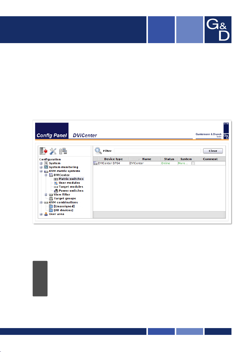
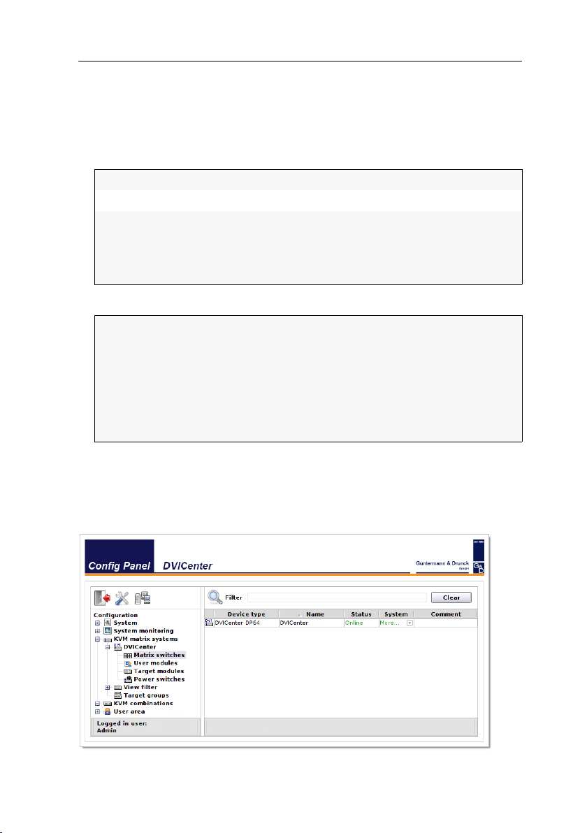
User interface
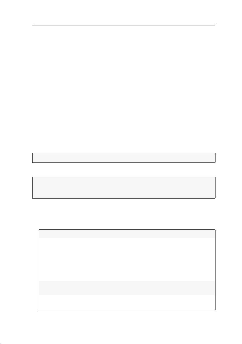
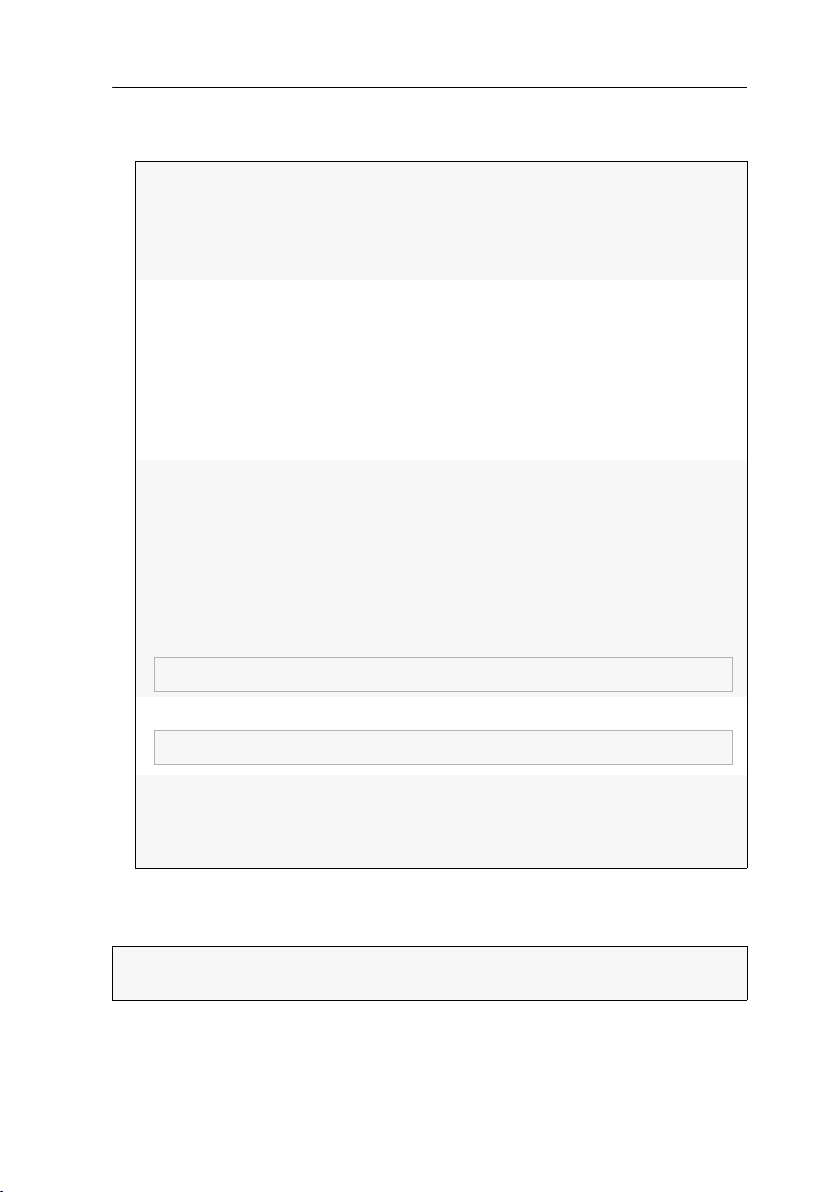
The user interface of the web application consists of four main sections:
Figure 1: User interface
G&D DVICenter · 13

Getting started
The different sectors of the user interface perform various tasks. The following table
lists the intended use of each sector:
Toolbar :
The toolbar allows you to exit the active session and access the
basic configuration of the web application. It is also possible to
use the third icon for viewing and editing the settings of the
Ports.
Tree view :
User name :
Filter function :
The tree view shows the setting options.
Name of user logged in to the web application
The filter function can be used to limit the elements that are
displayed in the main view.
Enter a part of the name of the searched element into the text
field. Now, the main view only displays names that contain
this particular text.
Click Delete to cancel the filtering.
Main view :
After you selected an element in the tree view , the main
view displays the superior elements.
ADVICE:
In the main view of KVM matrix system and KVM combinations,
you can switch between the Monitoring and the Info mode.
The main view of the Monitoring mode shows the values of the monitored features.
The Info mode shows important information like the firmware version, or the
device’s IP and MAC address(es).
Right-click the table, and select Column view > Monitoring or Information to activate the
desired mode.
14 · G&D DVICenter
Getting started
Frequently used buttons
The user interface uses different buttons to carry out certain functions. The following table provides information on the names and functions of the buttons that are
used in many interfaces.
Reload:
Reload window values from the system’s database. Changes that
have been carried out by the user are overwritten.
OK:
Save your settings.
Afterwards, the window closes.
Apply:
Save your settings.
The window remains open.
Cancel:
Print:
Cancel your settings and close window.
Call print interface to select printer, page orientation and further
settings.
After the settings have been selected, the interface information
(e.g., the cascade information) can be printed.
Close:
Close windows.
User logout
Use the Logout button to exit the current session within the web application.
IMPORTANT:
web application against unauthorised access.
How to exit an active session in the web application:
1. Click the Logout button (see figure on the right) to exit the active session in
the web application.
After your logout, the login box is displayed.
Always use the Logout function to exit your session to protect the
G&D DVICenter · 15
Getting started
Selecting the default language of the web application
How to change the default language of the web application:
1. In the directory tree, click on System.
2. Double-click on Configuration in the main view.
3. Click the System tab.
4. Use the Language entry to select the default language to be displayed to all users of
the web application:
German
English
5. Click OK to save your settings.
Selecting the hash algorithm for storing passwords
By default, user passwords are stored as MD5 hash values in the database.
You can also change the hash algorithm to bcyrpt.
NOTE:
The hash algorithm bcrypt is supported from version 1.2.000.
Update the firmware of one of the devices before resetting a backup containing
bcrypt hash values.
How to change the hash algorithm to store passwords:
1. In the directory tree, click on System.
2. Double-click on Configuration in the main view.
3. Click the System tab.
4. Chosse the algorithm from the Hash algorithm options:
MD5
bcrypt
5. Click OK to save your settings.
Showing the version number of the web application
How to show the version number of the web application:
1. In the directory tree, click on System > Information.
2. Double-click on General.
3. Click on Close to close the window.
16 · G&D DVICenter
Getting started
Port administration
NOTE:
The number of Ports depends in the DVICenter variant in use.
The following paragraph explains how to configure the 32 Ports of a
DVICenter DP32 .
The DVICenter DP32 provides 32 Ports. These ports are used to connect user modules
or target modules.
IMPORTANT:
application, the connected user modules (
nized and the ports are auto-configured.
Up to version 1.10 of the web application, the CON or CPU mode of ports could be
manually assigned by the user. After a firmware update to the current version, the
web application of a configured matrix switch activates the Compatibility mode and
applies the user’s previous manual configuration.
ADVICE:
ity mode.
When installing a matrix switch with the current version of the web
CON) or target modules (CPU) are recog-
Click on Compatibility mode to switch between Standard mode and Compatibil-
Automatic port mode
In the default settings, the matrix switch autorecognizes the modules connected to
the ports and configures the ports accordingly.
IMPORTANT:
auto-configured. When cascaded
it, if necessary.
By cascading the matrix switch, you can increase the number of connected target
computers. For this, connect further matrix switches to the configured ports:
When connecting a user module or a target modules, the ports are
(see page 137 ff.) mind the port mode or change
G&D DVICenter · 17
Getting started
UP
D
G
&
UP
D
G
&
UP
D
G
&
UP
D
G
&
UP
D
G
&
UP
D
G
&
UP
D
G
&
UP
D
G
&
DOWN
D
G
&
DOWN
D
G
&
DOWN
D
G
&
DOWN
D
G
&
DOWN
D
G
&
DOWN
D
G
&
DOWN
D
G
&
DOWN
D
G
&
DOWN
D
G
&
DOWN
D
G
&
DOWN
D
G
&
DOWN
D
G
&
DOWN
D
G
&
DOWN
D
G
&
DOWN
D
G
&
DOWN
D
G
&
DOWN
D
G
&
DOWN
D
G
&
DOWN
D
G
&
DOWN
D
G
&
DOWN
D
G
&
DOWN
D
G
&
DOWN
D
G
&
DOWN
D
G
&
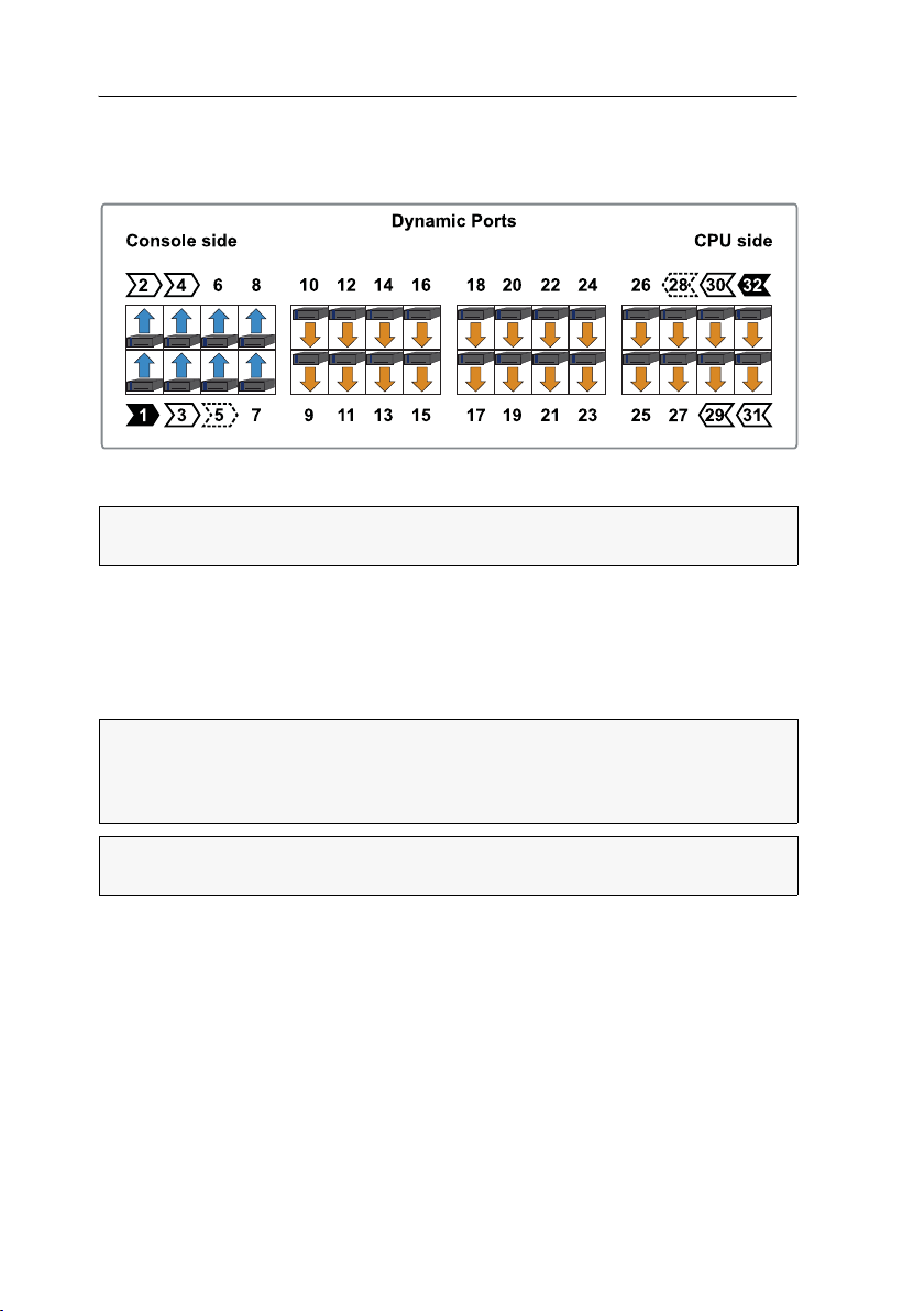
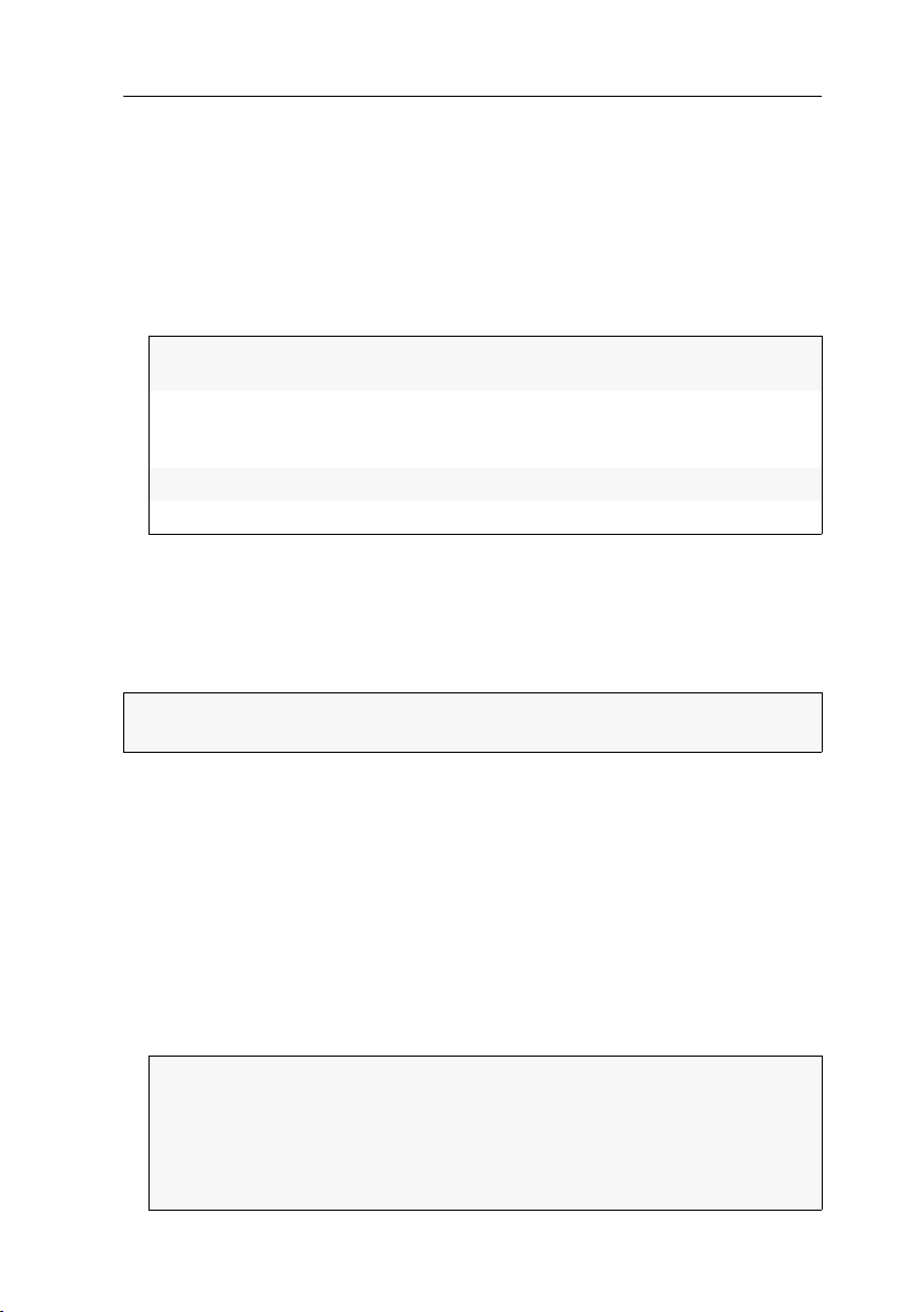
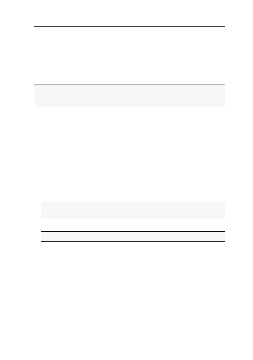
In the default settings, ports 1 through 8 are pre-configured to connect a superior
matrix switch (
Up mode).
Ports 9 through 32 are pre-configured to connect a sub matrix switch (Down mode).
Figure 2: Port settings in default mode
ADVICE:
LEDs to the port mode
To facilitate the installation of the KVM switch, you can switch the port
(see page 20).
To change the port assignment mind the following instructions:
Configure all 32 ports either as Up port or as Down port.
Configure at least one port as Up port and one port as Down port.
Compatibility mode
NOTE:
Up to version 1.10 of the web application, the CON or CPU mode of ports
could be manually assigned by the user. After a firmware update to the current
version, the web application of a configured matrix switch activates the Compatibil
ity mode and applies the user’s previous manual configuration.
ADVICE:
mode.
Click on Compatibility mode to switch between Standard mode and Compatibility
-
18 · G&D DVICenter
Getting started
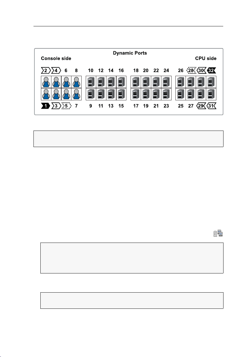
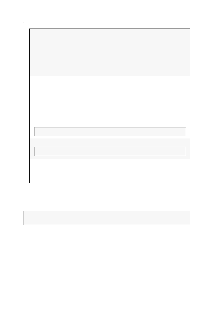
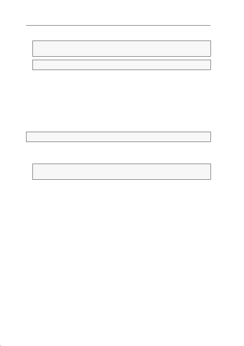
In the default settings, ports 1 through 8 are pre-configured to connect user modules.
Ports
9 through 32 are pre-configured to connect target modules:
Figure 3: Default port assignment
ADVICE:
LEDs to the port mode
To facilitate the installation of the KVM switch, you can switch the port
(see page 20).
To change the assignment of Dynamic Ports, mind the following instructions:
Configure all 32 ports to connect either a user module (CON) or a target module
(CPU).
Configure at least one port to connect either a user module (CON) or a target mod-
ule (CPU).
Configuring ports
You can configure the ports according to your preferences. When doing this, mind
the instructions described in the previous paragraph.
How to configure a port’s mode:
1. Click on the Port configuration icon (see figure on the right) in the toolbar of
the web application.
ADVICE:
In Standard mode, you can switch between Up mode and Down mode of the ports.
In Compatibility mode you can change the ports to connect user modules (
mode
2. Right-click the port whose mode you want to change. Now, you can select the
mode from the context menu.
NOTE:
or Ctrl.
The graphic shows the port configuration.
CON
) and target modules (CPU mode).
You can select multiple ports with the left mouse key while pressing Shift
G&D DVICenter · 19
Getting started
3. Click OK to apply your changes.
IMPORTANT:
After changing the port assignment, the matrix switch restarts.
Showing ports modes
1. In the directory tree, click KVM matrix systems > [Name] > Matrix switches.
2. Right-click the matrix switch whose port mode you want to show. Now, click on
Port LEDs > Show port types
3. Now, the port LEDs show the current port mode:
LED Standard mode Compatibility mode
Yellow
Green
NOTE:
Up mode
Down mode
While showing the port mode, the Identification LEDs on the device’s
front and back are blinking.
4. To restore the standard mode, right-click the matrix switch again. Now, click on
Port LEDs > Show status on the context menu.
on the context menu.
Connection of user modules (CON mode)
Connection of target modules (CPU mode)
20 · G&D DVICenter
Basic configuration of the web application
Basic configuration of the
web
The tool symbol in the toolbar can be used to access the basic configuration of the
web application.
Network settings
The devices with integrated web application are provided with two network interfaces (Network A and Network B). These network interfaces enable you to integrate the
device into up to two separate networks.
application
IMPORTANT:
network settings on page 11.
Please mind the separate instructions regarding Configuring the
Configuring the network settings
Configure the network settings to connect the device to a local network.
How to configure the settings of a network interface:
IMPORTANT:
NOTE:
reserved for the internal communication between devices. An IP address of this
address space cannot be assigned.
1. Click the tools symbol in the toolbar.
2. Click the Network > Interfaces tabs.
3. Use Interface A or Interface B paragraphs to enter the following data:
Operational
mode:
IP address:
It is not possible to operate both network interfaces within one subnet.
According to RFC 3330, the Link Local address space 169.254.0.0/16 is
Use the pull-down menu to select the operating mode of
Interface A or Interface B:
Off: switches off network interface.
Static: uses static settings.
DHCP: obtains the settings from a DHCP server.
Link aggregation active: This interface was added to a group
of network interfaces.
Use the »Link aggregation« tab to configure the network interfaces.
Only if the Static operating mode is selected: Enter the interface IP address.
G&D DVICenter · 21
Basic configuration of the web application
The following settings are automatically obtained in the DHCP operating
mode. Inputs are not possible.
Netmask:
Only if the Static operating mode is selected: Enter the network netmask.
Connection
type:
Select if the network interface and the remote station are to
negotiate the connection type automatically (
Auto) or if one
of the available types is to be applied.
4. Click OK to save the data.
Configuring the global network settings
Even in complex networks the global network settings ensure that the web application is available from all sub networks.
How to configure the global network settings:
1. Click the tools symbol in the toolbar.
2. Click the Network > Interfaces tabs.
3. Enter the following data in the Global network settings section:
Global preferences:
Hostname:
Domain:
Gateway:
DNS Server 1:
DNS Server 2:
Use the pull-down menu to select the operating mode:
Static: uses static settings.
DHCP: obtains the settings from a DHCP server.
Enter the device hostname.
Enter the domain the device is to belong to.
Enter the gateway IP address.
Enter the DNS server IP address.
Optionally, enter the IP address of another DNS server.
4. Click OK to save your data.
22 · G&D DVICenter
Basic configuration of the web application
Increasing the reliability of network connections through link aggregation
In the default settings, you can use both network interfaces at the same time to
access the web application from two different network segments, for example.
To increase the reliability, the network interfaces can be grouped through link aggre-
gation. Only one interface is active within the group. Another interface only becomes
active if the active interface fails.
We provide two different modes to monitor the interfaces:
MII mode: The carrier status of the network interface is monitored through the
Media Independent Interface. This mode only checks the function of the network inter
face.
ARP mode: The address resolution protocol sends requests to an ARP target within the
network. The answer of the ARP target confirms both the functionality of the net
work interface and the proper network connection to the ARP target.
If the ARP target is connected to the network but is temporarily offline, requests
cannot be answered. Define multiple ARP targets to receive an answer from at least
one target if an ARP target fails.
NOTE:
MII and ARP mode cannot be combined.
How to configure the settings of grouped network interfaces:
NOTE:
According to RFC 3330, the Link Local address space 169.254.0.0/16 is
reserved for the internal communication between devices. An IP address of this
addres space cannot be assigned.
-
-
1. Click the tools symbol in the toolbar.
2. Click the Network > Link aggregation tab.
3. Enter the following data into the Network paragraph:
Name:
Operational
mode:
Enter a name for the group of network interfaces.
Choose the operational mode for the grouped network interfaces:
Off: disables link aggregation.
Use the »Interfaces« tab to configure the network interfaces.
Static: A static IP address is assigned.
DHCP: obtain IP address from a DHCP server.
IP address:
Enter the IP address of the interface (only if you have
selected the Static operational mode).
Netmask:
Enter the netmask of the network (only if you have selected
the Static operational mode).
G&D DVICenter · 23

Basic configuration of the web application
4. Enter the following data in the Parameter paragraph:
Primary slave:
Link monitoring:
MII down delay:
MII up delay:
ARP interval:
ARP validate:
ARP target:
Choose if the data traffic should run via Network A (Interface A)
or Network
B (Interface B). As soon as the selected interface is
available, the data traffic is sent via this interface.
If you choose the option None, the data traffic is sent via any
interface. The interface only changes if the active interface is
down.
Choose if you want the MII or ARP mode (description see
below) to be used to monitor the interface.
Time delay in milliseconds before a failed network interface
is disabled.
The value must be a multiple of 100 ms (the MII link monitoring frequency).
Time delay in milliseconds before a reset network interface is
enabled.
The value must be a multiple of 100 ms (the MII link monitoring frequency).
Enter the interval (100 to 10,000 milliseconds) according to
which the incoming ARP packets of the network interfaces
are to be checked.
The validation ensures that the ARP packet for a particular
network interface is generated by one of the listed ARP targets.
Choose if or what incoming ARP packets are to be validated:
None: ARP packets are not validated (default).
Active: Only the ARP packets of the active network inter-
face are validated.
Backup: Only the ARP packets of the inactive network
interface are validated.
All: The ARP packets of all network interfaces within the
group are validated.
The table lists all configured ARP targets.
Use the
New, Edit, and Delete buttons to administrate the ARP
targets.
5. Click OK to save your settings.
24 · G&D DVICenter
Basic configuration of the web application
Reading out the status of the network interfaces
The current status of both network interfaces can be read out via web application.
How to detect the status of the network interfaces:
1. Click the tools symbol in the toolbar.
2. Click the Network > Link status tab.
3. The Interface A and Interface B paragraph provides you with the following data:
Link detected:
Auto-negotiation:
connection to network established (yes) or interrupted
(
no).
The transmission speed and the duplex mode have been
configured automatically (
yes) or manually by the admini-
strator (no).
Speed:
Duplex:
transmission speed
duplex mode (full or half)
4. Click OK to close the window.
Creating and administrating netfilter rules
In the default settings of the devices, all network computers have access to the
Config
Panel web application (open system access).
NOTE:
The open system access enables unrestricted connections via the following
ports: 80/TCP (HTTP), 443/TCP (HTTPS) and 161/UDP (SNMP).
If you create a netfilter rule, the open system access is deactivated and all incoming
data packets are compared to the netfilter rules. The list of the netfilter rules is pro
cessed according to the stored order. As soon as a rule applies, it is carried out and
the following rules are ignored.
Creating new netfilter rules
How to create new netfilter rules:
1. Click the tools symbol in the toolbar.
2. Click the Network > Netfilter tabs.
3. Enter the data described below.
-
Interface:
Use the pull-down menu to select on which network interfaces the data packets are to be trapped and manipulated:
All
Interface A
Interface B
[Name of a group of network interfaces]
G&D DVICenter · 25
Basic configuration of the web application
NOTE:
The IP address and/or a MAC address can be specified within a rule.
NOTE:
The IP address and/or a MAC address can be specified within a rule.
Option:
Use the pull-down menu to select how the rule’s sender
information are to be interpreted:
Normal: The rule applies for data packets whose sender
information does comply with the indicated IP address or
MAC address.
Inverted: The rule applies for data packets whose sender
information does not comply with the indicated IP address
or MAC address.
IP address/
Netmask:
MAC address:
Filter rule: Drop: Data packets whose sender information comply with
Enter the data packet IP address or use the Netmask entry to
enter the address space of the IP addresses.
Examples:
192.168.150.187: for IP address 192.168.150.187
192.168.150.0/24: IP addresses of section 192.168.150.x
192.168.0.0/16: IP addresses of section 192.168.x.x
192.0.0.0/8: IP addresses of section 192.x.x.x
0.0.0.0/0: all IP addresses
Enter the MAC address to be considered in this filter rule.
the IP address or MAC address are not processed.
Accept: Data packets whose sender information comply
with the IP address or MAC address are processed.
4. Click Add to save the data in a new filter rule.
The new filter rule is added to the end of the list of the existing filter rules.
5. Click OK to close the window.
NOTE:
The new netfilter rule does not apply for active connections. Restart the
device to disconnect any active connections. Afterwards, all rules apply.
Editing existing netfilter rules
How to edit an existing netfilter rule:
1. Click the tools symbol in the toolbar.
2. Click the Network > Netfilter tabs.
3. Mark the rule to be changed in the list of the existing netfilter rules.
26 · G&D DVICenter
Basic configuration of the web application
The IP address and/or a MAC address can be indicated within a rule.
NOTE:
The IP address and/or a MAC address can be specified within a rule.
4. The current rule settings are displayed in the upper part of the window. Check
and change the data described on the following page.
Interface:
Option:
IP address/
Netmask:
MAC address:
Use the pull-down menu to select on which network interfaces the data packets are to be trapped and manipulated:
All
Interface A
Interface B
Use the pull-down menu to select how the rule’s sender
information are to be interpreted:
Normal: The rule applies for data packets whose sender
information does comply with the indicated IP address or
MAC address.
Inverted: The rule applies for data packets whose sender
information does not comply with the indicated IP address
or MAC address.
Enter the data packet IP address or – using the Netmask entry
– the address space of the IP addresses.
Examples:
192.168.150.187: for the IP address 192.168.150.187
192.168.150.0/24: IP addresses of section 192.168.150.x
192.168.0.0/16: IP addresses of section 192.168.x.x
192.0.0.0/8: IP addresses of section 192.x.x.x
0.0.0.0/0: all IP addresses
Enter the MAC address to be considered in this filter rule.
Filter rule: Drop: Data packets whose sender information comply with
the IP address or MAC address are not processed.
Accept: Data packets whose sender information comply
with the IP address or MAC address are processed.
5. Click Change to save the changed data.
6. Click OK to close the window.
NOTE:
The changed network rule does not apply for active connections. Restart
the device to disconnect any active connections. Afterwards, all rules apply.
G&D DVICenter · 27
Basic configuration of the web application
Deleting existing netfilter rules
How to delete existing netfilter rules:
1. Click the tools symbol in the toolbar.
2. Click the Network > Netfilter tabs.
3. Mark the rule to be deleted in the list of the existing netfilter rules.
4. Click Remove.
5. Confirm the confirmation prompt by pressing Yes or cancel the process by
clicking
No.
6. Click OK to close the window.
Changing the order/priority of existing netfilter rules
The netfilter rules are processed in the order they are stored. If a rule does apply, the
respective action is carried out and all following rules are ignored.
IMPORTANT:
Please mind the order or priority of the single rules, especially when
adding new rules.
How to change the order/priority of existing netfilter rules:
1. Click the tools symbol in the toolbar.
2. Click the Network > Netfilter tabs.
3. Mark the rule whose order/priority is to be changed in the list of the existing
netfilter rules.
4. Click the button (arrow up) to increase the priority or the button (arrow down)
to decrease the priority.
5. Click OK to close the window.
28 · G&D DVICenter
Basic configuration of the web application
Creating an SSL certificate
Use the free implementation of the SSL/TLS protocol OpenSSL to create an SSL
certificate.
The following websites provide detailed information about operating OpenSSL:
OpenSSL project: http://www.openssl.org/
Win32 OpenSSL: http://www.slproweb.com/products/Win32OpenSSL.html
IMPORTANT:
essary, follow the instructions on the websites mentioned above to install the software.
The following pages give information on creating an X509 certificate.
Creating an X509 certificate requires the software OpenSSL. If nec-
Special features for complex KVM systems
If you want different devices to communicate within a KVM system, use the identical Certificate Authority (see page 29) to create certificates for those devices.
The identical PEM file (see page 32) can also be used for all devices. In this case, all
certificate features are identical.
Creating a Certificate Authority
A Certificate Authority enables the owner to create digital certificates (e. g. for the
matrix switch DVICenter).
How to create a key for the Certificate Authority:
IMPORTANT:
If necessary, read the OpenSSL manual to learn how to create a coded key.
1. Enter the following command into the command prompt and press Enter:
openssl genrsa -out ca.key 4096
2. OpenSSL creates the key and stores it in a file named ca.key.
The following steps describe how to create keys that are not coded.
G&D DVICenter · 29

Basic configuration of the web application
How to create the Certificate Authority:
1. Enter the following command into the command prompt and press Enter:
openssl req -new -x509 -days 3650 -key ca.key -out ca.crt
2. Now, OpenSSL queries the data to be integrated into the certificate.
The following table shows the different fields and an exemplary entry:
Field Example
Country Name (2 letter code) DE
State or Province Name NRW
Locality Name (e.g., city) Wilnsdorf
Organization Name (e.g., company) Guntermann & Drunck GmbH
Organizational Unit Name
(e.g., section)
Common Name (e.g., YOUR name) Guntermann & Drunck GmbH
Email Address
IMPORTANT:
The device's IP address must not be entered under Common Name.
Enter the data you want to state and confirm each entry by pressing Enter.
3. OpenSSL creates the key and stores it in a file named ca.crt.
IMPORTANT:
Distribute the certificate ca.crt to the web browsers using the web
application. The certificate checks the validity and the trust of the certificate
stored in the device.
Creating any certificate
How to create a key for the certificate to be created:
IMPORTANT:
If necessary, read the OpenSSL manual to learn how to create a coded key.
1. Enter the following command into the command prompt and press Enter:
openssl genrsa -out server.key 4096
2. OpenSSL creates the key and stores it in a file named server.key
30 · G&D DVICenter
The following steps describe how to create keys that are not coded.

Basic configuration of the web application
How to create the certificate request:
1. Enter the following command into the command prompt and press Enter:
openssl req -new -key server.key -out server.csr
2. Now, OpenSSL queries the data to be integrated into the certificate.
The following table shows the different fields and an exemplary entry:
Field Example
Country Name (2 letter code) DE
State or Province Name NRW
Locality Name (e.g., city) Wilnsdorf
Organization Name (e.g., company) Guntermann & Drunck GmbH
Organizational Unit Name
(e.g., section)
Common Name (e.g., YOUR name) 192.168.0.10
Email Address
IMPORTANT:
Enter the IP address of the device on which the certificate is to be
installed into the row Common Name.
Enter the data you want to state, and confirm each entry by pressing Enter.
3. If desired, the Challenge Password can be defined. This password is needed if you
have lost the secret key and the certificate needs to be recalled.
4. Now, the certificate is created and stored in a file named server.csr.
Creating and signing the X509 certificate
1. Enter the following command into the command prompt and press Enter:
openssl x509 -req -days 3650 -in server.csr -CA ca.crt -CAkey ca.key -set_serial 01 -out
server.crt
2. OpenSSL creates the certificate and stores it in a file named server.crt.
G&D DVICenter · 31

Basic configuration of the web application
Creating a PEM file
NOTE:
The .pem file contains the following three components:
server certificate
private server key
certificate of the certification authority
If these three components are available separately, enter them successively to the
Clear text entry before updating the certificate stored in the device.
1. Enter the following command(s) into the prompt and press Enter:
a. Linux
cat server.crt > gdcd.pem
cat server.key >> gdcd.pem
cat ca.crt >> gdcd.pem
b. Windows
copy server.crt + server.key + ca.crt gdcd.pem
2. The gdcd.pem file is created during the copying. It contains the created certificate
and its key as well as the Certificate Authority.
Selecting an SSL certificate
By default, each G&D device with integrated web application stores at least one
SSL certificate. The certificate has two functions:
The connection between web browser and web application can be established via
an SSL-secured connection. In this case, the SSL certificate allows the user to
authenticate the opposite side.
If the device’s IP address does not match the IP address stored in the certificate,
the web browser sends a warning message.
ADVICE:
You can import a user certificate so that the device’s IP address
matches the IP address stored in the certificate.
The communication between G&D devices within a system is secured via the
devices’ certificates.
IMPORTANT:
Communication between devices is possible only if all devices
within a KVM system use certificates of the same Certificate Authority
page 29).
32 · G&D DVICenter
(see

Basic configuration of the web application
ADVICE:
Older devices do not support certificate #1. In this case use
certificate #2 or a user certificate.within the KVM system.
How to select the SSL certificate you want to use:
IMPORTANT:
Selecting and activating another certificate terminates all active ses-
sions of the web application.
1. Click the tools symbol in the toolbar.
2. Click the Certificate tab.
3. Select the certificate you want to use:
G&D certificate #1:
G&D certificate #2:
This certificate is enabled for new devices.
This certificate is supported by all G&D devices with integrated web application.
User certificate:
Select this option if you want to use a certificate purchased
from a certificate authority or if you want to use a user cer
tificate.
Now you can import and upload the certificate:
1. Click Import certificate from file and use the file dialog to
select the .pem file you want to import.
You can also copy the plain text of the server certificate,
the server’s private key and the certificate of the certifi
cate authority to the text box.
2. Click Upload and activate to store and activate the impor-
ted certificate for the device.
-
-
3. Click OK to close the window.
Firmware update
The firmware of each device can be easily updated via the web application.
IMPORTANT:
web application has been started!
How to update the firmware:
1. Open the web application of the device whose firmware you want to update.
2. Click the tools symbol in the toolbar.
3. Click the Tools > Firmware update tabs.
This function only updates the firmware of the device on which the
G&D DVICenter · 33
Basic configuration of the web application
4. Enter the storage location and the name of the backup file into the Path entry.
IMPORTANT:
check if you selected the correct device file.
ADVICE:
5. Click on Update now.
6. Click OK to leave the interface.
Use the information provided in the Device and Comment entries to
Use the file dialog to select the location and the name of the update file.
Restoring the default settings
This function enables the user to restore the default settings of the device on which
the web application is operated.
How to restore the default settings:
IMPORTANT:
1. Click the tools symbol in the toolbar.
2. Click the Tools > System defaults tabs.
IMPORTANT:
check if you have selected the correct backup file.
3. Enable the option Reset ports to reset the port configuration.
4. Disable the
work interfaces.
5. Click on System Defaults to reset the current configuration.
All settings are reset.
Use the information provided in the Date and Comment entries to
Reset network config option to maintain the configuration of the net-
34 · G&D DVICenter

Network functions of the devices
Network functions of the devices
The different devices within the KVM system (e.g. KVM extenders and KVM matrix
switches) provide separate network functions.
The following function can be configured for each device within the KVM system:
Authentication against directory services (LDAP, Active Directory, RADIUS,
TACACS+)
Time synchronisation via NTP server
Forwarding of log messages to syslog servers
Monitoring and control of computers and network devices via Simple Network Man-
agement Protocol (see page 54 ff.)
NTP server
The device’s time and date settings can either adjust be adjusted manually or automatically by synchronizing the settings with an NTP server (Network Time Protocol).
Time sync with an NTP server
How to change the NTP time sync settings:
1. Use the tree view to click on KVM matrix systems > [name] > Matrix switches.
2. Right-click the device to be configured. Now click the Configuration entry in the
context menu.
3. Click the Network tab.
4. Click the NTP server tab and enter the following data:
NTP time sync:
NTP server 1:
NTP server 2:
Time zone:
5. Click OK to close the window.
Select the respective entry from the pull-down menu to
(de)activate the time sync:
Disabled
Enabled
Enter the IP address of a time server.
Optionally enter the IP address of a second time server.
Use the pull-down menu to select the time zone of your
location.
G&D DVICenter · 35

Network functions of the devices
Setting time and date manually
How to manually set the time and date of the KVM matrix system:
1. Use the tree view to click on KVM matrix systems > [name] > Matrix switches.
2. Right-click the device to be configured. Now click the Configuration entry in the
context menu.
3. Click the Network > NTP server tabs.
4. If necessary, disable the NTP time sync option. Otherwise, you might not be able to
set time and date manually.
5. Use the Time entry to enter the current time (hh:mm:ss).
6. Use the Date entry to enter the current time (DD.MM.YYYY).
ADVICE:
Click on Accept local date to accept the current system date of the com-
puter on which the Config Panel web application has been started.
7. Click OK.
36 · G&D DVICenter

Network functions of the devices
If you selected the severity code 2 - Critical, messages for this code as well
as for the severity codes 1 - Alert and 0 - Emergency are logged.
Logging syslog messages
The syslog protocol is used to transmit log messages in networks. The log messages
are transmitted to a syslog server that logs the log messages of many devices in the
computer network.
Among other things, eight different severity codes have been defined to classify the
log messages:
0: Emergency
1: Alert
2: Critical
3: Error
4: Warning
5: Note
6: Info
7: Debug
The web application enables you to configure whether the syslog messages are to be
locally logged or sent to up to two syslog servers.
Locally logging the syslog messages
How to locally log the syslog messages:
1. Use the tree view to click on KVM matrix systems > [name] > Matrix switches.
2. Right-click the device to be configured. Now click the Configuration entry in the
context menu.
3. Click the Network tab.
4. Click the Syslog tab and enter the following data in the Syslog local section:
Syslog server:
Log Level:
Select the respective entry from the pull-down menu to define
whether syslog messages are to be sent to a server:
Disabled
Enabled
Use the pull-down menu to select from which severity code
on a log message is to be logged.
The selected severity code and all lower severity codes are
logged.
5. Click OK to close the window.
G&D DVICenter · 37

Network functions of the devices
If you select severity code 2 - Critical, messages for this code and for the
severity codes 1 - Alert and 0 - Emergency are logged.
Sending syslog messages to a server
How to send syslog messages to a server:
1. Use the tree view to click on KVM matrix systems > [name] > Matrix switches.
2. Right-click the device to be configured. Now click the Configuration entry in the
context menu.
3. Click the Network tab.
4. Click the Syslog tab and enter the following data in the Syslog server 1 or
Syslog server 2 section:
Syslog server:
Select the respective entry from the pull-down menu to
define whether syslog messages are to be sent to a server
or not:
Disabled
Enabled
Log Level:
Use the pull-down menu to select from which severity
code on a log message is to be logged.
The selected severity code and all lower severity codes
are logged.
IP address/
DNS name:
Port:
Enter the IP address or the server name to which the syslog messages are to be sent.
Enter the port – usually 514 – on which the server receives
the incoming messages.
Protocol:
Select the protocol – usually UDP – on which the server
receives the incoming messages:
TCP
UDP
5. Click OK to close the window.
38 · G&D DVICenter

Network functions of the devices
Viewing and saving local syslog messages
If the function to log the local syslog messages is activated, these syslog messages
can be viewed and, if necessary, stored in the information window.
How to view and store the local syslog messages:
1. Click on System > Information in the tree view.
2. Right-click the device to be configured. Now click the Configuration entry in the
context menu.
3. Double-click on Syslog in the main view.
4. Click the Fetch syslogs tab.
The matrix switch calls the local syslog messages, which are now displayed in the
text field.
ADVICE:
If necessary, click Save to save these messages in a text file. The open-
ing file window enables you to select the location and a file name.
Afterwards, click Save.
5. Click OK to close the window.
G&D DVICenter · 39

Network functions of the devices
User authentication with directory services
In in-house networks, the user accounts of different users are often administrated by
a directory service. The device can access such a directory service and authenticate
users against the directory service.
NOTE:
If the Admin user account cannot be authenticated by the directory service,
the user account is authenticated by the device’s data base.
The directory service is exclusively used to authenticate a user. The user rights are
assigned within a database of the KVM system. The following paragraphs describe the
different scenarios:
The user account exists within the directory service and the KVM system
The user can log in with the password stored in the directory service. After the
login, the user is assigned with the rights of the correspondent account in the
KVM system.
NOTE:
The password which the user used to log in, is taken over into the data-
base of the KVM system.
The user account exists within the directory service, but not within the KVM system
A user that has been successfully authenticated against the directory service, but
does not have an account of the same name within the database of the KVM sys
tem, is assigned with the rights of the RemoteAuth user.
If required, change the rights of this particular user account to set the rights for
users without a user account.
-
ADVICE:
Deactivate the RemoteAuth user to prevent users without user accounts
to log in to the KVM system.
The user account exists within the KVM system, but not within the directory service
If the directory service is available, it reports that the user account does not exist.
The access to the KVM system is denied to the user.
If the server is not available, but the fallback system is active (see below), the user
can log in with the password that is stored within the KVM system.
IMPORTANT:
Mind the following safety instructions to prevent a locked or deactivated user from logging in to the system in case the connection to the directory
service fails:
If a user account is deactivated or deleted in the directory service, this action
can also be carried out within the user database of the KVM system.
Only activate the fallback system in reasonable exceptional cases.
40 · G&D DVICenter

Network functions of the devices
ADVICE:
After the directory service has been selected, collect the settings of
the directory service server in the
Server settings.
IMPORTANT:
Mind the following safety instructions to prevent a locked or
deactivated user from logging in to the system in case the connection to
the directory service fails:
If a user account is disabled or deleted in the directory service, this action
can also be carried out within the user database of the KVM system.
Only activate the fallback system in reasonable exceptional cases.
How to configure the user account authentication:
NOTE:
If no directory service is applied, the user accounts are administered by the
device.
1. Use the tree view to click on KVM matrix systems > [name] > Matrix switches.
2. Right-click the device to be configured. Now, click the Configuration entry in the
context menu.
3. Click the Network > Authentication tabs and enter the following data:
Auth. Server:
Select the Local option if the user administration is to be carried out by the KVM system.
If a particular directory service is to be applied, select the
respective entry from the pull-down menu:
LDAP
Active Directory
Radius
TACACS+
Fallback:
Activate this option if the local user administration of the
KVM system is to be applied in case the directory service is
temporarily not available.
4. Click OK to close the window.
G&D DVICenter · 41

Monitoring functions
Monitoring functions
The current monitoring values of all devices within the KVM system can be viewed in
the device-specific branches (e.g. KVM matrix systems) as well as in the KVM Combina
tions and Critical Devices branches of the tree view.
The various information regarding a device can either be displayed in individual values or in monitoring groups, which are sorted according to topic. The following
exemplary figure shows the Status values and three different monitoring groups:
Figure 4: Detailed view of an exemplary monitoring table
Individual values (the Status value in the figure above) immediately show if the status is
correct (green) or deviating from the normal operating value (red). The text in the col
umn also provides information about the current status.
Monitoring groups allow you to group various individual values. The column of a
monitoring group shows if all values are within range (green) or if at least one value is
deviating from the normal operating values (red).
Clicking the arrow in the column opens a separate window, which displays the individual values of the group.
-
-
42 · G&D DVICenter

Monitoring functions
Viewing monitoring values
NOTE:
An overview of the possible monitoring values of all different device types
is given on
By applying different monitoring sets, the monitoring values are displayed in the different branches of the tree view.
Several branches (e.g. Critical devices) provide another view to enable the user to
detect critical monitoring values as fast as possible.
Listing values by applying monitoring sets
A monitoring set defines which individual values and groups are to be displayed.
The column, which shows the individual values, enables you to read the status and
check whether it is deviating from the normal operating values.
Monitoring groups allow you to group various individual values. The column of a
monitoring group shows if all values are within range (green) or if at least one value is
deviating from the normal operating values (red).
Clicking the arrow in the column opens a window, which contains detailed information regarding the individual values of the group.
page 123 ff.
ADVICE:
ing monitoring groups and monitoring sets.
The following pages of this chapter provide detailed information regard-
Listing individual values of critical devices
If a device shows a value that deviates from the normal operating values, the device
is additionally listed in the Critical devices branch. This branch displays all deviating
(red) values in tabular form. This way, deviating values can be detected as fast as
possible.
NOTE:
To be able to find deviant values as fast as possible, monitoring sets are not
applied here.
Disabling monitoring values
Any monitoring value can be disabled. After disabling, the monitoring values are no
longer shown in the web application.
IMPORTANT:
ues. No SNMP traps are sent regarding these values.
How to enable/disable the monitoring values:
1. Use the tree view to click on KVM matrix systems > [name] > Matrix switches.
2. Right-click the device to be configured. Now, click the Configuration entry in the
context menu.
The web application does not show any warnings about disabled val-
G&D DVICenter · 43

Monitoring functions
3. Click the Monitoring tab.
Two tables list the monitoring values of the KVM system:
Enabled:
Disabled:
To give you a faster overview, the values are grouped in both columns.
4. Mark the monitoring values to be enabled/disabled.
5. Click the button (right arrow key) to disable the monitoring value or
(left arrow key) for enabling.
6. Click OK to save your settings.
lists all active monitoring values.
lists all inactive monitoring values.
Advanced function regarding the administration of critical devices
The Critical Devices branch lists the devices that show at least one value that exceeds
the normal operating values.
NOTE:
A sub-branch is displayed for each device class in the KVM system (e. g.
KVM matrix systems).
Messages regarding critical statuses of devices
If one value exceeds the normal operating values, the branch is marked red. A blinking message under the main view points to this condition.
ADVICE:
the Critical devices branch.
Click on the blinking message to show the list of the deviating values in a separate
window.
If the blinking message appears on your screen, press Ctrl+Space to open
Viewing the list of critical devices
How to view the list of critical devices:
1. Click on the System monitoring > Critical Devices folders in the tree view.
The main view lists all affected devices. The critical values are displayed in the table.
ADVICE:
particular device class.
44 · G&D DVICenter
Click a sub-branch of the folder in order to only list the devices of a

Monitoring functions
Marking messages from critical devices as read
Many messages require immediate actions from the administrator. Other messages
(e.g. the break-down of the redundant power supply), however, point to possibly
uncritical conditions.
In such a case, all peculiar values of a device can be marked as read, which causes
the following:
A device whose deviating values have been marked as read shows no blinking status
bar.
The cells, info dialogues and monitoring windows of all “read” devices are high-
lighted in yellow.
If a monitoring group contains critical values, which have been marked as read,
the column displays Error. In addition, the cell is highlighted in yellow.
NOTE:
The system only highlights values that have been deviating from the normal
operating values at the time the function has been executed. The web application
shows if another monitoring value of such a device deviates from the normal operat
ing values.
How to mark the Monitoring messages of a device as read:
1. Click on the System monitoring > Critical Devices folders in the tree view.
2. Right-click the desired device. Now click the Acknowledge entry of the context menu.
-
Administrating monitor groups
IMPORTANT:
branch in which they were created.
If a monitoring group was created in a device-specific branch, it is no longer available in the KVM combinations branch.
The Config Panel web application already provides several default monitoring
groups. Those groups can neither be edited nor deleted, but they can be duplicated
and individually adjusted to your wishes.
All groups that were preconfigured or created are shown in the monitoring table as
long as they are contained in the applied monitoring set
Figure 5: Status of different devices in the »Group #1« monitoring group
Any recently created monitoring groups are only available in the
(see page 49 ff.):
G&D DVICenter · 45

Monitoring functions
ADVICE:
Due to the high amount of individual values, it is recommended to display
the most important values as individual values and group the rest in groups accord
ing to topic.
This provides a quick overview and the values are displayed in a space-saving way.
Adding monitoring groups
How to add a new monitoring group:
1. Right-click the KVM combinations branch in the tree view.
2. Click the Monitoring groups entry in the context menu.
3. Click New.
4. Enter the name and an optional comment for the new group.
5. Click OK to create the group.
Changing name and/or comment of monitoring groups
How to change the name and/or comment of a monitoring group:
1. Right-click the KVM combinations branch in the tree view.
2. Click the Monitoring groups entry in the context menu.
3. Select the group to be edited and click Edit.
4. Change the name and/or the optional comment of the group.
5. Click OK to save your settings.
-
Assigning members to monitoring groups
How to assign members to a monitoring group:
1. Right-click the KVM combinations branch in the tree view.
2. Click the Monitoring groups entry in the context menu.
3. Select the group to be edited and click Edit.
4. Click the Member tab.
Now you have the possibility to add members to or delete them from a monitoring
group.
The window consists of two tables, which list the monitoring values of the KVM
system:
Unassigned:
Assigned:
5. Mark the monitoring value you want to add to or delete from the group.
46 · G&D DVICenter
lists monitoring values that are not assigned to this group
lists monitoring values that are assigned to this group

Monitoring functions
6. Click (right arrow) to add the monitoring value to the group or (left arrow) to
delete it from the member list.
7. Click OK to save your settings.
Duplicating monitoring groups
The KVM combinations branch as well as many other device-specific branches contain
several default groups. These groups are displayed in light grey.
IMPORTANT:
It is not possible to edit or delete a default monitoring group.
If you want to create a new group based on an already existing group, simply duplicate the existing group and edit the duplicate.
How to duplicate a monitoring group:
1. Right-click the KVM combinations branch in the tree view.
2. Click the Monitoring groups entry in the context menu.
3. Select the group to be duplicated and click Edit.
4. Enter the name and an optional comment for the group.
5. Click Duplicate to duplicate the existing group.
6. Edit the new group as described on the previous page or click Close to close the
window.
Deleting monitoring groups
The KVM combinations branch as well as many other device-specific branches contain
several default groups. These groups are displayed in light grey.
IMPORTANT:
How to delete a monitoring group:
1. Right-click the KVM combinations branch in the tree view.
2. Click the Monitoring groups entry in the context menu.
3. Select the group to be deleted and click Delete.
4. Confirm the confirmation prompt be clicking Yes or cancel the task by clicking No.
5. Click Close to save your settings.
It is not possible to edit or delete a default monitoring group.
G&D DVICenter · 47

Monitoring functions
Administrating monitoring sets
A monitoring set defines the individual values and the groups to be displayed in a
subfolder of the KVM combinations branch or a device-specific branch:
Figure 6: Status of the individual Status value and three groups of a monitoring set
The Config Panel web application already provides several default monitoring
groups. The groups can neither be edited nor deleted, but they can be duplicated and
individually adjusted to your wishes.
It is also possible to create and configure a new group.
IMPORTANT:
which they have been created.
If a monitoring set has been created in a device-specific branch, it is no longer displayed in the KVM combinations branch!
The created monitoring sets are only displayed in the branch in
Adding monitoring sets
How to add a monitoring set:
1. Right-click the KVM combinations branch in the tree view.
2. Click the Monitoring set entry in the context menu.
3. Click New.
4. Enter the name and an optional comment for the new set.
5. Click OK to create the set.
Changing name and/or comment of monitoring sets
How to change the name and/or comment of a monitoring set:
1. Right-click the KVM combinations branch in the tree view.
2. Click the Monitoring sets entry in the context menu.
3. Select the set to be edited and click Edit.
4. Enter the name and an optional comment for the set.
5. Click OK to save your settings.
48 · G&D DVICenter
Assigning members to monitoring sets
Monitoring functions
IMPORTANT:
It is important to define your desired monitoring groups (see
page 45 ff.) before creating a monitoring set.
How to assign members to a monitoring set:
1. Right-click the KVM combinations branch in the tree view.
2. Click the Monitoring sets entry in the context menu.
3. Select the set to be edited and click Edit.
4. Click the Member tab.
Now you have the possibility to add members to or delete them from a monitoring set.
The entry consists of two tables which list the monitoring values of the KVM system. The values are the divided into the sub categories
Individual values and Groups (Columns).
NOTE:
Click on the [-] in the category header to hide the content of this cate-
gory. Clicking on [+] shows the contents.
The different values are either listed in the left or the right-hand table:
Unassigned:
Assigned:
lists monitoring values that are not assigned to this set
lists monitoring values that are assigned to this set
5. Mark the monitoring value you want to add to or delete from the group.
6. Click (right arrow) to add the monitoring value to the set or (left arrow) to
delete it from the member list.
7. Click OK to save your settings.
Selecting a monitoring set in the folder configuration
After a monitoring set has been created, it can be activated in the configuration of
one (or more) folders of the tree view.
How to activate a monitoring set:
1. Right-click a subfolder of the KVM combinations branch in the tree view.
2. Click the Configuration entry in the context menu.
G&D DVICenter · 49

Monitoring functions
3. Use the Monitoring set entry to select the desired set.
IMPORTANT:
The created monitoring sets are only displayed in the branch in
which they have been created.
If a monitoring set has been created in the KVM extenders branch, it is no longer
displayed in the KVM combinations branch!
4. Click OK to activate the selected set.
Duplicating monitoring sets
The KVM combinations branch as well as many other device-specific branches contain
several default groups. Those groups are displayed in light grey.
IMPORTANT:
It is not possible to edit or delete those groups.
If you want to create a new set based on an already existing set, simply duplicate the
existing set and edit the duplicate.
How to duplicate a monitoring set:
1. Right-click the KVM combinations branch in the tree view.
2. Click the Monitoring sets entry in the context menu.
3. Select the set to be duplicated and click Edit.
4. Enter the name and an optional comment for the set.
5. Click Duplicate to duplicate the existing set.
6. Edit the new set as described on the previous page or click Close to close the window.
Deleting monitoring sets
The KVM combinations branch as well as many other device-specific branches contain
several default groups. These groups are displayed in light grey.
IMPORTANT:
These groups cannot be edited or deleted.
How to delete a monitoring set:
1. Right-click the KVM combinations branch in the tree view.
2. Click the Monitoring sets entry in the context menu.
3. Select the set to be deleted and click Delete.
4. Confirm the confirmation prompt be clicking Yes or cancel the task by clicking No.
5. Click Close to save your settings.
50 · G&D DVICenter
Device monitoring via SNMP
Device monitoring via SNMP
The Simple Network Management Protocol (SNMP) is used to monitor and control computers and network devices.
Practical use of the SNMP protocol
A Network Management System (NMS) is used to monitor and control computers and
network devices. The system queries and collects data from the agents of the moni
tored devices.
NOTE:
An Agent is a program, which runs on the monitored device and detects its sta-
tus. Via SNMP, the detected data are transmitted to the Network Management System.
If an Agent detects a severe failure within the device, it can send a Trap packet to the
Network Management System. This way, the administrator is directly informed about
such occurrences.
Configuring the SNMP agent
How to configure the SNMP agent:
1. Use the tree view to click on KVM matrix systems > [name] > Matrix switches.
2. Right-click the device to be configured. Now click the Configuration entry in the
context menu.
3. Click the Network> SNMP Agent tabs.
4. Enter the following data in the Global paragraph:
-
Status:
Protocol:
Port:
SysContact:
SysName:
SysLocation:
Select the particular entry to either switch the SNMP agent
Off) or on (Enabled).
off (
Select the protocol (TCP or UDP) – normally UDP – via which
the SNMP packets are to be transmitted.
Define the port – normally 161 – on which the incoming
SNMP packets are to be accepted.
Enter the admin’s contact data (e.g. direct dial or email
address).
Enter the device name.
Enter the location of the device.
G&D DVICenter · 51
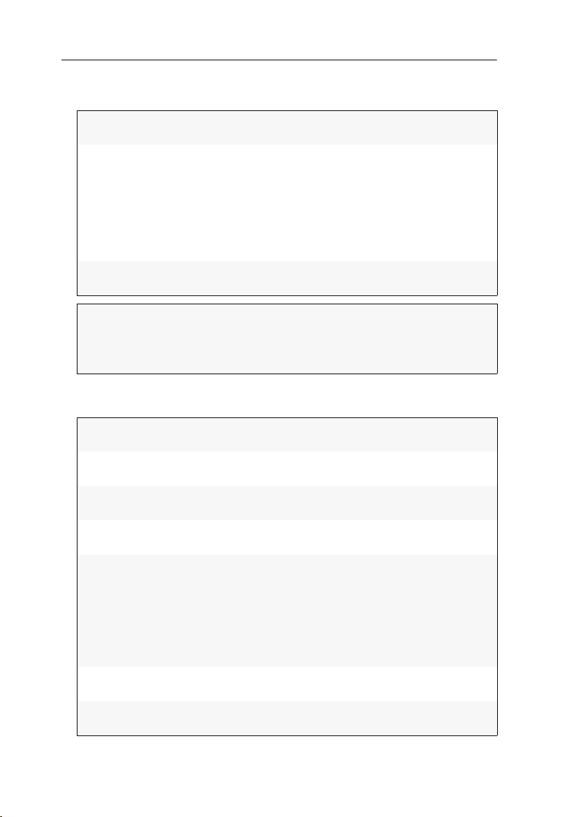
Device monitoring via SNMP
5. If you want to process the packets of the SNMPv2c protocol version, enter the fol-
lowing data in the paragraph of the same name:
Access:
Activate the View access (View) or deny the access (No) via
SNMPv2c protocol.
Source:
Enter the IP address or the address space of the addresses of
incoming SNMP packets.
Examples:
192.168.150.187: Only IP address 192.168.150.187
192.168.150.0/24: IP addresses of space 192.168.150.x
192.168.0.0/16: IP addresses of space 192.168.x.x
192.0.0.0/8: IP addresses of space 192.x.x.x
Read-only
community:
IMPORTANT:
Enter the name of the Community which has also been
selected in the Network Management System.
The transfer of the packet password (Community) of the SNMPv2c
protocol version is not encrypted. Therefore, it can be easily tapped!
If required, use the SNMPv3 protocol version (see below) and a high Securitiy
level to ensure a secure data transfer.
6. If you want to process the packets of the SNMPv3 protocol version, enter the fol-
lowing data in the respective paragraph:
Access:
Activate the View access (View) or deny the access (No) via
SNMPv3 protocol.
User:
Enter the username for the communication with the Network Management System.
Authentication
protocol
Authentication
passphrase
Security level
Select the authentication protocol (MD5 or SHA) which has
been activated in the Network Management System.
Enter the authentication passphrase for the communication
with the Network Management System.
Select between one of the following options:
NoAuthNoPriv: user authentication and Privacy protocol
deactivated
AuthNoPriv: user authentication activated, Privacy proto-
col deactivated
AuthPriv: user authentication and Privacy protocol acti-
vated
Privacy protocol:
Select the Privacy protocol (DES or AES) which has been
activated in the Network Management System.
Privacy
passphrase:
Enter the privacy passphrase for secure communication with
the Network Management System.
52 · G&D DVICenter

Device monitoring via SNMP
NOTE:
Inputs are only possible if the Inform option has been selected in the
Notification type entry.
NOTE:
Inputs are only possible if the Inform option has been selected in the
Notification type entry.
Engine ID method:
Select how the SnmpEngineID should be assigned:
Random: The SnmpEngineID is re-assigned with every
restart of the device.
Fix: The SnmpEngineID is the same as the MAC address of
the device’s network interface.
User: The string entered under Engine ID is used as
SnmpEngineID.
Engine ID:
When using the Engine ID method User, enter a string that is
used as Engine ID.
7. Click OK to save your settings and to leave the window.
Configuring SNMP traps
How to add a new trap or edit an existing trap:
1. Use the tree view to click on KVM matrix systems > [name] > Matrix switches.
2. Right-click the device to be configured. Now click the Configuration entry in the
context menu.
3. Click the Network > SNMP trap tabs.
4. Click Add or Edit.
5. Enter the following data in the Global paragraph:
Server:
Protocol:
Port:
Retries:
Enter the IP address of the Network Management Servers.
Select the protocol (TCP or UDP) – normally UDP – via which
the SNMP packets are to be transmitted.
Define the port – normally 162 – on which the outgoing
SNMP packets are to be accepted.
Enter the number of retries to send an SNMP Inform.
Timeout:
Enter the time (in seconds) after which an SNMP Inform is to
be sent again if you have received no confirmation.
G&D DVICenter · 53

Device monitoring via SNMP
NOTE:
If you select the 2 - Critical, severity level SNMP traps are sent for
occurrences from this level and from the 1 - Alarm and 0 - Emergency severity
levels.
NOTE:
Inform packets require a confirmation of the Network Management Sys-
tem. If this confirmation is not available, the transmission is repeated.
Log level:
Select from which severity level an SNMP trap is to be sent.
The selected severity level and all lower severity levels are
logged.
Version:
Select if the traps are to be created and sent according to the
SNMPv2c (v2c) or SNMPv3 (v3) protocol.
Notification type:
Select if the occurrences are sent as Trap or Inform packet.
6. If you use the SNMPv2c protocol version, use the respective paragraph to enter the
same Community name as selected in the Network Management System.
IMPORTANT:
The transfer of the packet password (Community) of the SNMPv2c
protocol version is not encrypted. Therefore, it can be easily tapped!
If required, use the SNMPv3 protocol version (see below) and a high Security level
to ensure a secure data transfer.
7. If you decided to use the SNMPv3 protocol version, use the respective paragraph to
enter the following data:
User:
Enter the username for communication with the Network
Management System an.
Authentication protocol
Authentication
passphrase
Security level
Select the authentication protocol (MD5 or SHA) which has
been activated in the Network Management System.
Enter the authentication passphrase for the communication
with the Network Management System.
Select between one of the following options:
NoAuthNoPriv: deactivated user authentication and Privacy
protocol
AuthNoPriv: activated user authentication, deactivated Pri-
vacy protocol
AuthPriv: activated user authentication and Privacy protocol
Privacy protocol:
Select the privacy protocol (DES or AES) which has been
activated in the Network Management System.
54 · G&D DVICenter
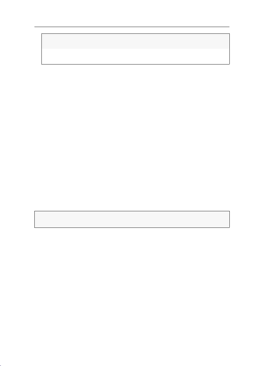
Device monitoring via SNMP
Privacy
passphrase:
Engine ID:
Enter the privacy passphrase for secure communication with
the Network Management System.
Enter an Engine ID which clearly identifies the SNMP agent
within the network.
8. Click OK to save your settings and to leave the window.
How to delete existing traps:
1. Use the tree view to click on KVM matrix systems > [name] > Matrix switches.
2. Right-click the device to be configured. Now click the Configuration entry in the
context menu.
3. Click the Network > SNMP trap tabs.
4. Select the receiver to be deleted and click Delete.
5. Click OK to save your settings and to leave the window.
How to generate a test event:
1. Use the tree view to click on KVM matrix systems > [name] > Matrix switches.
2. Right-click the device to be configured. Now click the Configuration entry in the
context menu.
3. Click the Network > SNMP trap tabs.
4. Click on Generate test event.
5. Click OK to save your settings and to leave the window.
NOTE:
If properly configured, the Trap message is displayed within your Network
Management System.
G&D DVICenter · 55

Logbook
Logbook
The Logbook of a device of the KVM system allows you to collect any information.
ADVICE:
assign the entry with a status (»Open«).
After these changes have been carried out, assign the »Closed« status to the logbook entry. This way you can refer to the logbook to look up the times at which
the changes have been made.
If you want to save the logbooks or edit them with other programs, the logbooks of
the different devices can be printed, copied to the clipboard, or exported to a file.
Write down if you plan on changing the configuration of the device and
The dialogue entries of the logbook
After the logbook has been called up, the »Logbook configuration« dialog shows an
overview of all logbook entries that have been saved so far.
All details regarding the entry are shown by double-clicking.
The »Logbook configuration« window
The Logbook configuration window shows a table with all logbook entries that have
been made until then.
The table displays the Subject and Status (»Open« or »Closed«) and the Date the entry
has been last edited.
NOTE:
By default, the table is sorted in descending order according to the contents
of the »Status« column. This order is indicated by a small triangle in the column
header.
If you want to sort the entries according to the contents of another column, click
the header of the desired column. Another click reverses the sort sequence.
The following actions can be carried out in the logbook:
New: create a new logbook entry
Edit: update an existing logbook entry
Delete: delete a logbook entry
Print: print a logbook entry
Export: export the data of the logbook entry to csv file
Copy: copy the details of the logbook entry to the clipboard
56 · G&D DVICenter

Logbook
Viewing a logbook entry in detail
Double-click a logbook entry to show its details. The overview provides the following information:
Subject:
short description (max. 128 characters) that allows a quick
overview in the table and on the print-out
Body:
Status:
Creator:
Created:
Last editor:
Last edited:
detailed description (max. 1.024 characters)
current status (»Open« or »Closed«)
user name of the person who created the logbook entry
date and time the entry has been originally created
user name of the person who last changed the entry
date and time the entry has been last changed
The upper part of the window shows several buttons that provide the following
functions:
(left arrow): shows the previous logbook entry (if available)
Print: print logbook entry
Export: export the data of the logbook entry to csv file
Copy: copy the details of the logbook entry to the clipboard
(right arrow): shows the last logbook entry (if available)
NOTE:
The functions of the Print, Export and Copy buttons correspond to the entries
of the same name in the context menu of the logbook entries.
These functions are described on the following pages.
Basic logbook functions
The basic logbook functions enable you to create new or edit and delete the existing
logbook entries.
IMPORTANT:
Any device within a KVM system provides a separate logbook.
Creating a new logbook entry
How to create a new logbook entry for a device:
1. Click on the folder that contains the device whose logbook you want to open.
2. Right-click on the desired device and click on Logbook in the context menu.
3. Click on New.
G&D DVICenter · 57

Logbook
4. Enter the Status (max. 128 characters) of the logbook entry.
ADVICE:
The subject is shown in the overview of the logbook entries and
allows a quick overview of the entries.
5. If necessary, use the Body entry to change the detailed description (max. 1.024
characters) of the logbook entry.
6. Click OK to save the logbook entry.
Changing a logbook entry
How to change the logbook entry of a device:
1. Click on the folder that contains the device whose logbook entry you want to
change.
2. Right-click on the desired device and click on Logbook in the context menu.
3. Click the entry to be edited and click on Edit.
4. If necessary, change the Subject (max. 128 characters) of the logbook entry.
ADVICE:
allows a quick overview of the entries.
5. If necessary, use the Body entry to change the detailed description (max. 1.024
characters) of the logbook entry.
6. Use the Status button to select between the »Open« and »Closed« options.
7. The following information are provided in this dialog:
Creator:
Created:
Last editor:
Last edited:
The subject is shown in the overview of the logbook entries and
user name of the person that created the logbook entry
date and time the entry has been originally created
user name of the person that last changed the entry
date and time the entry has been last changed
8. Click OK to save the logbook entry.
58 · G&D DVICenter

Logbook
Deleting a logbook entry
How to delete the logbook entry of a device:
1. Click on the folder that contains the device whose logbook entry you want to
delete.
2. Right-click on the desired device and click on Logbook in the context menu.
3. Click the entry to be deleted and click on Delete.
4. Confirm the confirmation prompt by clicking Yes or cancel the process by click-
ing No.
Advanced functions
The advanced functions allow you to print or export the logbook entries. The data of a
logbook entry can also be copied to the clipboard.
The advanced functions can either be called up via the buttons in the detail dialog of
the logbook or the context menu of the »Logbook configuration« dialog.
NOTE:
The functions of several logbook entries can only be applied if they have
been called up via the context menu.
Printing logbook entries
How to print one or several logbook entries:
1. Click on the folder that contains the device whose logbook entry you want to
change.
2. Right-click on the desired device and click on Logbook in the context menu.
3. Mark one or several existing logbook entries.
NOTE:
To select several logbook entries, press the Ctrl key and select the differ-
ent entries by mouse.
4. Right-click one of the marked entries and click on Print.
5. Select the Printer on which the document is to be printed.
NOTE:
If desired, you can also adjust the headline, the number of copies, the
page layout and the frame settings.
6. Click on Print.
G&D DVICenter · 59

Logbook
Exporting logbook entries
Use the export function to export the data of a logbook entry to a CSV file.
This file format is usually used for exchanging data between different programs. A
CSV file that has been created with the Config
all common spreadsheet programs, for example.
NOTE:
CSV is short for Comma-Separated Values.
How to export one or several logbook entries:
1. Click on the folder that contains the device whose logbook entry you want to
change.
2. Right-click on the desired device and click on Logbook in the context menu.
3. Mark one or several existing logbook entries.
NOTE:
To select several logbook entries, press the Ctrl key and select the differ-
ent entries by mouse.
4. Right-click one of the marked entries and click on Export.
5. Use the File Name section to select the location and the file name of the file to be
created.
6. The configuration section offers the following settings:
Panel web application can be read with
Column
headings:
Delimiter:
7. Click on Export.
60 · G&D DVICenter
Select if the column headings (Subject, Body, …) are to be output
in the CSV file.
Options: Yes, No
Select the desired delimiter between the different data fields in
the CSV file.
Options: Tabulator, Semicolon, Comma, Space

Logbook
Copying the logbook entries
As an alternative to the export function, which creates a CSV file, the copy function
can be used to copy logbook entries to the clipboard of the operating system.
The copied data can be pasted to any application that has access to the clipboard.
How to copy one or several logbook entries:
1. Click on the folder that contains the device whose logbook entry you want to
change.
2. Right-click on the desired device and click on Logbook in the context menu.
3. Mark one or several existing logbook entries.
NOTE:
To select several logbook entries, press the Ctrl key and select the differ-
ent entries by mouse.
4. Right-click one of the marked entries and click on Copy.
5. Open a document in the application to which you want to copy the data and
press
Ctrl+V.
G&D DVICenter · 61

Shared editing
Shared editing
The web application enables two users with the respective rights to edit settings at
the same time.
For example, if two users simultaneously change the user account settings, the web
application informs the other user about these changes:
A message in purple appears in the upper row of the footer and highlights the
other user’s changes.
The changed setting or the menu item in the submenu, which contains this set-
ting, is displayed in green.
The following options are provided to process the collected data:
Discard data:
Overwrite all data:
Only save own changes:
1. Click on Reload to read the current values of the
dialogue from the database.
1. Click on Accept.
2. Click on Overwrite all data.
1. Click on Accept.
2. Click on Only save own changes.
62 · G&D DVICenter
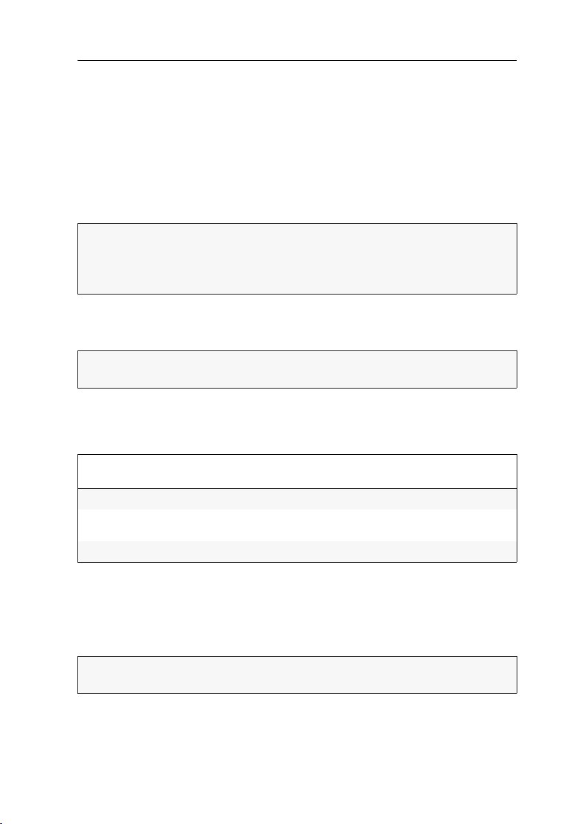
Users and Groups
Users and Groups
Efficient rights administration
The web application administrates up to 256 user accounts as well as the same
amount of user groups. Any user within the system can be a member of up to 20
groups.
The user accounts and the user groups can be provided with different rights to operate the system.
ADVICE:
user groups. Therefore, the user groups and the assigned rights have to be planned
and implemented beforehand.
This way, the user rights can be quickly and efficiently changed.
The rights administration can almost be carried out completely through
The effective right
The effective right determines the right for a particular operation.
IMPORTANT:
account’s individual right and the rights of the assigned group(s).
EXAMPLE:
The following table shows the user account rights, the rights of the assigned groups,
and the resulting effective right:
Right User
Target config
Change own
password
Target access
The settings of the Target config and Change own password rights result from the rights
assigned to the user groups. The Target access right which, in this case, enables full
access, was given directly in the user account.
The dialogue windows of the web application additionally display the effective right
for every setting.
The effective right is the maximum right, which consists of the user
The user JDoe is member of the Office and TargetConfig groups.
Group
JDoe
No No Yes Yes
No Yes No Yes
Full View No Full
Office
Group
TargetConfig
Effective
right
ADVICE:
assigned to the user account.
Click the Details button to get a list of the groups and rights that are
G&D DVICenter · 63

Users and Groups
Efficient user group administration
User groups enable the creation of a shared right profile for several users with identical rights. Furthermore, the user accounts that are included in the member list can
be grouped and therefore no longer have to be individually configured. This facili
tates the rights administration within the matrix system.
If the rights administration takes place within the user groups, the user profile only
stores general data and user-related settings (key combinations, language settings, …).
When initiating the matrix system, it is recommended to create different groups for
users with different rights (e.
accounts to these groups.
EXAMPLE:
ple, some users of the »Office« group are to be provided with the multi-access right, a
respective user group can be created:
Create a user group (e. g., »Office_MultiAccess«) with identical settings for the »Office«
group. The multi-access right is set to full. Assign the respective user accounts to this
group.
Create a user group (e. g., »MultiAccess«) and only set the multi-access right to Yes. In
addition to the »Office« group, also assign the respective user accounts to this
group.
In both cases, the user is provided with the full effective right for multi-access.
Creat more groups if the user rights are to be further divided. If, for exam-
g., »Office« and »IT«) and assign the respective user
-
ADVICE:
group member.
The user profile offers the possibility to provide extended rights to a
Administrating user accounts
User accounts enable you to define individual rights for every user. The personal
profile also provides the possibility to define several user-related settings.
IMPORTANT:
mitted to create and delete user accounts and edit rights and user-related settings.
64 · G&D DVICenter
The administrator and any user that holds the Superuser right are per-

Users and Groups
If the user account is deactivated, the user is not able to access the KVM
system.
Creating a new user account
The web application administrates up to 256 user accounts. Any user account is provided with individual login data, rights and user-related settings for the KVM system.
How to create a new user account:
1. Click on User area > User in the tree view.
2. Right-click the display range and afterwards the New entry in the context menu.
3. Enter the following information within the interface:
Name:
Password:
Repeat password:
Clear text:
Enter the desired username.
Enter the user account password.
Repeat the password.
If necessary, mark this entry to view and control both
passwords.
Full name:
Comment:
Enabled:
If desired, enter the user’s full name.
If desired, enter a comment regarding the user account.
Click this entry to activate the user account.
4. Click OK to save the entered data.
IMPORTANT:
After the user account has been created, it is assigned with no rights.
Add the user account to an existing user group or provide it with individual rights
(see page 67).
G&D DVICenter · 65
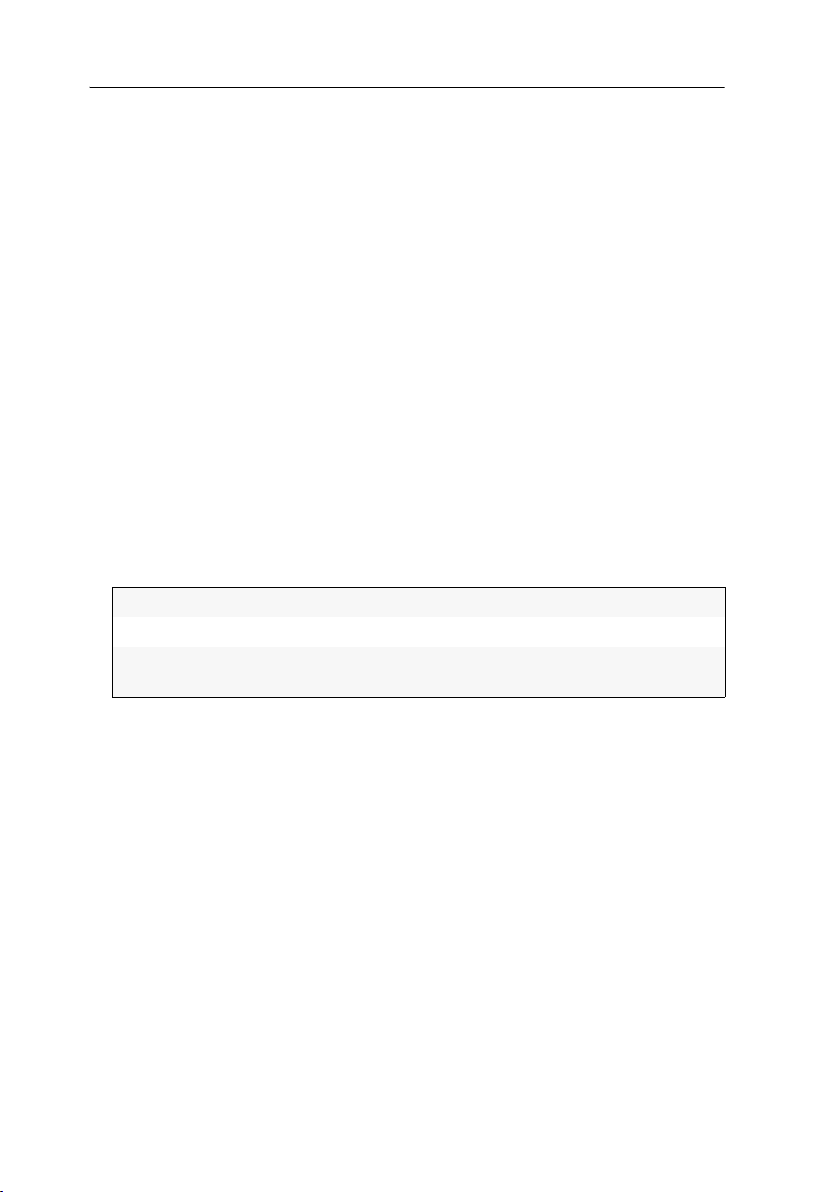
Users and Groups
Renaming the user account
How to rename a user account:
1. Click on User area > User in the tree view.
2. Right-click the user account to be edited and click the Configuration entry in the
context menu.
3. Enter the new username in the Name entry.
4. Optional: Enter the user’s full name in the Full name entry
5. Click OK to save your settings.
Changing the user account password
How to change the user account password:
1. Click on User area > User.
2. Right-click the user account to be edited and click the Configuration entry in the
context menu.
3. Click on Change password.
4. Change the following data within the entry mask:
New password:
Confirm password:
Clear text:
Enter the new password.
Repeat the new password.
Mark this entry to view and control both entered passwords.
5. Click OK to save the new password.
6. Click OK to save your settings.
66 · G&D DVICenter

Users and Groups
Changing the user account rights
Any user account can be assigned with different rights.
The following table lists the different user rights. Further information on the rights
can be found on the indicated pages.
Name Right Page
Change own password
Mouse reset
Multi access
Personal profile
Push-Get rights
Superuser right
Target access rights
Target config
Target group
access rights
Target multi access
rights
Target USB access
Target (group)
USB access rights
Target power
group rights
Target power rights
WebIf login
Change own password page 73
Reset or reactivate PS/2 mouse page 89
Access type when a target computer is simulta-
page 86
neously accessed
Change personal user settings page 154
Carry out Push-Get function page 156
Unrestricted access to the configuration of the
page 72
system
Access to a target module page 84
Configuration of target modules page 89
Access to a target group page 85
Access if a target computer is accessed by
page 86
several users
Access USB devices for all target computers page 88
Access USB devices for a certain target module
page 88
or target group
Switch power outlets of a target group page 134
Switch power outlets of a target module page 133
Login to the Config Panel web application page 72
G&D DVICenter · 67

Users and Groups
Changing a user account’s group membership
NOTE:
Any user within the system can be a member of up to 20 user groups.
How to change a user account’s group membership:
1. Click on the User area > User groups entries in the tree view.
2. Right-click the user group to be edited and click the Configuration entry in the context menu.
3. Click the Members tab.
Now you can easily add members to or delete them from any user group.
The window consists of two tables. These tables list the user accounts of the
KVM matrix system:
Unassigned:
Assigned group
members:
lists all user accounts that are not assigned to this group
lists all user accounts that are assigned to this group
4. Mark the user account you want to add to or delete from the group.
5. Click the button (right arrow) to add the user account to the group or the button (left arrow) to delete it from the list.
Enabling/Disabling a user account
IMPORTANT:
system.
How to enable/disable a user account:
1. Click on the User area > User groups entries in the tree view.
2. Right-click the user account you want to enable/disable and click the Configuration
entry in the context menu.
3. Click the Enabled entry to enable the user account.
Disable the entry if you want to lock the access to the system for this user account
4. Click the OK button to save your settings.
If the user account is disabled, the user has no access to the KVM
68 · G&D DVICenter
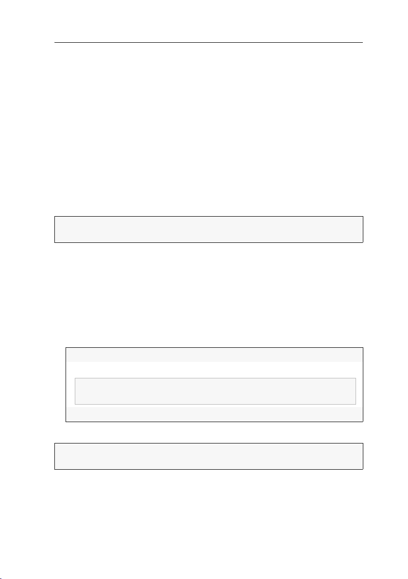
Users and Groups
NOTE:
If the user group is disabled, the group rights do not apply to the
assigned members.
Deleting a user account
How to delete a user account:
1. Click on the User area > User groups entries in the tree view.
2. Right-click the user account you want to delete and click the Delete entry in the
context menu.
3. Click OK to confirm the confirmation prompt.
Administrating user groups
User groups enable the user to create a common rights profile for several users with
the same rights and to add user accounts as members of this group.
This way, the rights of these user accounts do not have to be individually configured, which facilitates the rights administration within the KVM system.
NOTE:
The administrator and any user with the Superuser right are authorised to
create and delete user groups as well as edit the rights and the member list.
Creating a new user group
The user can create up to 256 user groups within the system.
How to create a new user group:
1. Click on the User area > User groups entries in the tree view.
2. Right-click the display range and click the New entry in the context menu.
3. Enter the following data in the entry mask:
Name:
Enabled:
Comment:
4. Click OK to save your settings.
IMPORTANT:
rights within the system
Enter the name of the user group.
Activate this entry to enable the user group.
If necessary, enter a comment regarding the user group.
Directly after the new user group has been created, it contains no
G&D DVICenter · 69

Users and Groups
Renaming a user group
How to rename a user group:
1. Click on the User area > User groups entries in the tree view.
2. Right-click the user account you want to rename and click the Configuration entry
in the context menu.
3. Use the Name entry to enter the new name of the user group.
4. Click OK to save your settings.
Changing the user group rights
The various user groups can be assigned with different rights.
The following table lists the different user rights. Further information about the
rights is given on the indicated pages
Name Right Page
Change own password
Mouse reset
Multi access
Personal profile
Push-Get rights
Superuser right
Target access rights
Target config
Target group
access rights
Target multi access
rights
Target USB access
Target (group)
USB access rights
Target power
group rights
Target power rights
WebIf login
Change own password page 73
Reset or reactivate PS/2 mouse page 89
Access type when a target computer is simulta-
page 86
neously accessed
Change personal user settings page 154
Carry out Push-Get function page 156
Unrestricted access to the configuration of the
page 72
system
Access to a target module page 84
Configuration of target modules page 89
Access to a target group page 85
Access if a target computer is accessed by
page 86
several users
Access USB devices for all target computers page 88
Access USB devices for a certain target module
page 88
or target group
Switch power outlets of a target group page 134
Switch power outlets of a target module page 133
Login to the Config Panel web application page 72
70 · G&D DVICenter
Users and Groups
Administrating user group members
How to administrate user group members:
1. Click on the User area > User groups entries in the tree view.
2. Right-click the user group to be edited and click the Configuration entry in the con-
text menu.
3. Click the Members tab.
Members can now easily be added to or deleted from the user groups.
The window consists of two tables. These tables list the user accounts of the
KVM system:
Unassigned:
Assigned group
members:
lists all user accounts that are not assigned to this group
lists all user accounts that are assigned to this group
4. Mark the user account you want to add to or delete from the group.
5. Mark the user account you want to add to or delete from the group. Now click
button (right arrow) to add the user account to the group or the button
the
(left arrow) to delete it from the list.
(De)activating a user group
How to (de)activate a user group:
1. Click on the User area > User groups entries in the tree view.
2. Right-click the user group you want to (de)activate and click the Configuration
entry in the context menu.
3. Activate the Enabled entry to activate the user group.
If you want to lock the access to the KVM system for members of this user group,
deactivate the entry.
4. Click the OK button to save your settings.
Deleting a user group
How to delete a user group:
1. Click on the User area > User groups entries in the tree view.
2. Right-click the user group you want to delete and click the Delete entry in the con-
text menu.
3. Confirm the confirmation prompt by clicking Yes or cancel the process by
clicking No.
G&D DVICenter · 71

Users and Groups
System rights
Rights for full access (Superuser)
The Superuser right enables you to fully access and configure the KVM system.
NOTE:
The information about the user rights, which have been assigned before,
are still stored when the Superuser right is activated. After the Superuser right has
been withdrawn, the saved rights do apply again.
How to change the Superuser right:
1. If you want to change this right of a user account, click the User area > Users entries
in the tree view.
For changing the rights for a user group, click the User area > User groups entries.
2. Right-click the user account or the user group you want to configure and click the
Configuration entry in the context menu.
3. Click the System rights tab.
4. Use the Superuser entry to select between the following options:
Yes:
allows full access to the KVM system and the connected devices
No:
denies full access to the KVM system and the connected devices
5. Click OK to save your settings.
Changing the login right to the web application
How to change the login right to the web application:
1. If you want to change this right of a user account, click the User area > Users entries
in the tree view.
For changing the rights for a user group, click the User area > User groups entries.
2. Right-click the user account or the user group you want to configure and click the
Configuration entry in the context menu.
3. Click the System rights tab.
4. Use the Web Interface Login entry to select between the following options:
Yes:
enables access to web application
No:
denies access to web application
5. Click OK to save your settings.
72 · G&D DVICenter

Users and Groups
Rights to change your own password
How to change the right to change your own password:
1. If you want to change this right of a user account, click the User area > Users entries
in the tree view.
For changing the rights for a user group, click the User area > User groups entries.
2. Right-click the user account or the user group you want to configure and click the
Configuration entry in the context menu.
3. Click the System rights tab.
4. Use the Change own password entry to select between the following options:
Yes:
No:
allows the user to change the user account password
denies the user to change the user account password
5. Click OK to save your settings.
G&D DVICenter · 73

The »KVM combinations« folder
The »KVM combinations« folder
The KVM combinations folder enables you to group different devices in any folders.
Especially in larger system, this folder provides better orientation.
The devices can be grouped according to locations (e. g. server room) or other features (e. g. the operating system of the connected computer).
ADVICE:
or an extender – can be grouped within one folder.
The devices of different classes – e.g. the target modules of a matrix system
Folder administration
The KVM combinations folder provides the following system folders:
[Unassigned]:
[All devices]:
NOTE:
You cannot delete or rename system folders.
Creating new folders
How to create an empty folder:
1. Right-click on KVM combination in the tree view and click on New folder in the con-
text menu.
ADVICE:
click on
2. Use the Name entry to enter the desired name.
3. Optional: Use the Comment entry to enter a comment.
4. Click OK to create the folder.
If you want to create a subfolder, right-click the main directory and
New folder.
This folder lists all devices that are not assigned to any KVM
combination.
This folder lists all devices of the KVM system.
74 · G&D DVICenter

The »KVM combinations« folder
Assigning a device to a folder
NOTE:
Each device can be listed in any number of subfolders.
How to group the connected devices in a new folder:
1. Click on KVM combinations > [All devices] in the tree view.
2. Right-click a connected device and click on Group connected devices in the context
menu.
3. Use the Name entry to enter the desired name.
4. Optional: Use the Comment entry to enter a comment.
5. Click OK to group the devices in the new folder.
How to assign a device to an existing folder:
1. Click on KVM combinations > [All devices] in the tree view.
2. Right-click the device to be assigned and click on Copy device in the context menu.
3. Open the folder to which the device is to be assigned to.
4. Right-click the main view and click on Paste device in the context menu.
Deleting a device from a folder
A device can be deleted from the folder by moving it to the [Unassigned] group or by
selecting the
Remove from folder entry in the context menu.
How to cancel a target module’s assignment to a folder:
1. Click on KVM combinations > [All devices] in the tree view.
2. Open the folder to which the device is assigned to.
Right-click the device whose assignment you want to delete and click on
Remove from folder in the context menu.
G&D DVICenter · 75

The »KVM combinations« folder
Renaming a folder
How to rename a folder:
1. Click on KVM combinations > [All devices] in the tree view.
2. Right-click the folder to be renamed and click on Rename folder in the context menu.
3. Edit the name and press Enter.
Deleting a folder
Any created folders can be deleted at any time.
If a folder contains devices while it is deleted, these devices are automatically moved
to the [Unassigned] group.
NOTE:
The system folders [Unassigned] and [All devices] are administrated by the web
application and cannot be deleted.
How to delete a folder:
1. Click on KVM combinations > [All devices] in the tree view.
2. Right-click the folder to be deleted and click on Delete folder in the context menu.
NOTE:
You can select several folders by pressing Shift, Ctrl and the left mouse
key at the same time.
3. Confirm the security request by clicking Yes or cancel the task by clicking No.
76 · G&D DVICenter

Advanced functions of the KVM system
Advanced functions of the KVM system
Temporarily (de)activating SNMP traps (Maintenance mode)
By activating the maintenance mode, the user is enabled to deactivate SNMP traps
(see page 53), e.g. for devices that are occupied for reasons of maintenance.
The status messages are displayed again after the maintenance mode has been deactivated.
(De)activating the maintenance mode
How to (de)activate a device’s maintenance mode:
1. Use the tree view to click on KVM matrix systems > [name] > Matrix switches.
2. Right-click the device and click on
Maintenance > On or Maintenance > Off in the context menu.
Viewing a list of devices in maintenance mode
How to display the list of devices in maintenance mode:
1. Click on the System monitoring > Maintenance folders in the tree view.
The main view lists the respective devices.
ADVICE:
The devices in Maintenance mode are always displayed in yellow.
Identifying a device by activating the Identification LED
Some devices provide an Identification LED on the front panel.
Use the web application to switch the device LEDs on or off in order to identify the
devices in a rack, for example.
How to (de)activate the Identification LED of a device:
1. Use the tree view to click on KVM matrix systems > [name] > Matrix switches.
2. Right-click the device and click on
Identification LED > On or Identification LED > Off in the context menu.
G&D DVICenter · 77
Advanced functions of the KVM system
Saving and restoring the data of the KVM system
The backup function lets you save your configurations. You can reset your configurations with the restore function.
NOTE:
To save and restore your configuration, you can go to System > Tools in the
directory tree or use the
How to save the configuration of the KVM system:
1. In the directory tree, click on System > Tools.
2. Click Backup.
3. Enter the location and the name of the backup file under Path.
Tools icon.
ADVICE:
Use the file button to select the name and the location of the backup
file via the file dialog.
4. Optional: Enter a Password to secure the backup file or a Comment.
5. Select the scope of data you want to back up: You can back up either the network
settings and/or the Application settings.
6. Click Backup.
How to restore the configuration of the KVM system:
1. In the directory tree, click on System > Tools.
2. Click on Restore.
3. Enter the location and the name of the backup file under Path.
ADVICE:
Use the file button to select the name and the location of the backup
file via the file window.
4. Use the information given under Creation date and Comment to check if you selected
the right backup file.
5. Select the scope of data you want to restore: You can restore either the network set-
tings and/or the Application settings.
NOTE:
If one of these options cannot be selected, the data for this option was
not stored.
6. Click Restore.
7. Click OK to close the window.
78 · G&D DVICenter

Advanced functions of the KVM system
Administration and use of EDID profiles
The EDID information (Extended Display Identification Data) of a monitor inform the
graphics card of a connected computer about various technical features of the
device.
The EDID profile of the monitor that is connected to the user module is not available at the target module. Therefore, the target module transmits a standard profile to
the computer. The EDID information of this profile are optimised for the majority
of available graphics cards.
ADVICE:
sole monitor (see page 95) and activate the configuration of the target module
afterwards.
We provide additional profiles for special resolutions.
In some cases it is recommended to read out the EDID profile of the con-
Importing the EDID profile of a monitor
NOTE:
An EDID profile can either be imported from a bin file or directly from a
monitor that is connected to the KVM switch.
How to import the EDID profile of a connected monitor:
1. Click on System > Edid profiles in the tree view.
2. Right-click in the display area and click on New in the context menu.
3. Click on Learn.
4. Mark the user module to which the monitor whose EDID information you want
to import is connected.
NOTE:
Click the [+] icon to display a list of all user modules that are connected
to the matrix switch.
5. Click Ok.
NOTE:
The Name and Comment entries are automatically filled out and the con-
tents of the EDID information is displayed.
6. If desired, change the information in the Name and/or Comment entries.
7. Click OK to save your settings.
G&D DVICenter · 79
Advanced functions of the KVM system
How to import the EDID profile of a monitor from a file:
1. Click on System > Edid profiles in the tree view.
2. Right-click in the display area and click on New in the context menu.
3. Click on Search.
4. Use the file dialogue to choose the bin file you want to import and click on Open.
NOTE:
The Name and Comment entries are automatically filled out and the con-
tents of the EDID information is displayed.
5. If desired, change the information in the Name and/or Comment entries.
6. Click OK to save your settings.
Overview of the stored EDID profiles
The System > Edid profiles branch of the tree view provides an overview of the EDID
profiles that are stored within the KVM system.
Use the context menu the Add or Delete and Change the profiles added by the user.
NOTE:
Add, Delete and Change the profiles as described on the previous pages.
NOTE:
Information on choosing and enabling an EDID profile for a particular
video channel is given on
page 82.
Activating the premium functions
After a premium function has been purchased, the user receives a feature key. This file
contains a key to activate the purchased function(s).
The premium function(s) is/are activated by importing this key to the web application.
How to import a feature key to activate the purchased function(s):
1. Use the tree view to click on KVM matrix systems > [name] > Matrix switches.
2. Right-click the device whose feature key is to be imported.
3. Click the Configuration entry in the context menu.
4. Click the Features tab.
5. Click on Import feature key from file... and import the feature key (file) via the file
interface.
After the file has been loaded, the clear text of the feature key is displayed in the
text field.
NOTE:
The clear text of the feature key can also be copied into the text field.
6. Click OK to close the window.
80 · G&D DVICenter

Overview of the monitoring values
Overview of the monitoring values
The device-specific branches as well as the KVM combinations and the Critical devices
branch of the tree view enable you to view information on the current status of the
different devices in the KVM system.
The following pages list the various monitoring values of different devices.
Matrix switches
Feature Status Meaning
Current Numerical value Power consumption (Ampere)
Fan speed Numerical value Fan speed (rpm)
Main power Off »Main power« power pack does not supply power.
On Power supply via »Main power« power pack
Network A|B Down No conenction to network
Up Connection to network established
Redundant power On Power is supplied via »Red. power« power pack
Off No power is supplied via »Red. power« power pack
Status Offline Device is turned off.
Online Device is turned on
Temperature Numerical value Current temperature (°C) in the device
Voltage [Value] electric voltage (Volt)
G&D DVICenter · 81

Overview of the monitoring values
User modules
Feature Status Meaning
Display Type [String] Textual description of connected monitor, derived
Main Power Off Main power supply disconnected
On Main power supply established
PS/2 Keyboard PS/2 keyboard of console is ready for operation
K/M PS/2 keyboard and mouse of the console are ready
Mouse PS/2 mouse of the console is ready for operation
None No PS/2 devices detected at console
Redundant Power Off Redundant power supply disconnected
On Redundant power supply established
Status Offline The user module is not connected or turned off.
Online The user module is connected and turned on.
Temperature Numerical value Current temperature (°C) in the device
USB Keyboard USB keyboard of the console is ready for operation
K/M USBeyboard and mouse of the console are ready for
Mouse USB mouse of the console is ready for operation
None No USB devices detected at console
from EDID data
for operation
operation
82 · G&D DVICenter

Overview of the monitoring values
Target modules
Feature Status Meaning
CPU PS/2 Keyboard Connection between computer and emulator for
K/M Connection between computer and emulator for
Mouse Connection between computer and emulator for
None No Connection between computer and PS/2 emulator
CPU USB K/M Disconnected Connection between computer and
Connected No connection between computer and
Initialized Connection between computer and
Status Offline The target module is not connected or turned off.
Online The target module is connected and turned on.
Temperature Numerical value Current temperature (°C) in the device
Video cable Connected Connection to video output of computer and target
Disconnected No connection to video output of computer and tar-
Video signal None No video signal detected
SL-DVI DVI signal detected (Single-Link)
DP DisplayPort signal detected
PS/2 keyboard established
PS/2 keyboard and mouse established
PS/2 mouse established
USB HID emulation established
USB HID emulation
USB HID emulation initialised
module established
get module or computer is turned off.
G&D DVICenter · 83

2
You can use the KVM matrix systems in the directory tree of the web application to
configure various settings of the matrix switches and the connected devices.
The following pages provide a detailed description of these settings.
Matrix Systems
Target modules
Target modules connect target computers to the KVM matrix system and can be
accessed with user modules.
Adjusting access and configuration rights
Accessing a target module
ADVICE:
(see page 70).
This way, it is easier to keep an overview of the KVM matrix system. It also benefits
the operating performance within the system’s on-screen display.
In order to execute particular user settings which deviate from existing target groups,
you can assign users with individual access rights in addition to group rights.
How to change target access rights:
1. In the directory tree, click User area > Users.
2. Right-click the user account or the user group you want to configure and click the
3. Click the Matrix systems > Individual Device Rights tabs.
4. Choose the desired target module in the list on the left side of the window.
We recommend using target groups to help assign all target access rights
If you want to change the rights for user groups, click User area > User groups.
Configuration entry on the context menu.
ADVICE:
in the selection window.
Use the drop-down menu to choose the target module to be displayed
84 · G&D DVICenter
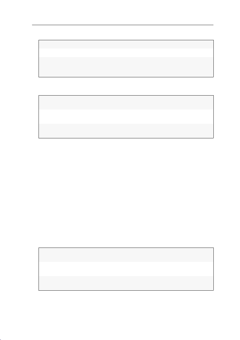
You can choose between the following options:
Target modules
[All targets]
[Unassigned]
Search...
Lists all target modules within the system
Only lists [Unassigned] target modules
After you choose this option, another window opens.
Choose the desired View filter in the tree to display only the
devices which are assigned to this view filter.
5. Use the Access entry on the right-hand side of the window to select between the
following options:
No:
Denies access to the computer that is connected to the target
module
View:
Allows users to view the screen content of the computer that is
connected to the target module
Full:
Allows full access to the computer connected to the target
module
6. Repeat steps 4 and 5 if you want to change the access rights for other target modules.
7. Click OK to save your settings.
Accessing target groups
How to change the target group access right:
1. In the directory tree, click User area > Users.
If you want to change the rights for user groups, click User area > User groups.
2. Right-click the user account or the user group you want to configure and click the
Configuration entry on the context menu.
3. Click the Matrix systems > Device Group Rights tabs.
4. Choose the desired target module in the list on the left side of the window.
5. Use the Access entry on the right-hand side of the window to select between the
following options:
No:
Denies access to a target computer which is already accessed by
another user
View:
Screen contents of a target computer that is already accessed by
another user can be viewed; inputs are not possible
Full:
Allows full access to a target computer that is already accessed
by another user
6. Repeat steps 4 and 5 to change the access rights for further target modules.
7. Click OK to save your settings.
G&D DVICenter · 85
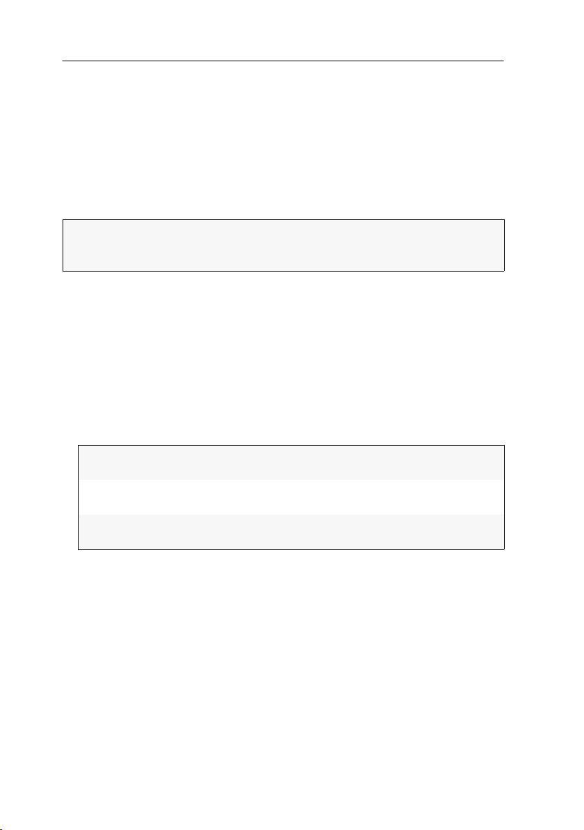
Target modules
Access mode if a target computer is accessed by several users
Only one user can access a target computer in the default settings of the KVM
matrix system.
This restriction can be lifted by changing the access rights for a user account or a
user group.
You can either change the global settings to allow several users to access a target
computer at the same time (for all target computers a user or a user group has access
to) or you can change the rights for particular target computers or target groups only.
NOTE:
The right for simultaneous access depends on the user’s effective right (see
page 63). The effective right is the highest right that results from the individual
right of the user accounts and the rights of the assigned group(s).
How to change the rights to access all target computers at the same time:
1. In the directory tree, click User area > Users.
If you want to change the rights for user groups, click User area > User groups.
2. Right-click the user account or the user group you want to configure and click the
Configuration entry on the context menu.
3. Click the Matrix systems and Global Device Rights tabs.
4. Use the Multi Access entry in the Access Rights column to choose between the fol-
lowing options:
No:
Denies access to a target computer which is already accessed by
another user
View:
Screen contents of a target computer that is already accessed by
another user can be viewed; inputs are not possible
Full:
Allows full access to a target computer that is already accessed by
another user
5. Click OK to save your settings.
86 · G&D DVICenter

Target modules
How to change the rights to access a certain target module or group at the same time:
NOTE:
Several users are only allowed to access the target at the same time if the
user account or the user group hold the general access rights
(see page 84 f.) for the
target computer!
1. In the directory tree, click User area > User.
If you want to change the right for user groups, click User area > User groups.
2. Right-click the user account or user group you want to configure and click Configu-
ration on the context menu.
3. Click the Matrix systems tab.
4. If you want to change the access rigths for a certain target module, click on
Individual Group Rights.
If the rights should apply for a target group, click on Device Group Rights.
5. Choose your desired target module or target group from the list on the left side.
ADVICE:
Use the drop-down menu to choose the target modules to be dis-
played in the selection screen:
[All targets]: Lists all target modules within the system
[Unassigned]: Only lists [Unassigned] target modules
Search... After you have chosen this option, a new window opens. Choose
the desired View filter in the tree to display only the devices which are assigned
to this view filter.
6. Use the Multi access rights entry on the right-hand side of the window to choose
between the following options:
No:
Denies access to a target computer (of a group) which is already
accessed by another user
View:
Screen contents of a target computer (of a group) that is already
accessed by another user can be viewed; inputs are not possible
Full:
Allows full access to a target computer (of a group) that is
already accessed by another user
7. Click Ok to save you settings.
G&D DVICenter · 87

Target modules
Access to USB devices
In the defaults of the matrix system, users have access to USB devices of a channel
group.
This right can be denied by changing the right »Access to USB devices« of a user
account or a user group.
The right to access USB devices of a certain target computer can be denied either
globally (for all target computers a user or a user group can access) or for certain tar
get computers or groups.
NOTE:
The access right depends on the user’s effective right (see page 63). The
effective right is the highest right that results from the individual right of user
accounts and the rights of assigned group(s).
How to change the right to access USB devices for all target computers:
1. In the directory tree, click User area > User.
If you want to change the right for user groups, click User area > User groups.
2. Right-click the user account or user group you want to configure and click Configu-
ration on the context menu.
3. Click the tabs Matrix systems and Global device rights.
4. Under Access rights > Access to USB devices, choose between the following options:
-
Yes:
No:
Allow access to USB devices of the channel group.
Deny access to USB devices of the channel group.
5. Click Ok to save you settings.
How to change the right to access USB devices for a certain target module or target group:
NOTE:
You can configure and apply access to USB devices if the user account or
the user group are assigned with general access rights
(see page 84 f.) for the target
computer.
1. In the directory tree, click User area > User.
If you want to change the right for user groups, click User area > User groups.
2. Right-click the user account or user group you want to configure and click
Configuration on the context menu.
3. Click the Matrix systems tab.
4. If you want to change the access rights for a certain target module, click on
Individual Group Rights. If the rights should apply for a target group, click on Device
Group Rights.
88 · G&D DVICenter

Target modules
5. Choose the target module or the target group in from the list on the left-hand side.
IMPORTANT:
The right to access USB devices is configured for the target module,
which provides the main KVM channel of the channel group. The USB channel is
assigned to the same channel group.
ADVICE:
Use the drop-down menu to choose the target modules to be dis-
played in the selection screen:
[All targets]: Lists all target modules of the system
[Unassigned]: Only lists [Unassigned] target modules
Search... Choosing this option opens a new window. Choose the desired View
filter in the directory tree to display only the devices which are assigned to
this view filter
.
6. Under USB access during grouping on the right-hand side, you can choose between
the following options:
Yes:
No:
Allow access to USB devices of the channel group.
Deny access to USB devices of the channel group.
7. Click Ok to save you settings.
Changing the rights to configure the target modules
How to change the rights to view and edit the configuration of the target modules:
1. In the directory tree, click User area > User.
If you want to change the rights for user groups, click User area > User groups.
2. Double-click the user account or the user group you want to configure.
3. Click the Matrix systems > Global Device Rights tabs.
4. Use the Target config entry to choose between the following options:
Yes:
No:
Allows the user to view and edit the target module config
Denies the user to view and edit the target module config
5. Click OK to save your settings.
Changing the rights to reset or reactivate a PS/2 mouse
Compared to USB mouses, PS/2 mouses do not support hot plug technology. You
can therefore insert the PS/2 plug during operation, but it may be possible that the
computer does not detect the input device.
In order to activate or reset the PS/2 mouse, the matrix system can be used to send
a special command to the computer connected to the target module.
G&D DVICenter · 89

Target modules
How to change the rights to reset or reactivate the PS/2 mouse:
1. In the directory tree, click User area > User.
If you want to change the rights for user groups, click User area > User groups.
2. Right-click the user account or the user group you want to configure and click
Configuration on the context menu.
3. Click Matrix systems > Global Device Rights.
4. Use the Mouse reset entry to choose between the following options:
Yes:
No:
5. Press OK to save your settings.
Allows the user to reset or reactivate the PS/2 mouse interface of a
target computer
Denies the user to reset or reactivate the PS/2 mouse interface of a
target computer
Basic configuration of target modules
Renaming target modules
During the start-up of the KVM matrix system, target modules are automatically
named.
How to rename target modules:
1. In the directory tree, click KVM matrix systems > [Name] > Target modules.
2. Right-click the target module and click Configuration on the context menu.
3. Enter the name of the target module into the Name entry.
4. Press OK to save your settings.
Changing comments of target modules
In addition to the target module name, the list field of the web application also displays a comment regarding this target module.
ADVICE:
for example.
Use the comment to write down the location of the target module down,
How to change comments of target modules:
1. In the directory tree, click KVM matrix systems > [Name] > Target modules.
2. Right-click the target module and click Configuration on the context menu.
3. Enter any comment into the Comment entry.
4. Press OK to save your settings.
90 · G&D DVICenter

Target modules
Deleting target modules from the KVM matrix system
If the KVM matrix system is not able to detect a target module, which already had been
connected to the system, the device is considered inactive. Delete the list entry of the tar
get module manually if you want the device to be permanently remove from the system.
NOTE:
Only switched-off target modules can be deleted.
How to delete target modules that are switched off or disconnected from the system:
1. In the directory tree, click KVM matrix systems > [Name] > Target modules.
2. Right-click the target module you want to delete and click Delete on the context
menu.
3. Confirm the confirmation prompt by clicking Yes or cancel the process by
clicking No.
Copying the target module config settings
If a target module of the KVM matrix system is replaced by another device, the previous config settings can be copied to the new device. After the config settings have
been copied to the new device, it can be operated immediately.
-
IMPORTANT:
want to copy is deleted from the KVM matrix system.
How to copy target module config settings:
1. In the directory tree, click KVM matrix systems > [Name] > Target modules.
2. Right-click the new target module and click the Move to... entry on the context menu.
A new window shows a list of all inactive or deleted target modules.
3. Choose the target module whose configuration settings you want to copy.
4. Click OK to copy the configuration settings.
After this task is carried out, the target module whose settings you
Settings for special hardware
Selecting the USB keyboard mode
NOTE:
This setting can only be edited with USB versions of the target modules.
USB target modules support different USB input devices. You can use the special features of a USB input device after selecting the specific USB keyboard mode (see
page 93).
G&D DVICenter · 91

Target modules
As an alternative to the specific USB keyboard modes, you can use the Generic HID
mode. In this mode, the data from the USB devices connected to the top Keyb./Mouse
interface is transmitted to the active target module.
IMPORTANT:
The Generic HID mode supports many common HID devices. How-
ever, the operation of any particular HID devices in Generic HID mode cannot be
guaranteed.
IMPORTANT:
When connecting a USB hub or a USB composite device containing
multiple USB devices, only the first of the connected HID devices can be used in
Generic HID mode (see page 104).
the
USB keyboards: In addition to the keys of standard keyboard layouts, the default
USB keymode
PC Multimedia supports several multimedia keys like Loud and Quiet.
With Apple or Sun Keyboards, you can apply special keymodes to use the special keys
of these keyboards.
The following table lists the supported USB keyboards:
INPUT DEVICE SETTING
PC keyboard with additional multimedia keys PC Multimedia
PC keyboard with standard keyboard layout PC Standard
Apple Keyboard with numeric keypad (A1243) Apple A1243
Sun Keyboard (German keyboard layout) SUN German
Sun Keyboard (American keyboard layout) SUN US
Displays and tablets: You can operate computers connected to the target module with
one of the supported displays or tablets:
INPUT DEVICE SETTING
HP 2310t HP 2310t
iiyama T1931 iiyama T1931
NOTTROT N170 KGE NOTTROT N170 KGE
Wacom Cintiq 21UX Wacom Cintiq 21UX
Wacom Intuos3 Wacom Intuos3
Wacom Intuos4 S Wacom Intuos4 L
Wacom Intuos4 M Wacom Intuos4 M
Wacom Intuos4 L Wacom Intuos4 S
Wacom Intuos4 XL Wacom Intuos4 XL
Wacom Intuos5 S Wacom Intuos5 S
Wacom Intuos5 M Wacom Intuos5 M
Wacom Intuos5 L Wacom Intuos5 L
92 · G&D DVICenter

Target modules
Generic HID mode: In this mode, the data from the USB devices connected to the
top Keyb./Mouse interface is transmitted to the active target module.
INPUT DEVICE SETTING
Any USB device Generic HID
IMPORTANT:
The Generic HID mode supports many common HID devices. How-
ever, the operation of any particular HID devices in Generic HID mode cannot be
guaranteed.
IMPORTANT:
To use a generic HID device, you need to activate the Generic HID sup-
port of the user module to which the USB device is connected to (see page 104).
Controller: With ShuttlePRO v2 multimedia controllers, you can operate audio and
video programs. You can use a special USB keymode to operate computers con
nected to the target module using the controller:
INPUT DEVICE SETTING
Contour ShuttlePRO v2
LK463 compatible keyboard: You can connect an LK463 compatible keyboard to the
Contour SP2
user modules of the KVM matrix system. The order of the 108 keys of these keyboards
is the same as the OpenVMS keyboard layout.
A special USB keyboard mode guarantees that the keypress of a special key on this
keyboard is forwarded to the target computer:
INPUT DEVICE SETTING
LK463 compatible keyboard
LK463
How to select a USB keyboard mode:
1. In the directory tree, click KVM matrix systems > [Name] > Target modules.
2. Right-click the target module you want to configure and click on Configuration on
the context menu.
3. Select a setting under USB HID Mode (see table on page 92):
-
NOTE:
Update the firmware of both the matrix switch and the user module if the
web application does not show all keyboard modes.
4. Click OK to save your settings.
IMPORTANT:
After changing the keyboard layout of Sun Keyboards, Sun computers
require a reboot.
G&D DVICenter · 93

Target modules
How to use the special function of Sun keyboards on a standard keyboard:
IMPORTANT:
You can use the emulation of »Solaris Shortcut Keys« in the SUN German
and SUN US keyboard mode only.
If the target module is provided with a Sun Keyboard, you can use Solaris Shortcut Keys
after enabling their support.
When using a standard keyboard, you can perform these functions by using the key
combinations listed below
KEY COMBINATIONS »SOLARIS SHORTCUT KEY« OF SUN KEYBOARDS
Ctrl+Alt+F2 Again
Ctrl+Alt+F3 Props
Ctrl+Alt+F4 Undo
Ctrl+Alt+F5 Front
Ctrl+Alt+F6 Copy
Ctrl+Alt+F7 Open
Ctrl+Alt+F8 Paste
Ctrl+Alt+F9 Find
Ctrl+Alt+F10 Cur
Ctrl+Alt+F11 Help
Ctrl+Alt+F12 Mute
Ctrl+Alt+NUM+ Loud
Ctrl+Alt+NUM- Quiet
Ctrl+Alt+NUM* Compose
Ctrl+Alt+Pause Shutdown
Pause+A Stop
:
Support for servers of IBM’s RS/6000 series
NOTE:
This setting can only be edited with PS/2 versions of the target modules.
Enable the support for UNIX servers of IBM’s RS/6000 series if the target computer
is such a server.
How to (de)activate the special support for servers of IBM’s RS/6000 series:
1. In the directory tree, click KVM matrix systems > [Name] > DVI-CPUs.
2. Right-click the target module you want to configure and click the Configuration
entry on the context menu.
94 · G&D DVICenter
Target modules
3. Use the IBM RS/6000 support entry to choose between the following options:
yes:
no:
Support for servers of IBM’s RS/6000 series is activated
Support for servers of IBM’s RS/6000 series is deactivated
4. Click OK to save your settings.
Defining the EDID profile to be used
The EDID information (Extended Display Identification Data) of a monitor inform the
graphics card of a connected computer about various technical features of the device.
The EDID profile of the monitor, which is connected to the user module, is not
available at the target module. Therefore, the target module transmits a standard
profile to the computer. The EDID information of this profile are optimised for the
majority of available graphics cards.
We provide additional profiles for special resolutions.
ADVICE:
monitor
How to choose the EDID profile to be transmitted to the computer:
1. In the directory tree, click KVM Matrixsystems > [Name] > Target modules.
2. Right-click the target module you want to configure and click on Configuration on
3. Use the EDID entry to select between the standard profile (Device specific default pro-
In some cases it is recommended to read out the EDID profile of the console
(see page 79) and activate the configuration of the target module afterwards.
the context menu.
file) or another profile from the list.
NOTE:
The names of the special G&D profiles provide information on the reso-
lution and refresh rate for the profile.
For example, the GUD DVI1024D4 060 1280×1024/60 profile is provided for a resolution of 1280×1024 pixels at 60 Hz refresh rate.
4. Click OK to save your settings.
Reducing the colour depth of the image data to be transmitted
In the default settings of a target module, the central module transmits the image
information with a maximum colour depth of 24 bit to the user module.
Using a high resolution and displaying moving images can result in the user module
“skipping” several images.
In such cases, reduce the colour depth if the image data to 18 bits, which reduces the
data volume to be transmitted.
NOTE:
Depending on the image contents, reducing the colour depth may result in
slight colour grades.
G&D DVICenter · 95
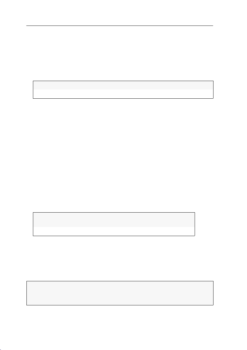
Target modules
How to change the colour depth of the image data you want to transmit:
1. In the directory tree, click KVM Matrixsystems > [Name] > Target modules.
2. Right-click the target module you want to configure and click on Configuration on
the context menu.
3. Use the Colour depth entry of the Target module configuration paragraph to choose
between the following options:
24 Bit:
18 Bit:
4. Click OK to save your settings.
transmits the image data with a maximum colour depth of 24 bits
reduces the colour depth of image data to 18 bits
Enhanced functions
Enabling/disabling the keyboard signal
By default, the signals of mouse and keyboard connected to the user module are
transmitted to the target module.
The settings of the target module let you enable or disable the transmisison of the
keyboard signal.
How to enable/disable the transmission of the keyboard signal:
1. In the directory tree, click KVM matrix systems > [Name] > Target modules.
2. Right-click the target module you want to configure and click on Configuration on
the context menu.
3. Under Keyboard support, select one of the following options:
Enabled:
Disabled:
4. Click OK to save your changes.
»Multiuser« display
If several users are accessing a target computer (Multiuser mode), the »Multiuser«
information can be activated. This way, all accessing users are provided with the
information that at least one other user is currently accessing the target computer.
Keyboard signals are transmitted to the target module
(default)
Keyboard signals are not transmitted to the target module.
NOTE:
The setting to display this information is usually configured for the entire
system and individually for each user account.
Both options are described on this page.
96 · G&D DVICenter
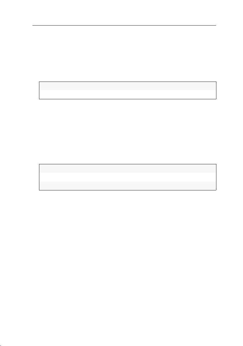
Target modules
How to enable or disable the »Multiuser« information for the entire system:
1. In the directory tree, click KVM matrix systems > [Name] > Matrix switches.
2. Right-click the master matrix switch and click the Configuration entry on the con-
text menu.
3. Use the Multiuser display entry in the Configuration column to choose between the
following options:
Yes:
No:
Enables the »Multiuser« display
Disables the »Multiuser« display
4. Click OK to save your settings.
How to (de)activate the »Multiuser« information for a particular user account:
1. In the directory tree, click User area > User.
2. Right-click the user account you want to configure and click the Configuration
entry on the context menu.
3. Click the Matrix system > Personal Profile > Matrix switch tabs and use the
Multiuser display entry to choose between the following options:
system:
on:
off:
global system settings do apply (see above)
displays »Multiuser« information
does not display »Multiuser« information
4. Click OK to save your settings.
Showing the status information of a target module
With the context menu of a target module you can call an interface with various status information of the target module. In addition to the name and the storage location, information regarding the firmware version is displayed.
How to show the status information of a target module:
1. In the directory tree, click KVM Matrix systems > [Name] > Target modules.
2. Right-click the target module whose status information you want to view and
click the
Information entry on the context menu.
G&D DVICenter · 97

Target modules
3. This interface provides the following information:
Name:
Device ID:
Status:
Folder:
Comment:
Firmware name:
Firmware revision:
target module name
physical ID of the target module
current status (on or off) of the target modules
folder to which the target module is assigned to
user comment regarding the target module
firmware name
firmware version
4. Click Close to close the window.
Showing information about the connection
The connection information is the active connection between a user and a target
module. The different cable lengths between two modules of the KVM matrixswitch
are listed separately. This list does not only display the ports used for the cable con
nection but also the medium and the transmittable signals.
How to view the information regarding the connection:
1. In the directory tree, click KVM Matrix systems > [Name] > Target modules.
2. Right-click the target module and click on Active connection on the context menu.
3. The list displays the following information about the different cable lines
between two modules of the KVM matrix switches:
Name and ports of two connected modules
Medium of the cable connection
Information regarding the transmittable signals:
[K]eyboard, [V]ideo, [M]ouse, and [A]udio
-
4. Click Close to close the window.
Viewing the cascade information
The cascade information provides you with an overview of the physical connections
of the KVM matrix system. In addition to the master device, the connected slave
devices as well as the user modules and target modules are displayed.
The cascade information also displays the physical device ID, the connection port at
the KVM matrix system and the status.
98 · G&D DVICenter
 Loading...