


Guntermann & Drunck GmbH
www.gdsys.de
Target Modules and
User Modules
EN
Installation and Operating Guide
Standard variants
A9200136-2.21

About this manual
This manual has been carefully compiled and examined to the state-of-the-art.
G&D neither explicitly nor implicitly takes guarantee or responsibility for the quality, efficiency and marketability of the product when used for a certain purpose that
differs from the scope of service covered by this manual.
For damages which directly or indirectly result from the use of this manual as well
as for incidental damages or consequential damages, G&D is liable only in cases of
intent or gross negligence.
Caveat Emptor
G&D will not provide warranty for devices that:
Are not used as intended.
Are repaired or modified by unauthorized personnel.
Show severe external damages that was not reported on the receipt of goods.
Have been damaged by non G&D accessories.
G&D will not be liable for any consequential damages that could occur from using
the products.
Proof of trademark
All product and company names mentioned in this manual, and other documents
you have received alongside your G&D product, are trademarks or registered trade
marks of the holder of rights.
© Guntermann & Drunck GmbH 2015. All rights reserved.
Version 2.21 – 30/01/2015
Guntermann & Drunck GmbH
Dortmunder Str. 4a
57234 Wilnsdorf
Germany
Phone +49 (0) 2739 8901-100
Fax +49 (0) 2739 8901-120
http://www.GDsys.de
sales@GDsys.de
-
i · Target and user modules

Table of Contents
Table of Contents
Safety instructions ............................................................................................ 1
Chapter 1: Target modules
Target module »DVI-CPU« .............................................................................. 3
Target module »DVI-CPU-UC« ........................................................................ 7
Target module »DVI-CPU-MC2« ................................................................... 11
Target module »DVI-CPU-MC2-UC« ............................................................ 16
Target module »DVI-CPU-Fiber« ................................................................... 22
Target module »DVI-CPU-Fiber-UC« ............................................................ 27
Target module »DP-CPU« .............................................................................. 32
Target module »DP-CPU-UC« ....................................................................... 36
Target module »VGA-CPU-UC« .................................................................... 40
Target module »U2-R-CPU« ........................................................................... 44
Chapter 2: User modules
User module »DVI-CON« ............................................................................... 47
User module »DVI-CON-MC2« ..................................................................... 53
User module »DVI-CON-MC4« ..................................................................... 60
User module »DVI-CON-Fiber« ...................................................................... 68
User module »DVI-CON-2« ........................................................................... 74
User module »DP-CON« ................................................................................ 80
User module »DP-CON-2« ............................................................................. 86
User module »U2-R-CON« ............................................................................. 92
User module »DVI-CON-12V« ....................................................................... 95
User module »DVI-CON-Video« .................................................................. 101
Target and user modules · ii

Table of Contents
Chapter 3: Generic HID
Enabling/disabling the user module’s Generic HID mode ............................ 106
Enabling/disabling the target module’s Generic HID mode .......................... 107
Chapter 4: Extender mode
Opening the on-screen display in extender mode ........................................... 108
Configuration ............................................................................................... 109
iii · Target and user modules

Safety instructions
Safety instructions
Please read the following safety instructions carefully before you start operating the
G&D product. The instructions well help in avoiding damages to the product and in
preventing possible injuries.
Keep this manual handy for all persons who will be using this product.
Follow all warnings or operating instructions which are on the device or stated in
this user manual.
, Beware of electric shocks
To avoid the risk of electric shock, do not open the device or remove the covers.
If service is required, please contact our technicians.
, Disconnect the main power plug or the power supply before installation
Before installation, ensure that the device has been disconnected from the power
source. Disconnect the main power plug or the power supply of the device.
, Ensure constant access to the power plugs
During the installation of the devices, ensure that the power plugs remain accessible.
, Do not cover the ventilation openings
Ventilation openings prevent the device from overheating. Do not cover them.
! Avoid tripping hazards
Avoid tripping hazards while laying cables.
, Only use a grounded voltage source
Operate this device by using a grounded voltage source.
, Use only the provided G&D power pack
Operate this device with the provided G&D power pack or with the power pack
listed in the manual.
! Operate the device only in designated areas.
The devices are designed for indoor use. Avoid exposure to extreme cold, heat
or humidity.
Target and user modules · 1

Safety instructions
LASER CLASS 1
DIN EN 60825-1:2001-11
Complies with 21 CFR
1040.10 and 1040.11
Invisible laser beam,
avoid exposure with
optical instruments
Special instruction for dealing with laser technology
The Fiber devices of the target modules and user modules use components with laser
technology which comply with laser class
They meet the requirements according to EN 60825-1:2007 and EN 60825-
2:2004+A1:2007
as well as U.S. CFR 1040.10 and 1040.11.
Mind the following instructions when dealing with laser beams:
! Avoid eye contact with invisible laser beam
Do not look directly into the beam using optical instruments.
! Always connect optical connections or cover them with protection caps
When not in use, optical connections of the Transmission sockets as well as cable
plugs must always be covered with a connector or a protection cap.
! Only use G&D certified transmission modules
It is not allowed to use transmission modules that do not comply with laser class 1
according to
EN 60825-1:2007. By applying such modules, the compliance of the
given instructions and recommendations for laser safety cannot be guaranteed.
The guarantee of complying with all relevant instructions can only be given by
applying original components. The devices must therefore only be operated
G&D certified transmission modules.
1.
2 · Target and user modules

A
Target modules
Target module »DVI-CPU«
With DVI-CPU target modules, you can connect a computer with DVI graphics outputto a digital matrix switch of the ControlCenter-Digital or the DVICenter series.
Users at the consoles of the matrix switch can access the target module and operate
the connected computer.
Package contents
1 × DVI-CPU target module
1 × Video cable (DVI-D-SL)
1 × USB device cable
1 × Twin-PS/2 cable
2 × Audio cable
1 × Power pack (12V/24W)
1 × Power cable
Required accessories
1 × Category 5e (or better) patch cable to connect the target module to the
matrix switch
Target and user modules · 3

Target module »DVI-CPU«
MouseKeyb.
DVI-D CPUUSB K/M
Installation
Connecting target computers
NOTE:
Both keyboard and mouse signals can be transmitted to the computer using
the PS/2 or the USB ports.
Keyb.: Use the purple plug of a Twin-PS/2 cable to connect the purple PS/2 socket
(keyboard) to this port.
Mouse: Use the green plug of a Twin-PS/2 cable to connect the green PS/2 socket
(mouse) of the computer to this port.
USB K/M: Use the USB device cable to connect one of the computer’s USB ports to this
port.
DVI-D CPU: Use the video cable to connect the digital video output of the computer to
this port.
Line In: Use an audio cable to connect the Line-Out interface of the computer to this port.
Line Out: Use an audio cable to connect the Line-In interface of the computer to this port.
Connection to the matrix switch
Trans: Use a category 5e (or better) twisted pair cable to connect this interface to one
Dynamic Port (RJ45) provided at the matrix switch.
of the
ADVICE:
4 · Target and user modules
You can also connect the target module directly to a compatible user module.

Target module »DVI-CPU«
Power supply
Power In: Plug the power cable of the power pack in this interface. Then connect the
power cable to the power pack and a power outlet.
Status displays
The LED on the back panel of the target module shows the status of the external
power pack:
LED Status Meaning
Power on The external power pack is connected and the required voltage (12 Volt)
off The external power pack is not (properly) connected.
The blinking Transmission LEDs signal the following operating statuses:
LED Status Meaning
Yellow Off No user module accesses the target module.
On A user module accesses the target module.
Blinking The incoming video signal was not detected.
Flashing No voltage at PS/2 interface or USB bus.
Green Off The target module is turned off.
Blinking The power pack is connected and supplies the required power.
Flashing The connection to the matrix switch is established.
On A user module accesses the target module.
Flickering Keyboard and mouse inputs are transmitted by the accessing user module.
is available.
The connection to the matrix switch could not be established.
No user module is accessing or the computer is turned off.
A computer is connected and turned on.
The flickering is defined by the user’s inputs.
Target and user modules · 5

Target module »DVI-CPU«
Technical data
DVI-CPU
Interfaces to
computer:
Data transmission
to matrix switch
Video Resolution @ 60 Hz: Max. 1920 × 1200 pixels
Audio Type: Bi-directional extension
Power supply Type: Power pack(12 V/2 A)
Casing Material: Anodised aluminium
Operating
environment
Conformity CE, RoHS
Video: 1 × DVI-D (Single Link)
Keyboard and mouse signals: 2 × PS/2 socket
1 × USB-B
Audio: 2 × 3,5 mm jack socket
Interface: 1 × RJ45 socket
Transmission length Max. 140 metres
Colour depth: 24 bits
Pixel rate: 25 MHz to 165 MHz
Vertical frequency: 50 Hz to 180 Hz
Horizontal frequency: 30 kHz to 130 kHz
Norms: DVI 1.0, E-DDC
Resolution: 24 Bit
Sampling rate: 96 kHz
Bandwidth: 22 kHz
Connection: 1 × Mini-DIN 4 socket
Current consumption: Max. 500 mA @ 12 VDC
Dimensions (W × H × D): 105 × 26 × 104 mm
Weight: Approx. 240 g
Temperature: +5 to +45 °C
Air humidity: < 80%, non-condensing
6 · Target and user modules

Target module »DVI-CPU-UC«
Target module »DVI-CPU-UC«
With DVI-CPU-UC target modules, you can connect a computer with DVI graphics output to two different digital matrix switches of the ControlCenter-Digital or the DVICenter
series.
Users at the consoles of the matrix switch can access the target module and operate
the connected computer.
Package contents
1 × DVI-CPU-UC target module
1 × Video cable (DVI-D-SL)
1 × USB device cable
1 × Twin-PS/2 cable
2 × Audio cable
1 × Power pack (12V/24W)
1 × Power cable
Required accessories
2 × Category 5e (or better) patch cables to connect the target module to
two different matrix switches
Target and user modules · 7

Target module »DVI-CPU-UC«
MouseKeyb.
DVI-D CPUUSB K/M
Installation
Connecting the target computer
NOTE:
Both keyboard and mouse signals can be transmitted to the computer using
the PS/2 or the USB ports.
Keyb.: Use the purple plug of a Twin-PS/2 cable to connect the purple PS/2 socket
(keyboard) to this port.
Mouse: Use the green plug of a Twin-PS/2 cable to connect the green PS/2 socket
(mouse) of the computer to this port.
USB K/M: Use the USB device cable to connect one of the computer’s USB ports to this
port.
DVI-D CPU: Use the video cable to connect the digital video output of the computer to
this port.
Line In: Use an audio cable to connect the computer’s Line-Out interface to this port.
Line Out: Use an audio cable to connect the computer’s Line-In interface to this port.
Connections to the matrix switches
IMPORTANT:
switch.
NOTE:
Trans. 1: Connect this interface to a Dynamic Port (RJ45) of a matrix switch.
Trans. 2: Connect this interface to a Dynamic Port (RJ45) of another matrix switch.
NOTE:
modules.
8 · Target and user modules
Only connect one Trans. interface of the target module per matrix
Use category 5e twisted pair cables (or better) to connect the devices.
You can also connect the target module directly to two compatible user

Target module »DVI-CPU-UC«
Power supply
Power In: Plug the power cable of the power pack in this interface. Then connect the
power cable to the power pack and a power outlet.
Status displays
The LED on the back panel of the target module shows the status of the external
power pack:
LED Status Meaning
Power on The external power pack is connected and the required voltage (12 Volt)
off The external power pack is not (properly) connected.
The blinking Transmission LEDs signal the following operating statuses:
LED Status Meaning
Yellow Off No user module accesses the target module.
On A user module accesses the target module.
Blinking The incoming video signal was not detected.
Flashing No voltage at PS/2 interface or USB bus.
Green Off The target module is turned off.
Blinking The power pack is connected and supplies the required power.
Flashing The connection to the matrix switch is established.
On A user module accesses the target module.
Flickering Keyboard and mouse inputs are transmitted by the accessing user module.
is available.
The connection to the matrix switch could not be established.
No user module is accessing or the computer is turned off.
A computer is connected and turned on.
The flickering is defined by the user’s inputs.
Target and user modules · 9

Target module »DVI-CPU-UC«
Technical data
DVI-CPU-UC
Interfaces to
computer:
Data transmission
to matrix switches
Video Resolution @ 60 Hz: Max. 1920 × 1200 pixels
Audio Type: Bi-directional extension
Power supply Type: Power pack (12 V/2 A)
Casing Material: Anodised aluminium
Operating
environment
Conformity CE, RoHS
Video: 1 × DVI-D (Single Link)
Keyboard and mouse signals: 2 × PS/2 socket
1 × USB-B
Audio: 2 × 3.5 mm jack socket
Interface: 2 × RJ45 sockets
Transmission length Max. 140 metres
Colour depth: 24 bits
Pixel rate: 25 MHz to 165 MHz
Vertical frequency: 50 Hz to 180 Hz
Horizontal frequency: 30 kHz to 130 kHz
Norms: DVI 1.0, E-DDC
Resolution: 24 bits
Sampling rate: 96 kHz
Bandwidth: 22 kHz
Connection: 1 × Mini-DIN 4 socket
Current consumption: Max. 600 mA @ 12 VDC
Dimensions (W × H × D): 105 × 26 × 104 mm
Weight: Approx. 260 g
Temperature: +5 to +45 °C
Air humidity: < 80%, non-condensing
10 · Target and user modules

Target module »DVI-CPU-MC2«
Target module »DVI-CPU-MC2«
With DVI-CPU-MC2 target modules, you can connect a computer with two DVI graphics outputs (dual-head) to a digital matrix switch of the ControlCenter-Digital or the
DVICenter series.
Users at the consoles of the matrix switch can access the target module and operate
the connected computer.
IMPORTANT:
grouping can show the images of both of the computer’s video outputs on separate
monitors.
At consoles with one monitor only, the image of the computer’s second video output is not displayed.
Only consoles configured for multi-monitor operation via channel
Package contents
1 × Target module DVI-CPU-MC2
2 × Video cable (DVI-D-SL)
1 × USB device cable
1 × Twin-PS/2 cable
2 × Audio cable
1 × Power pack (12V/2A)
1 × Power cable
Required accessories
2 × Category 5e (or better) twisted pair cables to connect the target module to the
matrix switch
Target and user modules · 11

Target module »DVI-CPU-MC2«
DVI-D CPU 2
MouseKeyb.
DVI-D CPU 1USB K/M
Installation
Connecting the target computer
NOTE:
Keyboard and mouse signals can be transmitted to the computer using either
the PS/2 interfaces or the USB interface.
Keyb.: Use the purple plug of the Twin-PS/2 cable to connect the computer’s PS/2
keyboard interface to this interface.
Mouse: Use the green plug of the Twin-PS/2 cable to connect the computer’s PS/2
mouse interface to this interface.
USB K/M: Use the USB device cable to connect one of the computer’s USB interfaces
to this interface.
DVI-D CPU 1: Use one of the supplied video cables to connect the computer’s first dig-
ital video output to this interface.
DVI-D CPU 2: Use one of the supplied video cables to connect the computer’s second
digital video output to this interface
.
Line In: Use one of the supplied audio cables to connect the computer’s Line Out
interface to this interface.
Line Out: Use one of the supplied audio cables to connect the computer’s Line In inter-
face to this interface.
12 · Target and user modules
Target module »DVI-CPU-MC2«
Connection to the matrix switch
NOTE:
Only use category 5e (or better) twisted pair cables to connect the devices.
Trans.|Channel 1: Connect this interface to a Dynamic Port (RJ45) of the matrix
switch.
Trans.|Channel 2: Connect this interface to another Dynamic Port (RJ45) of the matrix
switch.
NOTE:
You can also connect the target directly to a compatible user module.
Power supply
Power In: Insert the power pack’s connection cable to this interface.
Start-up
Connect the power cable to the power pack and a power socket.
The target module starts as soon as it is supplied with power. During start-up, the
channels are automatically grouped (see below).
Automatic grouping of channels
When operating the target module for the first time, the matrix switch recognises the
main channel and the target module’s additional channel. The channels are automat
ically added to a channel group.
The web application uses the following icons to mark the different types of channels:
-
Main channel: target module icon with »MC« lettering
Video channel: target module icon with blue spot
NOTE:
In addition to the data of the KVM main channel, a channel group transmits
up to seven additional video channels and/or one USB 2.0 or RS
In the web application, the list of target modules provides separate entries for
grouped channels. The
part of a channel group.
Click the icon to get information about the channel group.
NOTE:
You can adjust any channel groups that were created automatically or
manually. More information about channel groups is given in the separate manu
als of the matrix switch web applications.
icon next to the module name shows that the module is
Target and user modules · 13
232 channel.
-

Target module »DVI-CPU-MC2«
Status displays
The LED on the back panel of the target module shows the status of the external
power pack:
LED Status Meaning
Power on The external power pack is connected and the required voltage (12 Volt)
off The external power pack is not (properly) connected.
The flashing Transmission LEDs highlight the following operating statuses of the
particular connection:
LED Status Meaning
Yellow Off No user module accesses the target module.
On A user module accesses the target module.
Blinking The incoming video signal was not detected.
Flashing No voltage at PS/2 interface or USB bus.
Green Off The target module is turned off.
Blinking The power pack is connected and supplies the required power.
Flashing The connection to the matrix switch is established.
On A user module accesses the target module.
Flickering Keyboard and mouse inputs are transmitted by the accessing user module.
is available.
The connection to the matrix switch could not be established.
No user module is accessing or the computer is turned off.
A computer is connected and turned on.
The flickering is defined by the user’s inputs.
14 · Target and user modules

Target module »DVI-CPU-MC2«
Technical data
DVI-CPU-MC2
Interfaces to
computer
Date transmission to
matrix switches
Video Resolution @ 60 Hz: Max. 1920 × 1200 pixels
Audio Type: Bi-directional extension
Power supply Type: Portable power pack (12 V/2 A)
Housing Material: Anodised aluminium
Operational
environement
Conformity CE, RoHS
Video: 2 × DVI-D (single link)
Keyboard and mouse signals 2 × PS/2 socket
1 × USB-B
Audio: 2 × 3,5 mm jack plug
Interface: 2 × RJ45 socket
Transmission distance: Max. 140 metres
Colour depth: 24 bit
Pixel rate: 25 MHz to 165 MHz
Vertical frequency: 50 Hz to 180 Hz
Horizontal frequency: 30 kHz to 130 kHz
Resolution: 24 Bit
Refresh rate: 96 kHz
Bandwidth: 22 kHz
Connector: 1 × Mini-DIN 4 socket
Power input: Max. 800 mA
Dimensions (W × H × D): 105 × 46 × 104 mm
Weight: Approx. 260 g
Temperature: +5 to +45 °C
Air humidity: < 80%, non-condensing
Target and user modules · 15

Target module »DVI-CPU-MC2-UC«
Target module »DVI-CPU-MC2-UC«
With DVI-CPU-MC2 target modules, you can connect a computer with two DVI graphics outputs (dual-head) to two different digital matrix switches of the ControlCenter-Dig-
ital or the DVICenter series.
Users at the consoles of the matrix switch can access the target module to operate the
connected computer.
IMPORTANT:
grouping can show the images of both of the computer’s video outputs on separate
monitors.
At consoles with one monitor only, the image of the computer’s second video output is not displayed.
Only consoles configured for multi-monitor operation via channel
Package contents
1 × Target module DVI-CPU-MC2-UC
2 × Video cable (DVI-D-SL)
1 × USB device cable
1 × Twin-PS/2 cable
2 × Audio cable
1 × Power pack (12V/2A)
1 × Power cable
Required accessories
4 × Category 5e (or better) twisted pair cables to connect the target module to
two different matrix switches
16 · Target and user modules

Target module »DVI-CPU-MC2-UC«
DVI-D CPU 2
MouseKeyb.
DVI-D CPU 1USB K/M
Installation
Connecting the target computer
NOTE:
Keyboard and mouse signals can be transmitted to the computer using either
the PS/2 interfaces or the USB interface.
Keyb.: Use the purple plug of the Twin-PS/2 cable to connect the computer’s PS/2
keyboard interface to this interface.
Mouse: Use the green plug of the Twin-PS/2 cable to connect the computer’s PS/2
mouse interface to this interface.
USB K/M: Use the USB device cable to connect one of the computer’s USB interfaces
to this interface.
DVI-D CPU 1: Use one of the supplied video cables to connect the computer’s first dig-
ital video output to this interface.
DVI-D CPU 2: Use one of the supplied video cables to connect the computer’s second
digital video output to this interface.
Line In: Use one of the supplied audio cables to connect the computer’s Line Out
interface to this interface.
Line Out: Use one of the supplied audio cables to connect the computer’s Line In inter-
face to this interface.
Target and user modules · 17

Target module »DVI-CPU-MC2-UC«
Connections to the matrix switches
IMPORTANT:
matrix switch!
NOTE:
Connect only one of the target module’s Trans. interfaces for each
Only use category 5e (or better) twisted pair cables to connect the devices.
Connecting the first matrix switch
Trans. 1|Channel 1: Connect this interface to a Dynamic Port (RJ45) of the first matrix
switch.
Trans. 1|Channel 2: Connect this interface to another Dynamic Port (RJ45) of the first
matrix switch.
Connecting the second first matrix switch
Trans. 2|Channel 1: Connect this interface to a Dynamic Port (RJ45) of the second
matrix switch.
Trans. 2|Channel 2: Connect this interface to another Dynamic Port (RJ45) of the sec-
ond matrix switch.
ADVICE:
user modules.
You can also connect the target module directly to up to two compatible
Power supply
Power In: Insert the power pack’s connection cable to this interface.
Start-up
Connect the power cable to the power pack and a power socket.
The target module starts as soon as it is supplied with power. During start-up, the
channels are automatically grouped (see below).
18 · Target and user modules

Target module »DVI-CPU-MC2-UC«
Automatic grouping of channels
When operating the target module for the first time, the matrix switch recognises the
main channel and the target module’s additional channel. The channels are automat
ically added to a channel group.
The web application uses the following icons to mark the different types of channels:
Main channel: target module icon with »MC« lettering
Video channel: target module icon with blue spot
NOTE:
In addition to the data of the KVM main channel, a multichannel configuration
transmits up to seven additional video channels and/or one USB 2.0 or RS
channel.
In the web application, the list of target modules lists grouped modules separately.
The
icon next to the module name shows that the module is part of a channel
group.
Click the icon to get information about the channel group.
NOTE:
You can adjust any manually or automatically created channel group.
More information about channel groups is given in the separate manuals of the
matrix switch web applications.
232
-
Target and user modules · 19

Target module »DVI-CPU-MC2-UC«
Status displays
The LED on the front panel of the target module shows the status of the external
power pack:
LED Status Meaning
Power On The external power pack is connected and the required voltage (12 Volt)
Off The external power pack is not (properly) connected.
The flashing Transmission LEDs highlight the following operating statuses of the
particular connection:
LED Status Meaning
Yellow Off No user module accesses the target module.
On A user module accesses the target module.
Blinking The incoming video signal was not detected.
Flashing No voltage at PS/2 interface or USB bus.
Green Off The target module is turned off.
Blinking The power pack is connected and supplies the required power.
Flashing The connection to the matrix switch is established.
On A user module accesses the target module.
Flickering Keyboard and mouse inputs are transmitted by the accessing user module.
is available.
The connection to the matrix switch could not be established.
No user module is accessing or the computer is turned off.
A computer is connected and turned on.
The flickering is defined by the user’s inputs.
20 · Target and user modules

Target module »DVI-CPU-MC2-UC«
Technical data
DVI-CPU-MC2-UC
Interfaces to
computer
Date transmission to
matrix switches
Video Resolution @ 60 Hz: Max. 1920 × 1200 pixels
Audio Type: Bi-directional extension
Power supply Type: Portable power pack (12 V/2 A)
Housing Material: Anodised aluminium
Operational
environment
Conformity CE, RoHS
Video: 2 × DVI-D (single link)
Keyboard and mouse signals 2 × PS/2 socket
1 × USB-B
Audio: 2 × 3,5 mm jack plug
Interface: 4 × RJ45 socket
Transmission distance: Max. 140 metres
Colour depth: 24 bit
Pixel rate: 25 MHz to 165 MHz
Vertical frequency: 50 Hz to 180 Hz
Horizontal frequency: 30 kHz to 130 kHz
Resolution: 24 Bit
Refresh rate: 96 kHz
Bandwidth: 22 kHz
Connector: 1 × Mini-DIN 4 socket
Power input: Max. 1000 mA
Dimensions (W × H × D): 105 × 46 × 104 mm
Weight: Approx. 260 g
Temperature: +5 to +45 °C
Air humidity: < 80%, non-condensing
Target and user modules · 21

Target module »DVI-CPU-Fiber«
Target module »DVI-CPU-Fiber«
With DVI-CPU-Fiber target modules, you can connect a computer with DVI graphics
output to a digital matrix switch of the ControlCenter-Digital series.
NOTE:
The user modules con be connected only to an I/O card of the
CCD-I/O 16-Card-Fiber series.
Both, the user module and the I/O card are available as single-mode variants or as
multi-mode variants.
Make sure that the port at the user module, the Dynamic-Port at the IO card and the
optical fibres are compatible with each other.
At the consoles of both matrix switches, users can access a target module to operate
the connected computer.
Package contents
1 × Target module DVI-CPU-Fiber
1 × Video cable (DVI-D-SL)
1 × USB device cable
1 × Twin-PS/2 cable
2 × Audio cable
1 × Power pack (12V/2A)
1 × Power cable
Required accessories
1 × Compatible optical fibre cable to connect the target module to
the matrix switch
22 · Target and user modules

Target module »DVI-CPU-Fiber«
MouseKey b.
USB K/M
DVI-D CPU
Line In
Line Out
Power In
Service
Power
Trans.
Link
Status
Installation
Connecting the target computer
NOTE:
Keyboard and mouse signals can be transmitted to the computer using either
the PS/2 interfaces or the USB interface.
Keyb.: Use the purple plug of the Twin-PS/2 cable to connect the computer’s PS/2
keyboard interface to this interface.
Mouse: Use the green plug of the Twin-PS/2 cable to connect the computer’s PS/2
mouse interface to this interface.
USB K/M: Use the USB device cable to connect one of the computer’s USB interfaces
to this interface.
DVI-D CPU: Use the supplied video cable to connect the computer’s digital video out-
put to this interface.
Line In: Use one of the supplied audio cables to connect the computer’s Line Out
interface to this interface.
Line Out: Use one of the supplied audio cables to connect the computer’s Line In inter-
face to this interface.
Target and user modules · 23

Target module »DVI-CPU-Fiber«
Connection to the matrix switch
The devices use components with laser technology which comply with laser
1.
class
They meet the requirements according to EN 60825-1:2007 and EN 60825-
2:2004+A1:2007 as well as U.S. CFR 1040.10 and 1040.11.
Mind the following instructions when dealing with laser beams:
Avoid eye contact with invisible laser beam on page 2
Always connect optical connections or cover them with protection caps on page 2
Only use G&D certified transmission modules on page 2
NOTE:
Use optical fibres with LC plugs to connect the devices. The cables are avail-
able as accessories.
Trans.|Tx: Insert the LC plug of a compatible optical fibre cable.
Connect the other end of the cable to the Rx interface of a Dynamic Port provided at
the first matrix switch.
Trans.|Rx: Insert the LC plug of a compatible optical fibre cable.
Connect the other end of the cable to the Tx interface of the same Dynamic Port provided at the first matrix switch.
ADVICE:
You can also connect the target module directly to a compatible user mod-
ule.
Power supply
Power In: Connect the cable of the power pack to this interface. Now connect the
power cable to the power pack and a power socket.
24 · Target and user modules

Target module »DVI-CPU-Fiber«
Status displays
The LED on the back panel of the target module shows the status of the external
power pack:
LED Status Meaning
Power On The external power pack is connected and the required voltage (12 Volt)
Off The external power pack is not (properly) connected.
The blinking LEDS on the back panel highlight the following operating statuses of
the particular connection:
LED Status Meaning
Yellow Off No user module accesses the target module.
On A user module accesses the target module.
Blinking The incoming video signal was not detected.
Flashing No voltage at PS/2 interface or USB bus.
Green Off The target module is turned off.
Blinking The power pack is connected and supplies the required power.
Flashing The connection to the matrix switch is established.
On A user module accesses the target module.
Flickering Keyboard and mouse inputs are transmitted by the accessing user module.
is available.
The connection to the matrix switch could not be established.
No user module is accessing or the computer is turned off.
A computer is connected and turned on.
The flickering is defined by the user’s inputs.
Target and user modules · 25

Target module »DVI-CPU-Fiber«
Technical data
DVI-CPU-FIBER
Interfaces to computer
Date transmission to
matrix switches
Video Resolution @ 60 Hz: Max. 1920 × 1200 pixels
Audio Type: Bi-directional extension
Power supply Type: Portable power pack (12 V/2 A)
Housing Material: Anodised aluminium
Operational
environment
Conformity CE, RoHS
Video: 1 × DVI-D (single link)
Keyboard and mouse signals 2 × PS/2 socket
1 × USB-B
Audio: 2 × 3,5 mm jack plug
Interface: 1 × LC-Duplex socket
Transmission distance: DVI-CPU-Fiber(M)
Max. 100 Meter (62,5μ/125μ),
Max. 200 Meter (50μ/125μ OM2)
Max. 400 Meter (50μ/125μ OM3)
DVI-CPU-Fiber(S)
Max. 5.000 Meter (9μ/125μ OS1)
DVI-CPU-Fiber(S+)
Max. 10.000 Meter (9μ/125μ OS1)
Colour depth: 24 bit
Pixel rate: 25 MHz to 165 MHz
Vertical frequency: 50 Hz to 180 Hz
Horizontal frequency: 30 kHz to 130 kHz
Standards: DVI 1.0, E-DDC
Resolution: 24 Bit
Refresh rate: 96 kHz
Bandwidth: 22 kHz
Connector: 1 × Mini-DIN 4 socket
Power input: Max. 500 mA @ 12 VDC
Dimensions (W × H × D): 105 × 26 × 104 mm
Weight: Approx. 340 g
Temperature: +5 to +45 °C
Air humidity: < 80%, non-condensing
26 · Target and user modules

Target module »DVI-CPU-Fiber-UC«
Target module »DVI-CPU-Fiber-UC«
With DVI-CPU-Fiber-UC target modules, you can connect a computer with DVI graphics
output to two different matrix switches of the ControlCenter-Digital series.
NOTE:
The user modules con be connected only to an I/O card of the
CCD-I/O 16-Card-Fiber series.
Both, the user module and the I/O card are available as single-mode variants or as
multi-mode variants.
Make sure that the port at the user module, the Dynamic-Port at the IO card and the
optical fibres are compatible with each other.
At the consoles of both matrix switches, users can access a target module to operate
the connected computer.
Package contents
1 × Target module DVI-CPU-Fiber-UC
1 × Video cable (DVI-D-SL)
1 × USB device cable
1 × Twin-PS/2 cable
2 × Audio cable
1 × Power pack (12V/2A)
1 × Power cable
Required accessories
2 × Compatible optical fibre cable to connect the target module to
the matrix switch
Target and user modules · 27
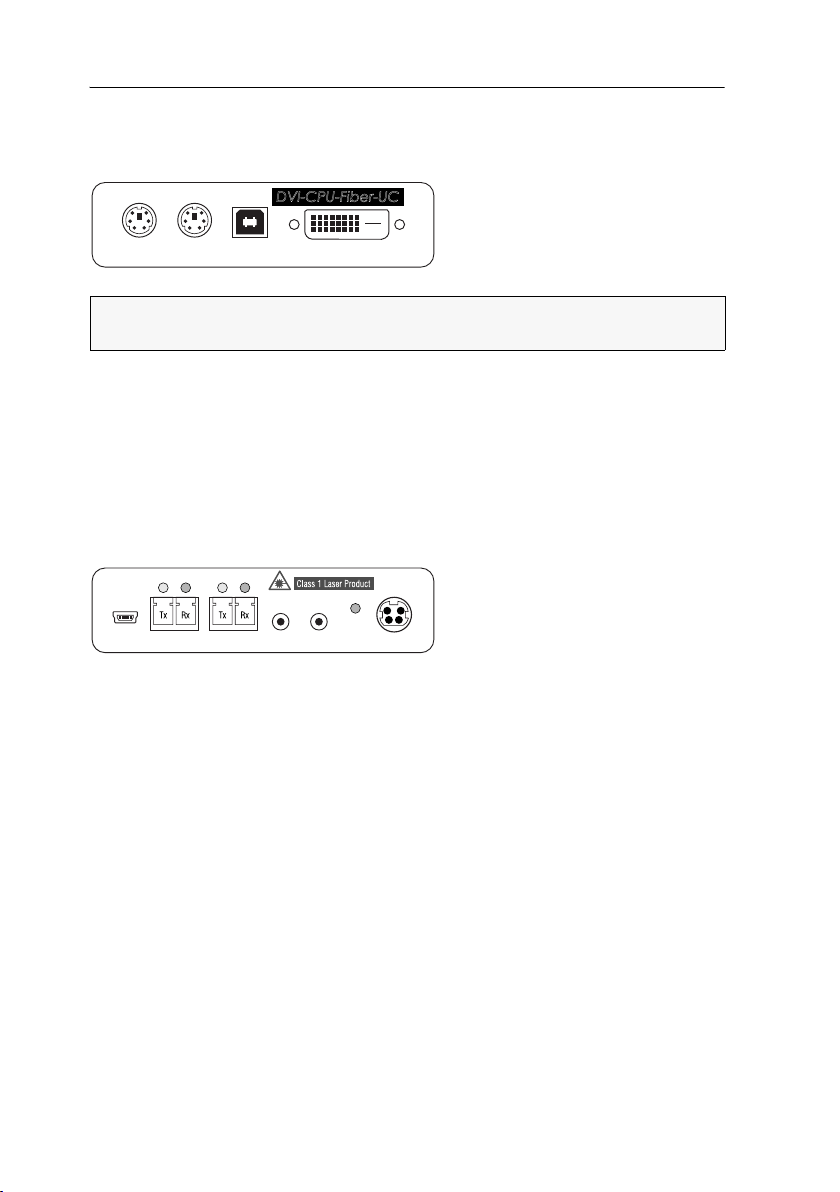
Target module »DVI-CPU-Fiber-UC«
MouseKey b.
USB K/M
DVI-D CPU
DVI-CPU-Fiber-UC
Link
Status
Trans. 2
Line In
Line Out
Power In
Service
Power
Trans. 1
Link
Status
Installation
Connecting the target computer
NOTE:
Keyboard and mouse signals can be transmitted to the computer using either
the PS/2 interfaces or the USB interface.
Keyb.: Use the purple plug of the Twin-PS/2 cable to connect the computer’s PS/2
keyboard interface to this interface.
Mouse: Use the green plug of the Twin-PS/2 cable to connect the computer’s PS/2
mouse interface to this interface.
USB K/M: Use the USB device cable to connect one of the computer’s USB interfaces
to this interface.
DVI-D CPU: Use the supplied video cable to connect the computer’s digital video out-
put to this interface.
Line In: Use one of the supplied audio cables to connect the computer’s Line Out
interface to this interface.
Line Out: Use one of the supplied audio cables to connect the computer’s Line In inter-
face to this interface.
28 · Target and user modules

Target module »DVI-CPU-Fiber-UC«
Connection to the matrix switch
The devices use components with laser technology which comply with laser
1.
class
They meet the requirements according to EN 60825-1:2007 and EN 60825-
2:2004+A1:2007 as well as U.S. CFR 1040.10 and 1040.11.
Mind the following instructions when dealing with laser beams:
Avoid eye contact with invisible laser beam on page 2
Always connect optical connections or cover them with protection caps on page 2
Only use G&D certified transmission modules on page 2
NOTE:
Use optical fibres with LC plugs to connect the devices. The cables are avail-
able as accessories.
IMPORTANT:
For each matrix switch, connect only one Trans. interface of the tar-
get module!
Trans. 1|Tx: Insert the LC plug of a compatible optical fibre cable.
Connect the other end of the cable to the Rx interface of a Dynamic Port provided at
the first matrix switch.
Trans. 1|Rx: Insert the LC plug of a compatible optical fibre cable.
Connect the other end of the cable to the Tx interface of the same Dynamic Port provided at the first matrix switch.
Trans. 2|Tx: Insert the LC plug of a compatible optical fibre cable.
Connect the other end of the cable to the Rx interface of a Dynamic Port provided at
the second matrix switch.
Trans. 2|Rx: Insert the LC plug of a compatible optical fibre cable.
Connect the other end of the cable to the Tx interface of the same Dynamic Port provided at the second matrix switch.
ADVICE:
You can also connect the target module directly to a compatible user mod-
ule.
Power supply
Power In: Connect the cable of the power pack to this interface. Now connect the
power cable to the power pack and a power socket.
Target and user modules · 29

Target module »DVI-CPU-Fiber-UC«
Status displays
The LED on the back panel of the target module shwos the status of the external
power pack:
LED Status Meaning
Power On The external power pack is connected and the required voltage (12 Volt)
Off The external power pack is not (properly) connected.
The blinking LEDS on the back panel highlight the following operating statuses of
the particular connection:
LED Status Meaning
Yellow Off No user module accesses the target module.
On A user module accesses the target module.
Blinking The incoming video signal was not detected.
Flashing No voltage at PS/2 interface or USB bus.
Green Off The target module is turned off.
Blinking The power pack is connected and supplies the required power.
Flashing The connection to the matrix switch is established.
On A user module accesses the target module.
Flickering Keyboard and mouse inputs are transmitted by the accessing user module.
is available.
The connection to the matrix switch could not be established.
No user module is accessing or the computer is turned off.
A computer is connected and turned on.
The flickering is defined by the user’s inputs.
30 · Target and user modules

Target module »DVI-CPU-Fiber-UC«
Technical data
DVI-CPU-FIBER-UC
Interfaces to computer
Date transmission to
matrix switches
Video Resolution @ 60 Hz: Max. 1920 × 1200 pixels
Audio Type: Bi-directional extension
Power supply Type: Portable power pack (12 V/2 A)
Housing Material: Anodised aluminium
Operational
environment
Conformity CE, RoHS
Video: 1 × DVI-D (single link)
Keyboard and mouse signals 2 × PS/2 socket
1 × USB-B
Audio: 2 × 3,5 mm jack plug
Interface: 2 × LC-Duplex socket
Transmission distance: DVI-CPU-Fiber-UC(M)
Max. 100 Meter (62,5μ/125μ),
Max. 200 Meter (50μ/125μ OM2)
Max. 400 Meter (50μ/125μ OM3)
DVI-CPU-Fiber-UC(S)
Max. 5.000 Meter (9μ/125μ OS1)
DVI-CPU-Fiber-UC(S+)
Max. 10.000 Meter (9μ/125μ OS1)
Colour depth: 24 bit
Pixel rate: 25 MHz to 165 MHz
Vertical frequency: 50 Hz to 180 Hz
Horizontal frequency: 30 kHz to 130 kHz
Standards: DVI 1.0, E-DDC
Resolution: 24 Bit
Refresh rate: 96 kHz
Bandwidth: 22 kHz
Connector: 1 × Mini-DIN 4 socket
Power input: Max. 600 mA @ 12 VDC
Dimensions (W × H × D): 105 × 26 × 104 mm
Weight: Approx. 360 g
Temperature: +5 to +45 °C
Air humidity: < 80%, non-condensing
Target and user modules · 31

Target module »DP-CPU«
Target module »DP-CPU«
With DP-CPU target modules, you can connect a computer with DisplayPort graphics
output to a digital matrix switch of the ControlCenter-Digital or the DVICenter series.
Users at the consoles of the matrix switch can access the target module and operate
the connected computer
Package contents
1 × Target module DP-CPU
1 × DisplayPort video cable (DP-Cable-M/M-2)
1 × USB device cable
1 × Twin PS/2 cable
2 × Audio cable
1 × Power pack (12V/2A)
1 × Power cable
Required accessories
1 × Category 5e (or better) twisted pair cable to connect the target module to
the matrix switch
32 · Target and user modules

Target module »DP-CPU«
MouseKeyb.
USB K/M
DP CPU
Installation
Connecting the target computer
NOTE:
Keyboard and mouse signals can be transmitted to the computer using either
the PS/2 interfaces or the USB interface.
Keyb.: Use the purple plug of the Twin-PS/2 cable to connect the computer’s PS/2
keyboard interface to this interface.
Mouse: Use the green plug of the Twin-PS/2 cable to connect the computer’s PS/2
mouse interface to this interface.
USB K/M: Use the USB device cable to connect one of the computer’s USB interfaces
to this interface.
DP CPU: Connect the computer’s Display Port digital video output to this interface.
Line In: Use one of the supplied audio cables to connect the computer’s Line Out
interface to this interface.
Line Out: Use one of the supplied audio cables to connect the computer’s Line In inter-
face to this interface.
Connection to the matrix switch
Trans.: Use a category 5e (or better) twisted pair cable to connect this interface to a
Dynamic
Port (RJ45) of a matrix switch.
ADVICE:
You can also connect the target module directly to a compatible user module.
Power supply
Power In: Insert the power pack’s connection cable to this interface.
Connect the power cable to the power pack and a power socket.
Target and user modules · 33

Target module »DP-CPU«
Status displays
The LED on the back panel of the target module shows the status of the external
power pack:
LED Status Meaning
Power On The external power pack is connected and the required voltage (12 Volt)
Off The external power pack is not (properly) connected.
The flashing Transmission LEDs highlight the following operating statuses of the
particular connection:
LED Status Meaning
Yellow Off No user module accesses the target module.
On A user module accesses the target module.
Blinking The incoming video signal was not detected.
Flashing No voltage at PS/2 interface or USB bus.
Green Off The target module is turned off.
Blinking The power pack is connected and supplies the required power.
Flashing The connection to the matrix switch is established.
On A user module accesses the target module.
Flickering Keyboard and mouse inputs are transmitted by the accessing user module.
is available.
The connection to the matrix switch could not be established.
No user module is accessing or the computer is turned off.
A computer is connected and turned on.
The flickering is defined by the user’s inputs.
34 · Target and user modules

Target module »DP-CPU«
Technical data
DP-CPU
Interfaces to computer
Date transmission to
the matrix switch
Video Resolution @ 60 Hz: Max. 1920 × 1200 pixels
Audio Type: Bi-directional extension
Power supply Type: Portable power pack (12 V/2 A)
Housing Material: Anodised aluminium
Operational
environment
Conformity CE, RoHS
Video: 1 × Display-Port
Keyboard and mouse signals 2 × PS/2 socket
1 × USB-B
Audio: 2 × 3,5 mm jack plug
Interface: 1 × RJ45 socket
Transmission distance: Max. 140 metres
Colour depth: 24 bit
Pixel rate: 25 MHz to 165 MHz
Vertical frequency: 50 Hz to 180 Hz
Horizontal frequency: 30 kHz to 130 kHz
Resolution: 24 Bit
Refresh rate: 96 kHz
Bandwidth: 22 kHz
Connector: 1 × Mini-DIN 4 socket
Power input: Max. 500 mA
Dimensions (W × H × D): 105 × 26 × 104 mm
Weight: Approx. 240 g
Temperature: +5 to +45 °C
Air humidity: < 80%, non-condensing
Target and user modules · 35

Target module »DP-CPU-UC«
Target module »DP-CPU-UC«
With DP-CPU-UC target modules, you can connect computers with DisplayPort graphics output to two different matrix switches of the ControlCenter-Digital or the DVICenter
series.
Users at consoles of both matrix switches can access the target module to operate the
connected computer.
NOTE:
The computer that is connected to the KVM matrix system via the target
module is called Target within the system.
Package contents
1 × Target module DP-CPU-UC
1 × DisplayPort video cable (DP-Cable-M/M-2)
1 × USB device cable
1 × Twin-PS/2 cable
2 × Audio cable
1 × Power pack (12V/2A)
1 × Power cable
Required accessories
2 × Category 5e (or better) twisted pair cables to connect the target module to
two matrix switches
36 · Target and user modules

Target module »DP-CPU-UC«
MouseKeyb.
USB K/M
DP CPU
Installation
Connecting the target computer
NOTE:
Keyboard and mouse signals can be transmitted to the computer using either
the PS/2 interfaces or the USB interface.
Keyb.: Use the purple plug of the Twin-PS/2 cable to connect the computer’s PS/2
keyboard interface to this interface.
Mouse: Use the green plug of the Twin-PS/2 cable to connect the computer’s PS/2
mouse interface to this interface.
USB K/M: Use the USB device cable to connect one of the computer’s USB interfaces
to this interface.
DP CPU: Connect the computer’s Display Port digital video output to this interface.
Line In: Use one of the supplied audio cables to connect the computer’s Line Out
interface to this interface.
Line Out: Use one of the supplied audio cables to connect the computer’s Line In inter-
face to this interface.
Connections to the matrix switches
IMPORTANT:
matrix switch!
NOTE:
Trans. 1: Connect this interface to a Dynamic Port (RJ45) of the first matrix switch.
Trans. 2: Connect this interface to a Dynamic Port (RJ45) of the second matrix switch.
ADVICE:
modules.
Connect only one of the target module’s Trans. interfaces for each
Use only category 5e (or better) twisted pair cables to connect the devices.
You can also connect the target module directly to up to two compatible user
Target and user modules · 37

Target module »DP-CPU-UC«
Power supply
Power In: Insert the power pack’s connection cable to this interface.
Connect the power cable to the power pack and a power socket.
Status displays
The LED on the back panel of the target module show the status of the external
power pack:
LED Status Meaning
Power On The external power pack is connected and the required voltage (12 Volt)
Off The external power pack is not (properly) connected.
The blinking Transmission LEDs highlight the following operating statuses of the
particular connection:
LED Status Meaning
Yellow Off No user module accesses the target module.
On A user module accesses the target module.
Blinking The incoming video signal was not detected.
Flashing No voltage at PS/2 interface or USB bus.
Green Off The target module is turned off.
Blinking The power pack is connected and supplies the required power.
Flashing The connection to the matrix switch is established.
On A user module accesses the target module.
Flickering Keyboard and mouse inputs are transmitted by the accessing user module.
is available.
The connection to the matrix switch could not be established.
No user module is accessing or the computer is turned off.
A computer is connected and turned on.
The flickering is defined by the user’s inputs.
38 · Target and user modules

Target module »DP-CPU-UC«
Technical data
DP-CPU-UC
Interfaces to computer
Data transmission to
matrix switches
Video Resolution @ 60 Hz: Max. 1920 × 1200 pixels
Audio Type: Bi-directional extension
Power supply Type: Portable power pack (12 V/2 A)
Housing Material: Anodised aluminium
Operational
environment
Conformity CE, RoHS
Video: 1 × Display-Port
Keyboard and mouse signals 2 × PS/2 socket
1 × USB-B
Audio: 2 × 3.5 mm jack plug
Interface: 2 × RJ45 socket
Transmission distance: Max. 140 metres
Colour depth: 24 bit
Pixel rate: 25 MHz to 165 MHz
Vertical frequency: 50 Hz to 180 Hz
Horizontal frequency: 30 kHz to 130 kHz
Resolution: 24 Bit
Refresh rate: 96 kHz
Bandwidth: 22 kHz
Connector: 1 × Mini-DIN 4 socket
Power input: Max. 600 mA
Dimensions (W × H × D): 105 × 26 × 104 mm
Weight: Approx. 260 g
Temperature: +5 to +45 °C
Air humidity: < 80%, non-condensing
Target and user modules · 39

Target module »VGA-CPU-UC«
Target module »VGA-CPU-UC«
With VGA-CPU-UC target modules, you can connect a computer with a VGA graphics
output to two different digital matrix switches of the ControlCenter-Digital or the DVI
Center series.
Users at the consoles of the matrix switch can access the target module to operate the
connected computer.
Package contents
1 × Target module VGA-CPU
1 × Video cable (VGA-M/M-2)
1 × USB device cable
1 × Twin-PS/2 cable
2 × Audio cable
1 × Power pack (12V/2A)
1 × Power cable
-
Required accessories
2 × Category 5e (or better) twisted pair cables to connect the target module to
two different matrix switches
40 · Target and user modules

Target module »VGA-CPU-UC«
MouseKey b.
USB K/M
VGA CPU
Power
Trans. 1
Trans. 2
Service
Line In
Line Out
Power In
Installation
Connecting the target computer
NOTE:
Keyboard and mouse signals can be transmitted to the computer using either
the PS/2 interfaces or the USB interface.
Keyb.: Use the purple plug of the Twin-PS/2 cable to connect the computer’s PS/2
keyboard interface to this interface.
Mouse: Use the green plug of the Twin-PS/2 cable to connect the computer’s PS/2
mouse interface to this interface.
USB K/M: Use the USB device cable to connect one of the computer’s USB interfaces
to this interface.
VGA CPU: Use the supplied video cables to connect the computer’s analogue video
output to this interface.
Line In: Use one of the supplied audio cables to connect the computer’s Line Out
interface to this interface.
Line Out: Use one of the supplied audio cables to connect the computer’s Line In inter-
face to this interface.
Connections to the matrix switches
IMPORTANT:
matrix switch!
NOTE:
Trans. 1: Connect this interface to a Dynamic Port (RJ45) of the first matrix switch.
Trans. 2: Connect this interface to a Dynamic Port (RJ45) of the second matrix switch.
ADVICE:
user modules.
Connect only one of the target module’s Trans. interfaces for each
Only use category 5e (or better) twisted pair cables to connect the devices.
You can also connect the target module directly to up to two compatible
Target and user modules · 41

Target module »VGA-CPU-UC«
Power supply
Power In: : Insert the power pack’s connection cable to this interface. Then, connect
the power cable to the power pack and a power socket.
Status displays
The LED on the back panel of the target module show the status of the external
power pack:
LED Status Meaning
Power On The external power pack is connected and the required voltage (12 Volt)
Off The external power pack is not (properly) connected.
The blinking Transmission LEDs highlight the following operating statuses of the
particular connection:
LED Status Meaning
Yellow Off No user module accesses the target module.
On A user module accesses the target module.
Blinking The incoming video signal was not detected.
Flashing No voltage at PS/2 interface or USB bus.
Green Off The target module is turned off.
Blinking The power pack is connected and supplies the required power.
Flashing The connection to the matrix switch is established.
On A user module accesses the target module.
Flickering Keyboard and mouse inputs are transmitted by the accessing user module.
is available.
The connection to the matrix switch could not be established.
No user module is accessing or the computer is turned off.
A computer is connected and turned on.
The flickering is defined by the user’s inputs.
42 · Target and user modules

Target module »VGA-CPU-UC«
Technical data
VGA-CPU-UC
Interfaces to computer
Data transmission to
matrix switches
Video Supported resolutions: 640 × 350 @ 60-120 Hz
Audio Type: Bi-directional extension
Power supply Type: Portable power pack (12 V/2 A)
Housing Material: Anodised aluminium
Operational
environment
Conformity CE, RoHS
Video: 1 × VGA
Keyboard and mouse signals 2 × PS/2 socket
1 × USB-B
Audio: 2 × 3.5 mm jack plug
Interface: 2 × RJ45 socket
Transmission distance: Max. 140 metres
640 × 400 @ 50-120 Hz
640 × 480 @ 50-120 Hz
720 × 400 @ 50-120 Hz
800 × 600 @ 50-120 Hz
1024 × 768 @ 50-120 Hz
1152 × 864 @ 50-85 Hz
1152 × 900 @ 50-76 Hz
1280 × 720 @ 50-85 Hz
1280 × 768 @ 50-100 Hz
1280 × 960 @ 50-75 Hz
1280 × 1024 @ 50-75 Hz
1360 × 768 @ 50-85 Hz
1400 × 1050 @ 50-75 Hz
1440 × 900 @ 50-85 Hz
1600 × 1200 @ 60 Hz
1680 × 1050 @ 60 Hz
1920 × 1080 @ 60 Hz
1920 × 1200 @ 60 Hz
Colour depth: 24 Bit
Pixel rate: 25 MHz bis 165 MHz
Norms: E-DDC
Resolution: 24 Bit
Refresh rate: 96 kHz
Bandwidth: 22 kHz
Connector: 1 × Mini-DIN 4 socket
Power input: Max. 600 mA @ 12 VDC
Dimensions (W × H × D): 105 × 26 × 104 mm
Weight: Approx. 250 g
Temperature: +5 to +45 °C
Air humidity: < 80%, non-condensing
Target and user modules · 43
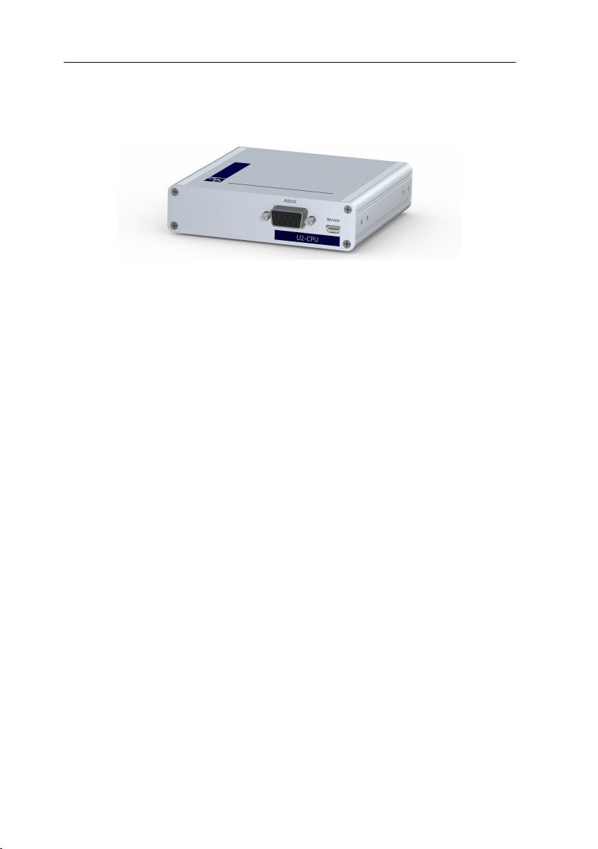
Target module »U2-R-CPU«
Target module »U2-R-CPU«
U2-CPU target modules receive USB and RS232 signals from U2-CON user modules and
transmit them to the computer.
Package contents
1 × Target module U2-R-CPU
1 × USB device cable
1 × RS232 cable
1 × Power pack (12V/2A)
1 × Power cable
Required accessory
1 × Category 5e (or better) twisted pair cable to connect the target module to
the matrix switch
44 · Target and user modules

Target module »U2-R-CPU«
Installation
Connecting the target computer
RS232: Use the RS232 cable to connect the computer’s 9-pin serial computer inter-
face to this interface (optional).
Trans.: Use a category 5e (or better) twisted pair cable to connect this interface to the
Dynamic
USB CPU: Use the USB device cable to connect one of the computer’s USB ports to this
port.
Power In: Insert the connection cable of the power pack to this interface. Now con-
nect the power cable to the power pack and a power outlet.
Port of the USB/RS232 Main Channel that is assigned to the target computer.
Status displays
The blinking Transmission LEDs show the following connection statuses:
LED Status Meaning
Yellow Off No connection to network.
On A user module is accessing the target module.
Green On A user module is accessing the target module.
Blinking No communication with matrix switch.
Flashing Connection to matrix switch established successfully.
No user module is accessing.
Target and user modules · 45

Target module »U2-R-CPU«
Technical data
U2-R-CPU
Interfaces to
target computer:
Data transmission to
matrix switch
USB 2.0 Transmission type: Transparent
RS232 Transmission type: Transparent
Power supply Type: Portable power pack
Housing Material: Anodised aluminium
Operational
environment
Conformity CE, RoHS
USB 2.0: 1 × USB-B
RS232: 1 × D-SUB 9 socket
Interface: 1 × RJ45 socket
Transmission length: Max. 140 metres
Transmission rate: Max. 480 Mbit/s
Transmission rate: Max. 115,200 bit/s
Signals: RxD, TxD, RTS, CTS, DTR, DSR, DCD
Connector: 1 × Mini-DIN 4 socket
Power consumption: 12 VDC/300 m A
Dimensions (W × H × D): 105 × 26 × 104 mm
Weight: Approx. 240 g
Temperature: + 5 to + 40°C
Air humidity: < 80%, non condensing
46 · Target and user modules

B
User modules
User module »DVI-CON«
With DVI-CON user modules, you can connect a console (DVI monitor, keyboard,
mouse and audio devices) to a digital matrix switch of the
DVICenter series
At the installed console, matrix switch users can access a target module to operate
the connected computer.
Package contents
1 × DVI-CON user module
1 × Power cable
.
ControlCenter-Digital or the
Required accessories
1 × Category 5e (or better) twisted pair cable to connect the user module to
the matrix switch
Target and user modules · 47

User module »DVI-CON«
Micro In
Keyb./Mouse
Main Power
Red. Power
DVI / VGA Out
LED out
Speaker
Mouse
Keyb.
Transmission
Generic
Installation
Connecting the console devices
NOTE:
Both keyboard and mouse signals can be transmitted to the computer using
the PS/2 or the USB interfaces.
Keyb.: Connect the PS/2 keyboard of the local console.
Mouse: Connect the PS/2 mouse of the local console.
Keyb./Mouse: Connect the USB keyboard and/or USB mouse of the local console.
NOTE:
You can also combine PS/2 and USB devices, for example by connecting a
USB mouse and a PS/2 keyboard.
Generic: By default (Keyb./Mouse mode), you can use this interface to connect another
USB input device or supported displays or tablets.
Enable the Generic HID mode (see page 106 f.) if you want to connect another USB
input device. In this mode, data of the USB input device remains unaltered when
transmitted to the active target module.
IMPORTANT:
with a keyboard connected to the
With enabled Generic HID mode, it is not possible to operate the OSD
Generic socket.
DVI/VGA Out: Connect the monitor of the local console.
Micro In: Connect the optional microphone of the local console.
Speaker: Connect the optional speakers of the local console.
48 · Target and user modules

User module »DVI-CON«
Connection to the matrix switch
Transmission: Use a category 5e (or better) twisted pair cable to connect the Transmis-
sion interface to a Dynamic Port (RJ45) of the matrix switch.
NOTE:
You can also connect the target module directly to a compatible user module.
Power supply
Main Power: Connect the power cable to the power pack and a power outlet.
Red. Power: If required, connect the power cable of the optional power pack to this
interface. This provides a redundant power supply. Connect the power cable with
the power pack and a power outlet of a different power circuit.
LED Out: If you expanded the functional range of the matrix switch by purchasing the
TradeSwitch function, connect the optional TS-LED-2 (order number A6100041) to this
interface.
Start-up
Start the user module by pressing the Main Power button of the power pack.
ADVICE:
the matrix switch.
The active hotkey configuration is displayed during the System Startup of
Target and user modules · 49

User module »DVI-CON«
Trans.
System
Status
Main
Red.
Power
Console
Video
K/M
Service
Status displays
Front panel
The LEDs on the front panel of the user module show the system’s operating status.
Section LED Status Meaning
Power Red. On The optional power pack is connected and the required voltage
Off The optional power pack is not (properly) connected.
Main On The power pack provides the required voltage.
Off The power button is turned off or the connection with the mains
Status Trans. On The communication with the matrix switch could be established.
Off The communication with the matrix switch could not be estab-
System On The device is booting or carries out a firmware update.
Blinking
Console Video On Stable image signal at video input.
Off The incoming video signal could not be detected or it lacks the
K/M On A local keyboard was found.
Off No power at PS/2 interface or USB bus.
Blinking
Volt) is available.
(12
could not be established.
Check the proper connection of the power supply cable.
lished.
The system is ready for operation.
required quality to be processed by the system.
The CPU input (PS/2 or USB) is active and ready.
No local keyboard was found.
50 · Target and user modules

User module »DVI-CON«
Micro In
Keyb./Mouse
Main Power
Red. Power
DVI / VGA Out
LED out
Speaker
Mouse
Keyb.
Transmission
Generic
Back panel
The Transmission interface at the back panel of the user module provides additional
status LEDs. The LEDs have the following meaning:
LED Colour Status Meaning
Left Yellow Off No connection to network.
Blinking Network connection to an end device.
Right Green On A user module is accessing the target module.
Blinking No communication with matrix switch.
Flashing Connection to matrix switch established.
Flickering Keyboard and mouse inputs are forwarded by the accessing
Yellow Flashing A firmware update is carried out.
No user module is accessing.
user module.
The flickering is defined by the user’s entries.
TradeSwitch-LED
The optional TS-LED (order number A6100041) lights if the keyboard and mouse signals of a master console are accessing the user
module.
NOTE:
Keyboard and mouse signals can only access another user module or a tar-
get computer if you activated the TradeSwitch function for the matrix switch.
Target and user modules · 51

User module »DVI-CON«
Technical data
DVI-CON
Interfaces to
console:
Data transmission to
matrix switch
Video Resolution @ 60 Hz: Max. 1920 × 1200 pixels
Audio Type: Bi-directional extension
Main power supply Type: Internal power pack
Redundant
power supply
Casing Material: Anodised aluminium
Operational
environment
Conformity CE, RoHS
Video: 1 × DVI-I (DVI Single-Link or VGA)
Keyboard and mouse signals: 2 × PS/2 socket
2 × USB-A
Audio: 2 × 3.5 mm jack socket
Tradeswitch-LED: 1 × D-SUB 9 socket
Interface: 1 × RJ45 socket
Transmission length: Max. 140 meters
Resolution @ 85 Hz: Max. 1280 × 1024 pixels
Colour depth: 24 bits
Pixel rate: 25 MHz to 165 MHz
Vertical frequency: 50 Hz to 180 Hz
Horizontal frequency: 30 kHz to 130 kHz
Resolution: 24 Bit
Sampling rate: 96 kHz
Bandwidth: 22 kHz
Connection: 1 × IEC plug(IEC-320 C14)
Current consumption: 100 - 240 VAC; 0.3 A - 0.2 A
Type: External power pack (12 V/2 A)
Connection: 1 × Mini-DIN 4 socket(Power In)
Current consumption: 12 VDC; 1.2 A
Dimensions (W × H × D): 210 × 44 × 210 mm
Weight: Approx. 1.3 kg
Temperature: +5 to +45 °C
Air humidity: < 80%, non-condensing
52 · Target and user modules

User module »DVI-CON-MC2«
User module »DVI-CON-MC2«
With DVI-CON-MC2 user modules, you can connect a dual-monitor console (two DVI
monitors, keyboard, mouse and audio devices) to a digital matrix switch of the Con-
trolCenter-Digital or the DVICenter series.
At the installed console, matrix switch users can access a target module to operate
the connected computer.
When using the console to access a target module DVI-CPU-MC2 connected to a dualhead computer, the monitors display the separate images of the graphics outputs.
When accessing a target module with one graphics input only, only the first monitor
displays an image.
ADVICE:
puter by using two separate target modules DVI-CPU.
In this case, add both target modules in the web application to channel group.
Instead of an MC2 target module, you can also connect a dual-head com-
Package contents
1 × User module DVI-CON-MC2
1 × Power cable
Required accessories
2 × Category 5e (or better) twisted pair cables to connect the user module to a
KVM matrix switch of the
ControlCenter-Digital or the DVICenter series
Target and user modules · 53

User module »DVI-CON-MC2«
Transmission 1
Micro In Red. Power
DVI / VGA Out 1
LED out
Speaker
Mouse
Keyb.
Transmission 2
DVI / VGA Out 2
Installation
Connecting console devices
DVI/VGA Out 1: Connect the first console monitor.
DVI/VGA Out 2: Connect the second console monitor.
Micro In: Connect the console microphone (optional).
Speaker: Connect the console speakers (optional).
NOTE:
Console keyboard and console mouse can be connected to the user module’s
USB or PS/2 interfaces.
Keyb.: Connect the console’s PS/2 keyboard.
Mouse: Connect the console’s PS/2 mouse.
Keyb./Mouse: Connect the console’s USB keyboard and/or USB mouse.
Generic: By default (Keyb./Mouse mode), you can use this interface to connect another
USB input device or supported displays or tablets.
Enable the Generic HID mode (see page 106 f.) if you want to connect another USB
input device. In this mode, data of the USB input device remains unaltered when
transmitted to the active target module.
IMPORTANT:
with a keyboard connected to the
With enabled Generic HID mode, it is not possible to operate the OSD
Generic socket.
LED Out: If you purchased and added the TradeSwitch feature to the matrix switch,
connect the optional
TS-LED2 here (order number A6100041).
54 · Target and user modules

User module »DVI-CON-MC2«
Keyb./Mouse
Generic
Transmission 1
Micro In Red. Power
DVI / VGA Out 1
LED out
Speaker
Mouse
Keyb.
Transmission 2
DVI / VGA Out 2
Connection to the matrix switch
NOTE:
Use category 5e (or better) twisted pair cables to connect the devices.
Transmission 1: Connect this interface to a Dynamic Port (RJ45) of the matrix switch.
Transmission 2: Connect this interface to another Dynamic Port (RJ45) of the matrix
switch.
NOTE:
You can also connect the target module directly to a compatible target module.
Power supply
Main Power: Connect the supplied power cable.
Insert the cable’s Schuko plug in a power socket.
Red. Power: Connect the connection cable of a compatible power pack to provide the
user module with a second, redundant power supply.
Startup
Turn on the user module after its installation.
Use the Main Power power pack or a redundant power pack to establish the power
supply:
Turn on the Main Power power pack.
Use an optional power pack to supply the Red. Power socket with power.
Target and user modules · 55

User module »DVI-CON-MC2«
Automatic channel grouping
When operating the user module for the first time, the matrix switch recognises the
main channel and the user module’s additional channel. The channels are automati
cally added to a channel group.
The web application uses the following icons to mark the different types of channels:
Main channel: computer and user superimposed by the digit 2
Video channel: multiple monitors in a row
NOTE:
In addition to the data of the KVM main channel, a channel group transmits
up to seven additional video channels and/or one USB 2.0 or RS
In the web application, the list of user modules lists grouped modules separately.
icon next to the module name shows that the module is part of a channel
The
group.
Click the icon to get information about the channel group.
NOTE:
You can adjust adjsut any channel groups that were created automatically
or manually. More information about channel groups is given in the separate
manuals of the matrix switch web applications.
232 channel.
-
56 · Target and user modules

User module »DVI-CON-MC2«
Status displays
Front panel
Section LED Status Meaning
Power Red. On The optional power pack is connected and supplies 12 Volt.
Off The optional power pack is not (properly) connected.
Main On The power pack is turned on and supplies the required
Off The power pack is turned off or the connection to the mains
Status Trans. 1 On The communication to the matrix switch is established suc-
Off The communication to the matrix switch could not be
System On Device boots or firmware update is executed.
Flashing System is ready for operation.
Console Video 1 On Strong video signal at first video input.
Off No signal at first video input, or the signal quality is too
K/M On A local keyboard was detected.
Off No power at PS/2 interface or USB bus.
Flashing The CPU input (PS/2 or USB) is active and ready.
MC2 Video 2 On Strong video signal at second video input.
Off No signal at second video input, or the signal quality is too
Trans. 2 On The communication to the matrix switch is established suc-
Off The communication to the matrix switch could not be
voltage.
could not be established.
cessfully.
established.
weak to be processed by the system.
A local keyboard was not detected.
weak to be processed by the system.
cessfully.
established.
Target and user modules · 57

User module »DVI-CON-MC2«
Keyb./Mouse
Generic
Transmission 1
Micro In Red. Power
DVI / VGA Out 1
LED out
Speaker
Mouse
Keyb.
Transmission 2
DVI / VGA Out 2
Back panel
The Transmission interfaces at the user module’s back panel provide additional status
LEDs.
Interface LED Status Meaning
Transmission 1 Yellow Off No data connection to matrix switch.
Flashing Data connection to matrix switch established.
Green Off No user is logged in at the user module.
On A user is logged in at the user module.
Transmission 2 Yellow Off No data connection to matrix switch.
On Data connection to matrix switch established.
Green Off No user is logged in at the user module.
On A user is logged in at the user module.
TradeSwitch-LED
The optionally available TS-LED (item number A6100041) flashes
when keyboard and mouse signals of a master console are switched
to the user module.
NOTE:
Keyboard and mouse signals can only be switched to another user module
or target computer if you purchased the TradeSwitch function for the
58 · Target and user modules
matrix switch.

User module »DVI-CON-MC2«
Technical data
DVI-CON-MC2
Interfaces to console Video: 2 × DVI-I (DVI single-link or VGA)
Keyboard and mouse signals 2 × PS/2 socket
Audio: 2 × 3.5 mm jack plug
Tradeswitch-LED: 1 × D-SUB 9 socket
Data transmission to
matrix switch
Video Resolution @ 60 Hz: Max. 1920 × 1200 pixels
Audio Type: Bi-directional extension
Main power supply Type: Internal power pack
Redundant
power supply
Housing Material: Anodised aluminium
Operational
environment
Conformity CE, RoHS
Interfaces: 2 × RJ45 socket
Transmission distance: Max. 140 metres
Resolution @ 85 Hz: Max. 1280 × 1024 pixels
Colour depth: 24 Bit
Video bandwidth: 25 MHz to 165 MHz
Vertical frequency: 50 Hz to 180 Hz
Horizontal frequency: 30 kHz to 130 kHz
Resolution: 24 bits
Refresh rate: 96 kHz
Bandwidth: 22 kHz
Connector: 1 × IEC plug (IEC-320 C14)
Power input: 100 - 240 VAC; 0.3 A - 0.2 A
Type: External power pack
Connector: 1 × Mini-DIN 4 socket
Power input: 12 VDC; 1.3A
Dimensions (W × H × D): 435 × 44 × 210 mm
Weight: Approx. 3.0 kg
Temperature: +5 to +45 °C
Air humidity: < 80%, non condensing
2 × USB-A
Target and user modules · 59

User module »DVI-CON-MC4«
User module »DVI-CON-MC4«
With DVI-CON-MC4 user modules, you can connect a dual-monitor console (four DVI
monitors, keyboard, mouse and audio devices) to a digital matrix switch of the Con-
trolCenter-Digital or the DVICenter series.
At the installed console, matrix switch users can access a target module to operate
the connected computer.
When using the console to access a multi-monitor computer with four graphics outputs, the separate images of the graphics outputs are displayed on the console monitors.
NOTE:
Connecting a multi-monitor computer with four video outputs requires four
target modules of the
In the web application, you can add the target modules of the multi-monitor computers to a channel groups More information about this topic is given in the chapter Expanding the system through port grouping of the web application manual.
When accessing the system with a target module with only one graphics input, only
the first monitor shows an image.
DVI-CPU series or two target modules of the DVI-CPU-MC2 series.
Package contents
1 × User module DVI-CON-MC4
1 × Power cable
Required accessories
4 × Category 5e (or better) twisted pair cables to connect the user module to
the matrix switch
60 · Target and user modules

User module »DVI-CON-MC4«
Transmission 1
Micro In Red. Power
DVI / VGA Out 1
LED out
Speaker
Mouse
Keyb.
Transmission 2
DVI / VGA Out 2
Transmission 3
Installation
Connecting the console devices
DVI/VGA Out 1: Connect the first console monitor.
DVI/VGA Out 2: Connect the second console monitor.
Micro In: Connect the console microphone (optional).
Speaker: Connect the console speakers (optional).
NOTE:
Console keyboard and console mouse can be connected to the user module’s
USB or PS/2 interfaces.
Keyb.: Connect the console PS/2 keyboard.
Mouse: Connect the console PS/2 mouse.
Keyb./Mouse: Connect the console USB keyboard and/or USB mouse.
Generic: By default (Keyb./Mouse mode), you can use this interface to connect another
USB input device or supported displays or tablets.
Enable the Generic HID mode (see page 106 f.) if you want to connect another USB
input device. In this mode, data of the USB input device remains unaltered when
transmitted to the active target module.
IMPORTANT:
with a keyboard connected to the
With enabled Generic HID mode, it is not possible to operate the OSD
Generic socket.
LED Out: If you purchased and added the TradeSwitch feature to the matrix switch, con-
nect the optional TS-LED2 here (order number A6100041).
DVI/VGA Out 3: Connect the third console monitor.
DVI/VGA Out 4: Connect the fourth console monitor.
Target and user modules · 61

User module »DVI-CON-MC4«
Keyb./Mouse
Generic
Transmission 3
Transmission 1
Micro In Red. Power
DVI / VGA Out 1
LED out
Speaker
Mouse
Keyb.
Transmission 2
DVI / VGA Out 2
Connection to the matrix switch
NOTE:
Use category 5e (or better) twisted pair cables to connect the devices.
ADVICE:
You can also connect the target module directly to a compatible target mod-
ule.
Transmission 1: Connect this interface to a Dynamic Port (RJ45) of the matrix switch.
Transmission 2: Connect this interface to another Dynamic Port (RJ45) of the matrix
switch.
NOTE:
Use category 5e (or better) twisted pair cables to connect the devices..
Transmission 3: Connect this interface to another Dynamic Port (RJ45) of the matrix
switch.
Transmission 4: Connect this interface to another Dynamic Port (RJ45) of the matrix
switch.
Power supply
Main Power: Connect the supplied power cable.
Insert the cable’s Schuko plug in a power socket.
Red. Power: Connect the connection cable of a compatible power pack to provide the
user module with a second, redundant power supply.
62 · Target and user modules

User module »DVI-CON-MC4«
Startup
Turn on the user module after its installation.
Use the Main Power power pack or a redundant power pack to establish the power
supply:
Turn on the Main Power power pack.
Use an optional power pack to supply the Red. Power socket with power.
Automatic channel grouping
When operating the user module for the first time, the matrix switch recognises the
main channel and the user module’s additional channel. The channels are automati
cally added to a channel group.
The web application uses the following icons to mark the different types of channels:
Main channel: computer and user superimposed by the digit 2
Video channel: multiple monitors in a row
NOTE:
In addition to the data of the KVM main channel, a channel group transmits
up to seven additional video channels and/or one USB 2.0 or RS
In the web application, the list of user modules lists grouped modules separately.
The
icon next to the module name shows that the module is part of a channel
group.
Click the icon to get information about the channel group.
232 channel.
-
NOTE:
You can adjust adjsut any channel groups that were created automatically
or manually. More information about channel groups is given in the separate
manuals of the matrix switch web applications.
Target and user modules · 63

User module »DVI-CON-MC4«
Status displays
Front panel
Section LED Status Meaning
Power Red. On The optional power pack is connected and supplies 12 Volt.
Off The optional power pack is not (properly) connected.
Main On The power pack is turned on and supplies the required
Off The power pack is turned off or the connection to the mains
Status Trans. 1 On The communication to the matrix switch is established success-
Off The communication to the matrix switch could not be estab-
System On Device boots or firmware update is executed.
Flashing
Console Video 1 On Strong video signal at first video input.
Off No signal at first video input, or the signal quality is too weak to
K/M On A local keyboard was detected.
Off No power at PS/2 interface or USB bus.
Flashing
MC2 Video 2 On Strong video signal at second video input.
Off No signal at second video input, or the signal quality is too
Trans. 2 On The communication to the matrix switch is established success-
Off The communication to the matrix switch could not be estab-
voltage.
could not be established.
fully.
lished.
System is ready for operation.
be processed by the system.
The CPU input (PS/2 or USB) is active and ready.
A local keyboard was not detected.
weak to be processed by the system.
fully.
lished.
64 · Target and user modules

User module »DVI-CON-MC4«
Keyb./Mouse
Generic
Transmission 3
Transmission 1
Micro In Red. Power
DVI / VGA Out 1
LED out
Speaker
Mouse
Keyb.
Transmission 2
DVI / VGA Out 2
MC3 Video 3 On Strong video signal atthird video input.
Off No signal at third video input, or the signal quality is too weak
to be processed by the system.
Trans. 3 On The communication to the matrix switch is established success-
fully.
Off The communication to the matrix switch could not be estab-
lished.
MC4 Video 4 On Strong video signal at fourth video input.
Off No signal at fourth video input, or the signal quality is too weak
to be processed by the system.
Trans. 4 On The communication to the matrix switch is established success-
fully.
Off The communication to the matrix switch could not be estab-
lished.
Back panel
The Transmission interfaces at the user module’s back panel provide additional status
LEDs.
Interface LED Status Meaning
Transmission 1 Yellow Off No data connection to matrix switch.
Blinking Data connection to matrix switch established.
Green Off No user is logged in at the user module.
On A user is logged in at the user module.
Transmission 2 Yellow Off No data connection to matrix switch.
On Data connection to matrix switch established.
Green Off No user is logged in at the user module.
On A user is logged in at the user module.
Target and user modules · 65

User module »DVI-CON-MC4«
Interface LED Status Meaning
Transmission 3 Yellow Off No data connection to matrix switch.
Blink-
Data connection to matrix switch established.
ing
Green Off No user is logged in at the user module.
On A user is logged in at the user module.
Transmission 4 Yellow Off No data connection to matrix switch.
On Data connection to matrix switch established.
Green Off No user is logged in at the user module.
On A user is logged in at the user module.
TradeSwitch-LED
The optionally available TS-LED (item number A6100041) flashes
when keyboard and mouse signals of a master console are switched
to the user module.
NOTE:
Keyboard and mouse signals can only be switched to another user module
or target computer if you purchased the TradeSwitch function for the
matrix switch.
66 · Target and user modules

User module »DVI-CON-MC4«
Technical data
DVI-CON-MC4
Interfaces to console Video: 4 × DVI-I (DVI Single-Link or VGA)
Keyboard and mouse signals 2 × PS/2 socket
Audio: 2 × 3.5 mm jack plug
Tradeswitch-LED: 1 × D-SUB 9 socket
Data transmission to
matrix switch
Video Resolution @ 60 Hz: Max. 1920 × 1200 pixels
Audio Type: Bi-directional extension
Main power supply Type: Internal power pack
Redundant
power supply
Housing Material: Anodised aluminium
Operational
environment
Conformity CE, RoHS
Interfaces: 4 × RJ45 socket
Transmission distance: Max. 140 metres
Resolution @ 85 Hz: Max. 1280 × 1024 pixels
Colour depth: 24 Bit
Video bandwidth: 25 MHz to 165 MHz
Vertical frequency: 50 Hz to 180 Hz
Horizontal frequency: 30 kHz to 130 kHz
Resolution: 24 bits
Refresh rate: 96 kHz
Bandwidth: 22 kHz
Connector: 1 × IEC plug (IEC-320 C14)
Power input: 100 - 240 VAC; 0.5 A - 0.3 A
Type: External power pack
Connector: 1 × Mini-DIN 4-Buchse
Power input: 12 VDC; 2.0A
Dimensions (W × H × D): 435 × 44 × 210 mm
Weight: Approx. 3.0 kg
Temperature: +5 to +45 °C
Air humidity: < 80%, non condensing
2 × USB-A
Target and user modules · 67

User module »DVI-CON-Fiber«
User module »DVI-CON-Fiber«
With DVI-CON-Fibre user modules, you can use optical fibres to connect a console (DVI
monitor, keyboard, mouse and audio devices) to the matrix switch ControlCenter-Dig-
ital
NOTE:
The user modules con be connected only to an I/O card of the
CCD-I/O 16-Card-Fiber series.
Both, the user module and the I/O card are available as single-mode variants or as
multi-mode variants.
Make sure that the port at the user module, the Dynamic-Port at the IO card and the
optical fibres are compatible with each other.
At the installed console, matrix switch users can access a target module to operate
the connected computer.
Package contents
1 × User module DVI-CON-Fiber
1 × Power cable
Required accessories
1 × Compatible optical fibre cable to connect the user module to
the matrix switch
68 · Target and user modules

User module »DVI-CON-Fiber«
Link
Status
Transmission
Main Power
Red. Power
DVI / VGA Out
LED out
Mouse
Keyb.Micro In
Keyb./MouseSpeaker
Generic
Installation
Connecting the console devices
Abbildung 1: Rückansicht des Arbeitsplatzmoduls
NOTE:
Both keyboard and mouse signals can be transmitted to the computer using
the PS/2 or the USB interfaces.
Keyb.: Connect the PS/2 keyboard of the local console.
Mouse: Connect the PS/2 mouse of the local console.
Keyb./Mouse: Connect the USB keyboard and/or USB mouse of the local console.
NOTE:
You can also use PS/2 and USB devices, for example by connecting a USB
mouse and a PS/2 keyboard.
Generic: By default (Keyb./Mouse mode), you can use this interface to connect another
USB input device or supported displays or tablets.
Enable the Generic HID mode (see page 106 f.) if you want to connect another USB
input device. In this mode, data of the USB input device remains unaltered when
transmitted to the active target module.
IMPORTANT:
with a keyboard connected to the
With enabled Generic HID mode, it is not possible to operate the OSD
Generic socket.
DVI/VGA Out: Connect the monitor of the local console.
Micro In: Connect the microphone of the local console (optional).
Speaker: Connect the speakers of the local console (optional).
LED Out: If you purchased and added the TradeSwitch feature to the matrix switch, con-
nect the optional TS-LED2 here (order number A6100041).
Target and user modules · 69

User module »DVI-CON-Fiber«
Connection to the matrix switch
The devices use components with laser technology which comply with laser
1.
class
They meet the requirements according to EN 60825-1:2007 and EN 60825-
2:2004+A1:2007 as well as U.S. CFR 1040.10 and 1040.11.
Mind the following instructions when dealing with laser beams:
Avoid eye contact with invisible laser beam on page 2
Always connect optical connections or cover them with protection caps on page 2
Only use G&D certified transmission modules on page 2
NOTE:
Use optical fibres with LC plugs to connect the devices. The cables are avail-
able as accessories.
Transmission |Tx: Insert the LC plug of an optical fibre cable.
Connect the other end of the cable to the Rx interface of a compatible Dynamic Port
provided at the matrix switch.
Transmission|Rx: Insert the LC plug of an optical fibre cable.
Connect the other end of the cable to the Tx interface of the same Dynamic Ports provided at the matrix switch.
ADVICE:
ule.
You can also connect the target module directly to a compatible user mod-
Power supply
Main Power: Connect the power cable with the power pack and a power socket.
Red. Power: Connect the cable of the optional power pack to establish a redundant
power supply. Connect the power cable with the power pack and a power socket of
another power circuit.
Start-up
Turn on the power button of the Main Power power pack.
ADVICE:
ration of the matrix switch is shown.
70 · Target and user modules
During the System Startup of the suer module. the current hotkey configu-

User module »DVI-CON-Fiber«
Trans.
System
Status
Main
Red.
Power
Video
K/M
Service
Console
Status displays
Front panel
The LEDs on the front panel of the user modules show the system’s operating status.
Section LED Status Meaning
Power Red. On The optional power pack is connected and supplies 12 Volt.
Off The optional power pack is not (properly) connected.
Main On The power pack provides the required voltage.
Off The power pack is turned off or the connection to the mains could
Status Trans. On The communication to the matrix switch is established success-
Off The communication to the matrix switch could not be established.
System On Device boots or firmware update is executed.
Blinking
Console Video 1 On Strong video signal at first video input.
Off No signal at first video input, or the signal quality is too weak to
K/M On A local keyboard was detected.
Off No power at PS/2 interface or USB bus.
Flashing
not be established.
Check the proper connection of the power cable at the main power
pack.
fully.
System is ready for operation.
be processed by the system.
The CPU input (PS/2 or USB) is active and ready.
A local keyboard was not detected.
Target and user modules · 71

User module »DVI-CON-Fiber«
Link
Status
Transmission
Main Power
Red. Power
DVI / VGA Out
LED out
Mouse
Keyb.Micro In
Keyb./MouseSpeaker
Generic
Back panel
The back panel of the user module provides additional status LEDS. They have the
following meaning:
LED Colour Status Meaning
Link Yellow Off No connection to network.
Blinking Network connection to end device established.
Status Green On A user module is accessing the target module.
Blinking Communication to matrix switch not possible.
Flashing Connection to matrix switch successfully established.
Flickering Keyboard and mouse inputs are transmitted by the accessing
Yellow Flashing Firmware is updated.
No accessing target module.
user module.
The flickering is defined by the user’s inputs.
TradeSwitch-LED
The optionally available TS-LED (item number A6100041) flashes
when keyboard and mouse signals of a master console are switched
to the user module.
NOTE:
Keyboard and mouse signals can only be switched to another user module
or target computer if you purchased the TradeSwitch ffeature for the
72 · Target and user modules
matrix switch.

User module »DVI-CON-Fiber«
Technical data
DVI-CON-FIBER
Interfaces to console Video: 1 × DVI-I (DVI Single-Link or VGA)
Keyboard and mouse signals 2 × PS/2 socket
Audio: 2 × 3.5 mm jack plug
Tradeswitch-LED: 1 × D-SUB 9 socket
Data transmission to
matrix switch
Video Resolution @ 60 Hz: Max. 1920 × 1200 pixels
Audio Type: Bi-directional extension
Main power supply Type: Internal power pack
Redundant
power supply
Housing Material: Anodised aluminium
Operational
environment
Conformity CE, RoHS
Interfaces: 1 × LC-Duplex socket
Transmission distance: DVI-CON-Fiber(M)
Resolution @ 85 Hz: Max. 1280 × 1024 pixels
Colour depth: 24 Bit
Video bandwidth: 25 MHz to 165 MHz
Vertical frequency: 50 Hz to 180 Hz
Horizontal frequency: 30 kHz to 130 kHz
Resolution: 24 bits
Refresh rate: 96 kHz
Bandwidth: 22 kHz
Connector: 1 × IEC plug (IEC-320 C14)
Power input: 100 - 240 VAC; 0.3 A - 0.2 A
Type: Portable power pack (12 V/2 A)
Connector: 1 × Mini-DIN 4 socket (Power In)
Power input: 12 VDC; 1.1 A
Dimensions (W × H × D): 210 × 44 × 210 mm
Weight: Approx. 1.3 kg
Temperature: +5 to +45 °C
Air humidity: < 80%, non condensing
3 × USB-A
Max. 100 Meter (62,5μ/125μ),
Max. 200 Meter (50μ/125μ OM2)
Max. 400 Meter (50μ/125μ OM3)
DVI-CON-Fiber(S)
Max. 5.000 Meter (9μ/125μ OS1)
DVI-CON-Fiber(S+)
Max. 10.000 Meter (9μ/125μ OS1)
Target and user modules · 73

User module »DVI-CON-2«
User module »DVI-CON-2«
With DVI-CON user modules, you can connect a console (DVI monitor, keyboard,
mouse and audio devices) to two digital matrix switches of the
or the DVICenter series
At the installed console, matrix switch users can access a target module to operate
the connected computer.
The buttons on the front panel of the user module or configured key combinations
(select keys) let users switch between the connected matrix switches.
.
ControlCenter-Digital
ADVICE:
to each of the two channels.
Instead of a matrix switch, you can also connect a compatible target module
Package contents
1 × DVI-CON-2 user module
1 × Power cable
Required accessories
2 × Category 5e (or better) twisted pair cables to connect the user module to two
the matrix switches
74 · Target and user modules

User module »DVI-CON-2«
Micro In
Keyb./Mouse
Main Power
Red. Power
DVI / VGA Out
LED out
Speaker
Mouse
Keyb.
Transmission 1
Transmission 2
Generic
Installation
Connecting the console devices
DVI/VGA Out: Connect the monitor/projector of the local console.
Micro In: Connect the optional microphone of the local console.
Speaker: Connect the optional speakers of the local console.
HINWEIS:
Console keyboard and console mouse can be connected to the user mod-
ule’s USB or PS/2 interfaces.
Keyb.: Connect the PS/2 keyboard of the local console.
Mouse: Connect the PS/2 mouse of the local console.
Keyb./Mouse: Connect the USB keyboard and/or the USB mouse of the local
console.
NOTE:
Mixed operation, for example connecting a USB mouse and a PS/2 key-
board is supported, too.
Generic: By default (Keyb./Mouse mode), you can use this interface to connect another
USB input device or supported displays or tablets.
Enable the Generic HID mode (see page 106 f.) if you want to connect another USB
input device. In this mode, data of the USB input device remains unaltered when
transmitted to the active target module.
IMPORTANT:
with a keyboard connected to the
With enabled Generic HID mode, it is not possible to operate the OSD
Generic socket.
LED Out: If you purchased and added the TradeSwitch feature to the matrix switch, con-
nect the optional TS-LED2 here (order number A6100041).
Target and user modules · 75

User module »DVI-CON-2«
Connection to the matrix switch
NOTE:
Use category 5e (or better) twisted pair cables to connect the devices.
Transmission 1: Connect this interface to a Dynamic Port (RJ45) of the matrix switch.
Transmission 2: Connect this interface to another Dynamic Port (RJ45) of the matrix
switch.
ADVICE:
module.
You can also connect the Transmission interface directly to a compatible target
Power supply
Main Power: Connect the power cable to the power pack and a power outlet.
Red. Power: If required, connect the power cable of the optional power pack to this
interface. This provides a redundant power supply. Connect the power cable with
the power pack and a power outlet of a different power circuit.
Start-up
Start the user module by pressing the Main Power button of the power pack.
ADVICE:
the matrix switch.
The active hotkey configuration is displayed during the System Startup of
Switching
The buttons on the front panel of the user module or configured key combinations
(select keys) let users switch between the connected matrix switches.
How to switch channels via buttons:
Press the button of the desired channel to activate it.
How to switch channels via key combinations:
On the console keyboard, press Hotkey+Select key.
In the default settings, the select keys are Alt+1 (channel 1) and Alt+2 (channel 2).
76 · Target and user modules

User module »DVI-CON-2«
Trans.
System
Main
Red.
Video
K/M
Status
Power
Service
Console
Status
Active
Trans. 1
Trans. 2
Status displays
Front panel
The LEDs on the front panel of the user module show the system’s operating status.
Section LED Status Meaning
Power Red. On The optional power pack is connected and the required voltage
Off The optional power pack is not (properly) connected.
Main On The main power supply provides the required voltage.
Off The power button is turned off or the connection with the mains
Status Trans. On The communication with the connected matrix switch or the tar-
Off The communication with a matrix switch or target module of the
System On The device is booting or carries out a firmware update.
Blinking The system is ready for operation.
Console Video On Stable image signal at video input.
Off The incoming video signal could not be detected or it lacks the
K/M On A local keyboard was found.
Off No power at PS/2 interface or USB bus.
Blinking The CPU input (PS/2 or USB) is active and ready.
Trans. Active On Active channel.
Off Inactive channel.
Status On The communication with the connected matrix switch or the tar-
Off The communication with a matrix switch or target module of this
Volt) is available.
(12
could not be established.
Check the proper connection of the power supply cable.
get module of the active channel could be established successfully.
active channel could not be established.
required quality to be processed by the system.
No local keyboard was found.
get module of this channel was established successfully.
active channel could not be established.
Target and user modules · 77

User module »DVI-CON-2«
Micro In
Keyb./Mouse
Main Power
Red. Power
DVI / VGA Out
LED out
Speaker
Mouse
Keyb.
Transmission 1
Transmission 2
Generic
Back panel
The Transmission interface at the back panel of the user module provides additional
status LEDs. The LEDs have the following functions:
LED Colour Status Meaning
left Yellow off No connection to network.
blinking Network connection to an end device.
right Green on A user module is accessing the target module.
blinking No communication with matrix switch.
flashing Connection to matrix switch established.
flickering Keyboard and mouse inputs are forwarded by the accessing
Yellow flashing A firmware update is carried out.
No user module is accessing.
user module.
The flickering is defined by the user’s entries.
TradeSwitch-LED
The optional TS-LED (order number A6100041) lights if the keyboard and mouse signals of a master console are accessing the user
module.
NOTE:
Keyboard and mouse signals can only access another user module or a tar-
get computer if you purchased the TradeSwitch feature for the matrix switch.
78 · Target and user modules

User module »DVI-CON-2«
Technical data
DVI-CON-2
Interfaces to
console
Data transmission to
matrix switch
Video Resolution @ 60 Hz: Max. 1920 × 1200 pixels
Audio Type: Bi-directional extension
Main power supply Type: Internal power pack
Redundant
power supply
optional
Casing Material: Anodised aluminium
Operational
environment
Conformity CE, RoHS
Video: 1 × DVI-I (DVI Single-Link or VGA)
Keyboard/mouse signals 2 × PS/2 socket
3 × USB-A
Audio: 2 × 3.5 mm jack socket
Tradeswitch-LED: 1 × D-SUB 9 scoket
Interface: 2 × RJ45 socket
Transmission length: Max. 140 meters
Resolution @ 85 Hz: Max. 1280 × 1024 pixels
Colour depth: 24 bits
Pixel rate: 25 MHz to 165 MHz
Vertical frequency: 50 Hz to 180 Hz
Horizontal frequency: 30 kHz to 130 kHz
Resolution: 24 Bit
Sampling rate: 96 kHz
Bandwidth: 22 kHz
Connection: 1 × IEC plug (IEC-320 C14)
Power input: 100 - 240 VAC; 0.3 A - 0.2 A
Type: Portable power pack (12 V/2 A)
Connection: 1 × Mini-DIN 4 socket (Power In)
Power input: 12 VDC; 1.1 A
Dimensions (W × H × D): 210 × 44 × 210 mm
Weight: Approx. 1.3 kg
Temperature: +5 to +45 °C
Air humidity: < 80%, non-condensing
Target and user modules · 79

User module »DP-CON«
User module »DP-CON«
With DP-CON user modules, you can connect a console (DisplayPort monitor, keyboard, mouse and audio devices) to a digital matrix switch of the ControlCenter-Digital
or the DVICenter series
At the installed console, matrix switch users can access a target module to operate
the connected computer.
Package contents
1 × DP-U-CON user module
1 × Power cable
Required accessories
1 × Category 5e (or better) twisted pair cable to connect the user module to
the matrix switch
.
80 · Target and user modules

User module »DP-CON«
Micro In
Keyb./MouseSpeaker
Generic
Main Power
Red. Power
DisplayPort Out
LED out
Mouse
Keyb.
Transmission
Installation
Connecting the console devices
NOTE:
Both keyboard and mouse signals can be transmitted to the computer using
the PS/2 or the USB interfaces.
Keyb.: Connect the PS/2 keyboard of the local console.
Mouse: Connect the PS/2 mouse of the local console.
Keyb./Mouse: Connect the USB keyboard and/or USB mouse of the local console.
NOTE:
You can also combine PS/2 and USB devices, for example by connecting a
USB mouse and a PS/2 keyboard.
Generic: By default (Keyb./Mouse mode), you can use this interface to connect another
USB input device or supported displays or tablets.
Enable the Generic HID mode (see page 106 ff.) if you want to connect another USB
input device. In this mode, data of the USB input device remains unaltered when
transmitted to the active target module.
IMPORTANT:
with a keyboard connected to the
With enabled Generic HID mode, it is not possible to operate the OSD
Generic socket.
DisplayPort Out: Connect the monitor of the local console.
NOTE:
Check the monitor's manual if the OSD provides a setting for the mode of
the DisplayPort input. If so, select the mode in which the image data is processed
according to the standard
DisplayPort 1.1.
Micro In: Connect the optional microphone of the local console.
Speaker: Connect the optional speakers of the local console.
Target and user modules · 81

User module »DP-CON«
Connection to the matrix switch
Transmission: Use a category 5e (or better) twisted pair cable to connect the Transmis-
sion interface to a Dynamic Port (RJ45) of the matrix switch.
NOTE:
You can also connect the target module directly to a compatible user module.
Power supply
Main Power: Connect the power cable to the power pack and a power outlet.
Red. Power: If required, connect the power cable of the optional power pack to this
interface. This provides a redundant power supply. Connect the power cable with
the power pack and a power outlet of a different power circuit.
LED Out: If you expanded the functional range of the matrix switch by purchasing the
TradeSwitch function, connect the optional TS-LED-2 (order number A6100041) to this
interface.
Start-up
Start the user module by pressing the Main Power button of the power pack.
ADVICE:
the matrix switch.
82 · Target and user modules
The active hotkey configuration is displayed during the System Startup of

User module »DP-CON«
Trans.
System
Status
Main
Red.
Power
Video
K/M
Service
Console
Status displays
Front panel
The LEDs on the front panel of the user module show the system’s operating status.
Section LED Status Meaning
Power Red. On The optional power pack is connected and the required voltage
Off The optional power pack is not (properly) connected.
Main On The power pack provides the required voltage.
Off The power button is turned off or the connection with the mains
Status Trans. On The communication with the matrix switch could be established.
Off The communication with the matrix switch could not be estab-
System On The device is booting or carries out a firmware update.
Blinking
Console Video On Stable image signal at video input.
Off The incoming video signal could not be detected or it lacks the
K/M On A local keyboard was found.
Off No power at PS/2 interface or USB bus.
Blinking
Volt) is available.
(12
could not be established.
Check the proper connection of the power supply cable.
lished.
The system is ready for operation.
required quality to be processed by the system.
The CPU input (PS/2 or USB) is active and ready.
No local keyboard was found.
Target and user modules · 83
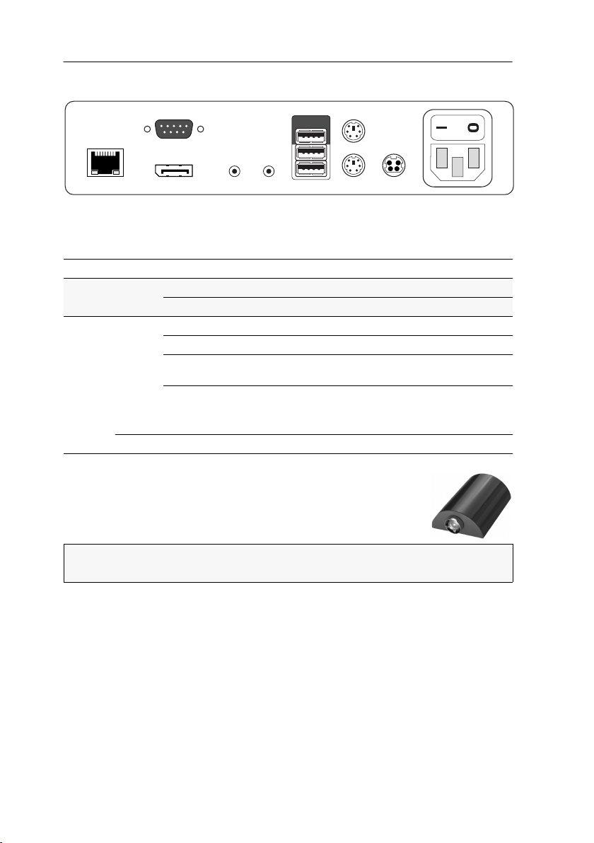
User module »DP-CON«
Micro In
Keyb./MouseSpeaker
Generic
Main Power
Red. Power
DisplayPort Out
LED out
Mouse
Keyb.
Transmission
Back panel
The Transmission interface at the back panel of the user module provides additional
status LEDs. The LEDs have the following meaning:
LED Colour Status Meaning
Left Yellow Off No connection to network.
Blinking Network connection to an end device.
Right Green On A user module is accessing the target module.
Blinking No communication with matrix switch.
Flashing Connection to matrix switch established.
Flickering Keyboard and mouse inputs are forwarded by the accessing
Yellow Flashing A firmware update is carried out.
No user module is accessing.
user module.
The flickering is defined by the user’s entries.
TradeSwitch-LED
The optional TS-LED (order number A6100041) lights if the keyboard and mouse signals of a master console are accessing the user
module.
NOTE:
Keyboard and mouse signals can only access another user module or a tar-
get computer if you activated the TradeSwitch function for the matrix switch.
84 · Target and user modules

User module »DP-CON«
Technical data
DP-CON
Interfaces to
console:
Data transmission to
matrix switch
Video Resolution @ 60 Hz: Max. 1920 × 1200 pixels
Audio Type: Bi-directional extension
Main power supply Type: Internal power pack
Redundant
power supply
optional
Casing Material: Anodised aluminium
Operational
environment
Conformity CE, RoHS
Video: 1 × DisplayPort socket
Keyboard and mouse signals: 2 × PS/2 socket
2 × USB-A
Audio: 2 × 3.5 mm jack socket
USB: 4 × USB-A socket
Tradeswitch-LED: 1 × D-SUB 9 socket
Interface: 1 × RJ45 socket
Transmission length: Max. 140 meters
Resolution @ 85 Hz: Max. 1280 × 1024 pixels
Colour depth: 24 bits
Pixel rate: 25 MHz to 165 MHz
Vertical frequency: 50 Hz to 180 Hz
Horizontal frequency: 30 kHz to 130 kHz
Resolution: 24 Bit
Sampling rate: 96 kHz
Bandwidth: 22 kHz
Connection: 1 × IEC plug(IEC-320 C14)
Current consumption: 100 - 240 VAC; 0.3 A - 0.2 A
Type: External power pack (12 V/2 A)
Connection: 1 × Mini-DIN 4 socket(Power In)
Current consumption: 12 VDC; 1.2 A
Dimensions (W × H × D): 210 × 44 × 210 mm
Weight: Approx. 1.3 kg
Temperature: +5 to +45 °C
Air humidity: < 80%, non-condensing
Target and user modules · 85

User module »DP-CON-2«
User module »DP-CON-2«
With DP-CON-2 user modules, you can connect a console (DisplayPort monitor, keyboard, mouse and audio devices) to two digital matrix switches of the ControlCenter-
Digital or the DVICenter series
At the installed console, matrix switch users can access a target module to operate
the connected computer.
The buttons on the front panel of the user module or configured key combinations
(select keys) let users switch between the connected matrix switches.
.
ADVICE:
to each of the two channels.
Instead of a matrix switch, you can also connect a compatible target module
Package contents
1 × DVI-CON-2 user module
1 × Power cable
Required accessories
2 × Category 5e (or better) twisted pair cables to connect the user module to two
the matrix switches
86 · Target and user modules

User module »DP-CON-2«
Micro In
Keyb./MouseSpeaker
Generic
Main Power
Red. Power
DisplayPort Out
LED out
Mouse
Keyb.
Transmission 1
Transmission 2
Installation
Connecting the console devices
DisplayPort Out: Connect the monitor/projector of the local console.
NOTE:
Check the monitor's manual if the OSD provides a setting for the mode of
the DisplayPort input. If so, select the mode in which the image data is processed
according to the standard
Micro In: Connect the optional microphone of the local console.
Speaker: Connect the optional speakers of the local console.
NOTE:
Console keyboard and console mouse can be connected to the user module’s
USB or PS/2 interfaces.
Keyb.: Connect the PS/2 keyboard of the local console.
Mouse: Connect the PS/2 mouse of the local console.
Keyb./Mouse: Connect the USB keyboard and/or the USB mouse of the local console.
DisplayPort 1.1.
NOTE:
Mixed operation, for example connecting a USB mouse and a PS/2 key-
board is supported, too.
Generic: By default (Keyb./Mouse mode), you can use this interface to connect another
USB input device or supported displays or tablets.
Enable the Generic HID mode (see page 106 ff.) if you want to connect another USB
input device. In this mode, data of the USB input device remains unaltered when
transmitted to the active target module.
IMPORTANT:
with a keyboard connected to the
With enabled Generic HID mode, it is not possible to operate the OSD
Generic socket.
USB Devices: Connect any USB devices to these interfaces. The data stream of the
connected USB device is transmitted to a compatible target module with up to 16
Mbit/s.
LED Out: If you purchased and added the TradeSwitch feature to the matrix switch, con-
nect the optional TS-LED2 here (order number A6100041).
Target and user modules · 87
User module »DP-CON-2«
Connection to the matrix switch
NOTE:
Use category 5e (or better) twisted pair cables to connect the devices.
Transmission 1: Connect this interface to a Dynamic Port (RJ45) of the matrix switch.
Transmission 2: Connect this interface to another Dynamic Port (RJ45) of the matrix
switch.
ADVICE:
module.
You can also connect the Transmission interface directly to a compatible target
Power supply
Main Power: Connect the power cable to the power pack and a power outlet.
Red. Power: If required, connect the power cable of the optional power pack to this
interface. This provides a redundant power supply. Connect the power cable with
the power pack and a power outlet of a different power circuit.
Start-up
Start the user module by pressing the Main Power button of the power pack.
ADVICE:
the matrix switch.
The active hotkey configuration is displayed during the System Startup of
Switching
The buttons on the front panel of the user module or configured key combinations
(select keys) let users switch between the connected matrix switches.
How to switch channels via buttons:
Press the button of the desired channel to activate it.
How to switch channels via key combinations:
On the console keyboard, press Hotkey+Select key.
In the default settings, the select keys are Alt+1 (channel 1) and Alt+2 (channel 2).
88 · Target and user modules

User module »DP-CON-2«
DP-CON-2
Trans.
System
Main
Red.
Video
K/M
Status
Power
Service
Console
Status
Active
Trans. 1
Trans. 2
Status displays
Front panel
The LEDs on the front panel of the user module show the system’s operating status.
Section LED Status Meaning
Power Red. On The optional power pack is connected and the required voltage
Off The optional power pack is not (properly) connected.
Main On The main power supply provides the required voltage.
Off The power button is turned off or the connection with the mains
Status Trans. On The communication with the connected matrix switch or the tar-
Off The communication with a matrix switch or target module of the
System On The device is booting or carries out a firmware update.
Blinking The system is ready for operation.
Console Video On Stable image signal at video input.
Off The incoming video signal could not be detected or it lacks the
K/M On A local keyboard was found.
Off No power at PS/2 interface or USB bus.
Blinking The CPU input (PS/2 or USB) is active and ready.
Trans. Active On Active channel.
Off Inactive channel.
Status On The communication with the connected matrix switch or the tar-
Off The communication with a matrix switch or target module of this
Volt) is available.
(12
could not be established.
Check the proper connection of the power supply cable.
get module of the active channel could be established successfully.
active channel could not be established.
required quality to be processed by the system.
No local keyboard was found.
get module of this channel was established successfully.
active channel could not be established.
Target and user modules · 89

User module »DP-CON-2«
Micro In
Keyb./MouseSpeaker
Generic
Main Power
Red. Power
DisplayPort Out
LED out
Mouse
Keyb.
Transmission 1
Transmission 2
Back panel
The Transmission interface at the back panel of the user module provides additional
status LEDs. The LEDs have the following functions:
LED Colour Status Meaning
left Yellow off No connection to network.
blinking Network connection to an end device.
right Green on A user module is accessing the target module.
blinking No communication with matrix switch.
flashing Connection to matrix switch established.
flickering Keyboard and mouse inputs are forwarded by the accessing
Yellow flashing A firmware update is carried out.
No user module is accessing.
user module.
The flickering is defined by the user’s entries.
TradeSwitch-LED
The optional TS-LED (order number A6100041) lights if the keyboard and mouse signals of a master console are accessing the user
module.
NOTE:
Keyboard and mouse signals can only access another user module or a tar-
get computer if you purchased the TradeSwitch feature for the matrix switch.
90 · Target and user modules

User module »DP-CON-2«
Technical data
DP-CON-2
Interfaces to
console
Data transmission to
matrix switch
Video Resolution @ 60 Hz: Max. 1920 × 1200 pixels
Audio Type: Bi-directional extension
Main power supply Type: Internal power pack
Redundant
power supply
optional
Casing Material: Anodised aluminium
Operational
environment
Conformity CE, RoHS
Video: 1 × DisplayPort socket
Keyboard/mouse signals 2 × PS/2 socket
3 × USB-A
Audio: 2 × 3.5 mm jack socket
USB: 4 × USB-A socket
Tradeswitch-LED: 1 × D-SUB 9 scoket
Interface: 2 × RJ45 socket
Transmission length: Max. 140 meters
Resolution @ 85 Hz: Max. 1280 × 1024 pixels
Colour depth: 24 bits
Pixel rate: 25 MHz to 165 MHz
Vertical frequency: 50 Hz to 180 Hz
Horizontal frequency: 30 kHz to 130 kHz
Resolution: 24 Bit
Sampling rate: 96 kHz
Bandwidth: 22 kHz
Connection: 1 × IEC plug (IEC-320 C14)
Power input: 100 - 240 VAC; 0.3 A - 0.2 A
Type: Portable power pack (12 V/2 A)
Connection: 1 × Mini-DIN 4 socket (Power In)
Power input: 12 VDC; 1.2 A
Dimensions (W × H × D): 210 × 44 × 210 mm
Weight: Approx. 1.3 kg
Temperature: +5 to +45 °C
Air humidity: < 80%, non-condensing
Target and user modules · 91

User module »U2-R-CON«
User module »U2-R-CON«
The U2-R-CON user module transmits USB and RS232 signals from the console to the
U2-R-CPU target module.
Package contents
1 × U2-R-CON user module
1 × Power pack (12V/2A)
1 × Power cable
Required accessory
1 × Category 5e (or better) twisted pair cable to connect the user module to
the matrix switch
92 · Target and user modules

User module »U2-R-CON«
Installation
Connecting the console devices
RS232: Connect the serial end device to this interface.
Trans.: Use a category 5e (or better) twisted pair cable to connect this interface to the
Dynamic
USB 2.0 Devices: Connect up to 4 USB devices to these interfaces.
Power In: Connect the power cable to the power pack and a power outlet.
Port of the USB/RS232 Main Channel that is assigned to the console.
Status displays
The blinking Transmission LEDs show the following connection statuses:
LED Colour Status Meaning
Left Yellow Off No connection to network.
On A user module is accessing the target module.
Right Green On A user module is accessing the target module.
Blinking No communication with matrix switch.
Flashing Connection to matrix switch established successfully.
No user module is accessing.
Target and user modules · 93

User module »U2-R-CON«
Technical data
U2-R-CON
Interfaces to
target computer:
Data transmission to
matrix switch
USB 2.0 Transmission type: Transparent
RS232 Transmission type: Transparent
Main power supply Type: Portable power pack
Housing Material: Anodised aluminium
Operational
environment
Conformity CE, RoHS
USB 2.0: 4 × USB-A
RS232: 1 × D-SUB 9 socket
Interface: 1 × RJ45 socket
Transmission length: Max. 140 metres
Transmission rate: Max. 480 Mbit/s
Transmission rate: Max. 115.200 bit/s
Signals: RxD, TxD, RTS, CTS, DTR, DSR, DCD
Connector: 1 × Mini-DIN 4 socket
Power consumption: 12 VDC/1.5 A
Dimensions (W × H × D): 105 × 26 × 104 mm
Weight: Approx. 240 g
Temperature: + 5 to + 40°C
Air humidity: < 80%, non condensing
94 · Target and user modules

User module »DVI-CON-12V«
User module »DVI-CON-12V«
With DVI-CON-12V user modules, you can connect a console (DVI monitor, keyboard,
mouse and audio devices) to a digital matrix switch of the ControlCenter-Digital or the
DVICenter series.
At the installed console, matrix switch users can access a target module to operate
the connected computer.
Package contents
1 × DVI-CON-12V user module
Required accessories
1 × Category 5e (or better) twisted pair cable to connect the target module to the
matrix switch.
Target and user modules · 95

User module »DVI-CON-12V«
Transmission
Mouse
Keyb.
DVI/VGA Out
Micro In
Speaker Keyb./Mouse
Red. Power
LED Out
Main Power
Installation
Connecting the console devices
NOTE:
Both keyboard and mouse signals can be transmitted to the computer using
the PS/2 or the USB interfaces.
Keyb.: Connect the PS/2 keyboard of the local console.
Mouse: Connect the PS/2 mouse of the local console.
Keyb./Mouse: Connect the USB keyboard and/or USB mouse of the local console.
NOTE:
You can also combine PS/2 and USB devices, for example by connecting a
USB mouse and a PS/2 keyboard.
DVI/VGA Out: Connect the monitor of the local console.
Micro In: Connect the optional microphone of the local console.
Speaker: Connect the optional speakers of the local console.
Connection to the matrix switch
Transmission: Use a category 5e (or better) twisted pair cable to connect the Transmis-
sion interface to a Dynamic Port (RJ45) of the matrix switch.
NOTE:
You can also connect the target module directly to a compatible user module.
Power supply
Main Power: Connect the power cable to the power pack and a power outlet.
Red. Power: If required, connect the power cable of the optional power pack to this
interface. This provides a redundant power supply. Connect the power cable with
the power pack and a power outlet of a different power circuit.
LED Out: If you expanded the functional range of the matrix switch by purchasing the
TradeSwitch feature, connect the optional TS-LED-2 (order number A6100041) to this
interface.
96 · Target and user modules
 Loading...