

G&D DiSign system
Installation and Configuration

About this manual
This manual has been carefully compiled and examined to the state-of-the-art.
G&D neither explicitly nor implicitly takes guarantee or responsibility for the qual-
ity, efficiency and marketability of the product when used for a certain purpose that
differs from the scope of service covered by this manual.
For damages which directly or indirectly result from the use of this manual as well
as for incidental damages or consequential damages, G&D is liable only in cases of
intent or gross negligence.
Caveat Emptor
G&D will not provide warranty for devices that:
Are not used as intended.
Are repaired or modified by unauthorized personnel.
Show severe external damages that was not reported on the receipt of goods.
Have been damaged by non G&D accessories.
G&D will not be liable for any consequential damages that could occur from using
the products.
Proof of trademark
All product and company names mentioned in this manual, and other documents
you have received alongside your G&D product, are trademarks or registered trade
marks of the holder of rights.
© Guntermann & Drunck GmbH 2012. All rights reserved.
Version 1.20 – 25/01/2012
Guntermann & Drunck GmbH
Dortmunder Str. 4a
57234 Wilnsdorf
Germany
Phone +49 2739 8901-100
Fax +49 2739 8901-120
http://www.GDsys.de
sales@GDsys.de
-
i · G&D DiSign system

Safety instructions
Safety instructions
Please read the following safety instructions carefully before you start operating the
G&D product. The instructions well help in avoiding damages to the product and in
preventing possible injuries.
Keep this manual handy for all persons who will be using this product.
Follow all warnings or operating instructions which are on the device or stated in
this user manual.
, Beware of electric shocks
To avoid the risk of electric shock, do not open the device or remove the covers.
If service is required, please contact our technicians.
, Disconnect the main power plug or the power supply before installation
Before installation, ensure that the device has been disconnected from the power
source. Disconnect the main power plug or the power supply of the device.
, Ensure constant access to the power plugs
During the installation of the devices, ensure that the power plugs remain accessible.
! Avoid the risk of tripping over cables
Ensure that there is no risk of tripping over cables.
, Only use a grounded voltage source
Operate this device by using a grounded voltage source.
, Use only the provided G&D power pack
Operate this device with the provided G&D power pack or with the power pack
listed in the manual.
! Operate the device only in designated areas.
The devices are designed for indoor use. Avoid exposure to extreme cold, heat
or humidity.
G&D DiSign system · ii

Contents
Contents
Safety instructions ............................................................................................ ii
DiSign system .................................................................................................. 1
Overview of this manual .................................................................................. 1
Chapter 1: Overview
Installing the DiSign system ............................................................................. 2
Computer module ............................................................................................. 2
Chapter 2: Installation
Display modules ............................................................................................... 3
DiSign-Splitter .................................................................................................. 5
Initiation .......................................................................................................... 5
»CATpro2-Audio-USB« computer module ....................................................... 6
Scope of delivery ............................................................................................... 6
Status displays .................................................................................................. 6
Chapter 3: Components
Technical Data ................................................................................................. 7
Display modules of the DiSign series .................................................................. 8
Scope of delivery ............................................................................................... 8
Status displays .................................................................................................. 9
Setup menu ...................................................................................................... 10
Creating a new session profile in the terminal emulator ................................ 10
Starting the setup menu in the terminal emulator ......................................... 11
Operating the setup menu ........................................................................... 11
Configuration settings ...................................................................................... 12
Retrieving the firmware versions of the display module ................................ 12
Automatic and manual video tuning ........................................................... 12
Resetting the default settings ....................................................................... 14
Technical Data ................................................................................................ 15
DiSign-Splitter-1AV8 ...................................................................................... 17
Scope of delivery .............................................................................................. 17
Status displays ................................................................................................. 17
Technical Data ................................................................................................ 18
iii · G&D DiSign system

1
Overview
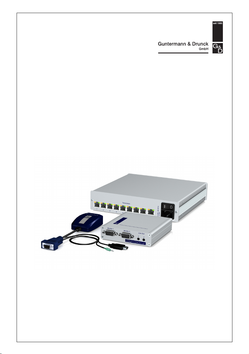
DiSign system
The DiSign system extends and distributes incoming video and audio signals from
one computer to multiple displays and the appropriate audio devices.
The system consists of three components:
Computer module: The computer module is connected to the computer whose video
and audio signals are to be extended and distributed. The computer module pro
cesses the signals and transmits them via twisted pair cabling.
Splitter: The DiSign-Splitter distributes the signals of a connected computer module to
eight outputs. A display module can be connected to each output.
Display module: The display module receives the signals that are transmitted by the
computer module. These signals are processed and output at the connected displays
and the appropriate audio devices.
Overview of this manual
This manual is divided into three chapters that provide a quick overview on how to
apply the components:
Chapter 1: Overview and description of the different system components
Chapter 2: Installation of the components
Chapter 3: Information regarding scope of delivery, status displays and configura-
tion settings (if available) of the different components
-
G&D DiSign system · 1
2
Installation
Installing the DiSign system
Computer module
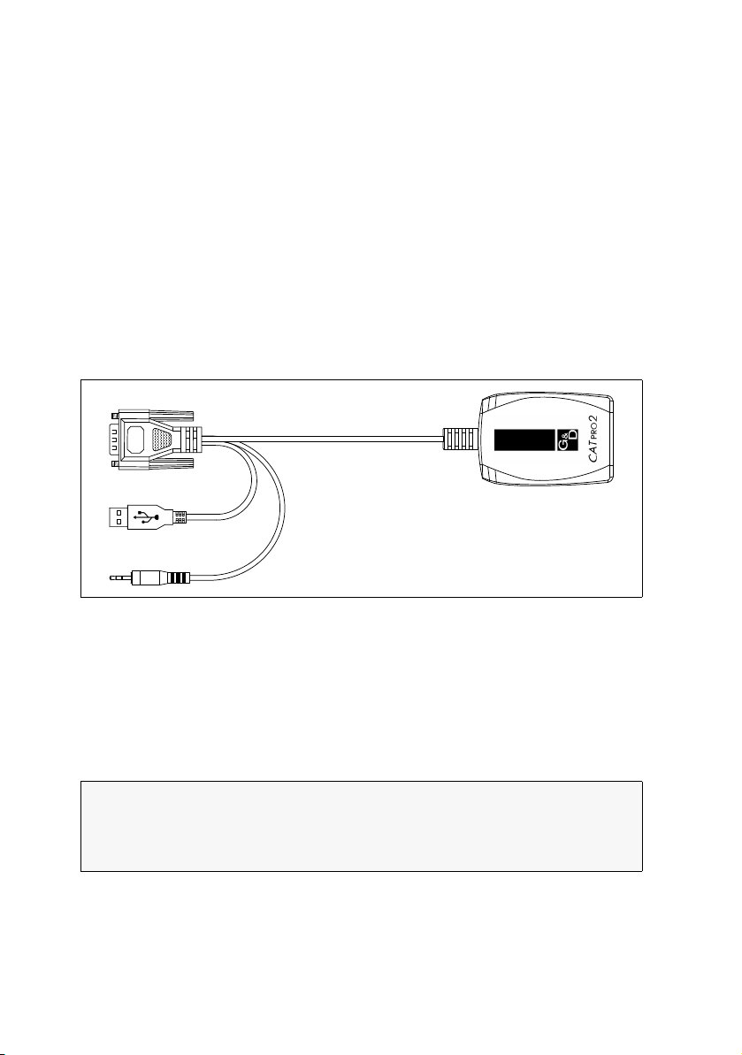
The CATpro2-Audio-USB computer module is connected to the computer whose
video and audio signals are to be extended and distributed. The computer module
processes the signals and transmits them via twisted pair cabling.
Connecting the computer (video and audio source)
Figure 1: Legend of the CATpro2-Audio-USB computer module
Monitor: Connect the 15-pin D-Sub HD plug to the VGA interface of the computer.
USB: Connect the USB-A plug to an available USB interface of the computer.
Speaker: Connect the jack plug to the Speaker interface of the computer.
Connection to splitter
Transmission: Connect this interface to the Signal In interface of the DiSign-Splitter.
NOTE:
If the video and audio signals are distributed to only one display module, it
is not necessary to apply a DiSign-Splitter.
In that case, connect the Transmission interfaces of the computer module and the
display module.
Use a category 5 (or better) twisted pair cabling for that purpose.
2 · G&D DiSign system
Installing the DiSign system
Monitor 1
Monitor 2
Line Out
1
2
Display modules
The display modules of the DiSign series are available in two different variants. Each
variant is provided for different cable distances between the computer module and
the display module:
DiSign-CPU-AV2-sd: Distances up to 50 meters
DiSign-CON-AV2-ld: Distances up to 300 meters
NOTE:
The display modules of both variants are installed as described in the following.
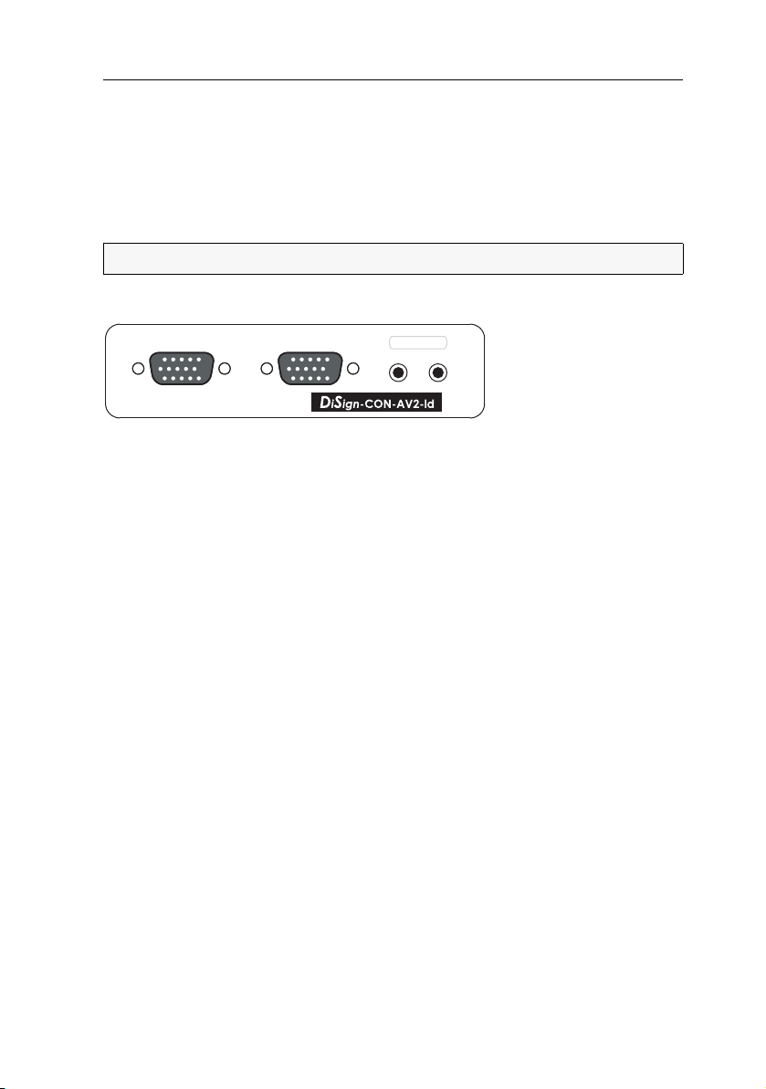
Connecting the interfaces at the front panel
Figure 2: Front view of a display module
Monitor 1: Connect the first display.
Monitor 2: Connect the second display.
Line Out 1: Connect the audio device of the first display.
Line Out 2: Connect the audio device of the second display.
G&D DiSign system · 3

Installing the DiSign system
Transmission PowerPower
Status
Service
1
2
RS232
Connecting the interfaces at the back panel
Figure 3: Back view of a display module
Transmission: Connect this interface to a Transmission interface of the DiSign-Splitter.
NOTE:
If the video and audio signals are distributed to only one display module, it
is not necessary to apply the DiSign-Splitter.
In that case, connect the Transmission interfaces of computer module and display
module.
Use a category 5 (or better) twisted pair cabling for that purpose.
Service: If desired, connect the service cable (USB-Service-2).
Use the service cable to access the setup menu (see page 10) of the display module
with a terminal emulator.
IMPORTANT:
If the service cable (USB-Service-2) is plugged in while the display
module is switched on, no images will be shown on the displays!
RS232 1: This interface is currently not used.
RS232 2: This interface is currently not used.
Power: Plug the cable of the provided power pack into this interface. Then connect
the power cable to the power pack and an AC outlet.
4 · G&D DiSign system
Initiation
Power
Signal In1 82 3 5 6 74
Transmission
DiSign-Splitter
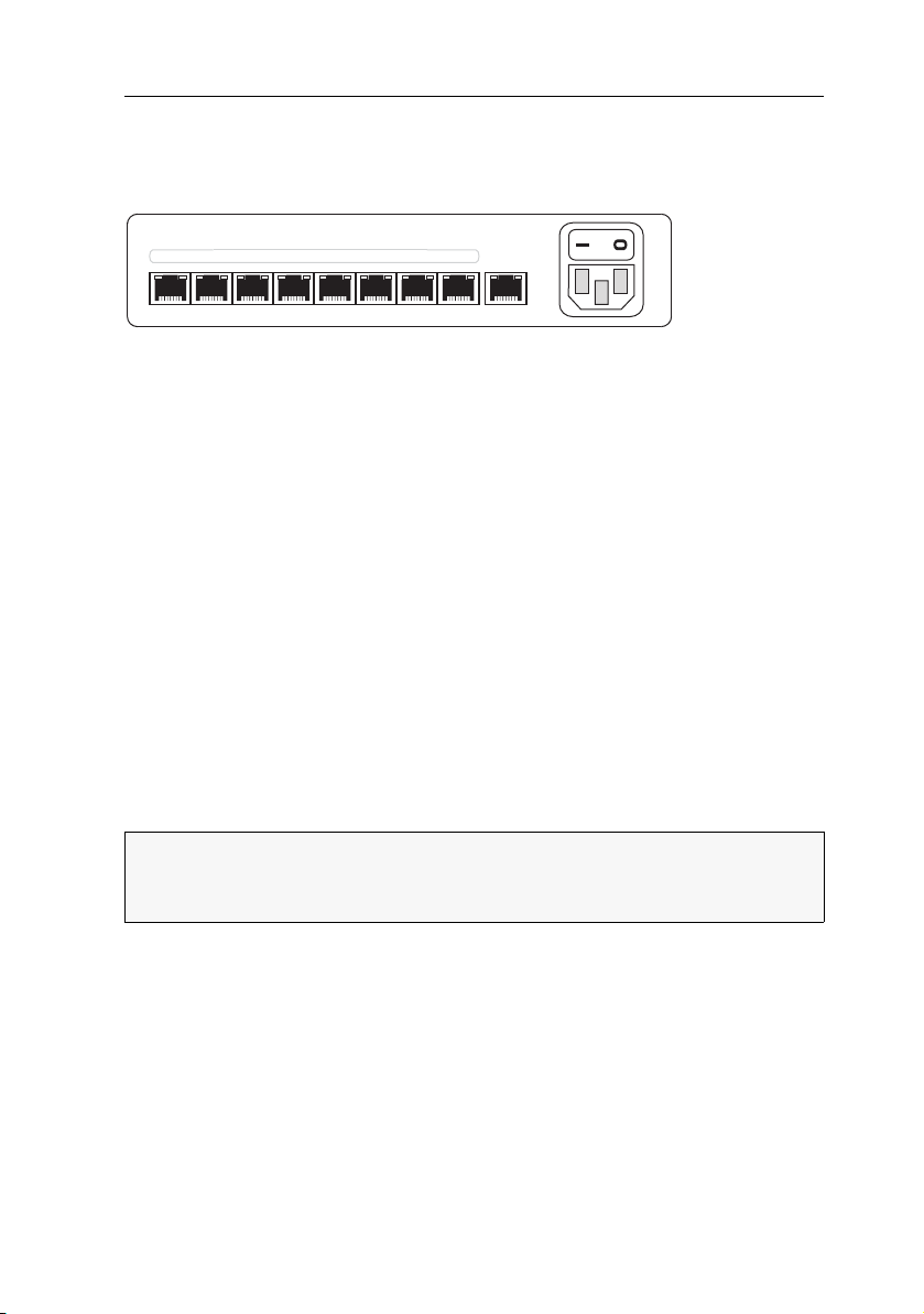
The DiSign-Splitter multiplies the signals of a connected computer module to eight
outputs. A display module can be connected to each output.
Figure 4: Back view of the DiSign-Splitter
Connecting the computer module
Signal In: Use a category 5 (or better) twisted pair cable to connect the Transmission
interface of the computer module to this interface.
Connecting the display modules
Transmission x: Use a category 5 (or better) twisted pair cable to connect the Transmis-
sion interfaces of the different display modules with one of these interfaces of the
DiSign-Splitter.
Establishing the power supply
Power: Connect the provided power cable (PowerCable-2 Standard) to the Power socket.
Initiation
Turn on the computer that is connected to the computer module as well as the
button above the Power socket of the DiSign-Splitter.
After a few seconds the DiSign system is ready for operation.
ADVICE:
If you use the »long distance« variant (DiSign-CON-AV2-ld) with the auto-
matic Video Tuning function, you can manually adjust the image.
Detailed descriptions regarding this function are provided on page 12.
G&D DiSign system · 5

0123
3
Components
»CATpro2-Audio-USB«
computer
Scope of delivery
1 × CATpro2-Audio-USB computer module
Status displays
The blinking Transmission LED signals the following operating states:
Status Transmission LED
Time in seconds
No connection to splitter.
Check if the computer module is properly connected to the splitter.
The connection to the splitter has been successfully established.
module
6 · G&D DiSign system

»CATpro2-Audio-USB« computer module
Technical Data
»CATPRO2-AUDIO-USB« COMPUTER MODULE
Video Signal type: analog video
Resolution: max. 1920 × 1200 @ 60 Hz
Video bandwidth: max. 250 MHz
Horizontal frequency: 50 - 180 Hz
Vertical frequency: 30 - 130 kHz
Audio Resolution: 24 bit
Sampling rate: 48 kHz
Bandwidth: 20 kHz
Interfaces USB: 1 × USB-A
VGA: 1 × D-Sub HD 15
Audio: 1 × jack plug
Transmission: 1 × RJ45 socket
Total length Computer module: 0,3 meters ( incl. cable)
Power supply Type: via USB interface of the computer
Connection: USB
Voltage: +5VDC
Casing Material: plastics
Dimensions (W × H × D): 45 × 20,7 × 70 mm
Weight: ca. 120 g
Operational environment
Conformity CE, RoHs
Temperature: +5 to +45 °C
Air humidity: < 80%, non-condensing
G&D DiSign system · 7

Display modules of the DiSign series
Display modules of the DiSign series
The display modules of the DiSign series are available in two different variants. Each
variant is provided for different cable distances between the computer module and
the display module:
DiSign-CPU-AV2-sd: Distances up to 50 meters
DiSign-CON-AV2-ld: Distances up to 300 meters
NOTE:
The »long distance« variant (DiSign-CON-AV2-ld) provides an automatic
Video Tuning function that automatically detects the different parameters of a cable
connection and uses them to create a video profile.
The video profile ensures that the video image is displayed at all displays in the
best-possible quality.
Additionally, the user can optimise the video profile manually.
Scope of delivery
1 × »DiSign-CPU-AV2-sd« or »DiSign-CON-AV2-ld« display module
1 × power pack (Power-Set 12-Typ 3)
1 × power cable (PowerCable-2 Standard)
1 × service cable (USB-Service-2)
8 · G&D DiSign system

Display modules of the DiSign series
Transmission PowerPower
Status
Service
1
2
RS232
Status displays
Figure 1: Back view of a display module
The LEDs at the back panel of the device enable you to control the operating status
at all times:
Section LED Status Meaning
Front
panel
Trans-
mission
Status blinking Device is ready for operation.
fast blinking The »basic video settings« are missing
Power on The power pack provides the required voltage.
off The power pack is not connected to the device
and/or an AC outlet.
yellow on The communication with the computer module
has been successfully established.
off The communication with the computer module
could not be established.
green on The communication with the computer module
has been successfully established.
off The communication with the computer module
could not be established.
G&D DiSign system · 9

Display modules of the DiSign series
Setup menu
The setup menu of a display module of the DiSign-CON-AV2 series enables you to
adjust the video tuning of the module and retrieve information about the firmware
versions.
To use the setup menu, connect the service interface of the display module to an USB
interface of an computer with an installed terminal emulator (such as HyperTerminal
or PuTTY).
After setting up and establishing a connection to the display module, the setup
menu is displayed in the terminal emulator:
Setup Menu for DiSign CON
Show System Info ...
IVT ...
Set System Defaults ...
'Space': Toggle 'S': Save
Creating a new session profile in the terminal emulator
How to create a new session profile in the terminal emulator:
NOTE:
Before establishing the connection in the terminal emulator, install the
CP210x to UART Bridge VCP device driver.
This driver provides the Service port of the display module as virtual serial inter-
face (COM port). Afterwards, the virtual interface can be selected in the terminal
emulator to establish the connection.
The driver can be downloaded at www.gdsys.de under Downloads > Driver.
Start any terminal emulator(for example HyperTerminal or PuTTY).
Create a new connection and enter the following connection settings:
Bits per second: 115.200
Data bits: 8
Parity: None
Stop bits: 1
Flow control: None
Use the provided data cable to connect the computer to the Service port on the
back of the display module.
10 · G&D DiSign system

Display modules of the DiSign series
Starting the setup menu in the terminal emulator
How to start the setup menu:
1. Start the terminal emulator.
2. Load the session profile of the setup menu and establish the connection.
3. Press the R key in the terminal emulator.
As soon as the connection has been successfully established, the setup menu
(see below) is displayed in the terminal emulator.
NOTE:
It is not required to close the setup menu.
Operating the setup menu
The setup menu lists all settings of the display module in tabular form:
Setup Menu for DiSign CON
Show System Info ...
IVT ...
Set System Defaults ...
'Space': Toggle 'S': Save
How to operate the setup menu:
1. Select an menu item with the arrow keys (up/down).
The active row is marked with angular arrows.
2. Press the Enter key to open the submenu.
G&D DiSign system · 11

Display modules of the DiSign series
Configuration settings
Retrieving the firmware versions of the display module
Use the setup menu to retrieve information about the installed firmware versions.
How to retrieve the firmware versions of the display module:
1. Start the terminal emulator.
2. Load the session profile of the setup menu and establish the connection.
3. Press the R key in the terminal emulator.
4. Use the arrow keys (up/down) to select the menu item Show System Info.
5. Press the Enter key to display the firmware versions of the display module.
6. Press the Q key to return to the main menu.
Automatic and manual video tuning
IMPORTANT:
play module (DiSign-CPU-AV2-sd) only detects and adjusts the video amplification!
After the display module has been put into operation for the first time, a video profile has been created.
This video profile stores information about different cable parameters. This information ensures that the video image is perfectly displayed at the displays.
The video profile can be automatically updated or manually adjusted by the user.
NOTE:
changed, the image quality is influenced.
After the cabling has been changed, it is recommended to carry out the automatic
video tuning (see below).
The Video Tuning function of the »short distance« variant of the dis-
If the cable length between the computer module and display module is
12 · G&D DiSign system

How to carry out the automatic video tuning:
Display modules of the DiSign series
IMPORTANT:
The Video Tuning function of the »short distance« variant of the dis-
play module (DiSign-CPU-AV2-sd) only detects and adjusts the video amplification!
1. Start the terminal emulator.
2. Load the session profile of the setup menu and establish the connection.
3. Press the R key in the terminal emulator.
4. Use the arrow keys (up/down) to select the menu item IVT.
5. Press the Enter key to open the submenu.
6. Press the A key to automatically detect the parameters of the cable connection
and to update the video profile.
7. Press the S key to save the updated video profile.
How to operate the video tuning manually:
IMPORTANT:
The Video Tuning function of the »short distance« variant of the dis-
play module (DiSign-CPU-AV2-sd) only detects and adjusts the video amplification!
1. Start the terminal emulator.
2. Load the session profile of the setup menu and establish the connection.
3. Press the R key in the terminal emulator.
4. Use the arrow keys (up/down) to select the menu item IVT.
5. Press the Enter key to open the submenu.
6. Use the arrow keys (up/down) to select one of the following menu items:
Boost:
Finetuning:
NoiseFilter:
Delay R(ed):
Delay G(reen):
Delay B(lue):
sets video boost
removes colour shadow
sets noise filter
sets delay compensation (red colour signal)
sets delay compensation (green colour signal)
sets delay compensation (blue colour signal)
7. Use the arrow keys (left/right) to reduce or increase the displayed value.
8. Repeat steps 6 and 7 to edit further settings.
9. Press the S key to save the updated video profile or the Q key to restore the original settings and return to the main menu.
G&D DiSign system · 13

Display modules of the DiSign series
Resetting the default settings
This function can be used to restore the default settings of the display module.
IMPORTANT:
All settings are reset and the parameters of the cable connection are
automatically detected.
How to reset the default settings:
1. Start the terminal emulator.
2. Load the session profile of the setup menu and establish the connection.
3. Press the R key in the terminal emulator.
4. Use the arrow keys (up/down) to select the menu item Set System Defaults.
5. Press the Enter key to restore the default settings or press the Q key to cancel the
process.
14 · G&D DiSign system

Display modules of the DiSign series
Technical Data
»DISIGN-CPU-AV2-SD« DISPLAY MODULE
Video Signal type:: analog video (VGA)
Video resolution: max. 1920 x 1200 @ 60 Hz
Video bandwidth: 180 MHz
Horizontal frequency: 50 - 180 Hz
Vertical frequency: 30 - 130 kHz
Audio Type: analog
Sampling rate: 48 kHz
Resolution: 24 bit
Bandwidth: 22 kHz
Interfaces Monitor: 2 × VGA socket
Line Out: 2 × 3,5-mm jack plug
Transmission: 1 × RJ45 socket
Service: 1 × mini USB port (type B)
RS232:
currently not used
Power: 1 × mini DIN 4 port
Transmission length computer module
Power Supply Type: power pack
Casing Material: anodised aluminium
Operational environment
Conformity CE, RoHs
to display module:
Connection: mini DIN 4 port
Current consumption:
max.
Dimensions (W × H × D): 105 × 26 × 160 mm
Temperature: +5 to +45 °C
Air humidity: < 80%, non-condensing
2 × RJ11 port
max. 50 meters
400 mA@12 VDC
G&D DiSign system · 15

Display modules of the DiSign series
»DISIGN-CPU-AV2-LD« DISPLAY MODULE
Video Signal type:: analog video (VGA)
Video resolution: max. 1920 x 1200 @ 60 Hz
Video bandwidth: 180 MHz
Horizontal frequency: 50 - 180 Hz
Vertical frequency: 30 - 130 kHz
Audio Type: analog
Sampling rate: 48 kHz
Resolution: 24 bit
Bandwidth: 22 kHz
Interfaces Monitor: 2 × VGA socket
Line Out: 2 × 3,5-mm jack plug
Transmission: 1 × RJ45 socket
Service: 1 × mini USB port (type B)
RS232:
2 × RJ11 port
currently not used
Power: 1 × mini DIN 4 port
Transmission length computer module
max. 300 meters
to display module:
Power Supply Type: power pack
Connection: mini DIN 4 port
Current consumption (max): 400 mA@12 VDC
Power consumption Standby: 1,6 W@12 VDC
Operation (max.): 4,2 W@12 VDC
Casing Material: anodised aluminium
Dimensions (W × H × D): 105 × 26 × 160 mm
Operational environment
Temperature: +5 to +45 °C
Air humidity: < 80%, non-condensing
Conformity CE, RoHs
16 · G&D DiSign system
DiSign-Splitter-1AV8
Service
DS -S
i ign plitter-1AV8
D S -S
i ign plitter-1AV8
Active
Status
Device
DiSign-Splitter-1AV8
Scope of delivery
1 × DiSign-Splitter-1AV8
1 × power cable (PowerCable-2 Standard)
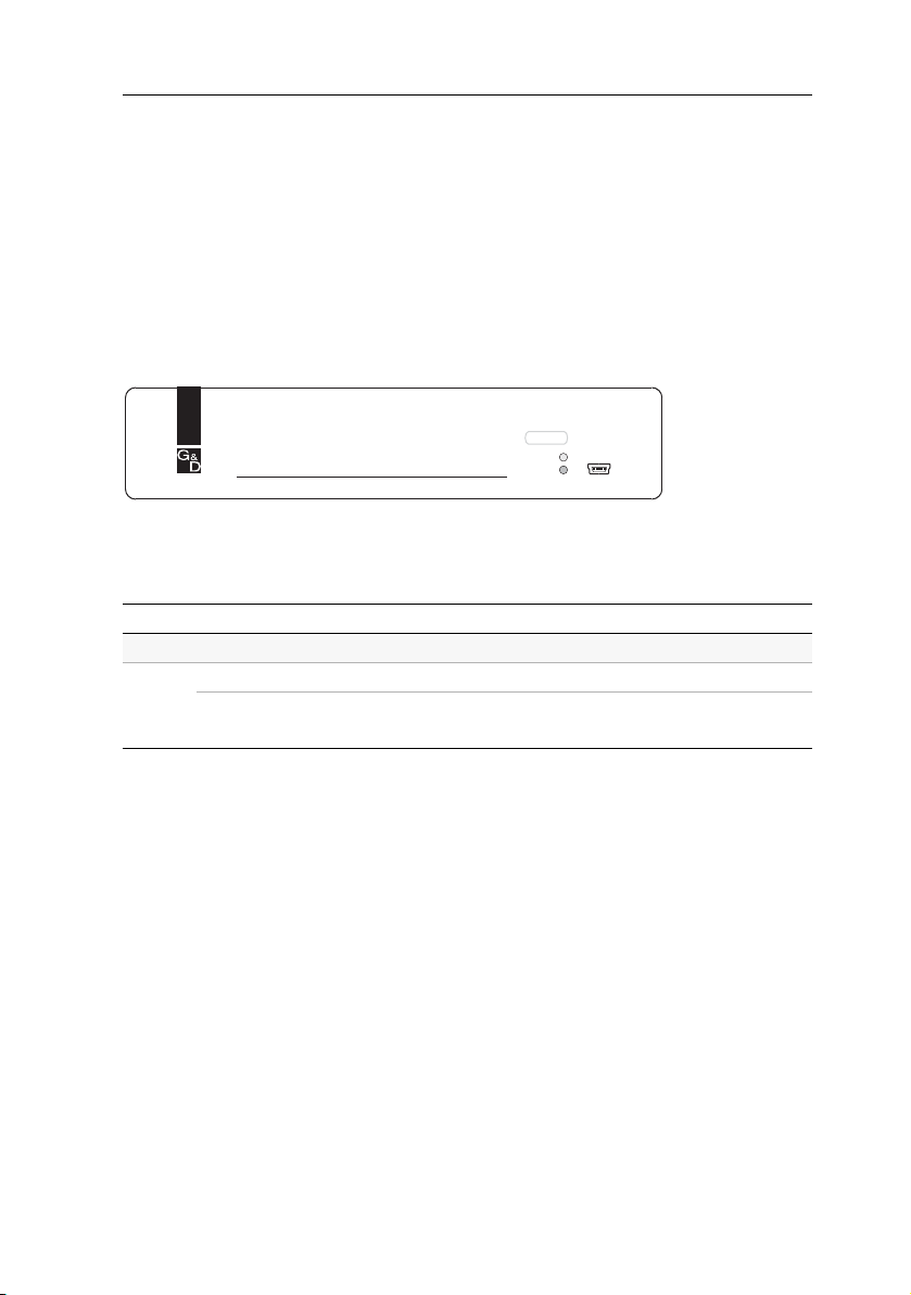
Status displays
The LEDs at the front panel of the device enable you to control the operating status
at all times:
Figure 2: Status displays at the front panel of the DiSign-Splitter
The following table lists the meanings of the different LEDs:
LED Status Meaning
Active This LED is currently not used!
Status lighting The connection to the display module has been successfully established.
blinking No connection to display module.
Check the cable connection.
Table 1: Meaning of the different LEDs
G&D DiSign system · 17

DiSign-Splitter-1AV8
Technical Data
DISIGN-SPLITTER-1AV8
Video Signal type:: analog video (VGA)
Video resolution: max. 1920 x 1200 @ 60 Hz
Video bandwidth: 180 MHz
Horizontal frequency: 50 - 180 Hz
Vertical frequency: 30 - 130 kHz
Audio Mode: digital forwarding of incoming data
Interfaces to display modules: 8 × RJ45 socket
to computer module: 1 × RJ45 socket
Service socket: 1 × mini USB socket (type B)
Power supply Type: internal power pack
Connection: IEC plug (IEC-320 C14)
Voltage: 100-240VAC/60-50Hz
Current consumption (max.): 100 mA@240VAC; 200 mA@100VAC
Power consumption (max.): 7,6W@240VAC; 6,9W@100VAC
Casing Material: anodised aluminium
Dimensions (W × H × D): 210 × 44 × 210 mm
Operational environment
Conformity CE, RoHs
Temperature: +5 to +45 °C
Air humidity: < 80%, non-condensing
18 · G&D DiSign system

Notes
G&D DiSign system · 19

Guntermann & Drunck GmbH
Dortmunder Str. 4a
57234 Wilnsdorf
Germany
Phone +49 2739 8901-100
Fax +49 2739 8901-120
http://www.GDsys.de
sales@GDsys.de
A9200082
 Loading...