

Guntermann & Drunck ControlCenter-Compact-16C, ControlCenter-Compact-32C, ControlCenter-Compact-48C, ControlCenter-Compact-64C, ControlCenter-Compact-80C Installation And Operation Manual

Guntermann & Drunck GmbH
www.gdsys.de
ControlCenter-Compact
A9100282-1.00
Installation und Bedienung
DE
EN
Installation and Operation

i · G&D ControlCenter-Compact
Zu dieser Dokumentation
Diese Dokumentation wurde mit größter Sorgfalt erstellt und nach dem Stand der
Technik auf Korrektheit überprüft.
Für die Qualität, Leistungsfähigkeit sowie Marktgängigkeit des G&D-Produkts zu
einem bestimmten Zweck, der von dem durch die Produktbeschreibung abgedeck
ten Leistungsumfang abweicht, übernimmt G&D weder ausdrücklich noch stillschweigend die Gewähr oder Verantwortung.
Für Schäden, die sich direkt oder indirekt aus dem Gebrauch der Dokumentation
ergeben, sowie für beiläufige Schäden oder Folgeschäden ist G&D nur im Falle des
Vorsatzes oder der groben Fahrlässigkeit verantwortlich.
Gewährleistungsausschluss
G&D übernimmt keine Gewährleistung für Geräte, die
nicht bestimmungsgemäß eingesetzt wurden.
nicht autorisiert repariert oder modifiziert wurden.
schwere äußere Beschädigungen aufweisen, welche nicht bei Lieferungserhalt
angezeigt wurden.
durch Fremdzubehör beschädigt wurden.
G&D haftet nicht für Folgeschäden jeglicher Art, die möglicherweise durch den
Einsatz der Produkte entstehen können.
Warenzeichennachweis
Alle Produkt- und Markennamen, die in diesem Handbuch oder in den übrigen
Dokumentationen zu Ihrem G&D-Produkt genannt werden, sind Warenzeichen
oder eingetragene Warenzeichen der entsprechenden Rechtsinhaber.
Impressum
© Guntermann & Drunck GmbH 2016. Alle Rechte vorbehalten.
Version 1.00 – 06.10.2016
Firmware: 1.0.000
Guntermann & Drunck GmbH
Dortmunder Str. 4a
57234 Wilnsdorf
Germany
Telefon +49 (0) 2739 8901-100
Telefax +49 (0) 2739 8901-120
http://www.GDsys.de
sales@GDsys.de

Inhaltsverzeichnis
G&D ControlCenter-Compact · ii
Deutsch
Inhaltsverzeichnis
Sicherheitshinweise .......................................................................................... 1
Das KVM-Matrixsystem »ControlCenter-Compact« ........................................ 2
Erweiterung eines KVM-Matrixsystems ............................................................. 2
Das Zentralmodul ............................................................................................ 3
Lieferumfang .................................................................................................... 3
Erforderliches Zubehör ..................................................................................... 3
Installation ....................................................................................................... 4
Stromversorgung ............................................................................................... 4
Installation und Anschluss der Arbeitsplatzmodule ............................................ 5
Anschluss der Geräte des Arbeitsplatzes an die Arbeitsplatzmodule .............. 5
Anschluss der Arbeitsplatzmodule an das Zentralmodul ............................... 5
Installation und Anschluss der Target-Module ................................................... 6
Anschluss der Target-Computer an die Target-Module ................................. 6
Anschluss der Target-Module an das Zentralmodul ...................................... 6
Netzwerkschnittstellen ...................................................................................... 7
Empfehlungen zum Twisted-Pair-Kabel ........................................................... 8
Erstkonfiguration der Netzwerkeinstellungen .................................................. 9
Konfiguration der Netzwerkschnittstellen .......................................................... 9
Konfiguration der »globalen« Netzwerkeinstellungen ....................................... 10
Verwendung des Reset-Tasters ....................................................................... 11
Wiederherstellung der Standardeinstellungen ................................................... 11
Temporäre Deaktivierung der Netzfilterregeln .................................................. 12
Konfiguration der Dynamic Ports .................................................................. 13
Automatischer Port-Modus ............................................................................. 13
Besonderheiten bei Kaskadierung eines Matrixswitches .............................. 13
Kompatibilitätsmodus ..................................................................................... 14
Erweiterung des KVM-Matrixsystems ............................................................ 15
Kaskadierung (Standard) ........................................................................... 15
KVM Matrix-Grid™ (kostenpflichtig) ........................................................ 15
Kaskadierung eines Matrixswitches ................................................................. 16
Konfiguration und Signalisierung der Portaufteilung ........................................ 16
Anschluss eines Slave-Zentralmoduls ............................................................... 17
Festlegung des Kaskadenmodus des Zentralmoduls .......................................... 17
Erweiterung der schaltbaren Signale .............................................................. 19
Erweiterung durch Kanal-Gruppierung ............................................................ 19
Erweiterung durch Port-Gruppierung ............................................................... 20
Eine neue Kanal-Gruppierung erstellen ...................................................... 20
Module einer Kanal-Gruppierung hinzufügen oder entfernen ...................... 21
Eine Kanal-Gruppierung löschen ............................................................... 22

Inhaltsverzeichnis
iii · G&D ControlCenter-Compact
Erweiterung durch Stacking ............................................................................. 23
Anschluss eines Stack-Matrixswitches ......................................................... 23
Bus-Adresse eines Matrixswitches einstellen ............................................... 24
Statusanzeigen ................................................................................................ 25
Technische Daten ........................................................................................... 27
Allgemeine Eigenschaften der Serie .................................................................. 27
Spezifische Eigenschaften der Geräte ................................................................ 27

Sicherheitshinweise
G&D ControlCenter-Compact · 1
Deutsch
Sicherheitshinweise
Bitte lesen Sie die folgenden Sicherheitshinweise aufmerksam durch, bevor Sie das
G&D-Produkt in Betrieb nehmen. Die Hinweise helfen Schäden am Produkt zu ver
-
meiden und möglichen Verletzungen vorzubeugen.
Halten Sie diese Sicherheitshinweise für alle Personen griffbereit, die dieses Produkt
benutzen werden.
Befolgen Sie alle Warnungen oder Bedienungshinweise, die sich am Gerät oder in
dieser Bedienungsanleitung befinden.
, Vorsicht vor Stromschlägen
Um das Risiko eines Stromschlags zu vermeiden, sollten Sie das Gerät nicht öff-
nen oder Abdeckungen entfernen. Im Servicefall wenden Sie sich bitte an unsere
Techniker.
, Ziehen Sie den Netzstecker des Geräts vor Installationsarbeiten
Stellen Sie vor Installationsarbeiten sicher, dass das Gerät spannungsfrei ist. Zie-
hen Sie den Netzstecker oder die Spannungsversorgung am Gerät ab.
, Ständigen Zugang zu den Netzsteckern der Geräte sicherstellen
Achten Sie bei der Installation der Geräte darauf, dass die Netzstecker der
Geräte jederzeit zugänglich bleiben.
, Lüftungsöffnungen nicht verdecken
Lüftungsöffnungen verhindern eine Überhitzung des Geräts. Verdecken Sie
diese nicht.
! Stolperfallen vermeiden
Vermeiden Sie bei der Verlegung der Kabel Stolperfallen.
, Geerdete Spannungsquelle verwenden
Betreiben Sie dieses Gerät nur an einer geerdeten Spannungsquelle.
, Verwenden Sie ausschließlich das G&D-Netzteil
Betreiben Sie dieses Gerät nur mit dem mitgelieferten oder in der Bedienungsan-
leitung aufgeführten Netzteil.
! Betreiben Sie das Gerät ausschließlich im vorgesehenen Einsatzbereich
Die Geräte sind für eine Verwendung im Innenbereich ausgelegt. Vermeiden Sie
extreme Kälte, Hitze oder Feuchtigkeit.

Das KVM-Matrixsystem »ControlCenter-Compact«
2 · G&D ControlCenter-Compact
Das KVM-Matrixsystem
»ControlCenter-Compact«
Ein KVM-Matrixsystem der ControlCenter-Compact-Serie besteht aus mindestens je
einem Zentralmodul, einem Arbeitsplatzmodul und einem Target-Modul.
Das Zentralmodul der ControlCenter-Compact-Serie ist die zentrale Komponente des
KVM-Matrixsystems. Hieran werden die Arbeitsplatz- und Target-Module ange
-
schlossen.
Das KVM-Matrixsystem ermöglicht die Aufschaltung eines Arbeitsplatzmoduls auf
ein Target-Modul. Durch die Aufschaltung wird das Videobild des am Target-Modul
angeschlossenen Computers auf dem Arbeitsplatz-Monitor angezeigt. Mit der Tasta
-
tur und Maus des Arbeitsplatzes bedienen Sie den aufgeschalteten Computer.
In der ControlCenter-Compact-Serie sind folgende Varianten verfügbar:
An die Dynamic Ports können Sie wahlweise Arbeitsplatz- oder Target-Module
anschließen.
Erweiterung eines KVM-Matrixsystems
Falls die Anzahl der Ports eines Matrixswitches für den gewünschten Einsatzzweck
nicht ausreicht, können Sie mehrere Matrixswitches zu einem Verbund zusammen
-
fügen.
Hierfür stehen die Technologien Kaskadierung (Standard) und KVM Matrix-Grid™
(kostenpflichtig) zur Verfügung.
Informationen zu diesen Technologien finden im Kapitel Erweiterung des KVM-
Matrixsystems ab Seite 15.
Variante Dynamic-Ports für Anschluss der Module
ControlCenter-Compact-16C 16 × RJ45-Buchse (CAT)
ControlCenter-Compact-32C 32 × RJ45-Buchse (CAT)
ControlCenter-Compact-48C 48 × RJ45-Buchse (CAT)
ControlCenter-Compact-64C 64 × RJ45-Buchse (CAT)
ControlCenter-Compact-80C 80 × RJ45-Buchse (CAT)

Das Zentralmodul
G&D ControlCenter-Compact · 3
Deutsch
Das Zentralmodul
Das Zentralmodul ControlCenter-Compact ist die zentrale Komponente eines KVMMatrixsystems. An das Zentralmodul werden die Target- sowie die Arbeitsplatzmo
-
dule angeschlossen.
Die Aufschaltung eines Arbeitsplatzmoduls auf ein Target-Modul wird durch das
Zentralmodul gesteuert.
Lieferumfang
1 × Zentralmodul ControlCenter-Compact
2 × Stromversorgungskabel (PowerCable-2 Standard)
1 × Rackmount-Set
1 × Service-Kabel (USB-Service-2)
1 × Handbuch »Installationsanleitung«
1 × Handbuch-Satz »Target-und Arbeitsplatzmodule«
Standard-Varianten
Geräte mit integriertem USB
DP-HR-Varianten
DP-HR-U-Varianten
1 × Handbuch »Bedienung & Konfiguration«
1 × Handbuch »Webapplikation Config Panel«
Erforderliches Zubehör
Ein bzw. zwei Twisted-Pair-Kabel der Kategorie 5e (oder höher) zum Anschluss
des Zentralmoduls an ein bzw. zwei lokale Netzwerke.
Installation
4 · G&D ControlCenter-Compact
Installation
Auf den folgenden Seiten wird die Installation der Komponenten des KVM-Systems
beschrieben.
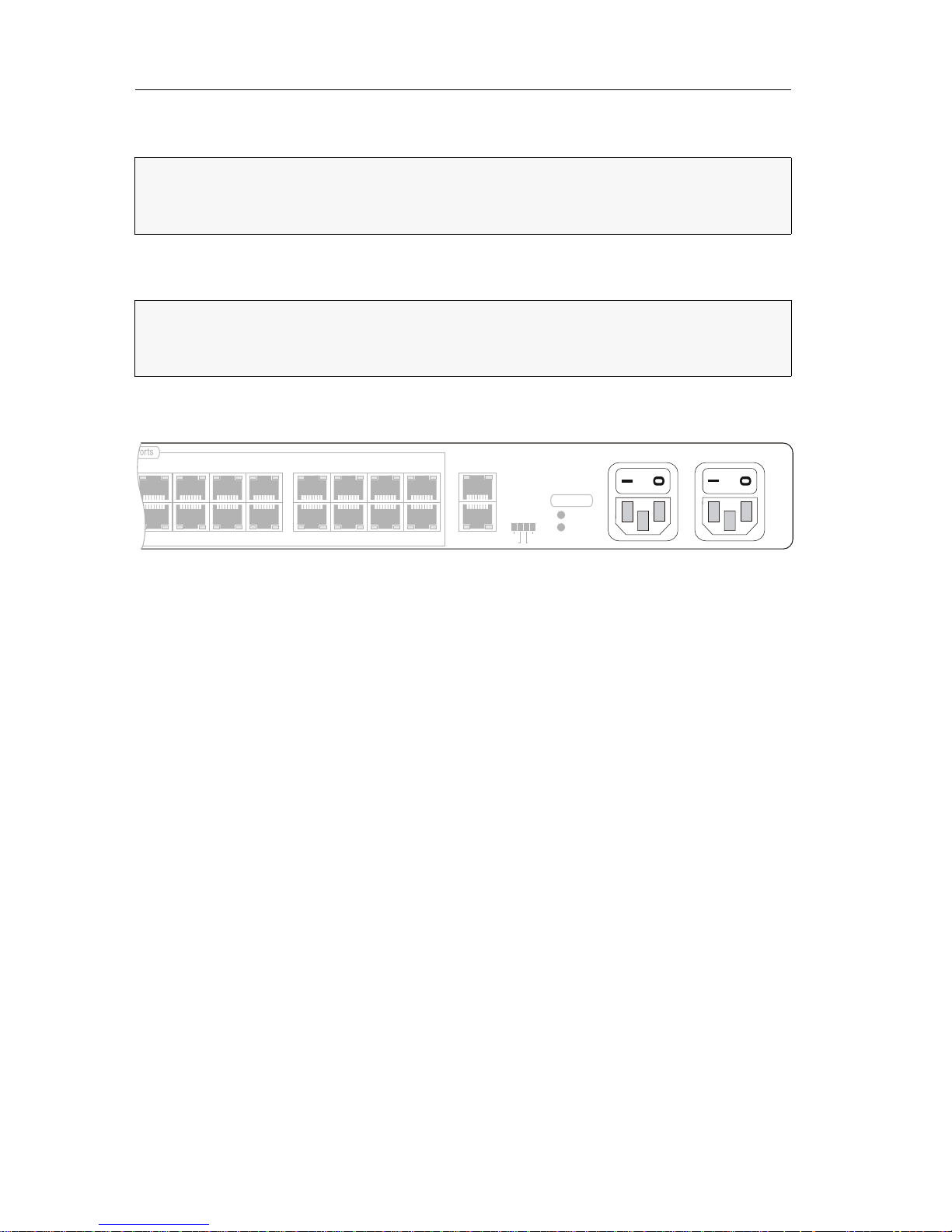
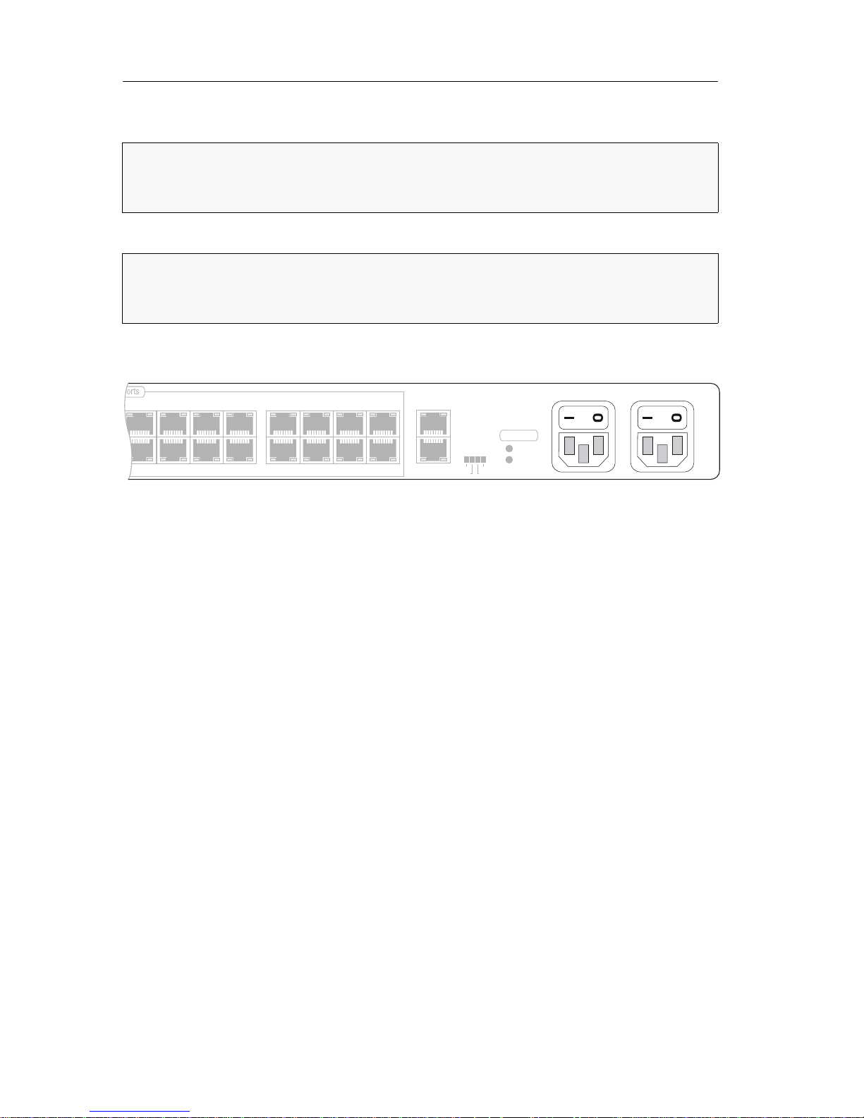
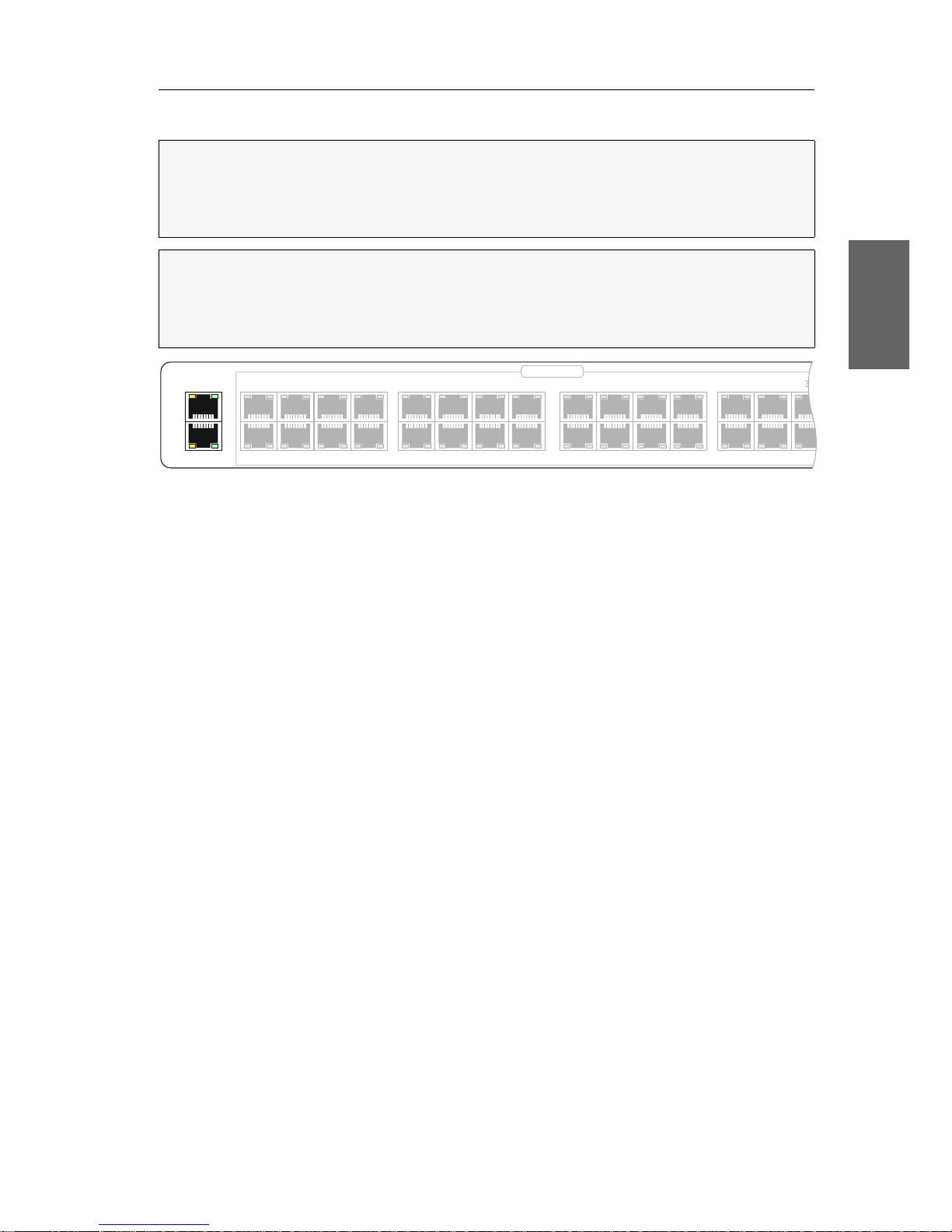
Stromversorgung
Main Power: Schließen Sie ein mitgeliefertes Stromversorgungskabel an. Verbinden
Sie das Stromversorgungskabel mit einer Netzsteckdose und schalten Sie den Netz
-
schalter ein.
Red. Power: Schließen Sie ggf. ein mitgeliefertes Stromversorgungskabel zur Herstel-
lung einer redundanten Stromversorgung an. Verbinden Sie das Stromversorgungskabel mit einer Netzsteckdose eines anderen Stromkreises und schalten Sie den
Netzschalter ein.
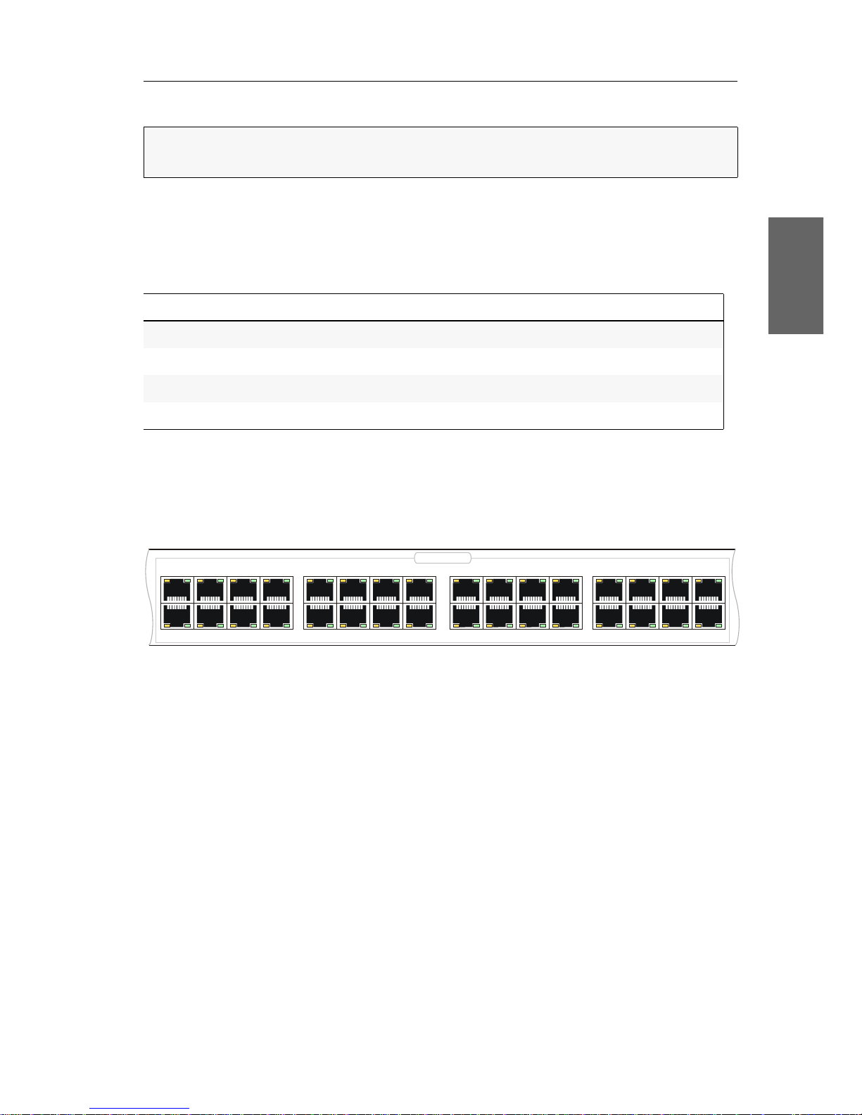
HINWEIS:
Die Skizzen zeigen die Variante ControlCenter-Compact-32C. Die verschiedenen Varianten unterscheiden sich in der Anzahl der Dynamic-Ports für den
Anschluss der Arbeitsplatz- und Target-Module.
HINWEIS:
Stellen Sie bei der Standortwahl des Gerätes sicher, dass die zulässige
Umgebungstemperatur
(siehe Technische Daten auf Seite 27) in der unmittelbaren
Nähe eingehalten und nicht durch andere Geräte beeinflusst wird.
18 20
22
24
17 19 21 23
26 28 30
32
31
29
2725
Power
Red.
Main
Bus Out
Bus In
Status
Ident.
Fail
Portfunction
Main Power
Red. Power
Installation
G&D ControlCenter-Compact · 5
Deutsch
Installation und Anschluss der Arbeitsplatzmodule
Anschluss der Geräte des Arbeitsplatzes an die
Arbeitsplatzmodule
Schließen Sie die Gerätes des Arbeitsplatzes an die verschiedenen Arbeitsplatz-
module an.
Die erforderlichen Schritte werden in den mitgelieferten Handbüchern der
Module beschrieben:
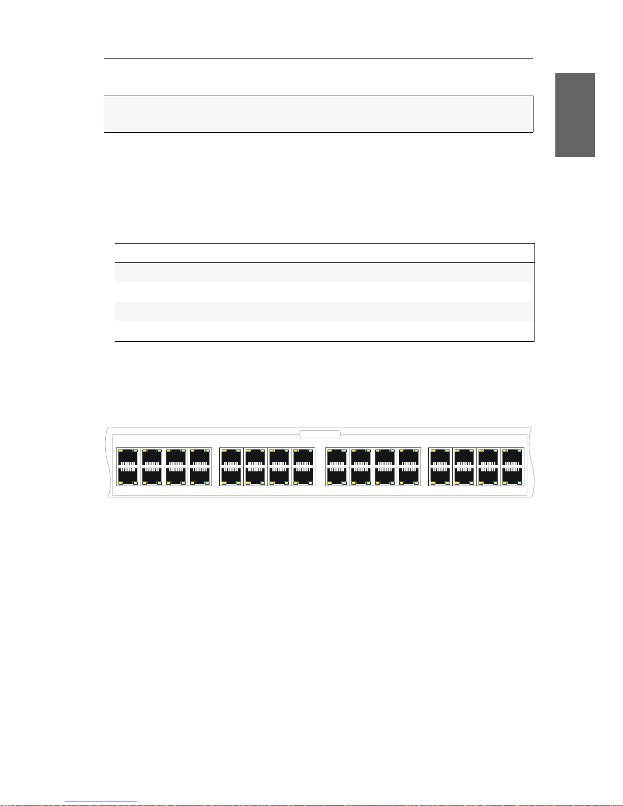
Anschluss der Arbeitsplatzmodule an das Zentralmodul
Verbinden Sie die Transmission-Schnittstellen der einzelnen Arbeitsplatzmodule
mit jeweils einem Dynamic
Port des Zentralmoduls.
Verwenden Sie hierzu eine Twisted-Pair-Verkabelung der Kategorie 5e (oder höher)
HINWEIS:
Die maximale Distanz zwischen einem Arbeitsplatzmodul und dem Zen-
tralmodul beträgt 140 Meter.
Handbuch Artikelnummer Download-Link
Standard-Varianten A9100221 http://gdsys.de/A9100221
Geräte mit integriertem USB A9100249 http://gdsys.de/A9100249
DP-HR-Varianten A9100259 http://gdsys.de/A9100259
DP-HR-U-Varianten A9100260 http://gdsys.de/A9100260
10 12 14 16
1513119
246
8
753
1
18 20
22
24
17 19 21 23
26 28 30
32
31
29
2725
Dynamic Ports

Installation
6 · G&D ControlCenter-Compact
Installation und Anschluss der Target-Module
Anschluss der Target-Computer an die Target-Module
Schließen Sie die Target-Computer an die verschiedenen Target-Module an.
Die erforderlichen Schritte werden in den mitgelieferten Handbüchern der
Module beschrieben:
Anschluss der Target-Module an das Zentralmodul
Verbinden Sie die Trans.-Schnittstellen der einzelnen Target-Module mit jeweils
einem Dynamic
Port des Zentralmoduls.
Verwenden Sie hierzu eine Twisted-Pair-Verkabelung der Kategorie 5e (oder höher).
WICHTIG:
Die maximale Distanz zwischen einem Target-Modul und dem Zentralmodul beträgt 140 Meter.
Handbuch Artikelnummer Download-Link
Standard-Varianten A9100221 http://gdsys.de/A9100221
Geräte mit integriertem USB A9100249 http://gdsys.de/A9100249
DP-HR-Varianten A9100259 http://gdsys.de/A9100259
DP-HR-U-Varianten A9100260 http://gdsys.de/A9100260
WICHTIG:
Das Target-Modul DVI-CPU-UC ist mit zwei Trans.-Schnittstellen ausgestattet. Verbinden Sie ausschließlich eine Trans.-Schnittstelle des Target-Moduls
mit diesem Zentralmodul!
10 12 14 16
1513119
246
8
753
1
18 20
22
24
17 19 21 23
26 28 30
32
31
29
2725
Dynamic Ports
Installation
G&D ControlCenter-Compact · 7
Deutsch
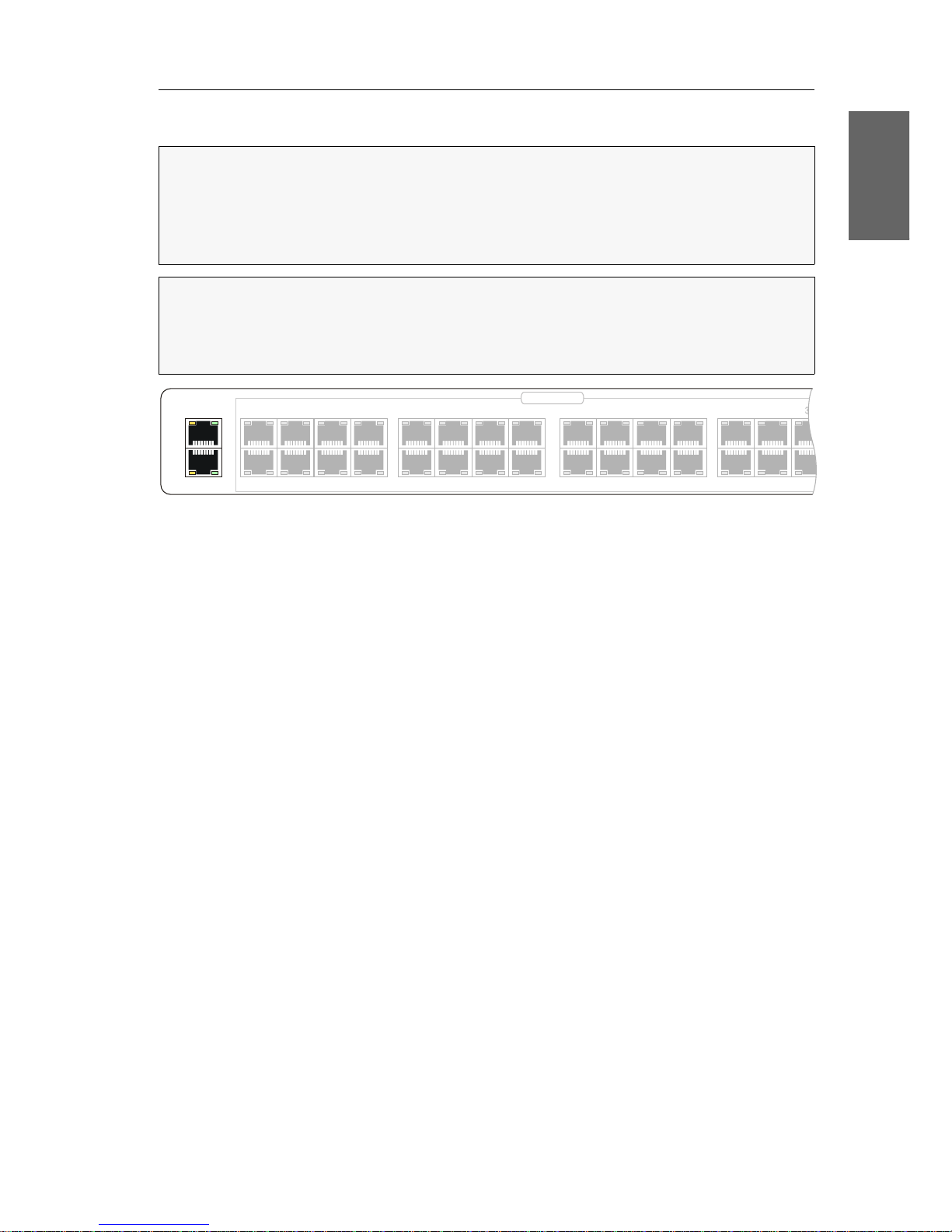
Netzwerkschnittstellen
Network A: Stecken Sie ggf. ein als Zubehör erhältliches Twisted-Pair-Kabel der Kate-
gorie 5e (oder höher) ein.
Das andere Ende des Kabels ist mit einer Netzwerkschnittstelle eines lokalen Netzwerks zu verbinden.
Network B: Stecken Sie ggf. ein als Zubehör erhältliches Twisted-Pair-Kabel der Kate-
gorie 5e (oder höher) ein.
Das andere Ende des Kabels ist mit einer Netzwerkschnittstelle eines lokalen Netzwerks zu verbinden.
HINWEIS:
Die Konfiguration des Zentralmoduls über die Webapplikation
Config
Panel und der Einsatz der erweiterten Netzwerkfunktionalitäten (z. B.
Authentifizierung gegenüber Verzeichnisdiensten, Zeitsynchronisation über einen
NTP-Server, Netzfilter oder Syslog) erfordert eine Verbindung des Zentralmoduls
mit einem (oder zwei) lokalen Netzwerk(en).
WICHTIG:
Falls Sie mit der Webapplikation die Konfiguration der Dynamic Ports
geändert bzw. die Signalisierung der Modi der Dynamic Ports aktiviert haben, been
den Sie zunächst die Verbindung zur Webapplikation und entfernen Sie das Twisted-Pair-Kabel aus der Netzwerkschnittstelle des Zentralmoduls.
Network A
Network B
10 12 14 16
1513119
246
8
753
1
18 20
22
24
17 19 21 23
26 28
29
2725
Dynamic Ports

Empfehlungen zum Twisted-Pair-Kabel
8 · G&D ControlCenter-Compact
Empfehlungen zum Twisted-Pair-Kabel
Die Übertragung aller Signale des ControlCenter-Compact-Systems erfolgt über TwistedPair-Kabel der Kategorie 5e (oder höher).
Die Datenübertragung ist mit handelsüblichen, standardkonformen Twisted-PairKabeln der Kategorie 5e (oder höher) bis mindestens 80 Meter zuverlässig möglich.
Die tatsächlich erreichbare Entfernung hängt von der Qualität des verwendeten
Kabels ab. Hochqualitative S-STP-Leitungen mit einem Drahtdurchmesser der
Codierung AWG22 können bis zu 140 Meter überbrücken.
Patchleitungen mit einem Drahtdurchmesser der Codierung AWG26 überbrücken
maximal 80 Meter Entfernung.
Um einen zuverlässigen Betrieb auch in schwierigen Umgebungen zu gewährleisten, sind für Längen über 80 Metern, Kabel der Codierung AWG24 oder besser zu
verwenden:
Die folgenden Kabel haben während des Testbetriebs unter Laborbedingungen die
besten Ergebnisse erzielt:
HINWEIS:
Das Verbinden mehrerer Teilstrecken einer Kabelverbindung über
Patchfelder und Anschlussdosen ist möglich. Die Einbindung aktiver Komponen
-
ten wie Netzwerk-Switches, Hubs oder Repeater, ist hingegen nicht zulässig.
Drahtstärke Kabeltyp Kategorie Empfehlung
AWG22 Installation 5e, 6 oder 7 bis 140 Meter
AWG24 Installation 5e, 6 oder 7 bis 120 Meter
AWG26/27 Patchkabel 5e, 6 oder 7 bis 80 Meter
HINWEIS:
Die in der obigen Tabelle angegebenen Längen stellen die Summe aller
Teilstücke zwischen den Geräten dar.
bis 80 Meter: Dätwyler uninet® 7702 flex
Patchkabel
bis 100 Meter: Dätwyler uninet® 5502 AWG24 S-STP
Installationskabel mit Steckern
bis 140 Meter: Kerpen MegaLine® G12-150 S/F AWG22
Installationskabel mit Buchsen
Dätwyler uninet® 7702 AWG 22
Installationskabel mit Buchsen

Erstkonfiguration der Netzwerkeinstellungen
G&D ControlCenter-Compact · 9
Deutsch
Erstkonfiguration der Netzwerkeinstellungen
Grundlegende Voraussetzung für den Zugriff auf die Webapplikation Config Panel
und den Einsatz erweiterter Netzwerkfunktionalitäten ist die Konfiguration der Netz
-
werkeinstellungen des Zentralmoduls.
Die erforderlichen Konfigurationseinstellungen können direkt an einem der eingerichteten Arbeitsplätze durchgeführt werden.
Konfiguration der Netzwerkschnittstellen
Zur Anbindung des Gerätes an ein lokales Netzwerk sind die Einstellungen des
Netzwerks zu konfigurieren.
So konfigurieren Sie die Einstellungen einer Netzwerkschnittstelle:
1. Nach dem Einschalten des Arbeitsplatzes fordert das Zentralmodul zur Anmeldung des Benutzers auf. Geben Sie folgende Daten in die Login-Maske ein:
2. Betätigen Sie die Eingabetaste, um die Anmeldung durchzuführen und das OnScreen-Display zu öffnen.
3. Betätigen Sie die F11-Taste zum Aufruf des Configuration-Menüs.
4. Wählen Sie die Zeile Network und betätigen Sie die Eingabetaste.
5. Wählen Sie die Zeile Settings und betätigen Sie die Eingabetaste.
6. Erfassen Sie im Abschnitt Interface A (Schnittstelle Network A) oder Interface B
(Schnittstelle Network B) folgende Daten:
HINWEIS:
Im Auslieferungszustand sind folgende Einstellungen vorausgewählt:
IP-Adresse der Netzwerkschnittstelle A: 192.168.0.1
IP-Adresse der Netzwerkschnittstelle B: Bezug der Adresse via DHCP
globale Netzwerkeinstellungen: Bezug der Einstellungen via DHCP
TIPP:
Im Information-Menü können Sie die IP-Adressen der Netzwerkschnittstel-
len A und B abrufen.
Betätigen Sie hierfür nach dem Start des On-Screen-Displays die F12-Taste, wäh-
len Sie die Zeile Hardware information. und betätigen Sie die Eingabetaste.
Username:
Geben Sie den voreingestellten Benutzernamen Admin ein.
Password:
Geben Sie das voreingestellte Passwort 4658 ein.

Erstkonfiguration der Netzwerkeinstellungen
10 · G&D ControlCenter-Compact
7. Betätigen Sie die F2-Taste zur Speicherung der durchgeführten Änderungen.
Konfiguration der »globalen« Netzwerkeinstellungen
Die globalen Netzwerkeinstellungen stellen auch in komplexen Netzwerken sicher,
dass das Zentralmodul aus allen Teilnetzwerken erreichbar ist.
So konfigurieren Sie die globalen Netzwerkeinstellungen:
1. Betätigen Sie ggf. an einem Arbeitsplatzmodul den Hotkey Strg+Num (Standard),
um das On-Screen-Display des KVM-Matrixsystems zu starten.
2. Betätigen Sie die F11-Taste zum Aufruf des Configuration-Menüs.
3. Wählen Sie die Zeile Network und betätigen Sie die Eingabetaste.
4. Wählen Sie die Zeile Settings und betätigen Sie die Eingabetaste.
5. Erfassen Sie im Abschnitt Main Network die folgenden Daten:
6. Betätigen Sie die F2-Taste zur Speicherung der durchgeführten Änderungen.
Operational
mode:
Betätigen Sie die F8-Taste zur Auswahl des Betriebsmodus
der Schnittstelle
Network A bzw. Network B:
Off: Netzwerkschnittstelle ausschalten.
Static: Es wird eine statische IP-Adresse zugeteilt.
DHCP: Bezug der IP-Adresse von einem DHCP-Server.
IP address:
Geben Sie die IP-Adresse der Schnittstelle an.
Im Betriebsmodus DHCP ist keine Eingabe möglich.
Netmask:
Geben Sie die Netzmaske des Netzwerkes an.
Im Betriebsmodus DHCP ist keine Eingabe möglich.
Connection type:
Betätigen Sie die F8-Taste, um festzulegen, ob der Verbindungstyp automatisch (Auto) mit der Gegenstelle ausgehandelt werden soll oder wählen Sie einen der verfügbaren Typen aus.
Global
preferences:
Betätigen Sie die F8-Taste zur Auswahl des Betriebsmodus:
Static: Verwendung von statischen Einstellungen.
DHCP: Bezug der Einstellungen von einem DHCP-Server.
Hostname:
Geben Sie den Host-Namen des Zentralmoduls ein.
Domain:
Geben Sie die Domäne an, welcher der Zentralmoduls
angehören soll.
Gateway:
Geben Sie die IP-Adresse des Gateways an.
DNS Server 1:
Geben Sie die IP-Adresse des DNS-Servers an.
DNS Server 2:
Geben Sie optional die IP-Adresse eines weiteren DNS-Servers an.
Verwendung des Reset-Tasters
G&D ControlCenter-Compact · 11
Deutsch
Verwendung des Reset-Tasters
An der Frontseite des Zentralmoduls ist zwischen der Power-LEDs und der Identification-LED ein Reset-Taster platziert.
Mit diesem Taster ist sowohl die Wiederherstellung der Standardeinstellungen als
auch die temporäre Deaktivierung der Netzfilterregeln möglich.
Wiederherstellung der Standardeinstellungen
Wird der Taster während des Bootvorganges gedrückt und gehalten, werden die
Standardeinstellungen des Zentralmoduls wiederhergestellt.
So stellen Sie die Standardeinstellungen des Zentralsmoduls wieder her:
1. Schalten Sie ggf. beide Netzteile des Zentralmodules aus.
2. Betätigen Sie den Reset-Taster an der Frontseite des Gerätes und halten Sie diesen
gedrückt.
3. Halten Sie den Taster weiterhin gedrückt und schalten Sie das Gerät ein.
4. Sobald die grüne Status-LED blinkt, lassen Sie die Taste los.
HINWEIS:
Um die versehentliche Betätigung des Tasters zu vermeiden, ist dieser
hinter einer Bohrung in der Frontblende platziert.
Verwenden Sie einen dünnen und spitzen Gegenstand zur Betätigung des Tasters.
HINWEIS:
Nach dem Ausführen der Funktion sind die Standardeinstellungen des
Zentralmoduls wieder aktiv. Die freigeschalteten Zusatzfunktionen bleiben erhal
-
ten.
HINWEIS:
Die Wiederherstellung der Standardeinstellungen ist alternativ auch
über die Webapplikation Config
Panel möglich.

Verwendung des Reset-Tasters
12 · G&D ControlCenter-Compact
Temporäre Deaktivierung der Netzfilterregeln
Im Auslieferungszustand des Zentralmoduls haben alle Computer im Netzwerk
Zugriff auf die IP-Adresse des Gerätes (offener Systemzugang).
Über die Webapplikation können Sie Netzfilterregeln erstellen, um den Zugang
zum Gerät gezielt zu kontrollieren. Sobald eine Netzfilterregel erstellt ist, wird der
offene Systemzugang deaktiviert und alle eingehenden Datenpakete mit den Netzfil
-
terregeln verglichen.
Verhindern die aktuell eingestellten Netzfilterregeln den Zugang auf die Webapplikation können Sie die Netzfilterregeln temporär deaktivieren, um diese anschließend zu editieren.
So deaktivieren Sie die eingerichteten Netzfilterregeln temporär:
1. Schalten Sie das Zentralmodul ggf. ein und warten Sie bis das Gerät betriebsbereit ist.
2. Betätigen Sie den Reset-Taster auf der Frontseite des Gerätes und halten Sie diesen 5 Sekunden gedrückt.
3. Bearbeiten Sie die im Gerät gespeicherten Netzfilterregeln mit der Webapplikation Config Panel und speichern Sie die Regeln anschließend ab.
WICHTIG:
Der offene Systemzugang ist jetzt aktiviert.
WICHTIG:
Wird innerhalb von 15 Minuten keine neue Netzfilterkonfiguration
erstellt, werden die ursprünglichen Einstellungen wieder aktiviert.

Konfiguration der Dynamic Ports
G&D ControlCenter-Compact · 13
Deutsch
Konfiguration der Dynamic Ports
Die verschiedenen Gerätevarianten der ControlCenter-Compact-Serie sind mit bis zu
80 Dynamic
Ports zum Anschluss von Arbeitsplatz- und Target-Modulen ausgestattet.
Automatischer Port-Modus
In der Standardeinstellung erkennt der Matrixswitch die an den Ports angeschlossenen Arbeitsplatzmodule (CON) oder Target-Module (CPU) und konfiguriert die Ports
automatisch.
Besonderheiten bei Kaskadierung eines Matrixswitches
Durch die Kaskadierung des Matrixswitches können Sie die Anzahl der anschließbaren Target-Computer erhöhen. Hierfür schließen Sie weitere Matrixswitches an
die entsprechend konfigurierten Ports an:
An die Up-Ports werden übergeordnete Matrixswitches angeschlossen.
An die Down-Ports werden untergeordnete Matrixswitches angeschlossen.
Die Ports der verschiedenen Gerätevarianten der ControlCenter-Compact-Serie sind ab
Werk wie folgt für den Anschluss von über- bzw. untergeordneten Matrixswitches
konfiguriert:
WICHTIG:
Ausführliche Informationen zur Konfiguration der Dynamic Ports finden
Sie im Handbuch der Webapplikation Config
Panel.
HINWEIS:
Die Anzahl der Ports ist von der eingesetzten Variante des Matrix-
switches ControlCenter-Compact abhängig.
In den folgenden Abschnitten wird exemplarisch die Konfiguration der 32 Ports
eines ControlCenter-Compact-32C beschrieben.
WICHTIG:
Im Falle der Kaskadierung ist der eingestellte Port-Modus zu beachten
oder zu ändern!
10 12 14 16
1513119
246
8
753
1
18 20
22
24
17 19 21 23
26 28 30
32
31
29
2725
Dynamic Ports

Konfiguration der Dynamic Ports
14 · G&D ControlCenter-Compact
Kompatibilitätsmodus
Die Aktivierung des Kompatibilitätsmodus in Matrixswitches der ControlCenter-Compact-Serie ist nur erforderlich, wenn Sie einen Matrixswitch der DVICenter-Serie, des-
sen Ports im Kompatibilitätsmodus betrieben werden, in eine Kaskade integrieren.
Variante Up-Ports Down-Ports
ControlCenter-Compact-16C 1 bis 4 5 bis 16
ControlCenter-Compact-32C 1 bis 8 9 bis 32
ControlCenter-Compact-48C 1 bis 12 13 bis 48
ControlCenter-Compact-64C 1 bis 16 17 bis 64
ControlCenter-Compact-80C 1 bis 20 21 bis 80
HINWEIS:
Der Kompatibilitätsmodus wurde in den Matrixswitches der DVICenterSerie bei einem Update auf die Firmware-Version 1.4 oder höher automatisch
aktiviert, wenn der Anwender die voreingestellten Port-Zuordnungen zuvor manu
-
ell auf den CON- oder CPU-Modus geändert hat.
TIPP:
Aktualisieren Sie die Firmware-Version aller Matrixswitches einer Kaskade
auf die jeweile aktuelle Version. Deaktivieren Sie anschließend in allen Matrix
-
switches den Komptibilitätsmodus.

Erweiterung des KVM-Matrixsystems
G&D ControlCenter-Compact · 15
Deutsch
Erweiterung des KVM-Matrixsystems
Falls die Anzahl der Ports eines Matrixswitches für den gewünschten Einsatzzweck
nicht ausreicht, können Sie mehrere Matrixswitches zu einem Verbund zusammen
-
fügen. Hierfür stehen folgende Technologien zur Verfügung:
Kaskadierung (Standard)
Für den Aufbau einer Kaskade schließen Sie an den Master-Matrixswitch einen
Slave-Matrixswitch an. An den Slave-Matrixswitch können Sie wahlweise TargetComputer oder weitere Slave-Matrixswitches (max. zwei Kaskadenstufen) anschlie
-
ßen.
Aufgrund der Top-Down-Struktur der Kaskade können Arbeitsplatzmodule nur solche
Target-Computer aufschalten, die an denselben Matrixswitch, wie das Arbeitsplatzmo
dul, oder an einen in der Baumstruktur untergeordneten (kaskadierten) Matrixswitch
angeschlossen sind.
Weitere Informationen zur Kaskadierung finden Sie auf den folgenden Seiten.
KVM Matrix-Grid™ (kostenpflichtig)
Die Freischalt-Funktion KVM Matrix-Grid™ erlaubt die flexible Nutzung jedes Matrix-
switch-Ports innerhalb des Matrix-Grids für Arbeitsplatzmodule, Target-Module
oder Grid-Lines (s. u.). Während in der Kaskade nur die Anzahl der anschließbaren
Target-Computer erweitert wird, erlaubt das Matrix-Grid die universelle Erweiterung
des bestehenden KVM-Systems.
Zusätzlich hebt die Funktion die Einschränkungen der Top-Down-Struktur innerhalb der Kaskade auf und ermöglicht die bidirektionale Kommunikation zwischen
den, an verschiedenen Matrixswitches angeschlossenen, Arbeitsplatz- und TargetModulen. Hierdurch können Sie mehrere digitale Matrixswitches zu einem großen
Matrix-Verbund kombinieren. Die Arbeitsplatzmodule und Target-Computer kön
nen Sie an beliebige Matrixswitches innerhalb des Matrix-Grids anschließen.
Alle Arbeitsplatzmodule können auf jeden beliebigen Target-Computer (unabhängig vom Matrixswitch, an den sie angeschlossen sind) aufgeschaltet werden.
Das System übernimmt das (bidirektionale) Routing der KVM-Signale und wählt
hierbei den jeweils optimalen Signalpfad zwischen den Modulen.
Weitere Informationen zum KVM Matrix-Grid™ finden Sie im separaten Addendum.
Erweiterung des KVM-Matrixsystems
16 · G&D ControlCenter-Compact
Kaskadierung eines Matrixswitches
Durch Kaskadierung kann die Anzahl der anschließbaren Target-Computer erhöht
werden. Bei einer Kaskadierung wird an Dynamic
Ports eines Master-Zentralmoduls,
die für den Anschluss von Target-Modulen konfiguriert sind, ein Slave-Zentralmo
-
dul angeschlossen.
An das Slave-Zentralmodul können wahlweise Target-Module oder weitere SlaveZentralmodule (max. 2 Kaskadenstufen) angeschlossen werden.
Konfiguration und Signalisierung der Portaufteilung
In der Standardeinstellung erkennt der Matrixswitch die an den Ports angeschlossenen Module automatisch und konfiguriert die Ports entsprechend.
Die Ports der verschiedenen Gerätevarianten der ControlCenter-Compact-Serie sind ab
Werk wie folgt für den Anschluss von über- bzw. untergeordneten Matrixswitches
konfiguriert:
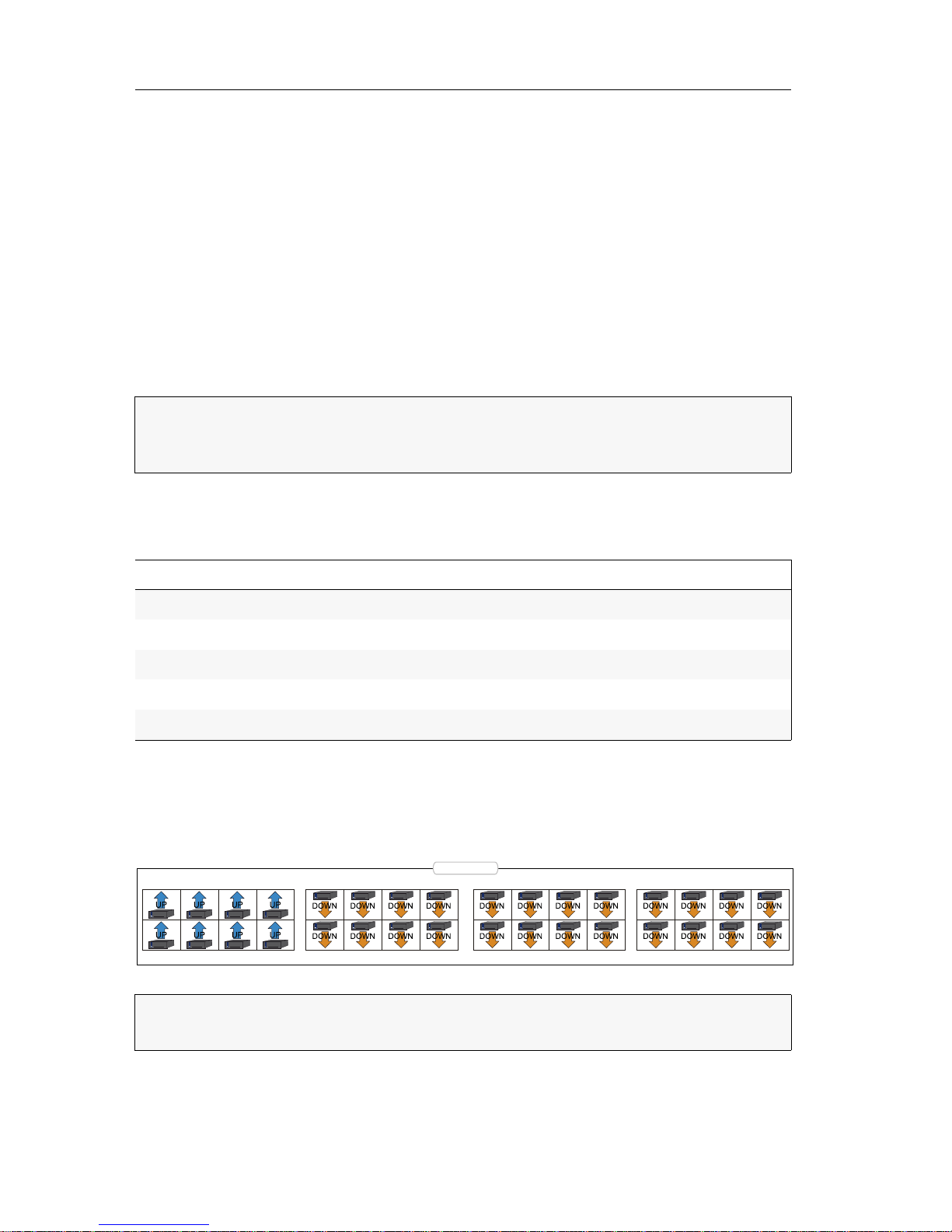
Der folgende Screenshot der Webapplikation Config Panel stellt die Standardaufteilung der Ports visuell dar.
An die Up-Ports können Sie die übergeordneten Matrixswitches anschließen. Die untergeordneten Matrixswitches einer Kaskade schließen Sie an die Down-Ports an.
HINWEIS:
Während die Ports bei Anschluss eines Arbeitsplatz- oder Target-
Moduls automatisch konfiguriert werden, ist im Falle der Kaskadierung der ein
-
gestellte Port-Modus zu beachten oder zu ändern.
Variante Up-Ports Down-Ports
ControlCenter-Compact-16C 1 bis 4 5 bis 16
ControlCenter-Compact-32C 1 bis 8 9 bis 32
ControlCenter-Compact-48C 1 bis 12 13 bis 48
ControlCenter-Compact-64C 1 bis 16 17 bis 64
ControlCenter-Compact-80C 1 bis 20 21 bis 80
WICHTIG:
Ausführliche Informationen zur Konfiguration der Dynamic Ports finden
Sie im Handbuch der Webapplikation Config
Panel.
10 12 14 16
1513119
246
8
753
1
18 20
22
24
17 19 21 23
26 28 30
32
31
29
2725
Dynamic Ports

Erweiterung des KVM-Matrixsystems
G&D ControlCenter-Compact · 17
Deutsch
Anschluss eines Slave-Zentralmoduls
So schließen Sie ein Slave-Zentralmodul an ein Mastergerät an:
1. Für jeden gleichzeitig auf das Slave-Zentralmodul aufschaltbaren Arbeitsplatz
konfigurieren Sie je einen Dynamic
Port als Up-Port.
2. Verbinden Sie die soeben konfigurierten Up-Ports des Slave-Gerätes mit Down-Ports
des Master-Gerätes.
Die Verbindung zwischen den Zentralmodulen wird mit Twisted-Pair-Kabel
der Kategorie 5e (oder höher) hergestellt.
3. Schließen Sie an das Slave-Zentralmodul wahlweise Target-Module oder weitere
Slave-Zentralmodule (max. 2 Kaskadenstufen) an.
4. Prüfen und ändern Sie ggf. den Kaskadenmodus des Master- und/oder des
Slave-Zentralmoduls
(s. Seite 17).
Festlegung des Kaskadenmodus des Zentralmoduls
Die einzelnen Zentralmodule erkennen selbständig, ob sie als Master- oder SlaveGerät innerhalb des KVM-Matrixsystems installiert wurden.
So ändern Sie den Kaskadenmodus eines Zentralmoduls:
1. Starten Sie das On-Screen-Display mit dem Hotkey Strg+Num (Standard).
2. Betätigen Sie die F11-Taste zum Aufruf des Configuration-Menüs.
3. Wählen Sie die Zeile System und betätigen Sie die Eingabetaste.
HINWEIS:
Die maximale Entfernung zwischen einem Mastergerät und dem
Slave-Zentralmodul beträgt 140 Meter.
HINWEIS:
Die unbeabsichtigte Änderung der Verkabelung der Geräte kann die
Umstellung des Betriebsmodus eines Zentralmoduls zur Folge haben.
Um dies zu verhindern, kann der Betriebsmodus jedes Zentralmoduls im On-
Screen-Display des jeweiligen Gerätes separat eingestellt werden.

Erweiterung des KVM-Matrixsystems
18 · G&D ControlCenter-Compact
4. Wählen Sie die Zeile Cascade mode und betätigen Sie die F8-Taste zur Auswahl
einer der aufgelisteten Optionen:
5. Betätigen Sie die F2-Taste zur Speicherung der durchgeführten Änderungen.
Auto:
Das Zentralmodul bestimmt selbstständig, ob er im Master- oder
Slave-Modus arbeitet.
Master:
In diesem Betriebsmodus können an Dynamic Ports, die für den
Anschluss von Target-Modulen konfiguriert sind, ausschließlich
Arbeitsplatzmodule angeschlossen werden.
Das Editieren der Bezeichnungen der angeschlossenen TargetModule ist möglich. Geänderte Bezeichnungen werden auf den
Slave-Geräten innerhalb der Kaskade automatisch aktualisiert.
Slave:
In diesem Betriebsmodus ist die Änderung der Namen der angeschlossenen Target-Module nicht möglich. Die Namen der TargetModule werden automatisch vom Master-Gerät bezogen.
Erweiterung der schaltbaren Signale
G&D ControlCenter-Compact · 19
Deutsch
Erweiterung der schaltbaren Signale
Sie können die schaltbaren Signale eines Rechners bzw. Arbeitsplatzes wahlweise
durch Kanal-Gruppierung oder durch Stacking erweitern.
Die verschiedenen Rechnermodule eines Rechners bzw. die verschiedenen Arbeits-
platzmodule eines Arbeitsplatzes werden im ControlCenter-Compact-System parallel
geschaltet.
Für die Erweiterung der schaltbaren Signale stehen zwei verschiedene Anschlusstechniken zur Verfügung:
Kanal-Gruppierung: In der Webapplikation Config Panel können Sie dem KVM-Kanal
eines Rechners oder Arbeitsplatzes zusätzlich max. sieben zusätzliche Videokanäle und
einen USB
2.0- bzw. RS 232-Kanal zuordnen.
Stacking: Im Stacking-Modus werden mehrere Matrixswitches parallel geschaltet.
Hierfür verbinden Sie mehrere Matrixswitches über die
Bus-Ports. Für jedes zusätzli-
che Arbeitsplatzmodul eines Arbeitsplatzes wird ein zusätzlicher Satelliten-Matrix-
switch angeschlossen.
Erweiterung durch Kanal-Gruppierung
In der Webapplikation können Sie dem KVM-Kanal eines Arbeitsplatzes max. sieben
zusätzliche Videokanäle und einen USB
2.0-/RS 232-Kanal zuordnen.
Dem KVM-Kanal eines Rechners können Sie ebenfalls max. sieben zusätzliche Videokanäle zuordnen. Hinzu kommt ein Pool aus vier Geräten für den USB 2.0-/RS 232Kanal.
BEISPIEL:
Für die Übertragung eines zweiten Videosignals und eines USB 2.0-
Signals eines Rechners schließen Sie zusätzlich zum Rechnermodul
DVI-CPU ein zwei-
tes Modul DVI-CPU (zweiter Videokanal) und ein Modul U2-CPU (USB 2.0/RS232) an
den Rechner an.
An den Arbeitsplatz, an welchem dieser Rechner aufgeschaltet wird, schließen Sie
neben dem Arbeitsplatzmodul
DVI-CON die Arbeitsplatzmodule DVI-CON-Video (zweiter
Videokanal) und
U2-CON (USB 2.0/RS232) an.
HINWEIS:
Nur in diesem Modus können Sie das USB-Signal über das Operation-
Menü des OSDs auf dem aktuell aufgeschalteten Rechner halten. Schalten Sie
nach dem Ausführen der Haltefunktion einen anderen Rechner auf, bleibt das USBSignal weiterhin auf dem zuvor aufgeschalteten Rechner.
Sobald Sie die Haltefunktion im Operation-Menü deaktivieren, wird das USB-Signal
des aktuell aufgeschalteten Rechners aufgeschaltet.
HINWEIS:
Bei den Kanalgruppierungen des Arbeitsplatzes repräsentiert ein
USB
2.0-/RS 232-Kanal ein einziges Gerät. Bei den Rechnern repräsentiert ein
solcher Kanal eine Gruppe aus bis zu vier Geräten.

Erweiterung der schaltbaren Signale
20 · G&D ControlCenter-Compact
Durch die Verwendung von Pools können Sie bis zu vier Benutzern gleichzeitig
Zugriff auf den USB
2.0-/RS 232-Kanal gewähren. Hierfür wählt der Matrixswitch bei
der Aufschaltung automatisch ein freies Gerät aus dem Pool.
Durch die Zuordnung mehrerer Kanäle zu einem Arbeitsplatz oder einem Rechner
erstellen Sie eine sogenannte Kanal-Gruppierung.
Erweiterung durch Port-Gruppierung
Eine neue Kanal-Gruppierung erstellen
So erstellen Sie eine neue Kanal-Gruppierung:
1. Klicken Sie im Strukturbaum auf KVM-Matrixsystem > [Name] > Arbeitsplatzmodule
bzw. Target-Module.
2. Klicken Sie mit der rechten Maustaste auf ein Arbeitsplatz- bzw. Rechnermodul,
das bisher keiner Kanal-Gruppierung zugeordnet ist.
3. Klicken Sie auf Kanal-Gruppierung im Kontextmenü.
Das ausgewählte Modul wird dem ersten KVM-Kanal zugeordnet und in der
Spalte
Zugeordnet angezeigt. In der linken Spalte (Nicht zugeordnet) werden die
Module des Matrixswitches aufgelistet, die Sie der neuen Kanal-Gruppierung
hinzufügen können.
4. Klicken Sie in der linken Spalte (Nicht zugeordnet) auf das hinzuzufügende Modul
und in der rechten Spalte (
Zugeordnet) auf den Kanal, dem Sie das Modul zuord-
nen möchten.
5. Klicken Sie auf (Pfeil rechts), um das Modul dem ausgewählten Kanal
zuzuordnen.
6. Wiederholen Sie die Punkte 4. und 5., um ein weiteres Modul der Kanal-Gruppie-
rung hinzuzufügen.
HINWEIS:
Arbeitsplatz- bzw. Rechnermodule, die Sie als Zusatzkanal einer
Kanal-Gruppierung zugeordnet haben, werden im OSD nicht aufgeführt.
HINWEIS:
Sie können dem KVM-Kanal eines Arbeitsplatzes max. sieben zusätzli-
che Videokanäle und ein USB 2.0- bzw. RS 232-Kanal zuordnen.
Dem KVM-Kanal eines Rechners können Sie ebenfalls max. sieben zusätzliche
Videokanäle zuordnen. Hinzu kommt ein
Pool aus vier Geräten für den USB 2.0-/
RS
232-Kanal.
HINWEIS:
Alle Kanäle einer Kanal-Gruppierung werden gleichzeitig geschaltet!
HINWEIS:
Zur nachträglichen Änderung der Reihenfolge bereits hinzugefügter
Kanäle markieren Sie einen Kanal und klicken auf
(Pfeil hoch) oder
(Pfeil runter). Der ausgewählte Kanal wird nach oben bzw. unten verschoben.

Erweiterung der schaltbaren Signale
G&D ControlCenter-Compact · 21
Deutsch
7. Klicken Sie auf OK zu Speicherung der neuen Kanal-Gruppierung.
Module einer Kanal-Gruppierung hinzufügen oder entfernen
So fügen Sie Module einer Kanal-Gruppierung hinzu oder löschen die
bestehende Zuordnung eines Moduls:
1. Klicken Sie im Strukturbaum auf KVM-Matrixsystem > [Name] > Arbeitsplatzmodule
bzw. Target-Module.
2. Klicken Sie mit der rechten Maustaste auf ein Arbeitsplatz- bzw. Rechnermodul,
das bereits der Kanal-Gruppierung zugeordnet ist, der Sie ein weiteres Modul
zuordnen möchten oder aus der Sie ein Modul entfernen möchten.
3. Klicken Sie auf Kanal-Gruppierung im Kontextmenü.
Die derzeitige Konfiguration wird angezeigt. In der linken Spalte (Nicht zugeordnet)
werden die Module des Matrixswitches aufgelistet, die Sie der Kanal-Gruppie
-
rung hinzufügen können.
4. Fügen Sie der Kanal-Gruppierung weitere Module hinzu oder entfernen Sie
Module aus der Konfiguration:
HINWEIS:
Die in der Kanal-Gruppierung enthaltenen Arbeitsplatz- oder Rechnermodule werden in der Auflistung der Module mit einem Plus-Zeichen hinter
dem Namen angezeigt.
Klicken Sie auf das Symbol, um die Auflistung der Module einzusehen.
HINWEIS:
Sie können dem KVM-Kanal eines Arbeitsplatzes max. sieben zusätzliche Videokanäle und einen USB 2.0- bzw. RS 232-Kanal zuordnen.
Dem KVM-Kanal eines Rechners können Sie ebenfalls max. sieben zusätzliche
Videokanäle zuordnen. Hinzu kommt ein
Pool aus vier Geräten für den USB 2.0-/
RS
232-Kanal.
Ein Modul hinzufügen:
Klicken Sie in der linken Spalte (Nicht zugeordnet) auf
das hinzuzufügende Modul und in der rechten
Spalte (
Zugeordnet) auf den Kanal, dem Sie das
Modul zuordnen möchten.
Klicken Sie auf (Pfeil rechts), um das Modul dem
ausgewählten Kanal zuzuordnen.
Ein Modul entfernen:
Klicken Sie in der rechten Spalte (Zugeordnet) auf das
Modul, das Sie aus der Kanal-Gruppierung entfernen
möchten.
Klicken Sie auf (Pfeil links), um die Zuordnung
des Moduls zu löschen.

Erweiterung der schaltbaren Signale
22 · G&D ControlCenter-Compact
5. Klicken Sie auf OK zu Speicherung der neuen Kanal-Gruppierung.
Eine Kanal-Gruppierung löschen
So löschen Sie eine Kanal-Gruppierung:
1. Klicken Sie im Strukturbaum auf KVM-Matrixsystem > [Name] > Arbeitsplatzmodule
bzw. Target-Module.
2. Klicken Sie mit der rechten Maustaste auf ein Arbeitsplatz- bzw. Rechnermodul,
das bereits der Kanal-Gruppierung zugeordnet ist, die Sie löschen möchten.
3. Klicken Sie auf Kanal-Gruppierung im Kontextmenü.
Die derzeitige Konfiguration wird angezeigt.
4. Klicken Sie in der rechten Spalte (Zugeordnet) auf ein Modul, das einem der KVMKanäle 2 bis 8 bzw. dem USB/RS232-Kanal zugeordnet ist.
Klicken Sie auf (Pfeil links), um die Zuordnung des Moduls zu löschen.
5. Wiederholen Sie ggf. Punkt 4., um die Zuordnungen weiterer Module zu
löschen.
6. Sobald nur noch dem KVM-Kanal 1 ein Modul zugeordnet ist, klicken Sie auf OK.
Die Kanal-Gruppierung wird gelöscht.
HINWEIS:
Die in der Kanal-Gruppierung enthaltenen Arbeitsplatz- oder Rechnermodule werden in der Auflistung der Module mit einem Plus-Zeichen hinter
dem Namen angezeigt.
Klicken Sie auf das Symbol, um die Auflistung der Module einzusehen.
HINWEIS:
Die Webapplikation löscht eine Kanal-Gruppierung, sobald außer
dem KVM-Kanal 1 keine weiteren Kanäle mehr zugeordnet sind.
Erweiterung der schaltbaren Signale
G&D ControlCenter-Compact · 23
Deutsch
Erweiterung durch Stacking
Im Stacking-Modus werden mehrere Matrixswitches parallel geschaltet.
Hierfür verbinden Sie die Matrixswitches über die Bus-Ports und vergeben den
Matrixswitches fortlaufende Bus-Adressen.
Jeder Stack-Matrixswitch besteht aus einem Matrixswitch, der den KVM Main Channel
bereitstellt. Ergänzt wird er durch maximal 9 Satelliten-Matrixswitches. Die Satelliten können wahlweise als Video Channel oder als USB/RS232 Channel genutzt werden.
Bei Verwendung von drei Matrixswitches können so beispielsweise pro Arbeitsplatz
zusätzlich zu den Standard-Signalen eines Arbeitsplatzmoduls (Videosignal und
Tastatur- sowie Maussignale) ein zweites Videosignal und USB 2.0-Signale übertra
-
gen werden:
Anschluss eines Stack-Matrixswitches
Als Stack-Matrixswitch wird ein Matrixswitch bezeichnet, über den zusätzliche
Signale eines Rechners bzw. Arbeitsplatzes übertragen werden.
Ein Stack-Matrixswitch wird nicht vom Anwender, sondern vom Primary-Matrixswitch geschaltet. Schaltet der Anwender am Primary-Matrixswitch einen Port auf,
so wird dieser Port auch auf den Stack-Matrixswitches aufgeschaltet.
Sie können maximal zehn Matrixswitches (1 × Primary, 9 × Satelliten) zu einer
Stack-Kaskade verbinden.
WICHTIG:
Innerhalb eines Kanals können Sie ausschließlich kompatible Target-
und Arbeitsplatzmodule einsetzen:
Video Follower Channel: Arbeitsplatz- und Targetmodule der DVI-CON bzw.
DVI-CPU-Familie
USB/RS232 Main Channel: Arbeitsplatz- und Targetmodule der U2-CON bzw.
U2-CPU-Familie
HINWEIS:
Schließen Sie die Arbeitsplatzmodule eines Arbeitsplatzes an die glei-
chen Portnummern der verschiedenen Kanäle an.
Gleiches gilt auch für die verschiedenen Target-Module eines Rechners.
Matrixswitch Arbeitsplatzmodul Signale
Matrixswitch 1 (Primary) DVI-CON DVI, PS/2, USB
Matrixswitch 2 (Satellite 1) DVI-CON-Video DVI
Matrixswitch 3 (Satellite 2) U2-R-CON USB 2.0, RS 232

Erweiterung der schaltbaren Signale
24 · G&D ControlCenter-Compact
Bus-Adresse eines Matrixswitches einstellen
Der Primary-Matrixswitch schaltet automatisch die Stack-Matrixswitches auf den
gleichen Port, den der Anwender am Primary-Matrixswitch aufschaltet.
Um dies zu gewährleisten, ist die korrekte Einstellung der Bus-Adresse in den einzelnen Matrixswitches erforderlich.
So ändern Sie die Bus-Adresse eines Matrixswitches:
1. Klicken Sie im Strukturbaum auf KVM Matrixsysteme > [Name] > Matrixswitches.
2. Klicken Sie mit der rechten Maustaste auf den Matrixswitch und anschließend
auf
Konfiguration im Kontextmenü.
3. Klicken Sie auf den Reiter Allgemein.
4. Wählen Sie im Feld Bus-Adresse zwischen folgenden Optionen:
5. Klicken Sie auf OK, um den Dialog zu verlassen.
primary:
Das Zentralmodul wird vom Anwender bedient.
Es schaltet automatisch die Satelliten-Matrixswitches.
satellite 1 … 9:
Vergeben Sie diese Adressen fortlaufend für die einzelnen
Stacking-Matrixswitches.

Statusanzeigen
G&D ControlCenter-Compact · 25
Deutsch
Statusanzeigen
LEDs an der Frontseite
Die LEDs an der Frontseite des Zentralmoduls geben Ihnen die Möglichkeit, den
Betriebsstatus des Systems jederzeit zu kontrollieren:
Bereich LED Status Bedeutung
Power Red. an Das Netzteil ist eingeschaltet und liefert die
erforderliche Spannung.
aus Das Netzteil ist ausgeschaltet oder die Verbindung mit
dem Stromnetz nicht hergestellt.
Main an Das Netzteil ist eingeschaltet und liefert die
erforderliche Spannung.
aus Das Netzteil ist ausgeschaltet oder die Verbindung mit
dem Stromnetz nicht hergestellt.
Device Port-
function
aus An den Dynamic Ports wird der Status signalisiert.
an An den Dynamic Ports wird der Port-Modus signalisiert.
Status blinkt Das Zentralmodul ist einsatzbereit.
an Das Zentralmodul wird initialisiert.
Fail an Das Gerät ist nicht betriebsbereit.
aus Das Gerät ist betriebsbereit oder ausgeschaltet.
Ident. an LED zur Identifizierung des Gerätes in der Webapplikation
aktiviert.
aus LED zur Identifizierung des Gerätes in der Webapplikation
deaktiviert.

Statusanzeigen
26 · G&D ControlCenter-Compact
LEDs an der Rückseite
Auf der Rückseite des Zentralmoduls befinden sich an jeder RJ45-Schnittstelle
zusätzliche Status-LEDs. Diese LEDs haben folgende Funktion:
Schnittstelle LED Status Bedeutung
Network gelb an Verbindung aktiv
grün blinkt Aktivität auf der Netzwerkschnittstelle festgestellt
Dynamic Port gelb an Status-Modus:
Ein Benutzer ist am Arbeitsplatzmodul eingeloggt
bzw. auf das Targetmodul aufgeschaltet.
Port-Modus:
Der Port ist für den Anschluss eines Arbeitsplatzmoduls
konfiguriert.
aus Der Port ist nicht belegt.
grün an Status-Modus:
Verbindung zum Arbeitsplatz- bzw. Targetmodul
hergestellt.
Port-Modus:
Der Port ist für den Anschluss eines Target-Moduls konfiguriert.
aus Es konnte keine Verbindung zum Arbeitsplatz- bzw.
Targetmodul hergestellt werden.

Technische Daten
G&D ControlCenter-Compact · 27
Deutsch
Technische Daten
Allgemeine Eigenschaften der Serie
Spezifische Eigenschaften der Geräte
CONTROLCENTER-COMPACT-SERIE
Schnittstellen Dynamic Ports: siehe spezifische Eigenschaften
Die Ports sind wahlweise für den Anschluss eines Arbeitsplatz- bzw. eines
Target-Moduls verwendbar.
Netzwerkanbindung: 2 × RJ45-Buchse
Direktverbindung zu einem
weiteren Zentralmodul:
2 × RJ45-Buchse
Powerswitch (RS 232): 1 × RJ11-Buchse
RS 485: 1 × RJ45-Buchse
reserviert für zukünftige Funktionen
USB 2.0 2 × USB-A-Buchse
reserviert für zukünftige Funktionen
USB 3.0 1 × USB-A-Buchse
reserviert für zukünftige Funktionen
Hauptstromversorgung
Typ: internes Netzteil
Anschluss: 1 × Kaltgerätestecker (IEC-320 C14)
Stromaufnahme: siehe spezifische Eigenschaften
Redundante
Stromversorgung
Typ: internes Netzteil
Anschluss: 1 × Kaltgerätestecker (IEC-320 C14)
Stromaufnahme: siehe spezifische Eigenschaften
Gehäuse Material: Aluminium eloxiert
Dimensionen (B × H × T): siehe spezifische Eigenschaften
Einsatzumgebung Temperatur: +5 bis +40 °C
Luftfeuchte: < 80%, nicht kondensierend
Konformität CE, RoHs
CONTROLCENTER-COMPACT-16C
Schnittstellen Dynamic Ports: 16 × RJ45-Buchse
Hauptstrom-
versorgung
Stromaufnahme: 100-240V/60-50Hz, 0.6-0.4A
Redundante
Stromversorgung
Stromaufnahme: 100-240V/60-50Hz, 0.6-0.4A
Gehäuse Dimensionen (B × H × T): 435 × 44 × 211 mm

Technische Daten
28 · G&D ControlCenter-Compact
CONTROLCENTER-COMPACT-32C
Schnittstellen Dynamic Ports: 32 × RJ45-Buchse
Hauptstrom-
versorgung
Stromaufnahme: 100-240V/60-50Hz, 0.7-0.4A
Redundante
Stromversorgung
Stromaufnahme: 100-240V/60-50Hz, 0.7-0.4A
Gehäuse Dimensionen (B × H × T): 435 × 44 × 211 mm
CONTROLCENTER-COMPACT-48C
Schnittstellen Dynamic Ports: 48 × RJ45-Buchse
Hauptstrom-
versorgung
Stromaufnahme: 100-240V/60-50Hz, 0.8-0.4A
Redundante
Stromversorgung
Stromaufnahme: 100-240V/60-50Hz, 0.8-0.4A
Gehäuse Dimensionen (B × H × T): 435 × 88 × 211 mm
CONTROLCENTER-COMPACT-64C
Schnittstellen Dynamic Ports: 64 × RJ45-Buchse
Hauptstrom-
versorgung
Stromaufnahme: 100-240V/60-50Hz, 0.8-0.4A
Redundante
Stromversorgung
Stromaufnahme: 100-240V/60-50Hz, 0.8-0.4A
Gehäuse Dimensionen (B × H × T): 435 × 88 × 211 mm
CONTROLCENTER-COMPACT-80C
Schnittstellen Dynamic Ports: 80 × RJ45-Buchse
Hauptstrom-
versorgung
Stromaufnahme: 100-240V/60-50Hz, 0.9-0.4A
Redundante
Stromversorgung
Stromaufnahme: 100-240V/60-50Hz, 0.9-0.4A
Gehäuse Dimensionen (B × H × T): 435 × 88 × 211 mm

Deutsch

i · G&D ControlCenter-Compact
About this manual
This manual has been carefully compiled and examined to the state-of-the-art.
G&D neither explicitly nor implicitly takes guarantee or responsibility for the quality, efficiency and marketability of the product when used for a certain purpose that
differs from the scope of service covered by this manual.
For damages which directly or indirectly result from the use of this manual as well
as for incidental damages or consequential damages, G&D is liable only in cases of
intent or gross negligence.
Caveat Emptor
G&D will not provide warranty for devices that:
Are not used as intended.
Are repaired or modified by unauthorized personnel.
Show severe external damages that was not reported on the receipt of goods.
Have been damaged by non G&D accessories.
G&D will not be liable for any consequential damages that could occur from using
the products.
Proof of trademark
All product and company names mentioned in this manual, and other documents
you have received alongside your G&D product, are trademarks or registered trade
-
marks of the holder of rights.
© Guntermann & Drunck GmbH 2016. All rights reserved.
Version 1.00 – 06/10/2016
Firmware: 1.0.000
Guntermann & Drunck GmbH
Dortmunder Str. 4a
57234 Wilnsdorf
Germany
Phone +49 2739 8901-100
Fax +49 2739 8901-120
http://www.GDsys.de
sales@GDsys.de

Table of contents
G&D ControlCenter-Compact · ii
English
Contents
Safety instructions ............................................................................................ 1
The »ControlCenter-Compact« KVM matrix system ........................................ 2
Expanding a KVM matrix system ...................................................................... 2
The central module ........................................................................................... 3
Package contents .............................................................................................. 3
Required accessories ......................................................................................... 3
Installation ....................................................................................................... 4
Power supply .................................................................................................... 4
Installing and connecting user modules .............................................................. 5
Connecting console devices to user modules ................................................. 5
Connecting user modules to the central module ............................................ 5
Installing and connecting target modules ............................................................ 6
Connecting target computers to target modules ............................................. 6
Connecting target modules to the central module .......................................... 6
Network interfaces ............................................................................................ 7
Recommended twisted pair cables .................................................................... 8
Initial configuration of network settings .......................................................... 9
Configuring network ports ................................................................................. 9
Configuring the «global» network settings ........................................................ 10
Reset button ................................................................................................... 11
Resetting the default settings ............................................................................ 11
Disabling the netfilter rules temporarily ............................................................ 12
Configuring dynamic ports ............................................................................. 13
Automatic port mode ...................................................................................... 13
Special features for cascading a matrix switch ............................................. 13
Compatibility mode ......................................................................................... 14
Expanding the KVM matrix system by cascading ........................................... 15
Cascading (default) .................................................................................... 15
KVM Matrix-Grid™ (subject to a charge) ................................................... 15
Cascading a matrix switch ............................................................................... 16
Configuration and highlighting of port assignment ........................................... 16
Connecting a slave central module ................................................................... 17
Defining the cascade mode of the central module ............................................. 17
Expanding switchable signals ......................................................................... 19
Expanding the system through channel grouping .............................................. 19
Expanding through port grouping .................................................................... 20
Creating a new channel group .................................................................... 20
Adding or deleting modules from a channel group ...................................... 21
Deleting a channel group ........................................................................... 22

Table of contents
iii · G&D ControlCenter-Compact
Expanding the system through stacking ............................................................ 23
Connecting a stack matrix switch ................................................................ 23
Adjusting the bus address of matrix switches ............................................... 24
Status displays ................................................................................................ 25
Technical data ................................................................................................ 27
General features of the series ............................................................................ 27
Specific features of the devices .......................................................................... 27

Safety instructions
G&D ControlCenter-Compact · 1
English
Safety instructions
Please read the following safety instructions carefully before you start operating the
G&D product. The instructions well help in avoiding damages to the product and in
preventing possible injuries.
Keep this manual handy for all persons who will be using this product.
Follow all warnings or operating instructions which are on the device or stated in
this user manual.
, Beware of electric shocks
To avoid the risk of electric shock, do not open the device or remove the covers.
If service is required, please contact our technicians.
, Disconnect the main power plug or the power supply before installation
Before installation, ensure that the device has been disconnected from the power
source. Disconnect the main power plug or the power supply of the device.
, Ensure constant access to the power plugs
During the installation of the devices, ensure that the power plugs remain accessible.
, Do not cover the ventilation openings
Ventilation openings prevent the device from overheating. Do not cover them.
! Avoid tripping hazards
Avoid tripping hazards while laying cables.
, Only use a grounded voltage source
Operate this device by using a grounded voltage source.
, Use only the provided G&D power pack
Operate this device with the provided G&D power pack or with the power pack
listed in the manual.
! Operate the device only in designated areas.
The devices are designed for indoor use. Avoid exposure to extreme cold, heat
or humidity.

The »ControlCenter-Compact« KVM matrix system
2 · G&D ControlCenter-Compact
The »ControlCenter-Compact«
KVM
matrix system
KVM matrix systems of the ControlCenter-Compact series consist of at least one central module, one user module and one target module.
The central module of the ControlCenter-Compact series is the central device of the
KVM matrix system. Both target and user modules are connected to the central
module.
You can use the KVM matrix system to access a target module with a user module.
By accessing the computer connected to the target module, the video image is displayed at the console monitor. You can now operate the accessed computer with
console keyboard and console mouse.
The ControlCenter-Compact series includes the following variants:
Use the dynamic ports to connect either user modules or target modules.
Expanding a KVM matrix system
If the number of ports of a matrix switch is not sufficient for the desired purpose,
you can combine multiple matrix switches.
For this, we provide the technologies Cascading (default) and KVM Matrix-Grid™ (subject to a charge).
Information about these technologies is given in the chapter Expanding the KVM
matrix system by cascading on page 15.
Variant Dynamic ports to connect modules
ControlCenter-Compact-16C 16 × RJ45 socket (CAT)
ControlCenter-Compact-32C 32 × RJ45 socket (CAT)
ControlCenter-Compact-48C 48 × RJ45 socket (CAT)
ControlCenter-Compact-64C 64 × RJ45 socket (CAT)
ControlCenter-Compact-80C 80 × RJ45 socket (CAT)

The central module
G&D ControlCenter-Compact · 3
English
The central module
The central module ControlCenter-Compact is the central device within a KVM matrix
system. The target and user modules are connected to the central module
.
The central module controls the access of a user module to a target module.
Package contents
1 × ControlCenter-Compact matrix switch
2 × power cable (PowerCable-2 Standard)
1 × rack mount set
1 × service cable (USB-Service-2)
1 × manual »Installation Guide«
1 × manual set »Target modules and user modules«
default variants
devices with integrated USB
DP-HR variants
DP-HR-U variants
1 × manual »Operation & Configuration«
1 × manual »Config Panel web application«
Required accessories
One or two category 5e (or better) twisted pair cables to connect the central module
to one or two local networks.
Installation
4 · G&D ControlCenter-Compact
Installation
The following pages describe the installation of the devices of the KVM system.
Power supply
Main Power: Plug one of the supplied power cable in this interface. Connect the
power cable with a power outlet and turn the power button on.
Red. Power: If required, plug one of the supplied power cable in this interface to
establish a redundant power supply. Connect the power cable with a power outlet of
another power circuit and turn the power button on.
NOTE:
The following drawings refer to the ControlCenter-Compact-32C. The different
variants vary in the number of dynamic ports to connect user modules and target
modules.
NOTE:
When choosing a place for the device, please ensure to comply with the
ambient temperature limit
(see Technical data on page 27) close to the device. The
ambient temperature limit must not be influenced by other devices.
18 20
22
24
17 19 21 23
26 28 30
32
31
29
2725
Power
Red.
Main
Bus Out
Bus In
Status
Ident.
Fail
Portfunction
Main Power
Red. Power
Installation
G&D ControlCenter-Compact · 5
English
Installing and connecting user modules
Connecting console devices to user modules
Connect the console devices to the different user modules.
The steps required to connect these devices are described in the manual supplied
with the modules:
Connecting user modules to the central module
Connect the Transmission interfaces of each individual user module to one of the
dynamic ports of the central module.
Use a category 5e (or better) twisted-pair cabling for connecting the devices.
IMPORTANT:
You can place user modules up to 140 metres away from the central
module.
Manual Order number Download link
Standard variants A9100221 http://gdsys.de/A9100221
Devices with integrated USB A9100249 http://gdsys.de/A9100249
DP-HR variants A9100259 http://gdsys.de/A9100259
DP-HR-U variants A9100260 http://gdsys.de/A9100260
10 12 14 16
1513119
246
8
753
1
18 20
22
24
17 19 21 23
26 28 30
32
31
29
2725
Dynamic Ports

Installation
6 · G&D ControlCenter-Compact
Installing and connecting target modules
Connecting target computers to target modules
Connect the target computer to the different target modules.
The steps required to connect these devices are described in the manual supplied
with the modules
:
Connecting target modules to the central module
Connect the Trans. interfaces of each individual target module to one of the
dynamic ports of the central module.
Use a category 5e (or better) twisted-pair cabling for connecting the devices.
IMPORTANT:
You can place target modules up to 140 metres away from the central
module.
Manual Order number Download link
Standard variants A9100221 http://gdsys.de/A9100221
Devices with integrated USB A9100249 http://gdsys.de/A9100249
DP-HR variants A9100259 http://gdsys.de/A9100259
DP-HR-U variants A9100260 http://gdsys.de/A9100260
IMPORTANT:
The DVI-CPU-UC target module provides two Trans. interfaces. Only
connect one Trans. interface of the target module to the matrix switch.
10 12 14 16
1513119
246
8
753
1
18 20
22
24
17 19 21 23
26 28 30
32
31
29
2725
Dynamic Ports
Installation
G&D ControlCenter-Compact · 7
English
Network interfaces
Network A: If required, plug in a category 5e (or better) twisted-pair cable, which is
available as accessory.
Connect the other end of the cable to a network interface of the local network.
Network B: If required, plug in a category 5e (or better) twisted-pair cable, which is
available as accessory.
Connect the other end of the cable to a network interface of the local network.
NOTE:
You need to connect the central module to one or two local networks to
configure the central module via Config
Panel web application and use the
enhanced network functionalities (for example authentication against directory
services, time sync via NTP server, netfilter or syslog).
IMPORTANT:
If you change the configuration of the Dynamic Ports in the web application, or if you enable the signalling of the Dynamic Ports modes, end the connection to the web application and remove the twisted-pair cable from the network port
at the central module.
Network A
Network B
10 12 14 16
1513119
246
8
753
1
18 20
22
24
17 19 21 23
26 28
29
2725
Dynamic Ports

Recommended twisted pair cables
8 · G&D ControlCenter-Compact
Recommended twisted pair cables
The transmission of all signals of the ControlCenter-Compact system is carried out
through one twisted pair cable (category 5e or better).
The data transmission is reliable over a distance of at least 80 metres using a regular
standard twisted pair cable (category 5e or better).
The distance that can actually be bridged depends on the quality of the applied
cable. High-quality S-STP cables with an AWG22 wire gauge coding can bridge a
distance of up to 140 metres.
Patch cables with an AWG26 wire gauge coding can only bridge a maximum of 80
metres.
In order to ensure a reliable operation even in environments with interferences,
installation cables with at least AWG24 coding have to be used for lengths over 80
metres:
The following cables achieved the best results during test operation:
NOTE:
It is permitted to connect several segments of a cable connection with patch
panels and connection ports. It is, however, not permitted to connect active com
-
ponents such as network switches, hubs or repeaters are not permitted.
Wire gauge Cable type Category Recommendation
AWG22 Installation 5e, 6 or 7 up to 140 m
AWG24 Installation 5e, 6 or 7 up to 120 m
AWG26/27 Patch cable 5e, 6 or 7 up 80 m
NOTE:
The lengths that are mentioned in the table above must be interpreted as the
sum of all segments between the devices.
up to 80 meters: Dätwyler uninet® 7702 flex
Patch cable
up to 100 meters: Dätwyler uninet® 5502 AWG24 S-STP
Installationcable with sockets
up to 140 meters: Kerpen MegaLine® G12-150 S/F AWG22
Installation cable with sockets
Dätwyler uninet® 7702 AWG 22
Installation cables with sockets
Initial configuration of network settings
G&D ControlCenter-Compact · 9
English
Initial configuration of network settings
Accessing the Config Panel web application and using the expanded network functions
requires you to configure the network settings of the matrix switch.
You can configure the network settings by using one of the new consoles.
Configuring network ports
A central module, which is integrated into the network, can only be addressed after
the network ports are configured.
How to configure the settings of a network port:
1. After the console is switched on, the matrix switch asks you to log in. Enter the
following data to the login box:
2. Press Enter to login and open the on-screen display.
3. Press F11 to call the Configuration menu.
4. Select the Network entry and press Enter.
5. Select the Settings entry and press Enter.
6. Enter the following data in the Interface A (interface Network A) or Interface B (inter-
face Network B) section:
NOTE:
In the defaults, the following settings are pre-selected:
IP address of network interface A: 192.168.0.1
IP address of network interface B: address obtained using DHCP
global network settings: settings obtained using DHCP
ADVICE:
Use the information menu to retrieve the IP addresses of the network inter-
faces A and B.
After opening the on-screen display, press F12, select the line Hardware information.
and press
Enter.
Username:
Enter the default username Admin.
Password:
Enter the default password 4658.

Initial configuration of network settings
10 · G&D ControlCenter-Compact
7. Press F2 to save your settings.
Configuring the «global» network settings
In complex networks, the global network settings ensure that the matrix switch is
available from all sub networks.
How to configure the global network settings:
1. Press Ctrl+Num (default) to open the on-screen display of the KVM matrix system.
2. Press F11 to call the Configuration menu.
3. Select the Network entry and press Enter.
4. Select the Settings entry and press Enter.
5. Enter the following data in the Main Network paragraph:
6. Press F2 to save your settings.
Operational
mode:
Press F8 to select the operating mode of the interface
Network A or Network B:
Off: switches off network interface.
Static: uses static settings.
DHCP: obtains the settings from a DHCP server.
IP address:
Enter the interface IP address.
This setting is auto obtained in the DHCP operating mode.
Netmask:
Enter the network netmask.
This setting is auto obtained in the DHCP operating mode.
Connection type:
Press F8 to define if the network port and its communication
partner are to negotiate the connection type automatically
(
Auto) or select one of the listed types.
Global preferences
Select the operating mode by pressing F8:
Static: uses static settings.
DHCP: auto obtains the settings described below from a
DHCP server.
Hostname:
Enter the matrix switch hostname.
Domain:
Enter the domain the matrix switch is to belong to.
Gateway:
Enter the gateway IP address.
DNS Server 1:
Enter the DNS server IP address.
DNS Server 2:
Enter the IP address of another DNS server (option).

Reset button
G&D ControlCenter-Compact · 11
English
Reset button
The Reset button is placed between the Power LEDs and the Identification LED on the
front panel of the central module.
This button allows you to reset the default settings and disable the netfilter rules.
Resetting the default settings
Pressing and holding the button during the booting process resets the default settings
of the central module.
How to reset the default settings of the central module:
1. Turn off both power packs of the central module.
2. Press and hold the Reset button on the front panel of the device.
3. Keep the button pressed and turn the device on.
4. Release the button when the green Status-LED starts blinking.
NOTE:
To prevent you from pressing the button by accident, you are required to
use a thin, pointed object for pressing the button.
NOTE:
After the function has been carried out, the default settings of the central
module do apply again. However, the purchased premium functions remain unal
-
tered.
NOTE:
You can also use the Config Panel web application to reset the default settings.

Reset button
12 · G&D ControlCenter-Compact
Disabling the netfilter rules temporarily
In the default status of the central module, all network computers have access to the
extender’s IP address (open system access).
The web application enables you to create netfilter rules to control the access to the
device. If a netfilter rule is created, the open access to the system is disabled and all
incoming data packets are compared to the netfilter rules.
If the currently adjusted netfilter rules prevent access to the Config Panel web application, they can be can temporarily disabled in order to be edited.
How to disable the netfilter rules temporarily:
1. If necessary, switch on the central module and wait until the device is ready for
operation.
2. Press and hold the Reset button on the front panel of the device for 5 seconds.
3. Use the Config Panel web application to edit the netfilter rules that are stored in
the appliance and, afterwards, save these rules.
IMPORTANT:
Now, the open system access is enabled.
IMPORTANT:
The former settings are reactivated if no new netfilter rules are
created within 15 minutes.

Configuring dynamic ports
G&D ControlCenter-Compact · 13
English
Configuring dynamic ports
The different device variants of the ControlCenter-Compact series provide up to 80
dynamic ports for the connection of user modules and target modules.
Automatic port mode
By default, the matrix switch detects the user modules (CON) or target modules (CPU)
connected to the ports and auto-configures the ports.
Special features for cascading a matrix switch
By cascading a matrix switch, you can increase the number of connectable target
computers. For this, connect further matrix switches to the configured ports:
Connect master matrix switches to up ports.
Connect slave matrix switches to down ports.
By deault, the ports of the different variants of the ControlCenter-Compact series are
configured to connect both master and slave matrix switches:
IMPORTANT:
The manual of the web application Config Panel provides detailed
information about the configuration of dynamic ports.
NOTE:
The number of ports depends on ControlCenter-Compact variant.
the following paragraphs describe the configuration of the 32 ports of a Control-
Center-Compact-32C.
IMPORTANT:
Mind or change the port mode of a cascade.
10 12 14 16
1513119
246
8
753
1
18 20
22
24
17 19 21 23
26 28 30
32
31
29
2725
Dynamic Ports
Configuring dynamic ports
14 · G&D ControlCenter-Compact
Compatibility mode
Activating the compatibility mode of matrix switches belonging to the ControlCenter-Compact series is required only if you want to integrate a matrix switch of the
DVICenter series, whose ports are operated in compatibility mode, into the cascade.
Variant Up ports Down ports
ControlCenter-Compact-16C 1 to 4 5 to 16
ControlCenter-Compact-32C 1 to 8 9 to 32
ControlCenter-Compact-48C 1 to 12 13 to 48
ControlCenter-Compact-64C 1 to 16 17 to 64
ControlCenter-Compact-80C 1 to 20 21 to 80
NOTE:
For matrix switches of the DVICenter series, the compatibility mode has
been automatically activated after an update to firmware version 1.4 or later if the
default port assignments had been manually changed to the
CON or CPU mode prior
to the update.
ADVICE:
Update the firmware version of all matrix switches belonging to a cascade to the latest version. Now deactivate the compatibility mode for all matrix
switches.

Expanding the KVM matrix system by cascading
G&D ControlCenter-Compact · 15
English
Expanding the KVM matrix system by
cascading
If the number of ports of a matrix switch is not sufficient for the desired purpose,
you can combine multiple matrix switches. For this, we provide the following tech
-
nologies:
Cascading (default)
To establish a cascade, connect a slave matrix switch to the master matrix switch.
Connect either several target computers or further slave matrix switches (max. two
cascade levels) to the slave matrix switch.
Due to the top-down structure of the cascade, user modules can access only target
computers connected to the same matrix switch as the user module or to a matrix
switch that is subordinate in the tree structure (cascaded)
More information about Cascading is given on the following pages.
KVM Matrix-Grid™ (subject to a charge)
The premium function KVM Matrix-Grid™ allows you to use each matrix port within
the matrix grid to connect either user modules, target modules or grid lines (see
below). While a cascade increases only the number of connectable target computers,
the matrix grid allows the universal expansion of existing KVM installations.
Additionally, the function removes the limitations of the top-down structure within
cascades and enables bidirectional communication between user modules and target
modules connected to different matrix switches. This allows you to combine several
digital matrix switches to one large network of matrix switches. User modules and
target computers can be connected to any matrix switch included in the matrix grid.
All user modules can access any target computer (independently of the matrix
switch to which they are connected).
The system takes over the (bidirectional) routing of KVM signals and chooses the
ideal signal path between modules.
More information about the KVM Matrix-Grid™ is given in the separate addendum.

Expanding the KVM matrix system by cascading
16 · G&D ControlCenter-Compact
Cascading a matrix switch
Cascading allows you to increase the number of target computers to be connected.
In a cascade, a slave central module is connected to the dynamic ports of a master
central module. These ports must be configured as ports for the connection of target
modules.
You can connect either target modules or further slave central modules (up to 2 cascade levels) to the slave central module.
Configuration and highlighting of port assignment
By default, the matrix switch auto-detects the modules connected to the ports and
configures the ports accordingly.
By default, the ports of the different variants of the ControlCenter-Compact series are
configured to connect both master and slave matrix switches:
The following screenshot of the web application Config Panel shows the default port
assignment.
Connect master matrix switches to up ports and slave matrix switches of a cascade to
down ports.
NOTE:
When connecting a user module or a target module, the ports are auto-con-
figured. In case of a cascade, note or change the port mode.
Variant Up ports Down ports
ControlCenter-Compact-16C 1 to 4 5 to 16
ControlCenter-Compact-32C 1 to 8 9 to 32
ControlCenter-Compact-48C 1 to 12 13 to 48
ControlCenter-Compact-64C 1 to 16 17 to 64
ControlCenter-Compact-80C 1 to 20 21 to 80
IMPORTANT:
Detailed information about the configuration of dynamic ports is given
in the manual of the web application Config
Panel.
10 12 14 16
1513119
246
8
753
1
18 20
22
24
17 19 21 23
26 28 30
32
31
29
2725
Dynamic Ports

Expanding the KVM matrix system by cascading
G&D ControlCenter-Compact · 17
English
Connecting a slave central module
How to connect a slave central module to a master device:
1. Configure the same number of dynamic ports as up ports as consoles that you
want to allow to simultaneously access the slave central module.
2. Now connect the configured up ports of the slave device to the down ports of the
master device.
Use regular CAT5 twisted pair cables to connect the central modules.
3. Connect the target modules or other slave central modules to the slave central
module (up to 2 cascade levels).
4. Check and, if necessary, change the cascade mode of the master and/or the slave
central module
(see page 17).
Defining the cascade mode of the central module
The central modules detect independently whether they are installed as master or as
slave device within the KVM matrix system.
How to change the cascade mode of a central module:
1. Press Ctrl+Num (default) to open the on-screen display.
2. Press F11 to call the Configuration menu.
3. Select the System entry and press Enter.
NOTE:
You can place the master device to 140 metres away from the slave cen-
tral module.
NOTE:
Changing the cabling of the devices by accident can also change the operat-
ing mode of the central module.
To avoid accidental changes, you can adjust the operating mode of each central
module separately in the on-screen display of the respective device.

Expanding the KVM matrix system by cascading
18 · G&D ControlCenter-Compact
4. Select the Cascade mode entry and press F8 to choose one of the listed options:
5. Press F2 to save your settings.
Auto:
The central module defines if it works in the master or slave mode.
Master:
In this operating mode, you can only connect user modules to
Dynamic
Ports that are configured for the connection of target mod-
ules.
You can change the names of the connected target modules. The
changed names are automatically updated on the slave devices of the
cascade.
Slave:
In this operating mode, you cannot change the names of connected
target modules. The names of the target modules are automatically
obtained from the master device.

Expanding switchable signals
G&D ControlCenter-Compact · 19
English
Expanding switchable signals
You can expand a computer’s or a console’s switchable signals either through channel grouping or stacking.
With the DVICenter, you can switch various computer modules of one computer or
various user modules of one console at the same time.
To expand the switchable signals, you can use two different ways of connection:
Channel grouping: In the Config Panel web application, you can assign the KVM
channel of a computer or console with up to seven additional video channels and a
USB or RS232 channel.
Stacking: In Stacking mode, you can switch multiple matrix switches at the same
time. Connect multiple matrix switches to the
Bus ports. Connect an additional satel-
lite matrix switch for each additional user module of one console.
Expanding the system through channel grouping
The web application lets you assign up to seven additional video channels and one
USB 2.0 or RS 232 channel to the KVM channel of the console.
You can assign up to seven additional video channels to the KVM channel of the computer, too. In addition, you can create a pool of four devices for the USB 2.0/RS 232
channel.
EXAMPLE:
To transmit a second video signal and a USB 2.0 signal of the same
computer, in addition to the
DVI-CPU computer module, connect a second DVI-CPU
module (second video channel) and a U2-CPU module (USB2.0/RS232) to the
computer.
In addition to the DVI-CON user module, connect the DVI-CON-Video (second video
channel) and a
U2-CPU module (USB2.0/RS232) to the console, the aforemen-
tioned computer is accessing.
NOTE:
Only in this mode, you can hold the USB signal using the OSD’s Operation
menu at the currently accessed computer. If you switch to another computer after
pressing the hold function, the USB signal remains on the computer that you
accessed first.
After disabling the hold function on the Operation menu, the USB signal switches to
the currently accessed computer.
NOTE:
Within the channel groups of the console a USB 2.0/RS 232 channel or a
multi-channel represent one single device. For computers such a channel repre
-
sents a group of up to four devices.

Expanding switchable signals
20 · G&D ControlCenter-Compact
By using pools, you can grant up to four users the right to access the USB 2.0/
RS
232 channel at the same time. For this, the matrix switch selects an available device
from the pool after switching.
Assigning multiple channels to a console or computer creates a channel group.
Expanding through port grouping
Creating a new channel group
How to create a new channel group:
1. In the directory tree, click KVM matrix systems > [Name] > User modules
or Target modules.
2. Right-click a user or computer module that is not assigned to a channel group.
3. On the context menu, click Channel grouping.
The chosen module is assigned to the first KVM channel and is shown in the Assi-
gned column. The left column (Unassigned) lists the matrix switch modules you
can add to the new channel group.
4. In the left column (Unassigned), click on the module you want to add. In the right
column (
Assigned), click on the channel you want to add the module to.
5. Click (arrow right) to assign the module to the chosen channel.
6. Repeat steps 4 and 5 to add another module to the channel group.
7. Click OK to save the new channel group.
NOTE:
The OSD does not show any user or computer modules that you added as
additional channels to the channel group.
NOTE:
You can assign up to seven additional video channels, one USB or
RS232 channel to a console’s KVM channel.
You can assign up to seven additional video channels to the KVM channel of the
computer, too. In addition, you can create a
pool of four devices for the USB 2.0/
RS
232 channel.
NOTE:
All channels of a channel group are switched at the same time.
NOTE:
To change the order of already added channels, mark a channel and
click (arrow down) or (arrow up). The chosen channel is moved up or down.
NOTE:
The user module and the computer modules of the channel group are
marked with a plus sign in the list of modules.
Click the plus sign to view the list of modules.

Expanding switchable signals
G&D ControlCenter-Compact · 21
English
Adding or deleting modules from a channel group
How to add modules to or delete them from a channel group:
1. In the directory tree, click KVM matrix systems > [Name] > User modules
or Target modules.
2. Right-click a user module or a computer module that is already assigned to the
channel group to which you want to add another module to orfrom which you
want to delete a module.
3. On the context menu, click Channel grouping.
The display shows the current configuration. The left column (Not assigned) lists
the matrix switch modules you can add to the channel group.
4. Add more modules to or delete them from the channel group:
5. Click OK to save the new channel group.
NOTE:
You can assign up to seven additional video channels and a USB or
RS232 channel to a console’s KVM channel.
You can assign up to seven additional video channels to the KVM channel of the
computer, too. In addition, you can create a
pool of four devices for the USB 2.0/
RS
232 channel.
Adding modules:
In the left column (Unassigned), click the module you
want to add. In the right column (
Assigned) click the
channel to which you want to add the module to.
Click (arrow right) to assign the module to the
chosen channel.
Deleting modules:
In the right column (Assigned), click the module you
want to delete from the channel group.
Click (arrow left) to delete the module’s assign-
ment.
NOTE:
The user and computer modules included in the channel group are
marked with a plus sign in the list of modules.
Click the plus sign to view the list of modules.

Expanding switchable signals
22 · G&D ControlCenter-Compact
Deleting a channel group
How to delete a multichannel configuration:
1. In the directory tree, click KVM matrix systems > [Name] > User modules
or Target modules.
2. Right-click a user or computer module you want to delete from a channel group.
3. On the context menu, click Channel group.
The current configuration is shown.
4. In the right column (Assigned), click a module that is assigned to one of the 2 to 8
channels or to the USB/RS232 channel.
Click (arrow left) to delete the module’s assignment.
5. Repeat step 4 to delete the assignment of other modules.
6. Click OK if only one module is left assigned to KVM channel 1.
The channel group is deleted.
NOTE:
The web application deletes a channel group if it does not contain any
other channels than KVM channel 1.

Expanding switchable signals
G&D ControlCenter-Compact · 23
English
Expanding the system through stacking
In Stacking mode, you can switch multiple matrix switches at the same time.
For this, connect the matrix switches via Bus ports and assign them with continuous
bus addresses.
Each stacking matrix switch consists of a matrix switch that provides the KVM Main
Channel. You can add up to 9 satellite matrix switches to the matrix switch. The sat-
ellites can be used either as Video Follower Channel or as USB/RS232 Main Channel.
When using three matrix switches, for example, you can transmit a second video
signal and USB 2.0 signals in addition to the standard signals of a user module
(video signal and keyboard and mouse signals):
Connecting a stack matrix switch
A stack matrix switch is a matrix switch that transmits additional signals of a computer or a console.
A stack matrix switch is not switched by users, but by the primary matrix switch. If
the user accesses a port at the primary matrix switch, the port is also accessed at the
stack matrix switches.
You can include up to ten matrix switches(1 × primary, 9 × satellites) in a stack cascade.
IMPORTANT:
Within a channel, you can only use compatible target and user
modules:
Video Follower Channel: User and target modules of the DVI-CON or DVI-CPU series
USB/RS232 Main Channel: User and target modules of the U2-CON or
U2-CPU series
NOTE:
Connect the user modules of one console to the same port numbers of the
different channels.
The same applies for the different target modules of one computer.
Matrix switch User module Signals
Matrix switch 1 (Primary) DVI-CON DVI, PS/2, USB
Matrix switch 2 (Satellite 1) DVI-CON-Video DVI
Matrix switch 3 (Satellite 2) U2-R-CON USB 2.0, RS 232

Expanding switchable signals
24 · G&D ControlCenter-Compact
Adjusting the bus address of matrix switches
The primary matrix switch automatically makes the stack matrix switches access the
same port that the user accesses at the primary matrix switch.
This requires the correct setting of the bus address in the individual matrix switches.
How to change the bus address of a matrix switch:
1. Click on KVM Matrix systems > [Name] > Matrix switches in the tree view.
2. Right-click the matrix switch and click the Configuration entry on the context
menu.
3. Choose System and press Enter.
4. Choose Bus address and select one of the following options:
5. Press OK to close the window.
primary:
The central module is operated by the user.
It switches the satellite matrix switches automatically.
satellite 1 … 9:
Assign the addresses continuously to the individual stacking
matrix switches.

Status displays
G&D ControlCenter-Compact · 25
English
Status displays
LEDs at the front panel
The LEDs on the front panel of the matrix switch show the system’s operating status:
Section LED Status Meaning
Power Red. on The power pack is turned on and supplies the required volt-
age.
off The power pack is turned off or the connection to the mains
could not be established.
Main on The power pack is turned on and supplies the required volt-
age.
off The power pack is turned off or the connection to the mains
could not be established.
Device Port-
function
off The status is shown at the dynamic ports.
on The port mode is shown at the dynamic ports.
Status blinking The central module is ready for operation.
on The central module is being initialised.
Fail on The device is not ready for operation.
off The device is ready for operation or turned off.
Ident. on The LED to identify the device in the web application is acti-
vated.
off The LED to identify the device in the web application is
deactivated.

Status displays
26 · G&D ControlCenter-Compact
LEDs at the back panel
The back panel of the matrix switch provides an additional status LED at each RJ45
interface. The LEDs have the following function
:
Interface LED Status Meaning
Network yellow on Active connection
green blinking Activity at network interface
Dynamic Port yellow on Status mode:
A user is logged in at the user module or is accessing the
target module.
Port mode:
The port is configured for the connection of a user module.
off The port is not occupied.
green on Status mode:
Connection to target or user module
Port mode:
The port is configured for the connection of a target
module.
off No connection to target or user module

Technical data
G&D ControlCenter-Compact · 27
English
Technical data
General features of the series
Specific features of the devices
ControlCenter-Compact Series
Interfaces Dynamic ports: see specific features
The ports can be used to connect either a user module or a target module.
Network connection: 2 × RJ45 socket
Direct connection to another
central module:
2 × RJ45 socket
Power switch (RS 232): 1 × RJ11 socket
RS 485: 1 × RJ45 socket
reserved for future functions
USB 2.0 2 × USB-A socket
reserved for future functions
USB 3.0 1 × USB-A socket
reserved for future functions
Main power supply Type: internal power pack
Connector: 1 × IEC plug(IEC-320 C14)
Current consumption: see specific features
Redundant
power supply
Type: internal power pack
Connector: 1 × IEC plug(IEC-320 C14)
Current consumption: see specific features
Housing Material: anodised aluminium
Dimensions (W × H × D): see specific features
Operational
environment
Temperature: +5 to+40 °C
Air humidity: < 80%, non-condensing
Conformity CE, RoHs
ControlCenter-Compact-16C
Interfaces Dynamic ports: 16 × RJ45 socket
Main power supply Current consumption: 100-240V/60-50Hz, 0.6-0.4A
Redundant
power supply
Current consumption: 100-240V/60-50Hz, 0.6-0.4A
Housing Dimensions (W × H × D): 435 × 44 × 211 mm

Technical data
28 · G&D ControlCenter-Compact
ControlCenter-Compact-32C
Interfaces Dynamic ports: 32 × RJ45 socket
Main power supply Current consumption: 100-240V/60-50Hz, 0.7-0.4A
Redundant
power supply
Current consumption: 100-240V/60-50Hz, 0.7-0.4A
Housing Dimensions (W × H × D): 435 × 44 × 211 mm
ControlCenter-Compact-48C
Interfaces Dynamic ports: 48 × RJ45 socket
Main power supply Current consumption: 100-240V/60-50Hz, 0.8-0.4A
Redundant
power supply
Current consumption: 100-240V/60-50Hz, 0.8-0.4A
Housing Dimensions (W × H × D): 435 × 88 × 211 mm
ControlCenter-Compact-64C
Interfaces Dynamic ports: 64 × RJ45 socket
Main power supply Current consumption: 100-240V/60-50Hz, 0.8-0.4A
Redundant
power supply
Current consumption: 100-240V/60-50Hz, 0.8-0.4A
Housing Dimensions (W × H × D): 435 × 88 × 211 mm
ControlCenter-Compact-80C
Interfaces Dynamic ports: 80 × RJ45 socket
Main power supply Current consumption: 100-240V/60-50Hz, 0.9-0.4A
Redundant
power supply
Current consumption: 100-240V/60-50Hz, 0.9-0.4A
Housing Dimensions (W × H × D): 435 × 88 × 211 mm

English


English

Guntermann & Drunck GmbH
Dortmunder Str. 4a
57234 Wilnsdorf
sales@GDsys.de
http://www.GDsys.de
Germany
Das Handbuch wird fortlaufend aktualisiert und im Internet veröffentlicht.
The manual is constantly updated and available on our website.
http://gdsys.de/A9100282
 Loading...