

Page 1
Woodchip boiler
PRO
Operating Instructions/System Log Book PRO-A-00-00-00-01-BADE
DE-B30-012-V02-1013-V3.0
Page 2
PRO Operating Instructions
2
Information on this documentation
Read through this documentation carefully.
It is intended as a reference document and contains important
information on the design, safety, operation, maintenance and
care of your heating system.
We are always looking to improve our products and
documentation. Any ideas and suggestions you may have will
be gratefully received.
GUNTAMATIC Heiztechnik GmbH
Bruck 7
A-4722 PEUERBACH
Tel: 0043 (0) 7276 / 2441-0
Fax: 0043 (0) 7276 / 3031
E-mail: office@guntamatic.com
It is important that you pay particular
attention to the safety issues highlighted in
the text by these symbols.
The entire contents of this document are the property of
GUNTAMATIC and therefore protected by copyright.
Reproduction of any kind, communication to third parties by
any means or use for purposes other than those intended
without the written consent of the owner is prohibited.
Subject to printing errors and technical amendments.
Page 3

PRO Operating Instructions
3
Contents Page
1 Introduction .......................................................... 5
1.1 Brief description 5
1.2 Type approval 5
1.3 Further information 5
2 Important notes .................................................... 6
2.1 Intended use 6
2.2 Operating the heating system 6
2.3 Guarantee and liability 6
2.4 Safety instructions 7
3 System components .......................................... 11
3.1 Cutaway diagram of PRO 11
4 Safety systems ................................................... 12
5 Description of control panel ............................. 14
6 Overview of menu and levels ............................ 15
6.0 Information level 16
6.1 House level 17
6.1.1 Boiler enabling 17
6.1.2 Programme 17
6.1.3 User level 18
6.1.3.1 User menu 18
6.1.3.2 Thermal Store Pump HP0 menu 19
6.1.3.3 Network System menu 19
6.1.3.4 Heating Circuit menu 19
6.1.3.5 Hot Water menu 20
Supplementary Hot Water menu 20
6.1.3.6 Feeder Pump menu 20
Charging Pump menu 20
6.1.3.7 Boiler cascade menu 21
6.1.4 Service level 21
6.1.4.1 Service menu Reset Data 22
6.1.4.2 Service menu Commissioning 22
6.1.4.3 Service menu HP0 Parameters 23
6.1.4.4 Service menu System Settings 24
6.1.4.5 Service menu Network System Parameters 25
6.1.4.6 Service menu Heating Circuit Parameters 25
6.1.4.7 Service menu Hot Water Parameters 26
Service menu Supplementary Hot Water Parameters26
6.1.4.8 Service menu Feeder Pump Parameters 26
Service menu Charging Pump Parameters 26
6.1.4.9 Service menu Return Mixer Valve Parameters 26
Page 4

PRO Operating Instructions
4
Contents Page
7 User settings ................................ ...................... 27
7.1 Activating a heating programme 27
7.2 Deactivating a heating programme 28
7.3 Programming heating times 29
7.3.1 Programming en bloc 29
7.4 Changing the heating characteristic 30
7.5 Changing the hot water temperature 31
7.6 Analogue room stat 32
7.7 Digital room controller 32
8 Operating the heating system .......................... 33
8.1 Starting up/Shutting down the system 33
8.2 Heating system checks 33
8.3 Fuel quality 34
8.4 Fuels 35
8.4.1 Woodchips 35
8.4.2 Pellets 36
8.5 Filling/refilling the fuel store 37
8.6 Combustion air supply 38
8.7 Emptying the ash 39
9 Cleaning/Care ..................................................... 40
9.1 Cleaning the fuel store 41
9.2 Interim cleaning 41
9.3 Complete cleaning 42
9.4 Cleaning at end of heating season 42
10 Rectifying faults ................................................. 43
11 Information messages/Fault codes .................. 44
12 Replacing fuses ................................................. 46
13 Log book ............................................................. 47
13.1 Weekly visual inspection 48
13.2 Monthly checks 48
13.3 Servicing 48
Page 5

PRO Operating Instructions
5
1 Introduction PRO-01-00-00-00-02-BADE
You have made an excellent choice with the purchase of your
GUNTAMATIC boiler.
It is a product of many years' experience in boiler-making and
it is our sincere wish that your heating system provides you
with many years of satisfaction.
These instructions are intended as a guide to operation and
maintenance. Even the best boiler cannot operate effectively
without proper care and maintenance, so please read through
these instructions carefully and have your appliance
commissioned by an engineer authorised by GUNTAMATIC.
Most importantly, you should follow the safety instructions in
Section 2.
1.1 Brief description
The PRO is a modern biomass boiler. The fuel is fed to the
boiler from a fuel storeroom by an auger-type conveyor with
fuel agitator.
1.2 Type approval
The boiler is designed in accordance with Class 3 to EN 303-5
and the agreement of the Austrian Federal States according to
Art. 15a BVG relating to safety measures for small combustion
heating systems and energy saving. The original type
approval certificates are available for inspection at the
manufacturer's offices.
1.3 Further information
The documentation consists of the following documents:
Installation instructions
Planning and installation instructions
Wiring diagram
Operating instructions
If you have any questions, please consult our Customer
Support.
Page 6
PRO Operating Instructions
6
2 Important notes PRO-02-00-00-00-01-BADE
Your boiler has been designed and produced in accordance
with the latest technical advances and all applicable safety
regulations. Nevertheless incorrect operation, the use of
unapproved fuels or the failure to carry out necessary
maintenance and repairs can result in personal injury or
damage to property. You will avoid dangerous situations by
only using the boiler for the purpose for which it was designed
and by operating, cleaning and maintaining it correctly. Only
start up the heating system when it is in perfectly safe working
order.
2.1 Intended use
The boiler is designed for heating central heating water and
for use as a central heating boiler.
2.2 Operating the heating system
The heating system may only be operated and cleaned by
demonstrably trained persons (as per check-list). Children,
unauthorised persons or persons with a mental impairment
may only enter the boiler room under the supervision of an
authorised person. When unsupervised, the boiler room/fuel
store must be locked and the key kept in a place where it is
inaccessible to such persons.
2.3 Guarantee and liability
Guarantee and liability claims for personal injury and/or
property damage are inadmissible if they are attributable to
one or more of the following causes:
use of the boiler for purposes other than that intended
failure to follow the instructions, guidance and safety
precautions given in the documentation
incorrect commissioning, operation, maintenance or
repair of the boiler
operation of the boiler when safety systems are
inoperative
unauthorised modifications
Caution: Do not use the boiler to burn rubbish!
Burning rubbish will cause extensive
corrosion and consequently a drastic
reduction in the service life of the boiler.
Caution: even if the opposite is requested, servicing
and repair work may only be carried out by
authorised specialists.
Page 7
PRO Operating Instructions
7
2.4 Safety instructions
To prevent accidents, small children should not be allowed
into the boiler room or the fuel storeroom. Please follow the
safety instructions below. By doing so, you will protect yourself
and prevent damage to your heating system.
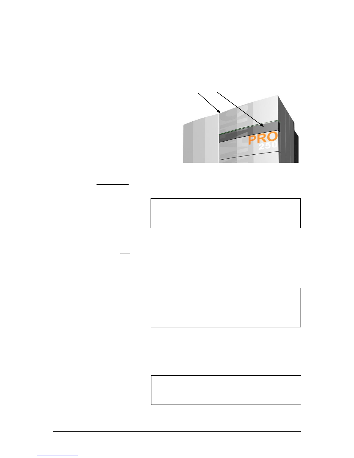
Power switch
Mains plug
Repair work
In an emergency: In the event of electric shock, disconnect
the power supply immediately.
Administer first aid. Call the duty doctor.
Fault rectification
Unauthorised modifications
Note: The power switch must remain switched on at
all times and may only be switched off when
the system is not in operation.
Danger: Risk of fatal injury from electric shock.
The mains power supply is brought to the
boiler via the plug marked Mains. That plug
and other components of the system remain
live even when the Power switch on the
control panel is switched off.
Danger: Repair work may only be carried out
by authorised technicians.
Touching live electrical components can
cause fatal injury.
Even when the Power switch is OFF some
components of the system are still live.
Therefore, when carrying out repair work it is
imperative that the power supply to the
heating system is completely disconnected by
means of the "mains plug" or a circuit
breaker.
Note: If faults occur, the causes must first be
eliminated on the basis of the information
message on the display (F0...) before
resuming operation by means of the Quit
button.
Note: Do not make any unplanned changes to the
settings or any modifications to the heating
system.
Loss of guarantee entitlement
Page 8
PRO Operating Instructions
8
Servicing work
Emptying ash
Boiler cleaning
Flue gas fan
Gaskets
In an emergency: Take the person affected into the
open air immediately. Call the duty doctor.
Air supply
Note: If there is more than one boiler in the same room, a
greater supply of fresh air must be provided.
Note: Service the boiler regularly or make use of
our Customer Service.
Danger: Glowing embers can cause fires.
The ash should only be removed from the
boiler or stored in non-combustible
containers.
Caution: Touching hot components can
cause skin burns.
The boiler must only be cleaned when it is
cold (flue gas temperature < 50°C)
Danger: Risk of injury from rotating parts.
The fan must only be removed when it is
disconnected from the power supply
(unplugged).
Danger: Risk of gas poisoning.
It is possible that flue gas could escape if
gaskets are damaged.
Have defective gaskets replaced by an
authorised technician.
Danger: Risk of suffocation
Inadequate air supply can be fatal.
Make sure there is an adequate supply of air.
Page 9
PRO Operating Instructions
9
Flue draught regulator
Safety clearances
Entering the fuel storeroom
Filling the storeroom
Danger: Risk of detonation.
A flue draught regulator with a pressure surge
compensator is an essential requirement.
Danger: Fire risk.
Do not store any flammable items in the close
vicinity of the boiler.
Follow the local regulations.
Danger: Risk of injury!
Only enter the store room when the
system is switched off. Always shut off
the power supply before entering.
Affix a sign to the storeroom door.
Keep the storeroom doors locked.
Danger: Combustible gases in storeroom!
When filling the fuel storeroom from a
tanker truck or using a pressure-filling
system, it is imperative that the boiler is
shut down.
If this rule is ignored, flammable and
poisonous gases can be drawn into the
storeroom.
Page 10
PRO Operating Instructions
10
Protection against freezing
Emergency fire extinguishing system
Fire extinguisher
Note: Anti-freeze function.
The system can only perform its freezing
prevention function if sufficient fuel is
available and there are no faults.
Note: Provide a fire extinguisher.
There must be a fire extinguisher placed
immediately outside the boiler room door.
Note: Contact our Customer Service.
If the emergency fire extinguishing system
has been triggered, it is always due to a fault
in the heating system.
Page 11
PRO Operating Instructions
11
3 System components PRO-03-00-00-00-01-BADE
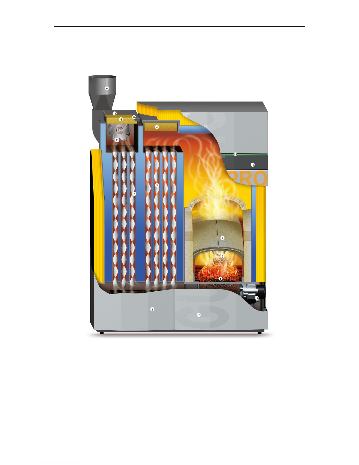
3.1 Cutaway diagram of PRO
1.) Stepped grate – primary air
2.) Domed swirl chamber
3.) Photosensor
4.) Inspection cover
5.) Helix baffles
6.) Heat exchanger
7.) Flue draught fan
8.) Automatic cleaning mechanism
9.) Flue pipe
10.) Oxygen sensor
11.) Flue gas sensor
12.) Grate motor
13.) Ash collecting device
14.) Menu-based touch-screen controller
15.) LED status indicator
Page 12

PRO Operating Instructions
12
4 Safety systems PRO-04-00-00-00-01-BADE
To prevent the boiler overheating, the controller reduces the
heat output in certain situations. If the boiler still threatens to
overheat, the controller responds according to a set of defined
safety levels.
Safety level 1 10°C above specified temperature
The drive motor stops the fuel feed system and the flue
draught fan shuts down.
Safety level 2 Boiler temperature over 95°C
All heating pumps and the cylinder charging pump are
switched on to carry heat away from the boiler.
Safety level 3 Boiler temperature over 100°C
The STL (safety temperature limiter) trips and switches all
boiler control functions off while the pumps continue to run.
The system remains switched off even if the boiler
temperature drops back below 90°C. The system must not be
started up again until any faults have been rectified and the
boiler has been checked.
Power failure The controller, the flue draught fan and all pumps switch off
due to lack of electricity if there is a power cut. The glowing
fuel bed on the grate continues burn with the natural draught
of the flue. As this operating mode is not ideal, a larger
amount of ash collects on the grate as well. As soon as the
electricity supply is restored, the controller takes control of the
heating system again.
Outer casing door open
The drive motors stop feeding the boiler with fuel
The flue draught fan switches to maximum extraction speed
If the outer casing door is closed again within 60 seconds,
combustion is continued
On the stoker duct The stoker duct and feeder box are designed to be completely
air-tight as far as the fire safety flap. That means that any
burn-back is extinguished by lack of air. The fire safety flap is
tested and approved as a burn-back prevention device. A
positioner motor opens and closes the flap. Fuel delivery does
not start until the flap is completely open. If the event of a fault
or a power failure, the flap closes automatically of its own
accord. When the boiler is in operation, the controller prevents
burn-back into the stoker auger by replenishing the fuel. In
addition, a sensor monitors the temperature in the vicinity of
the stoker auger. In that way, burning fuel is continually
pushed back out of the auger duct. This burn-back prevention
system always functions unless the electricity supply to the
boiler system is cut off.
Page 13
PRO Operating Instructions
13
On the fuel store outfeed unit Required in all countries
In addition, between the end of the fuel outfeed unit and the
burn-back prevention device there is a sprinkler unit that is
used instead of the temperature monitor with fuel stores with
a capacity not exceeding 50 m³ and is triggered at 55°C.
When the sprinkler is triggered, the sloping outfeed auger
enclosure – which also serves as a burn-back inhibiting device
– is completely flooded. The quantity of water required to do
so is at least 20 litres. If the temperature drops back below
55°C, the flooding is stopped.
Overfill prevention
The overfill prevention function is triggered by the fill level
sensor in the fuel chute or the contact switch on the overfill
prevention cover. If the fill level sensor trips, the auger A1
stops and the auger G1 continues running. If the sensor
remains on for longer than 10min, the overfill fault is
generated. If the overfill prevention cover switch trips, the
auger A1 is stopped after 3 seconds and the overfill fault
registered immediately.
Fuel stores > 50 m³ Requirement in Austria
A temperature monitor connected to a warning device must be
installed in the fuel storeroom at the point where the fuel
conveyor exits the fuel store and enters the boiler room. A
visual and audible warning device must be triggered when the
temperature exceeds 70°C.
Manually operated fire extinguishing facility
This fire extinguishing facility is for the purpose of combating a
fire seated in the fuel storeroom in the area of the outfeed unit
and is manually actuated. It consists of conduit piping with a
minimum size of DN 20 and is to be fitted in the fuel storeroom
immediately above the fuel conveyor close to its exit point
through the wall or ceiling and positioned so as to obtain the
maximum possible fire extinguishing effect. The conduit piping
is to be connected directly to a pressurised water supply and
provided with a stop tap located in the boiler room. That tap
must be identified by a sign carrying the inscription "Fuel
storeroom fire extinguisher". The design of the fire
extinguishing facility must be such that it cannot be damaged
by the delivery of fuel into the fuel store or by the fuel outfeed
equipment.
Note: The sprinkler system must be connected
on all systems regardless of local
regulations.
Page 14
PRO Operating Instructions
14
5 Description of control panel PRO-05-00-00-00-01-BADE
The appliance has a large touch-screen control panel with a
menu-based interface. All settings can be entered by pressing
the "buttons" on the touch screen. Information messages and
fault indications are displayed on the screen.
1-2 3
Power switch (1) Normally remains permanently switched on. The power switch
may only be switched off when the system is not in operation.
STL (2) The safety temperature limiter (STL) trips if the system
overheats → heating by the appliance is suspended.
If the STL has tripped, identify and eliminate the cause and
then press in the STL button as far as it will go using a
suitable object.
Touch-screen display (3) Pressing lightly with your fingertip on the relevant buttons on
the display opens the various programme levels and menus
where you can make changes to the settings.
Note: When carrying out repairs or servicing work,
the system must also be fully isolated from
the mains by unplugging the power lead.
Note: The system must not be started up again
until any faults have been rectified and the
boiler has been checked. If necessary, a
heating engineer must be called in.
Note: Never use sharp objects such as ball-point
pens or the like to operate the touch screen.
Page 15
PRO Operating Instructions
15
6 Overview of menu and levels PRO-06-00-00-00-01-BADE
Fault screen
Status info
Boiler info
MK Controller 0
info
MK Controller 1
info
MK Controller 2
info
Thermal store HP0
info
User Level
▲
Boiler enabling
Service level
Information level
Parameters menu
▼
Programme
▼
▼
User Level
Service level
CODE User menu
Programme level
Parameters menu
CODE Reset data
Heating circuit 0
▼
Boiler parameters
Fault list
Heating circuit 1
▲
Off
House level
Test program
Heating circuit 2
Normal Commissioning
Heating circuit 3
Hot water HC0 parameters
Heating circuit 4
Heating HC1 parameters
Heating circuit 5
Low HC2 parameters
Heating circuit 6
Low until HC3 parameters
Heating circuit 7
Recharge HW HC4 parameters
Heating circuit 8
Manual HC5 parameters
DHW 0
Grate cleaning HC6 parameters
DHW 1
HC7 parameters
DHW 2
Note:
Menus shown with a dashed border only appear if
activated on the Commissioning menu.
Changes to the settings on the Service and
Parameters levels may only be made with the
agreement of GUNTAMATIC.
HC8 parameters
Th/store pump HP0
DHW0 Parameters
Boiler cascade
DHW1 Parameters
User menu
DHW2 Parameters
Detail View
HP0 parameters
Date/Time
System settings
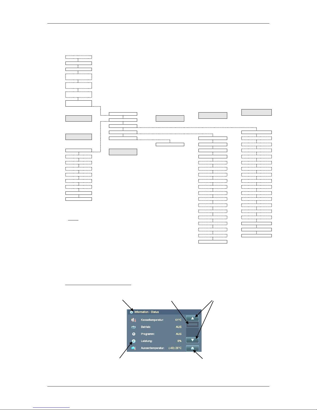
Layout of touch-screen display
Header Scroll bar Scroll buttons
Symbols Select button
Page 16
PRO Operating Instructions
16
6.0 Information level
The scroll buttons are used to navigate up or down through the menus.
Touching the House button on the display opens the House Level menu.
1) Note: Only shown if the function Network System Controller or Heating Circuit Controller has been activated.
Only one of the functions Network System Controller or Heating Circuit Controller can be programmed.
The two functions cannot be used simultaneously on the same boiler.
2) Only temperatures from the top and bottom thermal store sensors are shown on the Info Level.
(If 5-sensor thermal store management is activated, the temperatures from the thermal store middle sensors are shown in Detail View.)
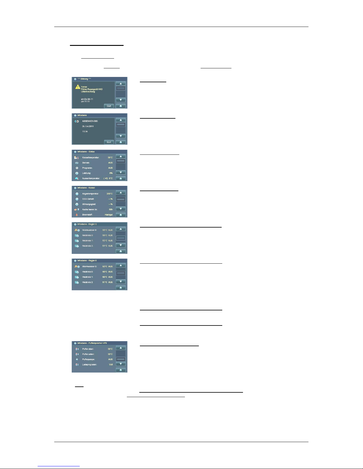
Fault screen → highest priority
Plain-English fault messages are displayed and saved
Fault is acknowledged by pressing Quit button
1)
Information level → Only shown if the programme "Low until" has been activated
Disappears after the set time has elapsed
Can be prematurely deactivated by pressing Quit button
Info Level – Status
Shows boiler temperature
Shows boiler operating mode
Shows selected programme
Shows boiler output
1)
Shows outside temperature → Figure in brackets = average temperature
Info Level – Boiler
Shows flue gas temperature
Shows CO2 level
Shows efficiency
Shows time in hours until ash warning is triggered
Shows fuel setting
1)
Info Level – Network system controller → (NSC)
Shows domestic hot water temperature and operating mode for cylinder 0
Shows operating mode for network system 0 → Pumped network system
Shows operating mode for network system 1 → Pumped or mixer-valve network system
Shows operating mode for network system 2 → Pumped or mixer-valve network system
1)
Info Level – Heating circuit controller 0 → (HCC 0)
Shows domestic hot water temperature and operating mode for cylinder 0
Shows operating mode for heating circuit 0 → Pumped heating circuit
Shows operating mode for heating circuit 1 → Pumped or mixer-valve heating circuit
Shows operating mode for heating circuit 2 → Pumped or mixer-valve heating circuit
1)
▼
Info Level – Heating circuit controller 1 → (HCC 1)
1)
▼
Info Level – Heating circuit controller 2 → (HCC 2)
2)
Information – Thermal store → (HP0)
Shows thermal store temperature at top
Shows thermal store temperature at bottom
Shows thermal store pump operating mode
Shows charging programme
Page 17

PRO Operating Instructions
17
6.1 House level
Pressing the buttons on the left-hand side opens the various menus.
Touching the Info button returns you to the Info Level menu.
6.1.1 Boiler enabling
Setting Boiler enabling to Off shuts down the boiler.
Network systems or Heating circuits continue to run.
3) Options → AUTO Boiler enabling dependent on enabling switch 22/23 on the boiler circuit board
(Enabling switch closed > Burner active on demand, heating circuit controller active)
(Enabling switch open > Burner off, heating circuit controller active)
→ OFF Boiler not enabled regardless of enabling switch 22/23 on the boiler circuit board
(Enabling switch closed > Burner off, heating circuit controller active)
(Enabling switch open > Burner off, heating circuit controller active)
6.1.2 Programme
Pressing the buttons on the left-hand side opens the programme.
4) The anti-freeze function is only active in OFF mode.
5) Other programme buttons are only visible if network system or heating circuit controller is activated.
Boiler enabling
See Section 6.1.1
Programme
See Section 6.1.2
User Level
See Section 6.1.3
Service level → CODE required
See Section 6.1.4
Parameters menu → CODE required
See Section 6.1.5
3)
Facility for setting boiler enabling
3)
4)
Heating and hot water switched off → Anti-freeze function active
Heating mode without network system or heating circuit controller activated
Manually switches on stepped grate for cleaning purposes
Other function buttons:
5)
→ NORMAL programme
Heating and hot water mode (DHW as per timer prog.)
5)
→ HOT WATER programme
Hot water on as per summer DHW timer programme
5)
→ HEATING programme
Heating mode day and night (DHW as per timer programme)
5)
→ LOW programme
Low-temperature mode day and night (DHW as per timer
programme)
5)
→ LOW UNTIL programme
Low-temp. mode until a specified time (DHW as per timer prog.)
5)
→ RECHARGE HOT WATER programme
Water heating outside programmed charging times (max. duration
90min)
Page 18

PRO Operating Instructions
18
6.1.3 User Level
The number of menus depends on the configuration.
6) Note: Only one of the functions Network System Controller or Heating Circuit Controller can be programmed.
The two functions cannot be used simultaneously on the same boiler.
7) Functions are only displayed if external heating circuit controller is activated.
6.1.3.1 User menu
The number of functions depends on the configuration.
8) After the ash container has been emptied (box or auto ash extraction system) it has to be confirmed on the Ash Emptied menu
by pressing the buttons YES and OK.
9) Options: Pellets 1 Quality ENplus A1 (standard quality)
Pellets 2 Quality ENplus A2
Woodchips 1 Soft wood (W > 25% - low quality)
Woodchips 2 Mixed soft and hard wood (W > 15-30% - standard quality)
Woodchips 3 Hard wood (W < 15% - high quality)
User menu → User settings
See Section 6.1.3.1
Thermal store pump HP0 menu
See Section 6.1.3.2
Detail View menu
Date/Time menu
Other function buttons:
6)
→ Network System 0-2 menu
See Section 6.1.3.3
6)
→ Network System 0-8 menu
See Section 6.1.3.4
→ DHW Cylinder 0-2 menus
See Section 6.1.3.5
7)
→ Supplementary DHW Cylinder 0-2 menu
See Section 6.1.3.5
7)
→ Feeder Pump 0-2 menu
See Section 6.1.3.6
7)
→ Charging Pump 0-2 menu
See Section 6.1.3.6
→ Boiler Cascade menu
See Section 6.1.3.7
Function buttons:
8)
→ Ash Emptied function
→ Ash Warning function → Time interval until ash warning appears (adjustable)
→ De-ashing function → For manually starting de-ashing
9)
→ Fuel parameters
→ Enable HCC 0 function → Only affects the district heating function
→ Enable HCC 1 function → Only affects the district heating function
→ Enable HCC 2 function → Only affects the district heating function
→ Fill Auger function → Sequence is not automatically switched off!
→ Flue Gas Testing function → Controller set to FGT Test/CO2 Test
→ Outfeed Auger function → For switching between A1a/b - Activated in System Settings
→ De-ashing Lockout function
→ Language function
Page 19

PRO Operating Instructions
19
6.1.3.2 Thermal store pump HP0 menu
10) Thermal store only charged during charging times enabled on menu
11) Linear boiler output reduction if the set medium output limit is exceeded
6.1.3.3 Network System menu
6.1.3.4 Heating Circuit menu
12) Options → Auto Network system/Heating circuit is switched ON/OFF according to demand and timer programme.
→ Off The network system/heating circuit is switched off.
→ Constant The network system/heating circuit pump runs continuously; with mixer-valve network systems/heating
circuits, the mixer valve is not operated
13) Modulation to daytime required temperature is only possible in conjunction with a room stat or room controller; raising or
lowering the required temperature shifts the heating curve up or down accordingly.
14) Modulation to night-time required temperature is only possible in conjunction with a room stat or room controller; in addition, the
outside temperature must be below that set in menu option Night OFF OT (hysteresis 2°C)
15) Options → 0% No room effect programmed
→ 25% Modulation of room temperature based 25% on room temperature and 75% on outside temperature.
→ 50% …
→ T 1°C If the required room temperature is exceeded by 1°C the heating circuit pump is switched off.
→ T 2°C …
16) A higher heating characteristic figure produces a higher required flow temperature at the same outside temperature
17) If the temperature drops below the set temperature during the low-temperature phase, the boiler heats to the required night-time
temperature.
18) The set outside temperature is exceeded during the heating phase, the heating circuit is switched off.
Function buttons:
→ Pump Mode function
10)
→ Thermal store timer programme parameters
→ Thermal store required temp. → effective for thermal store top sensor (T3)
→ Thermal store min temp. → effective for thermal store top sensor (T3)
→ Thermal store min charge
11)
→ Medium output limit parameters
Function buttons:
12)
→ Pump Mode function
→ Timer programme parameters Facility for setting heating and low-temperature times
→ Daytime base point parameters
→ Night-time base point parameters
16)
→ Heating curve parameters
17)
→ Night OFF OT function
18)
→ OT Off function
Function buttons:
12)
→ Pump Mode function
→ Timer programme parameters Facility for setting heating and low-temperature times
13)
→ Daytime required temp parameter
14)
→ Night-time required temp parameter
15)
→ Room effect parameter
16)
→ Heating curve parameters
17)
→ Night OFF OT function
18)
→ OT Off function
Page 20

PRO Operating Instructions
20
6.1.3.5 Hot Water menu
Supplementary Hot Water
19) Options → Auto The pump is switched ON/OFF according to demand and timer programme
→ Off The pump is switched off
→ Constant The pump runs continuously
20) All charging times programmed in the DHW timer programme are active when the programme is set to NORMAL.
21) All charging times programmed in the Summer DHW timer programme are active when the programme is set to HOT WATER.
22) Options → No During charging of DHW cylinder, network systems/heating circuits can be enabled.
→ Yes During charging of DHW cylinder, network systems/heating circuits cannot be enabled.
6.1.3.6 Feeder Pump menu
Charging pump
23) Options → Auto The pump is switched ON/OFF according to demand
→ Off The pump is switched off
→ Constant The pump runs continuously
24) Options → Full The thermal store is fully charged
Charging switches off when the required thermal store temperature at T3 is reached and also the
required thermal store temperature minus the parameter TSbtm-Boff (-10°C) is reached at T2
→ Part The thermal store is partially charged
Charging switches off when the required thermal store temperature is reached at T3 (= parameter
TS top-B Off)
25) Thermal store only charged during the charging times enabled
Function buttons:
19)
→ Pump Mode function
20)
→ DHW timer programme parameters
21)
→ Summer DHW timer programme parameters
→ DHW required temp parameter
22)
→ DHW priority parameter
→ Recharge DHW function → Maximum duration 90 minutes
Function buttons:
23)
→ Pump Mode function
24)
→ Charging programme parameters
25)
→ Timer programme parameters
→ Thermal store required temp. → effective for thermal store top sensor (T3)
→ Thermal store min temp. → effective for thermal store top sensor (T3)
Page 21

PRO Operating Instructions
21
6.1.3.7 Boiler Cascade menu
The Boiler Cascade menu is only visible on boiler A.
26) After the set time has elapsed, the boiler that has completed the fewest hours of duty in the cascade system is always started up
first.
27) Options → P ON When the boiler already started reaches the output set for P ON, the parameter Cut-in Time is
activated; if the boiler is still operating at the output set in the parameter P ON when the Cut-in
Time has elapsed, the next boiler is started up.
→ P OFF When the total output of the boilers running falls below the output set for P OFF, the last boiler
started is shut down again.
28) If the set outside temperature is exceeded, the boiler concerned is switched off.
29) As soon as the output of the boiler in operation falls below the level set in the parameter P OFF EXT Hyst, the boiler operated via
the EXTERNAL output (e.g. a peak load boiler) is switched off.
If multiple boilers are running, the total output of all boilers in operation applies.
6.1.4 Service Level (Expert)
The number of menus depends on the configuration.
Function buttons:
26)
→ Boiler Changeover function → 0h = No boiler changeover
→ Cut-in Time parameter
27)
→ Cut-in Output parameter
28)
→ Enable OT function → Function can only be used if an outside-temperature sensor is connected to boiler A.
→ EXTERNAL Mode function → An EXTERNAL boiler (e.g. peak load boiler) can be permanently switched off
29)
→ P OFF EXT Hyst parameters
Reset Data menu → Service parameters/software update ………
See Section 6.1.4.1
Fault List menu
Test Program menu
Commissioning menu
See Section 6.1.4.2
HP0 Parameters menu → Thermal store HP0 ........................
See Section 6.1.4.3
System Settings menu → Service parameters ……...........
See Section 6.1.4.4
Other function buttons:
→ Network System (NK) 0-2 ..................................................................................
See Section 6.1.4.5
→ Heating Circuit (HK) 0-8 Parameters …………………………..
See Section 6.1.4.6
→ DHW Cylinder 0-2 Parameters ........................................................................
See Section 6.1.4.7
→ Supplementary DHW Cylinder 0-2 Parameters
........................................................................
See Section 6.1.4.7
→ District Heating (FL) 0-2 Parameters
..................................................................................
See Section 6.1.4.8
→ Return Mixer Valve (RLM) Parameters
...........................................................................
See Section 6.1.4.9
Page 22

PRO Operating Instructions
22
6.1.4.1 Service menu Reset Data
6.1.4.2 Service menu Commissioning
Function buttons:
→ Load User Parameters function → For importing saved customer data if necessary
→ Save User Parameters function
→ Load Factory Parameters function → Imports only the modified or new parameters of a new software version
→ Reset Duty Hours function → Resets the duty hours counter to 0
→ Reset Servicing Time function → Resets the servicing timer to 0
→ Controller Reset function → Caution: Loads factory settings
→ Oxygen Sensor Calibration Reset function → Should always be carried out whenever oxygen sensor is replaced
Function buttons:
→ System:
Options:
PRO
→ Type:
Options:
175kW/250kW
→ Fuel outfeed
Options:
FLEX/AGIT
→ Feeder auger
Options:
No/Yes
→ Ash removal
Options:
◄◄◄◄/VAC/BOX
→ Fuel
Options:
Pellets 1/Pellets 2/Woodchips 1/Woodchips 2/Woodchips 3
30)
→ NSC present → Network system
controller
Options:
No/Yes
→ DHW 0 present
Options:
No/Yes
→ NS 0 mode
Options:
None/Pump
→ NS 1 mode
Options:
None/Pump/Mixer
→ NS 2 mode
Options:
None/Pump/Mixer
30)
→ HCC 0 present → Heating circuit controller
Options:
No/Yes
→ DHW 0 present
Options:
No/Yes
31)
→ HC 0 mode
Options:
None/Pump/Mixer
→ HC 1 mode
Options:
None/Pump/Mixer
→ HC 2 mode
Options:
None/Pump/Mixer
→ Source → Only with CP
Options:
Thermal store HP0
32)
→ District heating 0 mode
Options:
None/FP/◄◄◄/CP
33)
→ Supplementary 0
Options:
None/HWP/External
→ HCC 1 present → Heating circuit controller
Options:
No/Yes
→ DHW 1 present
Options:
No/Yes
31)
→ HC 3 mode
Options:
None/Pump/Mixer
→ HC 4 mode
Options:
None/Pump/Mixer
→ HC 5 mode
Options:
None/Pump/Mixer
→ Source → Only with CP
Options:
Thermal store HP0
32)
→ District heating 1 mode
Options:
None/FP/◄◄◄/CP/EXT
33)
→ Supplementary 1
Options:
None/HWP/External
→ HCC 2 present → Heating circuit controller
Options:
No/Yes
→ DHW 2 present
Options:
No/Yes
31)
→ HC 6 mode
Options:
None/Pump/Mixer
→ HC 7 mode
Options:
None/Pump/Mixer
→ HC 8 mode
Options:
None/Pump/Mixer
→ Source → Only with CP
Options:
Thermal store HP0
32)
→ District heating 2 mode
Options:
None/FP/◄◄◄/CP/EXT
33)
→ Supplementary 2
Options:
None/HWP/External
→ HP0 mode
Options:
◄◄◄◄◄/Th store pump
→ Return mixer valve
Options:
No/Yes
→ Fill Auger
Options:
OFF/ON
→ Save User Parameters
Options:
No/Yes
Page 23

PRO Operating Instructions
23
30) Note: Only one of the functions Network System Controller or Heating Circuit Controller can be programmed on the boiler.
Network system mode or heating circuit mode
→ None Network system/heating circuit is deactivated
→ Pump Operation of the pumped circuit is controlled by the timer programme
→ Mixer Operation of the pump and the mixer valve is controlled by the timer programme
Room stat options (only possible with heating circuits)
→ None No room stat connected
→ RFF Analogue room stat is connected
→ RS Full Digital room controller is connected (facility for setting all heating circuits)
→ RS HC Digital room controller is connected (facility for setting assigned heating circuit only)
→ RS HCC Digital room controller is connected (facility for setting one heating circuit controller)
31) The heating circuit can only be set as a mixer-valve heating circuit if the Supplementary and District Heating functions are not activated.
32) The District Heating Mode function can only be activated if heating circuit 0 is not programmed as a mixer-valve heating circuit.
→ FP The district heating pump is controlled as a feeder pump (for setting see plumbing diagram)
→ TSP The district heating pump is controlled as a thermal store pump (for setting see plumbing
diagram)
→ CP The district heating pump is controlled as a charging pump (for setting see plumbing diagram)
33) The function Supplementary 0 can only be activated if heating circuit 0 is not programmed as a mixer-valve heating circuit.
→ None Function is deactivated
→ HWP An additional DHW cylinder can be activated
→ External Heat from an external boiler (e.g. oil boiler) can be requested using the Cascade function
6.1.4.3 Service menu HP0 Parameters
34) The boiler is started up when the thermal store temperature falls below the maximum temperature required by the heating circuit
controller minus the temperature set in the parameter TS top charge ON.
Example: Maximum temperature required by heating circuit controller = 55 °C
Setting for TS top charge ON = 6°C
The boiler starts up when the temperature at the thermal store top sensor (T3) is 49°C
35) With the partial charging programme the boiler is shut off when the temperature at the thermal store top sensor (T3) reaches
the thermal store required temperature plus the temperature set for the parameter TS top charge OFF.
Example: Required thermal store temperature = 70°C
Setting for TS top charge OFF = 5°C
The boiler is shut off when the temperature at the thermal store top sensor (T3) is 75°C
36) With full charging programme, the boiler is shut off as soon as the temperature at the bottom of the thermal store (T2) only
differs from the temperature at the top of the thermal store (T3) by the amount set for the parameter TS btm charge OFF
Example: Temperature at top of thermal store (T3) = 70 °C
Setting for parameter TS btm-B off = -10 °C
The boiler is shut off when the temperature at the thermal store bottom sensor (T2) is 60°C
37) This parameter specifies which controller the sensors of thermal store HP0 are connected to. If the thermal store sensors are
assigned to a heating circuit controller, no analogue room stats can then be used on that controller.
38) This function can be used to activate 5-sensor thermal store management (No = 2-sensor thermal store management).
Function buttons:
→ HP0 Mode function
Options:
Th/store pump
→ Enable HP0 parameter → Enabling temperature for output HP0
34)
→ Parameter TS top charge ON → Boiler demand via sensor T3
35)
→ Parameter TS top charge OFF → Boiler switched off via sensor T3 with charging programme PART
36)
→ Parameter TS btm charge OFF → Boiler switched off via sensor T2 with charging programme FULL
→ Parameter Delta-T Dist/h → District heating pipe heat loss
→ Parameter B-TS btm Diff. → Temperature difference between boiler and bottom of thermal store
37)
→ Parameter Sensor HP0
Options:
Boiler/HCC 0/HCC 1/HCC 2
38)
→ Supplementary Sensor function
Options:
No/Yes
Page 24

PRO Operating Instructions
24
6.1.4.4 Service menu System Settings
The number of parameters depends on the configuration.
39) Options → Terminal Data querying via Windows hyper terminal/display
→ DAQ Data querying via online recorder (only usable at factory)
→ GSM module Data querying, information messages and boiler control via GSM module
Function buttons:
→ System:
Options:
PRO
→ Type:
Options:
175kW/250kW
→ Fuel outfeed
Options:
FLEX/AGIT
→ A1/G1 Pellets 1, Pellets 2, …
Options:
Ratio of auger A1 to G1
→ Feeder auger
Options:
No/Yes
→ A2/A1 Pellets 1, Pellets 2, …
Options:
Ratio of auger A1 to G1 (if feeder auger activated)
→ A1a/b changeover
Options:
No/Yes
→ Ash removal
Options:
VAC; BOX
→ Fill level A1
Options:
No/Yes
→ Fill level A2
Options:
No/Yes
→ PS present
Options:
No/Yes
→ Calibrate PS
Options:
OFF/ON
→ PS compensation
Options:
Photosensor compensation setting
→ Air flap
Options:
No/Yes
→ Boiler cascade
Options:
No/A/B/C/D
→ Grate motor
Options:
Benzler/ABM
→ Flue draught
Options:
Cyclic
→ NSC present
Options:
No/Yes
→ HCC 0/1/2 present
Options:
No/Yes
→ Outside temp sensor
Options:
No/Yes
→ Oxygen sensor
Options:
No/NGK/Bosch
→ Oxygen sensor heating
Options:
AUTO/Constant
→ Calibrate oxygen sensor
Options:
OFF/ON
→ Oxygen sensor compensation
Options:
Oxygen sensor compensation setting
→ Oxygen sensor characteristic
Options:
0.0%/0.5%/-3.0%
→ BT comp 80°C
Options:
Boiler temp compensation setting
39)
→ PC monitoring
Options:
Terminal/DAQ/GSM module
→ GSM subscriber number 1
Options:
Subscriber number entry
→ GSM subscriber number 2
Options:
Subscriber number entry
→ SD logging
Options:
OFF/ON – Save setting
→ SD data
Options:
Summary
→ CID data
Options:
Manufacturer code
→ Network
Options:
No/Yes
→ DHCP
Options:
Manual/Via DHCP (if network activated)
→ IP address
Options:
10.0.0.25 (if DHCP set to Manual)
→ Subnet mask
Options:
255.255.255.0 (if DHCP set to Manual)
→ Gateway
Options:
10.0.0.1 (if DHCP set to Manual)
→ Pri DNS server
Options:
10.0.0.1 (if DHCP set to Manual)
→ Sec DNS svr
Options:
(if DHCP set to Manual)
→ NetBIOS
Options:
Kessel0001 (if DHCP set to Manual)
→ ABS pump time
Options:
Activates all pumps once a week for the set amount of time
→ HCP forced op
Options:
If boiler or thermal store overheats all heating circuit pumps switch on
→ Residual heat utilisation
Options:
Pump HP0 runs until temperature at boiler is below this figure
→ HCP A/F outside only with outside-temp
based controller
Options:
Only in OFF mode – All heating circuit pumps switch on if outside
temperature is below setting
→ HCP A/F Flow only with outside-temp
based controller
Options:
Required flow temperature if HCP A/F Outside is active
→ TÜV function
Options:
Raises boiler temperature until STL trips
→ ▼▼ Fault messages ▼▼
Page 25

PRO Operating Instructions
25
6.1.4.5 Service menu Network System Parameters
The number of parameters depends on the configuration.
40) Options → Pump Setting for network systems without mixer-valve control (Diagram PRO-01-02-01)
→ Mixer Setting for network systems with mixer-valve control (Diagram PRO-01-02-02)
41) If the twin pump function is activated, a return temperature sensor must be used for control purposes.
42) Each network system can be called for/switched off by an external controller using a 0-10V signal.
6.1.4.6 Service menu Heating Circuit Parameters
The number of parameters depends on the configuration.
CAUTION: The screed drying parameters must be set in consultation with the floor
layer.
Maintaining the specified temperatures is not possible in modulating control
mode but only when using automatic mixer valves. Maintenance of the
specified temperatures cannot be 100% guaranteed – due to various safety
circuits and special boiler functions, in exceptional cases the temperatures
can be significantly exceeded. If that is a problem in terms of damage to
building work, the screed drying function should be operated manually.
Function buttons:
40)
→ NK0-2 Mode function
Options:
None/Pump/Mixer
→ Mixer Valve Runtime function
→ Min Flow Temperature function → Only with mixer-valve circuits
→ Max Flow Temperature 1-2 function → Only with mixer-valve circuits
→ Boiler Overcompensation parameter
→ Enable NSP 0-2 parameter
→ Parallel Shift parameter
41)
→ Twin Pump function
Options:
No/Yes
→ Twin Pump Off Differential parameter
→ Twin Pump On Differential parameter
42)
→ Enable Ext. NS function
Options:
No/Yes
Function buttons:
→ HC 0-8 Mode function
Options:
None/Pump/Mixer
→ Room Stat 0-8 function
Options:
None/RFF/RS Full/RS HC/RS HCC
→ Mixer Valve Runtime function
→ Min Flow Temperature function → Only with mixer-valve circuits
→ Max Flow Temperature function → Only with mixer-valve circuits
→ Boiler Overcompensation parameter
→ Enable HCP 0-8 parameter
→ Parallel Shift parameter
→ Floor Screed Heating function
Options:
No/Yes
→ Flow Temp Increase parameter
→ Increase After parameter
→ Screed Heat Min Flow Temp parameter
→ Screed Heat Max Flow Temp parameter
→ Screed Heat Holding Time parameter → Number of days for which max flow temperature to be maintained
→ Start Screed Heating function
Options:
No/Yes
Page 26

PRO Operating Instructions
26
6.1.4.7 Service menu Hot Water Parameters
Supplementary Hot Water parameters
The number of parameters depends on the configuration.
43) If the temperature in the hot water cylinder falls below the required temperature by the hysteresis setting, the hot water cylinder is
heated up again.
6.1.4.8 Service menu Feeder Pump Parameters
Charging Pump parameters
The number of parameters depends on the configuration.
6.1.4.9 Service menu Return Mixer Valve Parameters
The number of parameters depends on the configuration.
44) Options → FIXED Return temperature is modulated to the specified temperature
→ Mixer Return temperature is modulated to the specified temperature depending on thermal store charge
45) Setting for temperature difference between boiler temperature and return temperature
46) Setting for minimum temperature difference between boiler temperature and return temperature at 100% thermal store charge
Function buttons:
→ DHW Present function
Options:
No/Yes/External
43)
→ DHW Hysteresis parameter
→ Enable DHW Pump parameter
→ Boiler Overcompensation parameter
Function buttons:
→ District Heating Mode function
Options:
None/FP/CP
→ Enable District Heating parameter → Enabling temperature for district heating pump
→ Parameter TS top charge ON → District heating pump demand via sensor T3
→ Parameter TS top charge OFF → District heating pump switched off via sensor T3 with charging programme PART
→ Parameter TS btm charge OFF → District heating pump switched off via sensor T2 with charging programme PART
→ Source parameter
Options:
ThStore 0/ThStore 1/ThStore 2/ThStore HP0
→ Parameter Delta-T Dist/h → District heating pipe heat loss
→ Parameter B-TS btm Diff. → Temperature difference between boiler and bottom of thermal store
Function buttons:
44)
→ Return Mixer Mode function
Options:
FIXED/AUTO/OPEN/CLOSED/OFF
→ Return Mixer Valve Runtime parameter
→ Required Return Temperature parameter
45)
→ Return Mixer Valve Delta T parameter
46)
→ Return Mixer Valve Delta T Min parameter
→ Startup Relief parameter
Options:
No/Yes
Page 27

PRO Operating Instructions
27
7 User settings PRO-07-00-00-00-01-BADE
7.1 Activating a heating programme
To activate the programme NORMAL, for instance, you proceed as
follows:
1) → Press the House level button
2) → Press the Programme button
3) → Press the NORMAL programme button
4) → Press the Back button
5) → Press the Info button
6) → The Info Level now shows the programme NORMAL
Page 28

PRO Operating Instructions
28
7.2 Deactivating a heating programme
To deactivate the programme NORMAL, for instance, you proceed as
follows:
1) → Press the House level button
2) → Press the Programme button
3) → Press the Programme Off button
4) → Press the Back button
5) → Press the Info button
6) → The Info Level now shows the programme OFF
Page 29

PRO Operating Instructions
29
7.3 Programming heating times
To program the timer programme for heating circuit 1, for instance, you proceed as
follows:
7.3.1 Programming en bloc
The same on and off times can be programmed for every day of the week.
1) → Press the House level button
2) → Press the User level button
3) → Press the Heating circuit 1 button
4) → Press the Timer programme 1 button
5) → Press the button for the day of the week to be set
6) → Press the ON or OFF time to be altered
7) → Use the and buttons to set the time
8) → To save the setting, press the button
To activate programming en bloc, press the same weekday button twice in
succession; all days are then highlighted and can be programmed
collectively to the same times
Page 30

PRO Operating Instructions
30
7.4 Changing the heating characteristic
To change the heating curve for heating circuit 1, for instance, you
proceed as follows:
Heating characteristic graph
1) → Press the House level button
2) → Press the User level button
3) → Press the Heating circuit 1 button
4) → Press the Heating characteristic 1 button
5) → Use the and buttons to set the heating characteristic
6) → To save the setting, press the button
20
30
40
50
60
70
80
-20-15-10-505101520
3,5
2,5
3,0
2,0
1,5
1,0
0,5
Outside temperature [°C]
Flow temperature [°C]
Page 31

PRO Operating Instructions
31
7.5 Changing the hot water temperature setting
To change the required temperature for cylinder 0, for instance, you proceed as
follows:
1) → Press the House level button
2) → Press the User level button
3) → Press the DHW cylinder 0 button
4) → Press the DHW required temp 0 button
5) → Use the and buttons to set the required temperature
6) → To save the setting, press the button
Page 32

PRO Operating Instructions
32
7.6 Analogue room stat
Installation site Fix the room stat on an internal wall at a height of approx.
1.5m. The most effective room is the one that is most
frequently occupied. In that room, the radiators must not be
fitted with thermostatic radiator valves (valves must be fully
turned on).
Note: The room stat should not be fitted in a position
where it will be exposed to warm sunshine or the
heat from a stove.
Changing room temperature The control knob on the room stat allows you to adjust the
required room temperature. Setting the control to a position in
the positive range (+) raises the required room temperature by
up to 3°C. Setting it to a position in the negative range (–)
lowers it by up to 3°C.
Note: Turning the control into the positive (+) or
negative (–) range means that the room
temperature shown in the Detail View will be
inaccurate. The room temperature shown will
only match the actual temperature when the
control knob is in the centre position.
Low: Heating mode OFF
(If the outside temperature is higher than the parameter Night Off OT)
Heating Mode ON → To Night-time Required Temperature
(If the outside temperature is lower than the parameter Night Off OT)
Normal: Heating and Low-temperature modes
(According to the times set in the timer programme)
Heating: Constant Heating mode → To Daytime Required Temperature
(Continuous heating day and night without low-temperature mode)
7.7 Digital room controller
The digital room controller offers various possible applications
which are defined during commissioning.
If the room controller is used to control room temperature, it
offers the same functions as the analogue room stat.
In addition, system data such as boiler operating mode, thermal
store temperatures, etc. can be retrieved.
Operating instructions The room controller is supplied with its own instruction manual.
Page 33

PRO Operating Instructions
33
8 Operating the heating system PRO-08-00-00-00-01-BADE
8.1 Starting up/Shutting down the system
Initial commissioning Initial commissioning and basic adjustment of the system may
only be carried out by GUNTAMATIC engineers or authorised
GUNTAMATIC agents.
Restarting Before starting up the system again in the autumn/winter,
carry out the annual check of the control and safety systems
to ensure they are safe and functional. We recommend that
you take out a maintenance contract so that the system
operates safely and economically.
Day-to-day operation Clean the heating system precisely according to the
instructions in the section Cleaning/Care. The amount of
cleaning work required is heavily dependent on the quality of
the fuel used and lower-quality fuels may necessitate more
cleaning work.
Shutting down the system The system only needs to be shut down at the end of the
heating season, if faults occur or in order to refill the fuel store.
To do so, set the system to the programme "OFF" and allow it
to cool down for approx. 120 minutes. The system can then be
shut down.
If the system is not used for extended periods (summer) also
isolate it from the power supply by disconnecting the mains
plug in order to prevent unnecessary lightning damage.
8.2 Heating system checks
Checking system pressure The operating pressure is normally between 1 bar and 2.5 bar.
If the system pressure is too low, malfunctions may result – if
necessary top up the water in the heating system.
Note Completely draining and refilling the system or
topping up a system filled with anti-freeze or treated
water must only be carried out by a heating
engineer.
Topping up the heating system water
The heating system water must be cold when topping up
→ make sure the heating system water temperature is
below 40°C.
Add water slowly until the required system pressure is
indicated on the system pressure gauge.
Bleed the heating system.
Check the system pressure again and add more water if
necessary.
Temperature-relief valve Firmly press in the red knob on the relief valve: → cools the
boiler using water from the domestic water system if the boiler
overheats; → in the event of malfunctions or leaks, call in your
heating engineer.
Page 34

PRO Operating Instructions
34
Sprinkler system Firmly press in the red knob on the sprinkler: → extinguishes
burn-back in the outfeed unit; → in the event of malfunctions
or leaks, call in your heating engineer.
Manual fire extinguisher (MFE) Check water supply/tank; → used to extinguish a fire in the
outfeed unit
Pressure-relief valve Turn the red knob on the safety set; → check for leaks and
correct operation; → in the event of malfunctions or leaks, call
in your heating engineer.
Expansion vessel If there are large pressure fluctuations between when the
heating system is hot and cold, check the charge pressure in
the expansion vessel; → in the event of malfunctions or leaks,
call in your heating engineer.
Boiler room ventilation Check that the air supply vents/ducts are clear.
8.3 Fuel quality
To ensure trouble-free heating with the boiler, the fuel must be
of the right quality.
Your GUNTAMATIC heating system is designed for burning
G30/G50 woodchips with a maximum moisture content of 35%
(W35), and pellets. However, it does not make sense to burn
fuels with a significant moisture content as a considerable
proportion of the energy has to be used to evaporate the
water in the fuel. The amount of ash produced in practical
terms essentially depends on how clean the fuel is. With
woodchips, the fine ash component increases with higher
proportions of rotting wood, needles, etc.
Note: Dust emission from the flue is related to the
quality of the fuel.
Dry fuels enable substantially greater levels of
efficiency.
Page 35

PRO Operating Instructions
35
8.4 Fuels
8.4.1 Woodchips
Woodchips are made from woodland management waste or
trees and should have a maximum water content of 35% so
that they are suitable for storage. After felling, chipping wood
should be left to season for at least one summer in an airy and
sunny location.
Ideal water content of woodchips = < 20%
Make sure that the average woodchip size of G30/G50
woodchips is not exceeded as otherwise the auger conveyors
may jam or be noisy in operation. Long, thick shavings can
cause problems with the fuel outfeed system.
Average length of G30 woodchips = 30mm
Average length of G50 woodchips = 50mm
Only burn G50 woodchips if they are of the best quality.
Energy density/volume
1 cu m bulk volume
Spruce
750 kWh
1 cu m bulk volume
Pine
880 kWh
1 cu m bulk volume
Larch
960 kWh
1 cu m bulk volume
Oak
1050 kWh
1 cu m bulk volume
Beech
1050 kWh
Quality classes
Water
content
Equivalence
W20 air dried
< 20%
120%
W30 suitable for storage
>20% <30%
110%
W35 restricted suitability for
storage
>30% <35%
100%
W40 damp (not suitable for storage)
>35% <40%
85%
W50 freshly harvested (not suitable
for storage)
>40% <50%
65%
Properties
Calorific value
3.3 – 4.0 kWh/kg
Bulk weight
180 kg – 270 kg/cu m bulk volume
Primary energy factor
fP = 0.2
G30 woodchips to ÖNORM M7133
Coarse component →
maximum 20%
(of the total quantity)
Cross-sectional area max. 3cm²
Max. length 8.5cm
Main component → 60 to
100%
Nominal length 30mm
Cross-section betw. 2.8 and 16mm
Fine component →
maximum 20%
(of which max. 4% ultra-fine)
Cross-section less than 1mm
G50 woodchips to ÖNORM M7133
Coarse component →
maximum 20%
(of the total quantity)
Cross-sectional area max. 5cm²
Max. length 12cm
Main component → 60 to
100%
Nominal length 50mm
Cross-section betw. 5.6 and 31.5mm
Fine component →
maximum 20%
(of which max. 4% ultra-fine)
Cross-section less than 1mm
Page 36

PRO Operating Instructions
36
8.4.2 Pellets
There are a number of points to observe when ordering wood
pellets in order to ensure that they are of perfect quality.
Reliable and trouble-free operation of the boiler and the
conveying systems can only be guaranteed with high-quality
pellets. Therefore we strongly advise that only quality-assured
products are used that are guaranteed as such by the
manufacturer.
Important quality criteria
Lowest possible dust content
Surface should be shiny and very hard
No additives or binding agents
The ideal length is 20 mm
The price should always be a secondary consideration after
the quality criteria. If the required quality criteria are not met,
problems with combustion and/or conveying, increased wear
and pellet consumption can result. Therefore, you should not
accept quality standards that do not meet the above
requirements.
Properties
Calorific value
4.9 kWh/kg
Bulk weight
>650 kg/m³
Pellet size (length)
5 - 30 mm
Pellet diameter
5 - 6 mm
Water content
8 – 10 %
Ash content
< 0.5%
Quality assurance for pellets Europe ENplus A1/A2
Austria: ÖNORM M 7135
Germany: DIN 51731
Switzerland: SN 166000
Note: Dust emission from the boiler flue is heavily
dependent on the dust content of the fuel.
Page 37

PRO Operating Instructions
37
8.5 Filling/Refilling the fuel store
Initial filling When first filling the storeroom and every time it is refilled after
being completely emptied, do not immediately fill the store
completely.
Filling Fill the storeroom with fuel to a depth of 50cm, spreading it
evenly over the agitator and agitator arms. Then select the
function Fill Auger from the User menu and run the agitator
briefly so that the agitator arms can retract under the agitator
cover plate. The fuel storeroom can then be filled up to the
maximum permissible bulk storage height.
Refilling Before filling, and especially before refilling, the condition of
the storeroom/remaining fuel should be examined. Residual
fuel should be completely used up and/or dust removed so
that old fuel and dust does not accumulate over a period of
years. Broken pieces of wall or plaster and foreign objects of
any kind (pieces of wood, stone, metal, etc.) can cause faults
and/or damage throughout the system.
Maximum bulk storage height
Woodchips
max. 5.0 m bulk storage height
Pellets
max. 2.5 m bulk storage height
Caution: The heating system must be set to Off mode
at least 1 hour before the fuel store is filled.
On no account must the fuel store be filled
while the heating system is in operation!
Note: Failure to observe the above limit can result in
damage to the agitator and the fuel outfeed
unit.
Caution: Risk of injury from rotating parts.
Only enter the store room when the system is
switched off. Always shut off the power supply
before entering.
Page 38

PRO Operating Instructions
38
8.6 Combustion air supply
On PRO heating systems, no adjustments should be made to
the combustion air supply. The diagrams below are intended
only to illustrate the positions of the components.
Primary air
The primary air supply (A) is preset on the front of the boiler
and must not be altered.
Secondary air
The secondary air supply is electronically controlled by a
servo motor (B) on the rear of the boiler.
Page 39

PRO Operating Instructions
39
8.7 Emptying the ash
On a 250kW heating system operated at maximum output for
approx. 10 hours a day, the ash box on the rear of the boiler
requires emptying at intervals that can vary from every few
days to as much as 8 weeks, depending on the fuel quality.
The emptying interval is substantially shorter with low-quality
fuels such as those with a high bark content, for instance.
When burning pellets, the emptying interval can be as long as
100 days.
Procedure On the Boiler Enabling menu set Boiler Enabling to OFF and
wait until the mode indication changes to OFF mode. Unfasten
the ash box and pull it out of the ash duct to the rear. You can
then wheel the ash box easily to the emptying point by pulling
up the handlebar and fitting the cover. The display shows the
information message "Ash box open".
After emptying the ash box, replace it on the ash duct and
fasten it in place. The information message "Ash box open"
disappears.
Please pay particular attention to ensuring that it is properly
sealed.
On the Boiler Enabling menu reset Boiler Enabling to AUTO.
Resetting the ash warning Every time the ash box is emptied, you must reset the ash
warning on the User menu. To do so, select the option Ash
emptied, change the setting to YES and press the OK button
to confirm.
The time until the ash warning is issued can be adjusted by
selecting Ash Warning on the User menu.
Danger: Glowing embers can cause fires.
The ash should only be removed from the
boiler or stored in non-combustible
containers.
Page 40

PRO Operating Instructions
40
9 Cleaning/Care PRO-09-00-00-00-01-BADE
Cleaning The sophisticated cleaning system on a GUNTAMATIC
heating system means that regular cleaning work is
substantially reduced. All that is required is regular emptying
of the ash.
The flue must be regularly swept. At the same time, the flue
connecting pipe should be cleared of ash.
Depending on how dirty the boiler becomes (which is
determined by the quality of the fuel burned), interim cleaning
may be required, for which the precise procedure is described
on the following pages.
If the heating system is subject to heavy use, complete
cleaning may be required twice a year but should be carried
out at least once a year following the complete cleaning
procedure, which is also described on the pages that follow.
Care If the casing panels or the controls become dirty, they are best
cleaned with a soft, damp cloth. Use only gentle, solvent-free
cleaners to dampen the cloth. On no account should solvents
such as alcohol, white spirit or thinners be used as they will
attack the surface of the boiler.
Note:
For safety reasons you must only carry out
servicing and cleaning when the heating
system is switched off and disconnected from
the mains, and has cooled down.
Servicing work inside the fuel storeroom must
only be carried out under the supervision of a
second person, who must be outside the
storeroom.
There is a risk that accumulation of
carbon monoxide in the fuel storeroom
could endanger your life.
In particular, you should follow the safety
instructions in Section 2.
Page 41

PRO Operating Instructions
41
9.1 Cleaning the fuel store
The fuel outfeed auger and the fuel store must be completely
emptied (ideally vacuumed out) at least once every 3 years so
as to prevent problems with the outfeed system due to dust
accumulation.
9.2 Interim cleaning
Interim cleaning must be carried out at intervals of between 2
weeks and 3 months depending on the load on the heating
system and the quality of the fuel burned, and involves the
following steps:
1. On the Boiler Enabling menu, set the system to OFF and
allow it to cool down for at least 1 hour.
2. Before starting intermediate cleaning, start the function
De-ashing on the User menu and wait until the system
automatically completes the sequence.
3. Undo the 4 screws on the combustion chamber door and
open it.
4. Clean the ash off the stepped grate (A) and clean out the
grate slots with a screwdriver, for example.
5. Clean the deposits off the sides of the combustion
chamber (B) using the tools supplied.
6. Remove the combustion chamber firebrick cover (C).
7. Vacuum clean both sets of dome bricks (D), top and
bottom.
8. Refit the combustion chamber firebrick cover (C).
9. Close the combustion chamber door and secure with the
securing screws.
10. On the Boiler Enabling menu set Boiler Enabling to
AUTO.
Caution: Risk of injury from moving parts.
Do not carry out any other cleaning or
maintenance operations while the De-ashing
function is active.
Page 42

PRO Operating Instructions
42
9.3 Complete cleaning
Depending on how heavily the system is used, complete
cleaning may be required twice a year but should be carried
out at least once a year.
Carry out steps 1-9 precisely as described in the section
Interim cleaning. In addition, complete cleaning also requires
the operations listed below.
1. Isolate the system from the mains power supply.
2. Open the inspection cover (B) of the ash extraction
system.
3. Roughly clean the inside and remove any foreign objects
such as stones, etc.
4. Also check the ash flaps (C) of the transverse augers for
foreign objects and free movement.
5. Open the two inspection covers (D) on the top of the
boiler and vacuum out the flue gas headers – also
vacuum out the flue connecting pipe as far as flue draught
fan.
6. Open the inspection cover (E) on the rear of the boiler and
check the inside for coarse particles.
7. Remove the photosensor from its holder and clean with a
soft cloth – also check the opening into the combustion
chamber and clean it if necessary.
8. Finally close all inspection covers again, taking care to
secure and seal them properly.
9. Unscrew the oxygen sensor (G), clean it with a soft brush
and screw it back in tightly.
10. Open the inspection cover on the outfeed unit and remove
the dust in the area indicated (H).
11. On the Boiler Enabling menu set Boiler Enabling to
AUTO.
9.4 Cleaning at the end of the heating season
If the system is unused for an extended period in the summer
months, complete cleaning must be carried out.
Afterwards, all metallic components of the firebox, heat
exchanger and flue gas box must be sprayed with an oilbased corrosion-proofing spray.
Caution: Risk of injury from moving parts.
Fully isolate the system from the mains power
supply. Only then should you carry out any
cleaning work on the heating system.
Page 43

PRO Operating Instructions
43
10 Rectifying faults PRO-10-00-00-00-01-BADE
Fault
Cause/Function
Remedy
Control panel cannot be
switched on
Power supply disconnected
Fuse blown
Check master switch, mains plug
and/or power supply lead between
circuit boards
Check fuse in supply lead and on the
control panel circuit board
Smoke escaping into boiler
room
Inspection covers on boiler leaking
Flue pipe leaking
Flue draught regulator unfavourably
positioned
Flue not clear
Flue not providing any draught
Eliminate leaks
Eliminate leaks
Consult flue installer
Check flue
Check flue
Heat output too low
Boiler very dirty
Heating system inadequately balanced
Flue draught in chimney flue too low
Carry out complete cleaning
Balance heating system and pumps
Increase flue draught in chimney flue
Detonation
Detonation is only possible if the firebox
is overfilled.
Carry out complete cleaning
or consult engineer if necessary
Difficult to limit output
Flue draught is too great
Large fluctuation in heat draw
Re-adjust flue draught regulator
Stagger heating system component
demand over time
Overheating
Fault code F04
STL tripped
The amount of heat produced cannot be
dissipated – it may be that a pump has
failed or is not running.
The cause of the boiler overheating
must be identified.
Consult engineer if necessary.
Check the fuses on the boiler
Drive motor too noisy
Noise transmission
If necessary, place the adjustable
feet of the boiler on rubber pads
Fan too noisy
Fan is dirty
Fan or blades loose
Noise created by bends or rigid pipe
junctions with chimney flue
Fan bearing defective
Clean fan
Eliminate cause
Fit insulators/sleeves
Order replacement motor
Page 44

PRO Operating Instructions
44
11 Information/Fault messages PRO-11-00-00-00-02-BADE
Category
Origin
Message
Cancellation
Possible causes
F01
Fault
Input TKS1 open longer than "t safe"
(door switch)
Firebox door or outer casing
door open
(F01)
Automatic
Door contact switch defective,
faulty connection, door or outer
casing doors open
F03
Fault
CO2 check: in "control mode" after
time parameter "t reignition" if CO2 is <
"CO2 safe" for longer than "t safe min"
Fuel combustion fault
(F03)
Reset button
No fuel, incorrect air setting,
incorrect flue draught, defective
oxygen sensor
F04
Fault
Boiler temperature BTactual > "BTW"
Boiler temperature too high.
Check flue draught and boiler
sensor.
(F04)
Reset button
Boiler sensor defective
Boiler or pump malfunction, faulty
contact
F05
Fault
Flue gas check in "control mode" after
time param. "X25" if FGT actual +
0.5xBT actual < "FGTb" - "FGT safe"
for longer that "t safe min"
(when output betw. 30 and 100%)
Fuel combustion fault
(F05)
Reset button
No fuel, incorrect air setting,
incorrect flue draught, defective
flue gas sensor
F06
Fault
Photosensor sensor signal greater than
or equal to "FW" for the period "t safe
F06"
No fuel or firebox overfilled
(F06)
Reset button
No fuel, photosensor dirty or
defective, sensor hole dirty,
firebox overfilled
F07
Fault
After 2 reignition cycles another
reignition condition is present within
time window "t reignition" from start of
control cycle
Ignition not possible. Check
fuel
(F07)
Reset button
No fuel, ignition fan defective,
incorrect air setting, defective
oxygen sensor
Connection faulty
F09
Fault
Fuel level in storeroom too low
(optional)
Check fuel store
(F09)
Automatic
Fill level sensor (optional)
defective, no jumper across
terminals 28-30
F10
Fault
Fire safety flap fails to open in time "t
flap"
Fire safety flap not opening.
Check fuel chute.
(F10)
Reset button
Drop-down blocked, fire safety
motor defective
(check in test program)
F11
Fault
No response from Hall-effect sensor A1
within time parameter "t safe A1"
Grate cleaner motor sticking or
jammed
(F11)
Reset button
Ash box full, grate cleaner
jammed, grate jammed, motor or
lead defective
F13
Fault
Overfill cover "OFF" for longer than "t
safe": A1 = 0%
Outfeed auger overfilled
(F13)
Reset button
Fuel chute overfilled
Check fuel chute
F14
Fault
Fill level sensor in fuel chute "ON" for
longer than parameter "t lower" while
G1>0
Fuel chute overfilled
(F14)
Reset button
Check fuel chute
Fill level sensor dirty
Fill level sensor defective
F15
Fault
Fire safety flap fails to close in time "t
safe"
Fire safety flap not closing.
Check fuel chute.
(F15)
Reset button
Drop-down blocked
fire safety motor defective
(check in test program)
F16
Fault
STL tripped
Warning STL high-
temperature limiter tripped
(F16)
Press STL,
Reset button
Boiler or pump malfunction,
check fuses,
STL test
F17
Fault
Maximum number of reversing phases
exceeded for G1
excess current
Excess current on drive motor
G1
(F17)
Reset button
Stoker auger labouring
Foreign object
F18
Fault
Maximum number of reversing phases
exceeded for A1
excess current
Excess current on drive motor
A1
(F18)
Reset button
Outfeed auger labouring
Foreign object
F19
Fault
Param. "O2 sensor comp" or adjusted
setting above the limits of parameter
"mV top" or "mv btm"
Oxygen sensor readings
above limits. Test oxygen
sensor
(F19)
Reset button
Oxygen sensor dirty or defective,
carry out oxygen sensor test,
clean sensor
F20
Fault
Ash bin cover switch "OFF"
for more than 20min (=constantly)
Ash bin open
(F20)
Automatic
Ash bin open
Ash bin cover switch defective
F21
Fault
Length of an oxygen sensor pause
longer than "t stop"
Oxygen sensor pause timeout.
Test oxygen sensor.
(F21)
Reset button
Oxygen sensor reading incorrect,
connection faulty (carry out
oxygen sensor test), check flue
draught (FGT too low)
Page 45

PRO Operating Instructions
45
Information/Fault messages
Category
Origin
Message
Cancellation
Possible causes
F23
Fault
Ash box not emptied within the set
emptying interval
Empty ash box
(F23)
Reset button
Ash box not emptied or counter
not reset after emptying
F24
Fault
Stoker temperature higher than "T
stoker"
Stoker temp. too high.
Check fuel chute.
(F24)
Reset button
Fire safety flap not air-tight,
service cover on fuel chute not
air-tight
F25
Fault
Ash bin full or ash extractor motor
jammed
Ash auger not moving freely
or jammed
(F25)
Reset button
Ash bin full to brim or foreign
object blocking ash duct
F26
Fault
Temperature in ash bin higher than "T
max bin"
Ash bin temperature too high.
Check bin
(F26)
Reset button
Glowing embers in ash bin
Ash extraction system not air-
tight (ash bin, vacuum hoses,
inspection covers)
F27
Fault
Overfill cover "OFF" for longer than "t
safe"; A1=0%
Feed auger overfilled – check
transfer unit
(F27)
Reset button
Drop-down overfilled
Foreign object
F28
Fault
Fill level sensor in fuel chute (transfer
unit) "ON" for longer than "t lower"
while A1>0
Transfer unit overfilled
(F28)
Reset button
Drop-down overfilled
Foreign object
F29
Fault
Maximum number of reversing phases
exceeded for A2 excess current
Excess current on drive
motor A2
(F29)
Reset button
Outfeed labouring
Foreign object
F30
Fault
Conveyor module – drive motor G1
not connected
Conveyor module – G1 not
connected
(F30)
Reset button
F31
Fault
Conveyor module – drive motor A1 not
connected
Conveyor module – A1 not
connected
(F31)
Reset button
F32
Fault
Conveyor module – drive motor A2 not
connected
Conveyor module – A2 not
connected
(F32)
Reset button
F33
Fault
Motor G1 cut-out tripped
Conveyor module – motor G1
cut-out tripped
(F33)
Reset button
Motor overheated
Jammed
F34
Fault
Motor A1 cut-out tripped
Conveyor module – motor A1
cut-out tripped
(F34)
Reset button
Motor overheated
Jammed
F35
Fault
Motor A2 cut-out tripped
Conveyor module – motor A2
cut-out tripped
(F35)
Reset button
Motor overheated
Jammed
F40
Fault
Flue draught fan motor not reaching
specified speed
Flue draught fan speed
monitor
(F40)
Reset button
Flue draught fan motor jammed
or defective
F42
Fault
Temperature in HE cleaner above
"TWK[?] max"
Heat exchanger cleaner
overheated
(F42)
Reset button
Grate ash flap open or sticking;
foreign object; sensor defective
F45
Fault
HE cleaner cannot reach position
within "Clean run-on"
HE cleaner not moving freely
or jammed
(F45)
Reset button
Drive motor defective
Cleaner door contact switch
defective
HE cleaner sticking
Page 46

PRO Operating Instructions
46
12 Replacing fuses PRO-12-00-00-00-01-BADE
Fuse function is indicated on the relevant electrical wiring
diagrams.
Replacing fuses
1. Set the system to the programme OFF and allow it to
cool down for at least 10 minutes.
2. Switch the Power switch to "0" and unplug the mains plug
to fully disconnect the system from the power supply.
3. Unfasten the controller cover and open it.
4. With the aid of the list of fuses on the wiring diagram,
locate the defective fuse and replace it.
5. To replace the fuse, press in the fuse holder 2-3 mm
using a medium-sized screwdriver and turn it
anticlockwise as far as the stop. Release the fuse holder.
The holder and fuse will then pop out a few millimetres.
6. Remove the blown fuse and replace with a new one.
7. Re-insert the fuse holder, press it in 2-3 mm and secure it
in position by turning it half a turn clockwise.
Danger: Repair work may only be carried out
by authorised technicians.
Touching live electrical components can
cause fatal injury.
Even when the Power switch is OFF some
components of the system are still live.
Therefore, when carrying out repair work it is
imperative that the power supply is
disconnected by means of the "mains plug" or
a circuit breaker.
Page 47

PRO Operating Instructions
47
13 System log book PRO-13-00-00-00-01-BADE
LOG BOOK
for
AUTOMATIC WOOD-BURNING BOILER SYSTEMS
as required by the Austrian Technical Directive H118
on Preventative Fire Safety
Please note: a log book is not legally required in the UK however it is recommended that one be kept.
System operator: ……………………………………………………………………....
……………………………………………………………………....
……………………………………………………………………....
System installer: ……………………………………………………………………....
……………………………………………………………………....
……………………………………………………………………....
Boiler system:
Make: ………………..………………………………………………….
Type: ………...…….....………………………………………………….
Year manufactured: ……………………………………………………………………….
Heating output: ……………………………………………………………………….
Page 48

PRO Operating Instructions
48
The following checks are to be carried out regularly on the automatic wood-burning boiler
system by the system operator when it is in operation:
13.1 Weekly visual inspection:
Once a week the entire boiler system including the fuel store is to be visually inspected. Any
deficiencies identified are to be rectified immediately.
13.2 Monthly checks:
The following monthly checks are to be carried out and, if a log book is maintained, should be
recorded in the log book:
Flue gas passages clean (flue gas channels in boiler, flue connecting pipe and smoke
trap)
Controller functioning properly
Fault indication/warning system(s) functioning properly
Combustion air and flue draught fans functioning properly
Firebox in good order
Portable fire extinguisher ready for use
Correct storage of ash
No combustibles stored in boiler room
No accumulation of combustible deposits on roof
Fire safety closures (fire doors self-closing)
13.3 Servicing:
The heating system must be serviced and inspected in accordance with the regional, local and
statutory regulations of the country of use.
We recommend that a maintenance contract is taken out providing for annual servicing by an
authorised technician.
Page 49

PRO Operating Instructions
49
Year:
…………………………….
System operator:
……………………………………............................................
Serviced by:
……………………………………………………………………………………………..
Monthly
Check
Jan
Feb
Mar
Apr
May
Jun
Jul
Aug
Sep
Oct
Nov
Dec
Remarks
Flue gas passages
Controller
Warning system(s)
Fans
Firebox
Portable fire extinguisher
Ash storage
Items stored in boiler room
Deposits on roof
Fire safety closures
Smoke trap cleaning
Signature/initials
Page 50

PRO Operating Instructions
50
Year:
…………………………….
System operator:
……………………………………............................................
Serviced by:
……………………………………………………………………………………………..
Monthly
Check
Jan
Feb
Mar
Apr
May
Jun
Jul
Aug
Sep
Oct
Nov
Dec
Remarks
Flue gas passages
Controller
Warning system(s)
Fans
Firebox
Portable fire extinguisher
Ash storage
Items stored in boiler room
Deposits on roof
Fire safety closures
Smoke trap cleaning
Signature/initials
Page 51

PRO Operating Instructions
51
Year:
…………………………….
System operator:
……………………………………............................................
Serviced by:
……………………………………………………………………………………………..
Monthly
Check
Jan
Feb
Mar
Apr
May
Jun
Jul
Aug
Sep
Oct
Nov
Dec
Remarks
Flue gas passages
Controller
Warning system(s)
Fans
Firebox
Portable fire extinguisher
Ash storage
Items stored in boiler room
Deposits on roof
Fire safety closures
Smoke trap cleaning
Signature/initials
If you require more system log book pages, please photocopy
them.
Page 52

PRO Operating Instructions
52
BS-E-00-00-00-01-BADE
GUNTAMATIC Heiztechnik GmbH
A – 4722 PEUERBACH Bruck 7
Tel: 0043 (0) 7276 / 2441-0
Fax: 0043 (0)7276 / 3031
E-mail: office@guntamatic.com
Subject to printing errors and technical amendments.
 Loading...