

Guntamatic PRO Planning And Installation Manual
Woodchip boiler englisch
PRO
Planning and Installation
PRO-A-00-00-00-01-IADE
EN-B31-012-V03-1013

PRO Planning and Installation
2
Information on this documentation
Please read through this documentation carefully.
It is intended as a reference document and contains important information
on the design, safety, operation, maintenance and care of your heating
system.
We are always looking to improve our products and documentation. Any
ideas and suggestions you may have will be gratefully received.
GUNTAMATIC Heiztechnik GmbH
Bruck 7
A-4722 PEUERBACH
Tel: 0043 (0) 7276 / 2441-0
Fax: 0043 (0) 7276 / 3031
E-mail: office@guntamatic.com
It is important that you pay particular attention to the
safety issues highlighted in the text by these symbols.
The entire contents of this document are the property of GUNTAMATIC
and therefore protected by copyright. Reproduction of any kind,
communication to third parties by any means or use for purposes other
than those intended without the written consent of the owner is prohibited.
Subject to printing errors and technical amendments.

PRO Planning and Installation
3
Contents
Page
1 Introduction 4
1.1 Safety instructions 4
1.2 Guarantee 4
1.3 Commissioning 4
1.4 Site requirements 4
1.5 Quality management 4
2 Planning and Installation 5
2.1 Fire safety
(minimum fire safety requirements)
5
2.2 Boiler room requirements 7
2.3 Flue requirements 9
2.4 Fuel store requirements 10
2.5 Planning examples for the fuel store 13
2.6 Delivery 15
2.7 Carrying to installation site 15
2.8 Positioning and aligning the system 15
2.9 Plumbing connections 16
2.10 Filling and bleeding the system 18
2.11 Connecting the flue 19
2.12 Energy saving draught regulator with pressure-surge
compensator 20
2.13 Automatic ash extraction system 21
2.14 Installing the fuel outfeed system 23
2.14.1 AGITATOR system 23
3 Outside-temperature based controller 28
4 Electrical connections 29
4.1 Electrical connections to the heating system 29
4.2 Wiring requirements 30
4.3 Electrical connections 31
5 Final checks/Commissioning 34
6 Standards/Regulations 35
7 Plumbing diagrams 36-47
8 Technical data 48-50
8.1 PRO 48
8.2 Fuel outfeed agitator 49
8.3 Fuel outfeed with feeder auger 50
8.4 Rotation and inclination angle of A1 outfeed system 50

PRO Planning and Installation
4
1 Introduction
PRO-01-00-00-00-01-IADE
1.1 Safety instructions
GUNTAMATIC heating systems represent state-of-the-art technology and
meet all applicable safety regulations. Incorrect installation can endanger
life and limb. Heating boilers are combustion systems and are potentially
dangerous if handled incorrectly. Installation, commissioning and
servicing must, therefore, only be carried out by adequately qualified
technicians observing all regulations and the manufacturer's instructions.
1.2 Guarantee
The manufacturer's guarantee is subject to correct installation and
commissioning of the heating system. Defects and damage caused by
incorrect installation, commissioning or operation are not covered by the
guarantee. To ensure that the system functions as intended, the
manufacturer's instructions must be followed. Furthermore, only genuine
replacement parts or parts explicitly approved by the manufacturer may
be fitted to the system.
1.3 Commissioning
Commissioning of the boiler must be carried out by an authorised
GUNTAMATIC specialist or other qualified persons. They will check
whether the system has been installed according to the plans, adjust the
system settings as required and explain to the system operator how to
use the heating system.
1.4 Site requirements
When establishing the site requirements, it is absolutely essential to take
account of the locally applicable planning, building and implementation
regulations and the dimensional specifications in the fitting guidelines,
installation examples and technical data. Compliance with the locally
applicable regulations and the correct implementation of the measures
required on site are solely the responsibility of the system owner and are
a requirement of the manufacturer's guarantee. GUNTAMATIC provides
no guarantee of any kind for any type of site work. Without making any
claims as to completeness or non-applicability of official requirements, we
recommend the following specifications based on the Austrian Guidelines
pr TRVB H 118:
1.5 Quality management QM for wood-fired heating systems
Experts from Switzerland, Germany and Austria have drawn up a joint set
of quality standards for wood-fired heating systems. The aim is to ensure
that the required quality standards are specified and tested in projects
involving several different companies.
Information: Austria: www.qmholzheizwerke.at
www.qm-heizwerke.at
www.umweltfoerderung.at
Germany: www.qmholzheizwerke.de
Switzerland: www.qmholzheizwerke.ch
www.holzenergie.ch

PRO Planning and Installation
5
2 Planning and installation
PRO-02-00-00-00-01-IADE
2.1 Fire safety
Important
National regulations Austria:
State legislation of the federal states
Technical Directive on Preventative Fire Safety pr TRVB H118
Germany:
Standard boiler regulations (M-FeuVO)
Hessen and Saarland – in these states §16 FeuVO Hessen applies
Switzerland:
Fire safety regulations (www.vkf.ch)
Other export countries:
Relevant fire safety authority
Recommendation Compliance with the applicable local fire safety regulations is compulsory
and takes precedence over the GUNTAMATIC minimum fire safety
requirements. Where there are no specific local fire safety requirements in
force, the GUNTAMATIC minimum fire safety requirements should be
precisely followed.
Minimum fire safety requirements
Boiler room Floor of concrete construction, either bare or tiled. All materials for floor,
walls and ceiling must be fire-resistant to F60 rating.
Boiler room door: boiler rooms should not be generally accessible. At
the entrance to a boiler room there should be clearly visible signs
indicating the purpose of the room, that access is prohibited for
unauthorised persons, that no smoking is allowed and naked flames are
forbidden. The boiler room door must be a Class T30 fire door which
opens in the direction of escape, is self-closing and lockable. Connecting
doors to the fuel storeroom must also be Class T30 fire doors, self-closing
and lockable. There must be no direct connection to rooms in which highly
flammable or easily combustible materials are stored (e.g. garage).
Boiler room windows: windows which constitute a risk of fire cross-over
must be fire-inhibiting.
Combustion air supply: an adequate supply of combustion air to the
boiler from outside must be provided.
The fire safety requirements applicable at the installation site of
the heating system must be observed.
Compliance with those requirements is subject only to
verification by the operator. Verification during commissioning
is not provided for.
PRO Planning and Installation
6
Sprinklers: connected to the outfeed unit there must be a sprinkler device
set to trip at 55°C. When the sprinkler is triggered, the outfeed auger
enclosure is completely flooded. The quantity of water required to do so is
at least 20 litres.
Note
Fuel storeroom The same minimum fire safety requirements apply as for the boiler room.
Storeroom doors/hatches: storeroom doors/hatches must be fire safe to
Class T30, self-closing and lockable. There must be a warning sign
carrying the message "Do not enter when feeder system is running"
attached to the storeroom door/hatch.
Inspection covers: there must be a lockable F90-class inspection hatch
above the fuel outfeed channel.
Filler pipes: filler pipes through rooms where there is a fire risk must be
provided with Class F90 cladding.
Safety systems In Austria various safety systems are required according to prTRVB
H118
(Technical Directive on Preventative Fire Safety)
depending on the system
design, heat output, fuel type and fuel store size.
Woodchip Burn-back prevention device
(fire safety flap)
Back-ignition prevention device
(fire safety flap)
Automatic fire extinguishing facility
sprinkler
Burn-back inhibiting facility
(sloping fuel auger)
Flame monitor in boiler room
(photo sensor)
Temperature monitor in the fuel storeroom/bunker
A temperature monitor connected to a visual and audible warning device must be
installed at the point where the fuel auger exits the fuel store and enters the boiler
room. The warning device must be triggered when the temperature exceeds 70°C.
Safety equipment to be provided on site:
Manually operated fire extinguishing facility
If 50 m³ of fuel or more can be stored, a manually operated fire extinguishing
facility must be installed. It must be protected against freezing and connected to a
pressurised water pipe (DN20 conduit). The discharge point must be located
directly above where the fuel outfeed auger exits the storeroom. The fire
extinguishing facility must be identified by a sign carrying the inscription "Fuel
storeroom fire extinguisher".
Pellets Burn-back prevention device
(fire safety flap)
Burn-back inhibiting facility
(sloping fuel auger)
For heating systems with a heat output > 150kW or fuel storerooms > 50m³,
differences from this directive in the form of special designs are permissible if
they provide at least the same degree of fire safety as required by this
directive
(prTRVB h118)
.
The sprinkler system must be connected on all systems regardless
of local regulations.
Any differences are to be examined by a testing agency
and documented in an inspection report.

PRO Planning and Installation
7
2.2 Boiler room requirements
Combustion air supply The pressure in the boiler room must not be less than 3 Pa (0.3 mm H2O).
The air vents for boiler rooms where the fuel heat output is 50 kW or more
must have a clear, net cross-sectional area of at least 5 cm² per kW of
rated output. The air supply ducting must connect directly to the outside
and if the ducting passes through other rooms, it must be jacketed to
Class F90. On the outside of the building, air vents must be covered by a
protective grille with a mesh size of > 5 mm. The supply of combustion air
should, if possible, enter at floor level in order to prevent cooling of the
boiler room.
Electrical installation The lighting and the electrical wiring in the boiler room must be
permanently installed. For every heating system there must be a clearly
marked lockable heating master switch and an emergency off switch in an
easily accessible position outside the boiler room, close to the boiler-room
door.
Fire extinguisher A hand-held fire extinguisher (6kg gross weight, EN3) must be mounted
outside the boiler room near the boiler-room door.
Protection against freezing The boiler room, pipes carrying water and any district heating pipes must
be protected against freezing.
Minimum room size
1 module min. L* 270 x W* 330 cm
(accessible on left-hand side)
min. L* 270 x W* 430 cm
(accessible on one side and at rear)
2 modules min. L* 540 x W* 330 cm
(each module accessible on left-hand side)
min. L* 440 x W* 430 cm
(modules accessible on one side and from rear)
L * = Boiler room length from left to right – boiler(s) viewed from the front
W * = Boiler room width from front to back – boiler(s) viewed from the side
Minimum room height H 250 cm
(ideally 280cm)
Clear access opening W 150 cm x H 230 cm
(boiler delivered pre-assembled on pallet)
W 125 cm x H 200 cm
(boiler delivered in multiple sections)
W 90 cm x H 200 cm
(all attached components must be removed)
Dimensions w/o packing Heat exchanger L 160 x W 90 x H 200 cm
Base box L 160 x W 90 x H 70 cm
(all attached components must be removed)
PRO Planning and Installation
8
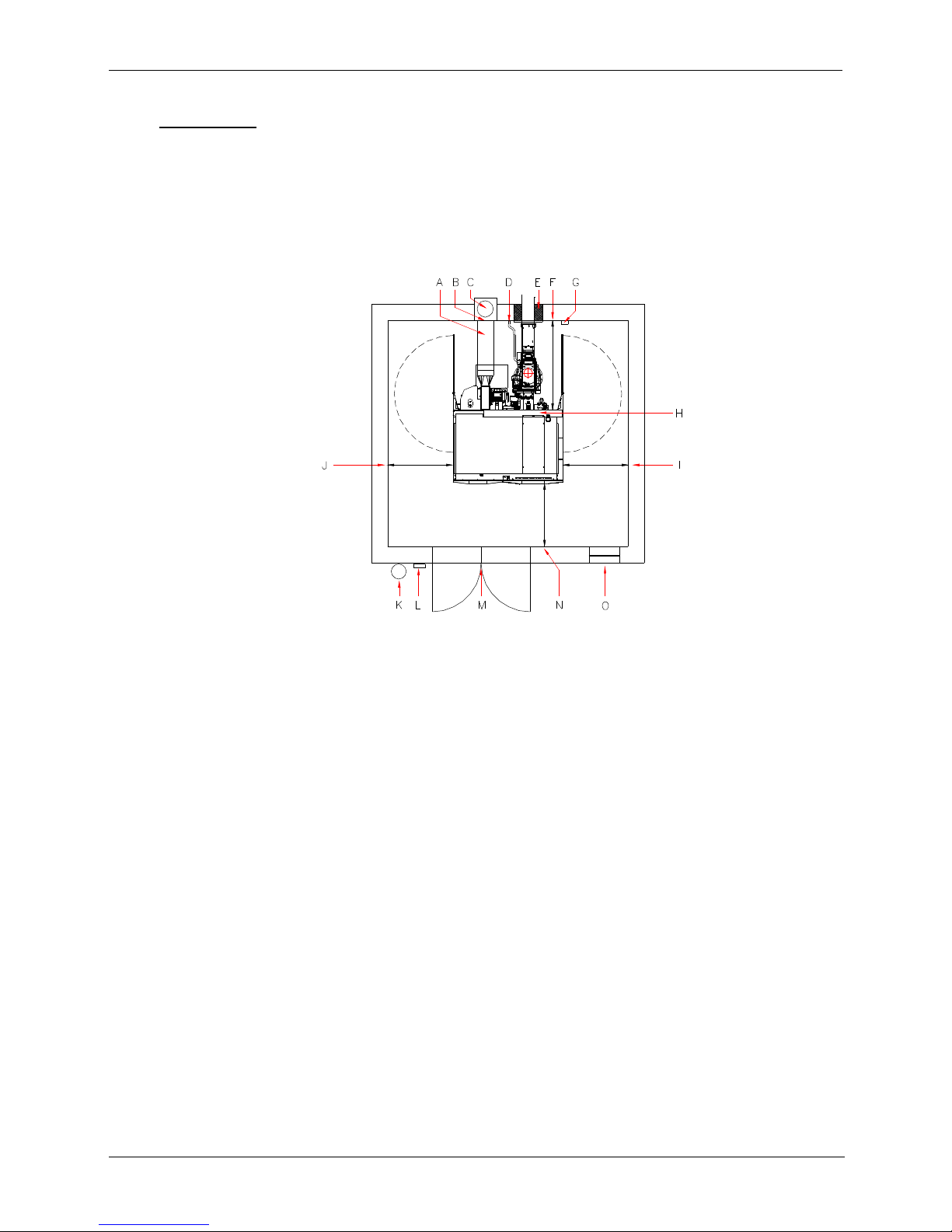
Installation site
Plan for positioning the module(s) as close as possible to the flue to avoid having a long flue
connecting pipe. For servicing purposes and for emptying the ash box, the module should
ideally be accessible from the left or from the rear left. Should it be necessary due to the
circumstances of the site to position the module with its left side against the wall, it is not
possible to empty the ash box. With this configuration, the automatic ash extraction system
has to be installed. In the case of cascade systems with multiple modules, the use of an
automatic ash extraction system is generally advisable.
A → Installation option with draught regulator/pressure-surge compensator in flue
connecting pipe
(As close as possible to junction with flue – observe local regulations – possibility of dust generation)
B → Installation option with flue draught regulator/pressure-surge compensator in flue
(Approx. 50cm below junction with flue – observe local regulations)
C → Flue
(fireclay flue that is insusceptible to damp recommended)
D → Water connection for sprinkler device set to trip at 55°C
(must be connected)
E → Wall aperture
(height 70 mm, width 45 mm)
F → Clearance at rear 1.3m possible
(if clearance at left is at least 1m)
→ 2.3m if clearance at left is less than 1m or if several modules
are placed adjacent to one another
G → Drain for safety valves and temperature relief valve
H → Mains power connection
I → Clearance at right 0cm
possible
(if clearance at left and at rear is at least 1m)
→ 1m if clearance at left is less than 1m
J → Clearance at left 0cm possible
(if clearance at right and at rear is at least 1m)
→ 1m if clearance at right is less than 1m
K → Fire extinguisher
(6 kg gross weight to EN3)
L Emergency off switch
M → Fire door
(Class T30 lockable and self-closing)
N Wall clearance at front at least 1 m
O → Combustion air inlet
(5 cm² per kW output)
PRO Planning and Installation
9
2.3 Flue requirements
The flue must be matched to the system in order to ensure economical
and trouble-free operation.
Important
The system must only be connected to the flue if the flue meets the legal
requirements and the technical specifications. The flue must be matched
to the boiler output and dimensioned in accordance with DIN 4705. In
order to be able to accurately dimension the flue, the calculations must
be based on the flue gas figures. When designing new flues, high
thermal insulation chimneys (DIN 18160 T1) or suitable fireclay flues
that are insusceptible to damp and have general building regulation
approval should be used.
If two or more heating modules are to be connected to a flue, the flue
inspector concerned should always be consulted beforehand. If the flue
inspector has no concerns, the flue must be dimensioned and executed
according to the legal requirements and the technical specifications
based on a calculation by the flue manufacturer.
Note It is always advisable to involve those responsible for
approving the flue system early on in the planning phase.
Flue height The minimum flue height is 5 - 10 m depending on boiler output. The flue
must terminate at least 0.5 m above the highest part of the building. In
the case of flat rooves, the flue must terminate at least 1.5 m above the
surface of the roof.
Flue diameter The flue must be matched to the boiler output. The following details are
guide figures and can be used for planning purposes. However, we
recommend that the flue dimensions are calculated precisely by an
expert.
PRO 175/250 eff. height over 6 m D=250 mm
eff. height under 6 m D=300 mm
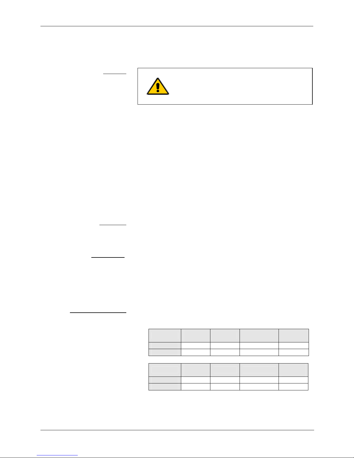
Flue dimensioning data Dimension the flue for rated output.
(Averaged figures with used heat exchanger)
Rated output
Sub-maximum output
Type
Flue gas
temp.
CO2 Mass flow rate
Required
draught
PRO 175
150°C 12.0% 0.144 kg/s 10 pascals
PRO 250
180°C 12.0% 0.194 kg/s 10 pascals
Type
Flue gas
temp.
CO2 Mass flow rate
Required
draught
PRO 175
110°C 10.0% 0.051 kg/s 2 pascals
PRO 250
130°C 10.0% 0.051 kg/s 2 pascals
Use only heat
-
insulated fireclay flues that are
insensitive to damp.
The flue gas temperature may be less than
100°C when the boiler is operating at less
than max. output.

PRO Planning and Installation
10
2.4 Fuel store requirements
Estimating annual requirement Calculation is based on the following annual fuel requirements per
kilowatt of building heat demand:
→ Approx. 2.00 m³ Hardwood woodchips
(m³ per kW/year)
→ Approx. 2.50 m³ Softwood woodchips
(m³ per kW/year)
→ Approx. 0.65 m³ Pellets
(m³ per kW/year)
Storeroom configuration The storeroom should ideally be square in order to achieve the best
possible utilisation by the agitator.
Storeroom ventilation Storerooms and bunkers/hoppers must be ventilated to prevent the
build-up of potentially fatal concentrations of CO. The air vents must
connect to the outside and ensure that there is circulation of air between
the storeroom and the outside. If the natural convection is insufficient,
adequate technical means must be provided.
If the filler pipes do not open to the outside, ventilation via a separate air
vent must be provided. Measures must be taken to ensure that rainwater
cannot enter the storeroom through the air vents.
Rooms containing fuel storage hoppers made of air-permeable fabric
must have an air vent opening to the outside.
An air vent cross-sectional area of 200 cm² is sufficient.
For storerooms up to 30 t capacity, the requirements are satisfied if:
• the filler pipes open to the outside; ventilation can be by means of
vented filler caps;
• the diameter of the vent pipes is at least 90 mm;
• the net clear cross-sectional area of the air vents in the case of
filler/vent pipes up to 2m in length is at least 40 cm² and for pipes
over 2m long at least 60 cm²; 2x filler cap = 60 cm²;
For storerooms over 30 t capacity, the requirements are satisfied if:
• either a combination of natural and mechanically assisted
ventilation based on CO sensing is used or a state-of-the-art forced
ventilation system for elimination of the CO hazard is installed.
Storeroom filling Woodchips are usually delivered by a tipper lorry. A surfaced access to
the storeroom is required. Ideally, the storeroom should be located on
the outside wall and filled through a door. To prevent damage to the
agitator when the woodchips are being shovelled into the storeroom by a
front loader, the bottom edge of the filler door should be at least 30 - 40
cm above the lowest point of the agitator arms. If the fuel storeroom is
filled by a tanker truck using a compressed-air delivery system, the filler
pipes must be earthed. With this method of filling, make sure the
storeroom is dust-sealed.

PRO Planning and Installation
11
Access doors/boarding Above-ground fuel stores must be provided with a lockable door or hatch
(outward-opening) with an opening area of at least 1.80 m². So that the
fuel cannot run out if the fuel store is opened by mistake, the inside of the
access door/hatch opening must be covered with boarding (which must be
removable from the outside). Due to the risk of injury when the system is
in operation, access doors/hatches must be lockable and kept locked
when the system is in operation. Attached to the access door there must
be a warning sign indicating the dangers of entering the storeroom and
offering safety guidance.
Electrical installations Agitator
Electrical equipment is prohibited in the fuel storeroom.
Overhead filler auger
The drive motor and the necessary electrics must be installed outside the
storeroom.
Filler set The filler pipes must be earthed.
At least 2 filler pipes must be installed. Minimum separation 0.5m –
maximum separation 1.5m
Structural requirements The enclosing walls must be capable of withstanding the possible static
loads created by the stored fuel and the pressure when filling the fuel
store.
Damp-proofing The fuel must be protected against contact with water or damp
floors/walls. The storeroom must remain dry all year round. If there is a
risk of temporarily damp walls, fitting a back-ventilated facing to the walls
and lining them with wooden material may be required.
Floor boarding If fuelling the system with pellets, a boarded or concrete floor is absolutely
essential. If the system is to be fuelled exclusively with woodchips, the
floor can be covered with dry logs instead of boards.
PRO Planning and Installation
12
Filler auger The drive motor and the necessary electrics must be installed outside the
storeroom. A lockable emergency off switch with motor cut-out function
must be installed in the immediate vicinity of the filler shaft. Storeroom
doors must be provided with a door switch which cuts off the power supply
to the filler auger when the door is opened. The filler shaft must be
covered by a grate.
Wall opening The tables of dimensions below detail the measurements for positioning
the wall opening according to the length of the auger.
Note All agitator fuel outfeed systems are supplied with a fuel outfeed unit, an
auger trough and the relevant agitator.
Standard outfeed system:
Agitator Dimension A Dimension B
3.0 m Approx. 49 cm Approx. 73 cm
3.5 m Approx. 49 cm Approx. 76 cm
4.0 m Approx. 49 cm Approx. 79 cm
4.5 m Approx. 49 cm Approx. 82 cm
5.0 m Approx. 49 cm Approx. 85 cm
Standard outfeed system + additional 55cm auger trough:
Agitator Dimension A Dimension B
3.0 m Approx. 102 cm Approx. 62 cm
3.5 m Approx. 102 cm Approx. 65 cm
4.0 m Approx. 102 cm Approx. 68 cm
4.5 m Approx. 102 cm Approx. 71 cm
5.0 m Approx. 102 cm Approx. 74 cm
Standard outfeed system + additional 110cm auger trough:
Agitator Dimension A Dimension B
3.0 m Approx. 156 cm Approx. 53 cm
3.5 m Approx. 156 cm Approx. 56 cm
4.0 m Approx. 156 cm Approx. 59 cm
4.5 m Approx. 156 cm Approx. 62 cm
5.0 m Approx. 156 cm Approx. 65 cm
Standard outfeed system + additional 220cm auger trough:
Agitator Dimension A Dimension B
3.0 m Approx. 265 cm Approx. 42 cm
3.5 m Approx. 265 cm Approx. 45 cm
4.0 m Approx. 265 cm Approx. 48 cm
4.5 m Approx. 265 cm Approx. 51 cm
5.0 m Approx. 265 cm Approx. 54 cm
Wall opening
Width 450 mm
Height 700 mm
PRO Planning and Installation
13
2.5 Planning examples for the fuel store
Important → For systems fuelled by pellets, filler connections must also be provided.
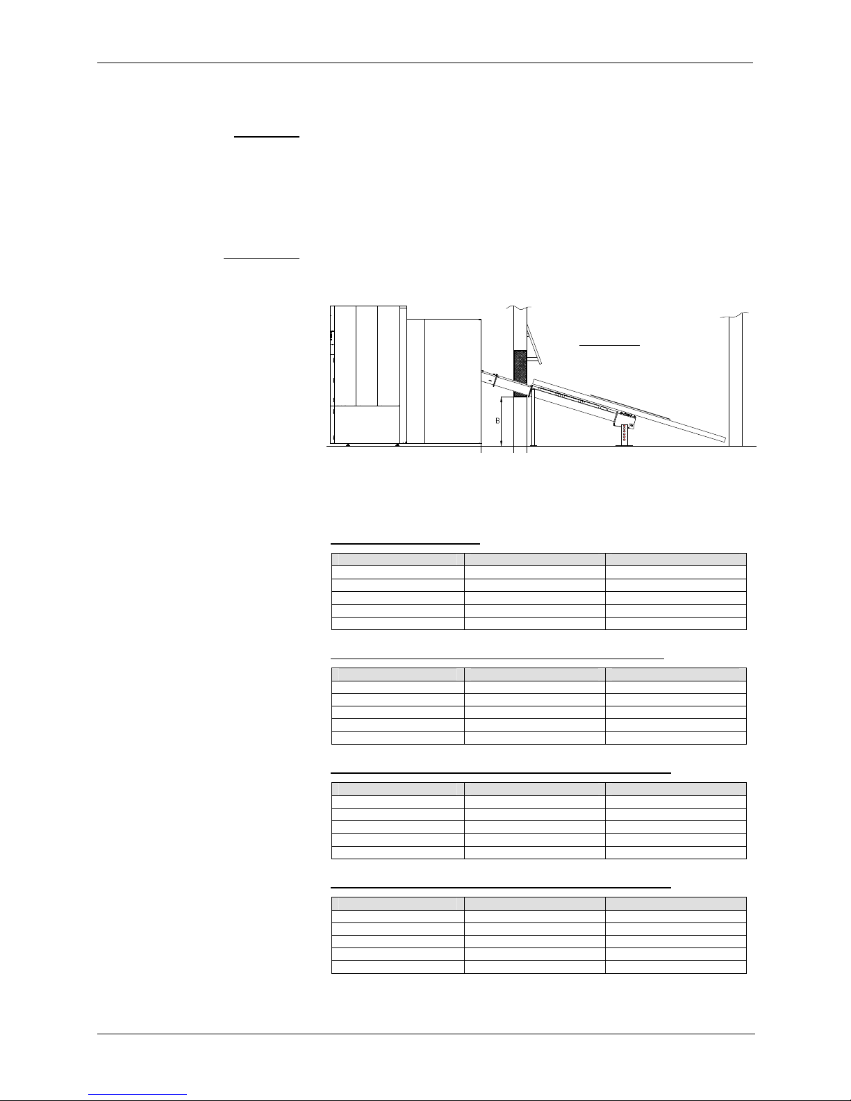
Planning example 1 The storeroom is alongside or behind the boiler room and can be filled
through a door by a front loader. The maximum length of the outfeed
system including agitator is 7 m.
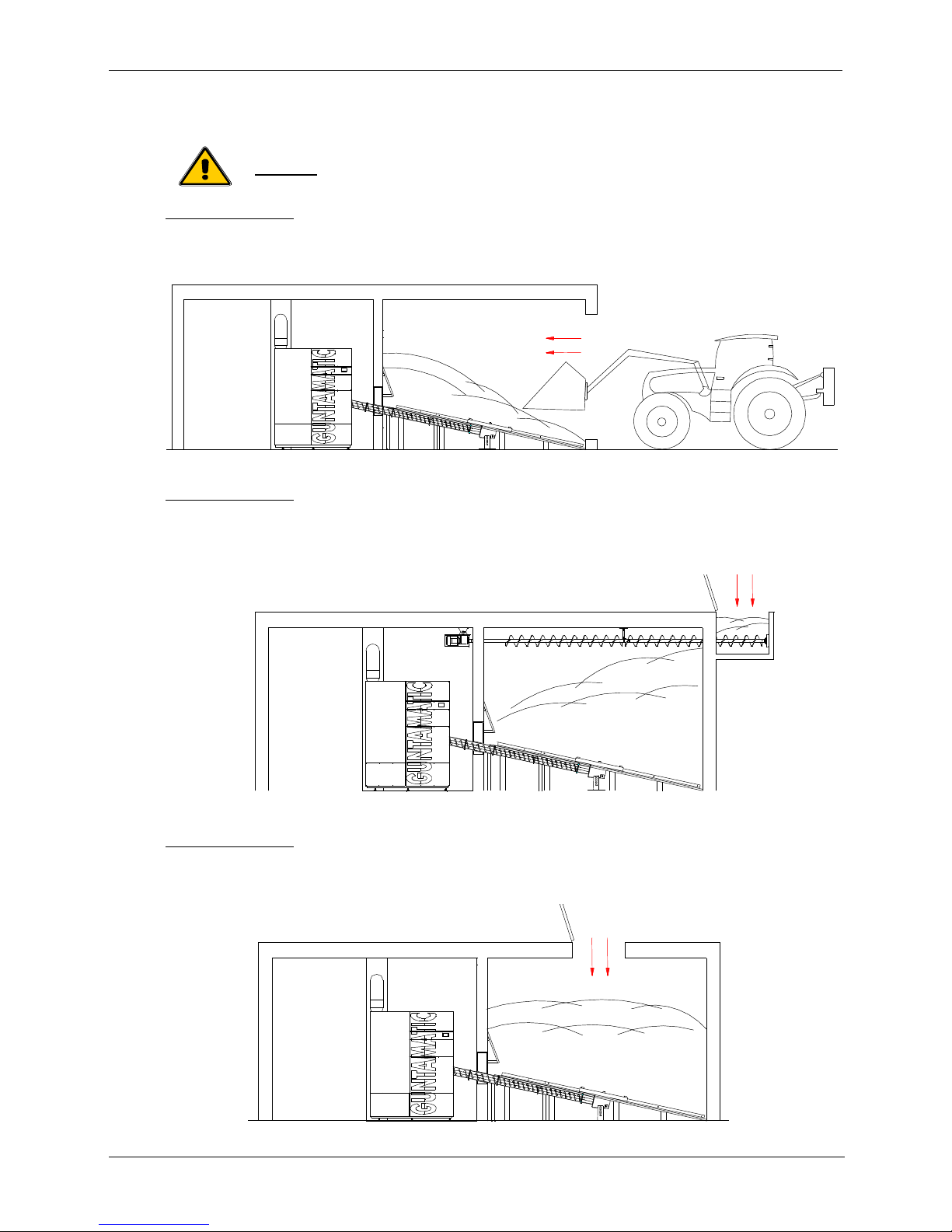
Planning example 2 The storeroom is alongside or behind the boiler room and is filled by an
overhead filler auger from a filler shaft. Available filler auger lengths: 3 m,
4 m, 5 m, 6 m or 7 m
(non extendable).
Planning example 3 The storeroom is alongside or behind the boiler room and the fuel is
brought in via a shaft in the storeroom ceiling. The maximum length of the
outfeed system is 7 m.
PRO Planning and Installation
14
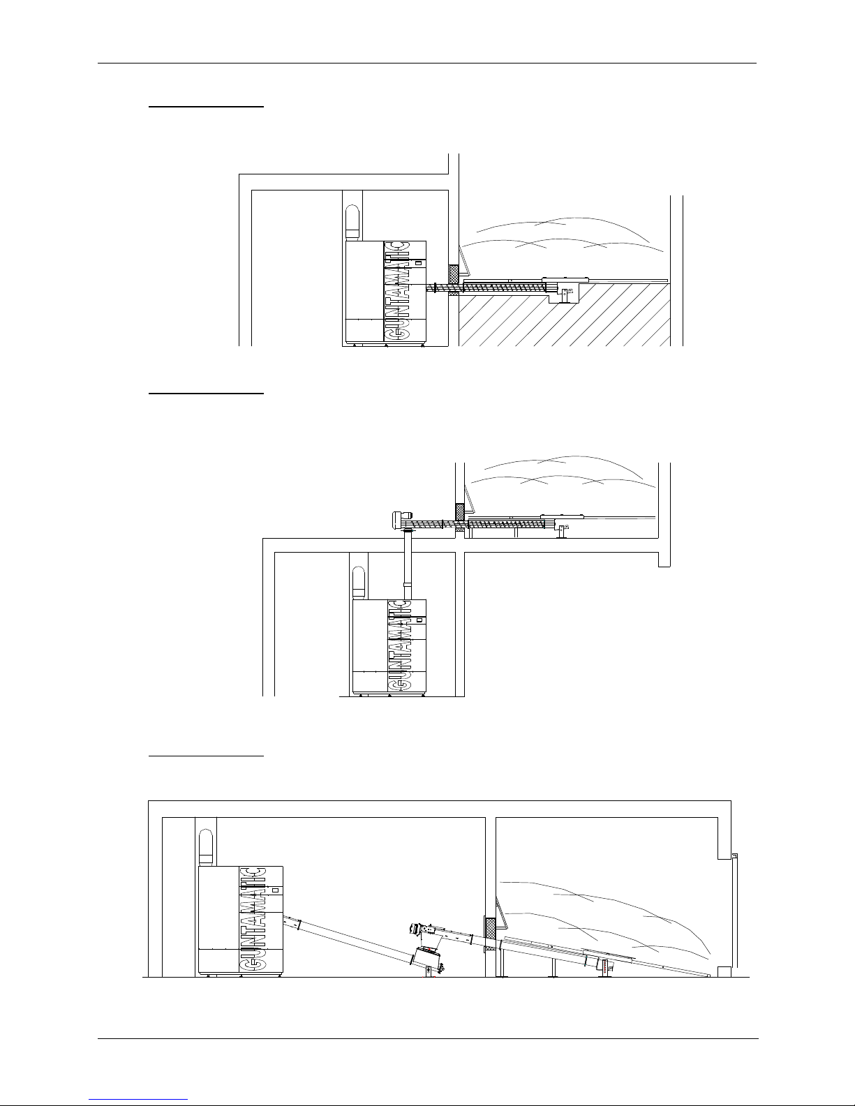
Planning example 4 The storeroom is alongside or behind the boiler room. The fuel outfeed
from the storeroom is via a horizontally mounted agitator.
Planning example 5 The storeroom is above the boiler room. The fuel is carried via a
downpipe through the ceiling to the boiler.
Planning example 6 Outfeed system with transfer unit and feeder auger. The maximum length
of the feeder auger is 7 m.

PRO Planning and Installation
15
2.6 Delivery
The boiler system is delivered packed in multiple sections wrapped in
foil. Please check that the delivery is complete according to the delivery
note and in perfect condition.
Deficiencies Please make a note of the deficiencies identified directly on the delivery
note and contact the supplier, heating installer or our Customer Service.
2.7 Carrying to installation site
The individual system components are delivered on wooden pallets and
can be lifted and carried to the installation site using a pallet truck.
2.8 Positioning and aligning the boiler
Keep to the minimum wall clearances specified by the system planner
and manufacturer. If important details are missing, please ask our
Technical Support. Position the system as close as possible to the flue
to avoid having a long flue connecting pipe. The system must be
accessible from the left or right side.
Clearance at left → 0cm possible if clearance at right and at rear is at least 1m
→ 1m if clearance at right is less than 1m
Clearance at right → 0cm possible if clearance at left and at rear is at least 1m
→ 1m if clearance at left is less than 1m
Clearance at front → at least 1 m
Clearance at rear → 0cm possible if clearance at left is at least 1m
→ 1m if clearance at left is less than 1m or if several modules are placed
adjacent to one another
Floor clearance Set the clearance between the boiler base and the floor
to the required minimum of 35 mm by unscrewing the adjustable feet on
the boiler base.
Set the boiler at a slant Unscrew the rear adjustable feet slightly further so that the boiler is
slightly higher at the rear. That will allow the air inside the boiler to
escape easily when the system is filled.
PRO Planning and Installation
16
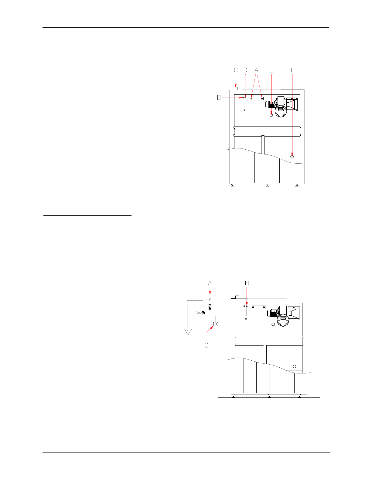
2.9 Plumbing connections
A → Temperature-relief heat exchanger, ¾"
B → Boiler sensor, STL
C → Heating flow, 2"
D → Sensor for temp. relief valve, ½"
E → Heating return, 2"
(run pipe upwards)
F → Drain, 2"
Temperature-relief heat exchanger The maximum permissible boiler operating temperature is 110°C. In order
to prevent the maximum allowable operating temperature being
exceeded, connection of a temperature-relief valve conforming to Austrian
standard ÖNORM 8131 and DIN 4751 and with a response temperature
of 95°C is required. The supply pressure must be at least 2 bar but no
more than 6 bar.
A → Cold water supply for
Temperature-relief heat exchanger
B → Sensor for temp. relief valve, ½"
C → Temp. relief valve, 95°C
 Loading...