

Guntamatic POWERCHIP 20, POWERCHIP 30, POWERCHIP 75, POWERCHIP 100, POWERCORN 50 Special Planning And Installation
...Page 1
Woodchip boiler englisch
POWERCHIP
/ POWERCORN 50 Special
Planning and installation
PH-01
EN-B31-009-V17-0815
Page 2

2
Information on this documentation
BS-01
Please read through this documentation carefully.
It is intended as a reference document and contains important
information on the design, safety, operation, maintenance and
care of your heating system.
We are always looking to improve our products and
documentation. Any ideas and suggestions you may have will
be gratefully received.
GUNTAMATIC Heiztechnik GmbH
Bruck 7
A-4722 PEUERBACH
Tel: 0043 (0) 7276 / 2441-0
Fax: 0043 (0) 7276 / 3031
Email: office@guntamatic.com
It is important that you pay particular attention
to the safety issues highlighted in the text by
these symbols.
The entire contents of this document are the property of
GUNTAMATIC and therefore protected by copyright.
Reproduction of any kind, communication to third parties by any
means or use for purposes other than those intended without
the written consent of the owner is prohibited.
Subject to printing errors and technical amendments.
Page 3

3
Contents
PH-01
Page
1 Introduction ............................................................................4
1.1 Safety instructions 4
1.2 Guarantee and liability 4
1.3 Commissioning 4
1.4 Site requirements 4
2 PLANING .................................................................................5
2.1 Fire safety 5
2.2 Minimum fire safety requirements 6
2.3 Boiler room requirements 8
2.4 Flue requirements 10
2.5 Flue draught regulator and pressure-surge compensator 11
2.6 Fuel store requirements 12
2.7 Examples for Planning 15
2.8 Automatically ash System 17
2.9 Heating circuit Rules 19
3 Construction.........................................................................21
3.1 Delivery 21
3.2 Carrying to installation site 21
3.3 Positioning and aligning the boiler 21
3.4 Fuel out feed installation 22
3.5 Plumbing connections 26
3.6 Filling and bleeding the system 29
3.7 Connecting the flue 30
4 Electrical connections .........................................................31
4.1 Heating system electrical connections 33
5 Final checks..........................................................................34
6 Standards / Regulations ......................................................35
7 Plumbing diagrams..............................................................36
7.1 Backup Memory HP0 36
8 Technical data ......................................................................54
8.1 Powerchip 20/30 and 40/50 54
8.2 Powerchip 75 and 100 55
8.3 Powercorn 50 Special 56
8.4 Removal 57
8.5 Celling filling spiral 59
Page 4

4
1 Introduction
BS-01
1.1 Safety instructions
GUNTAMATIC heating systems represent state-of-the-art
technology and meet all applicable safety regulations. Incorrect
installation can endanger life and limb. Heating boilers are
combustion systems and are potentially dangerous if handled
incorrectly. Installation, commissioning and servicing must,
therefore, only be carried out by adequately qualified
technicians observing all regulations and the manufacturer's
instructions.
1.2 Guarantee and liability
The manufacturer's guarantee is subject to correct installation
and commissioning of the heating system. Defects and
damage caused by incorrect installation, commissioning or
operation are not covered by the guarantee. To ensure that the
system functions as intended, the manufacturer's instructions
must be followed. Furthermore, only genuine replacement
parts or parts explicitly approved by the manufacturer may be
fitted to the system.
1.3 Commissioning
Commissioning of the boiler must be carried out by an
authorised GUNTAMATIC specialist or other qualified persons.
They will check whether the system has been installed
according to the plans, adjust the system settings as required
and explain to the system operator how to use the heating
system.
1.4 Site requirements
When establishing the site requirements, it is absolutely
essential to take account of the locally applicable planning,
building and implementation regulations and the dimensional
specifications in the fitting guidelines, installation examples and
technical data. Compliance with the locally applicable
regulations and the correct implementation of the measures
required on site are solely the responsibility of the system
owner and are a requirement of the manufacturer's guarantee.
GUNTAMATIC provides no guarantee of any kind for any type
of site work. Without making any claims as to completeness or
non-applicability of official requirements, we recommend the
following specifications based on the Austrian Guidelines pr
TRVB H 118:
Page 5
5
2 Planning
01
2.1 Fire safety
BS-01
The fire security instroductions are obligatory needed
on the construction place
The Compliance from counties ore states fire security
law is obligatory and stands higher then the
GUNTAMATIC fire security instruction
Austria State legislation of the federal states
Technical Directive on Preventative Fire Safety (pr TRVB H118)
Germany Standard boiler regulations (M-FeuVO)
Hessen and Saarland – in these states §16 FeuVO Hessen applies
Switzerland Fire safety regulations
(www.vkf.ch)
any other exporting countries Any fire safety office
You have to follow you specific country fire safety
rules obligatory. Your country safety rules are higher
then our GUNTAMATIC minimum rules.
If there are no specific fire security rules in your
country, you have to follow the GUNTAMATIC
introductions
Page 6
6
2.2 Minimum fire safety requirements
PH-01
Boiler room Floor of concrete construction, either bare or tiled. All materials
for floor, walls and ceiling must be fire-resistant to F60/REI60
rating.
Boiler rooms door: The Boiler room’s door also might close
single handed and it has to be possible to close off the door.
Connecting doors to the fuel storeroom must also be Class
T30/EI230-C fire doors, self-closing and lockable. There must
be no direct connection to rooms in which flammable gases or
liquids are stored.
Sprinkler: Connected to the outfeed unit there must be a
sprinkler device set to trip at 55°C. With storeroom volumes up
to 50 m³, this is used instead of the temperature monitor. When
the sprinkler is triggered, the sloping outfeed auger enclosure –
which also serves as a burn-back inhibiting device – is
completely flooded. The quantity of water required to do so is
at least 20 litres. If the temperature drops back below 55°C, the
flooding is stopped.
The sprinkler system must be
connected on all systems regardless
of local regulations!
Fuel storeroom The same minimum fire safety requirements apply as for the
boiler room.
Storeroom doors/hatches: Storeroom doors/hatches must be
fire safe to Class T30/EI230-C, self-closing and lockable. There
must be a warning sign carrying the message "Do not enter
when feeder system is running" attached to the storeroom
door/hatch.
> 50 m³
TÜB - Temperature monitor: If it is possible to store 50 m³ of
fuel or more, a temperature monitor connected to a warning
device must be installed in the fuel storeroom at the point
where the fuel conveyor exits the fuel store and enters the
boiler room. The warning device must be triggered when the
temperature exceeds 70°C. Because of the sprinkler system,
the temperature monitor on the outfeed auger is not required
for storerooms with a capacity of less than 50 m³.
> 50 m³
HLE - Manual fire extinguisher: If 50 m³ of fuel or more can
be stored, a manually operated fire extinguishing facility must
be installed. It must be protected against freezing and
connected to a pressurised water pipe (DN20 conduit). The
discharge point must be located directly above where the fuel
outfeed channel exits the storeroom. The fire extinguishing
facility must be identified by a sign carrying the inscription
"Fuel storeroom fire extinguisher".
Page 7

7
SLE - Automatic fire extinguishing facility:
For storage rooms in farm building it is possible to dispense
with a F90 / REI90 cladding for fuel storage and if the fire
compartment is less than 500 sq meters . The fuel but
separately ( wooden planking ) must be stored on other goods
. If furthermore a firewall to a residential wing before, so an
automatic extinguishing device ( SLE ) is also required.
This extinguishing equipment must be connected either directly
to a pressurized water supply or to a water -supply container .
The amount of water to need three times the volume of the
loading device shall be not less than 20 liters .
Inspection covers: There must be a lockable F90-class
inspection hatch above the fuel out feed channel.
Services area: For storerooms in the services area, it is
possible to dispense with F90/REI90 jacketing of the fuel store.
The fuel must be stored separately (wooden boarding) from
other materials and the fire containment zone must be less
than 500 m².
Filler pipes: Filler pipes through rooms where there is a fire
risk must be provided with Class F90/REI90 cladding.
Page 8

8
2.3 Boiler room requirements
PH-01
Minimum room height
PH 30 / 50 / 50 S ideal solution
H 225 cm
1)
possible
H 210 cm
PH 75 / 100 ideal solution
H 240 cm
1)
possible
H 230 cm
1)
= Mindestraumhöhe bei abgeschraubtem Wärmetauscherdeckel
Minimum room size
PH 30 / 50
B 240 cm x
2)
T 230 cm
(
3)
T 240 cm)
PH 75 / 100 / 50 S
B 270 cm x
2)
T 230 cm
(
3)
T 240 cm)
2)
T = The room with boiler´s bodies front seeing from behind
3)
= Minimum size from the automatic ash suction system
Clear access opening
PH 30 / 504) ideal
B 120 cm x H 185 cm
5)
possible
B 80 cm x H 170 cm
7)
possible
B 75 cm x H 165 cm
PH 75 / 100 / 50 S4) ideal
B 195 cm x H 210 cm
(
6)
185 cm)
5)
possible
B 100 cm x H 190 cm
(
6)
170 cm)
7)
possible
B 90 cm x H 180 cm
4)
Contribution from the ready constructed boiler on the pallet
5)
Constribution without Stoker, cleaning unity and pallet
6)
minimum height of boiler type powercorn 50 S
7)
dimensions with additional to point 5) with unrigged cover panel
Combustion air supply The pressure in the boiler room must not be less than 3 Pa
(0.3 mm H2O). The air vents for boiler rooms must have a
clear, net cross-sectional area of at least 200 cm² and must not
be sealable. With combustion boiler systems with a fuel heat
output upwards of 50 kW, the net, clear cross-sectional area
must be increased to at least 5 cm² per kW rated output
according to the combustion air requirement of the boiler
system. The air supply ducting must connect directly to the
outside and if the ducting passes through other rooms, it must
be jacketed to Class F90/REI90. On the outside of the building,
air vents must be covered by a protective grille with a mesh
size of > 5 mm. The supply of combustion air should, if
possible, enter at floor level in order to prevent cooling of the
boiler room.
Electrical installation The lighting and the electrical wiring in the boiler room must be
permanently installed. There must be a clearly marked
emergency off switch in an easily accessible position outside
the boiler room, close to the boiler-room door.
The line connector 400 VAC, 50 Hz, 13 A is needed.
Fire extinguisher A hand-held fire extinguisher (6kg gross weight, EN3) must be
mounted outside the boiler room near the boiler-room door.
Protection against freezing
The boiler room, pipes carrying water and any district heating
pipes must be protected against freezing.
Page 9
9
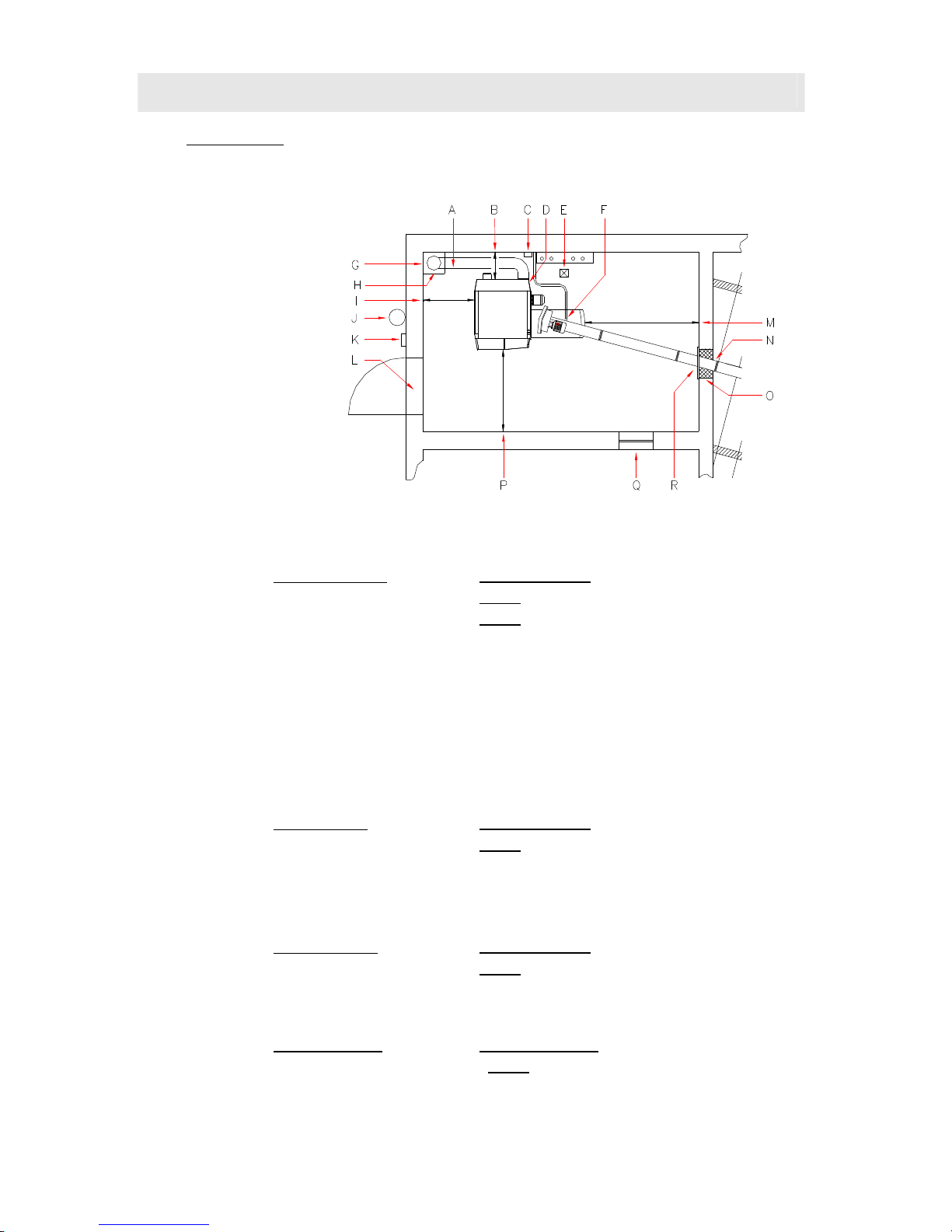
Installation site You have to plan the furnace in the near of the chimney to avoid a long
flue pipe.
A →
Integration version of Energy saving draft regulator with Ex flap and with fire tube
respect the local fire security rules- dust information possible
B →
BEHIND distance
ideal
70 cm minimum
possible
50 cm
without Ash suction system
60 cm
with Ash suction system
C →
The discharge for overheating
D →
Line Connector 400V 13A
E →
Drain
F →
Sparger complex
G →
flue
wet non- sensitive chamotte-flue advised
H →
installation variant energy-saving damper with explosion damper in the flue
c
a. 50 cm under the flue – please follow the local laws
I →
LEFT distance
ideal
70 cm minimum
possible
40 cm
J →
fire extinguisher
6 kg filling weight EN3
K →
escape switcher
L →
fireproof door
T30 / EI230-C lockable and self depended
M →
RIGHT distance
ideal
70 cm minimum
possible
40 cm
N →
HLE manual release arc control device
O →
Mauerdurchbruch
Höhe 70 cm / Breite 45 cm
P →
AHEAD distance
ideal
100 cm minimum
possible
80 cm
Q →
Air combustion supply
R →
TÜB Warning device for to heaters spiral’s temperature
Page 10
10
2.4 Flue requirements
PH-01
Use heat-insulated fireclay flues that are
insensitive to damp.
The flue gas temperature can be less
than 100°C.
The system must only be connected to the flue if the flue
meets the legal requirements and the technical specifications.
The flue must be matched to the boiler output and
dimensioned in accordance with DIN 4705. In order to be able
to accurately dimension the flue, the calculations must be
based on the flue gas figures. When designing new flues, high
thermal insulation chimneys (DIN 18160 T1 heat transmission
resistance group I) or suitable fireclay flues that are
insusceptible to damp and have general building regulation
approval should be used. It is advisable to involve those
responsible for approving the flue system early on in the
planning phase.
Flue height The minimum flue height is 5 - 10 m depending on boiler
output. The flue must terminate at least 0.5 m above the
highest part of the building. In the case of flat rooves, the flue
must terminate at least 1.5 m above the surface of the roof.
Flue diameter The flue hast to adjust on the fire power. The following datas
are approximate values and could be used for planning. We
recommend to calculate the flue by a professional.
PH 30 / 50 / (PC 50-S)
PH 75 / (100)
eff. high above 6 m D = 160 (180) mm
eff. high under 6 m D = 180 (200) mm
eff. high above 6 m D = 220 (250) mm
eff. high under 6 m D = 250 (250) mm
Flue dimensioning data Dimension the flue for rated output!
(Averaged figures with used heat exchanger)
Rated output:
Type Flue gas CO2 Mass flow rate
Required
draught
PH 30 180°C 12,5% 0,025 kg/s 15 Pascal
PH 50 190°C 13,0% 0,040 kg/s 15 Pascal
PC 50-S 185°C 12,5% 0,040 kg/s 15 Pascal
PH 75 180°C 12,5% 0,065 kg/s 15 Pascal
PH100 195°C 12,5% 0,082 kg/s 15 Pascal
Sub-maximum output:
Type Flue gas CO2 Mass flow rate
Required
draught
PH 30 130°C 9,5% 0,010 kg/s 2 Pascal
PH 50 145°C 10,0% 0,015 kg/s 2 Pascal
PC 50-S 140°C 9,5% 0,015 kg/s 2 Pascal
PH 75 140°C 9,5% 0,020 kg/s 2 Pascal
PH100 150°C 10,5% 0,025 kg/s 2 Pascal
Page 11
11
2.5 Flue draught regulator and pressure-surge compensator
BS-01
Fitting an energy-saving flue draught
regulator/pressure-surge compensator
(Class RE) is absolutely imperative.
The flue draught should not differ by more than +/- 3 pascals
from the figure specified in the flue dimensioning data. If the
flue draught cannot be reduced to the required figure, either a
larger draught regulator should be fitted or an additional flue
baffle fitted between the flue and the draught regulator.
Purpose
• To ventilate the flue when the system is not in operation
• To compensate for pressure surges
• To regulate and limit the flue draught
Fitting requirement The energy-saving flue draught regulator must be fitted in
accordance with the local regulations, preferably in the flue
approx. 0.5 m below the point where the flue connecting pipe
joins or alternatively in the flue connecting pipe close to its
junction with the flue.
Flue draught setting
• Adjusting the flue draught is only of any use at
outside temperatures below +5°C.
•
The system must have been in operation for at least an hour
• Ensure there is sufficient demand for heat for the boiler to
be run at rated output for at least 15 minutes
• Measure the flue draught between the boiler and the flue
draught regulator (distance of measuring point from boiler
ideally 3 x flue diameter from connection between boiler
and flue connecting pipe).
Too much flue draught
May cause the flue gas temperature to increase
and accelerate combustion as a result. Poor
boiler output adjustability, increased dust
discharge and malfunctions can result.
Too little flue draught
Performance problems, incomplete combustion
and malfunctions when operating below rated
output can result.
Page 12

12
2.6 Fuel store requirements
PH-01
Please note:
the specific national rules for your fuel store
(for example. ÖNORM M7137, VDI 3464,..
.) are strictly
adhered blindly
Annual demand for fuel store The fuel store should be able to pick up the stock for a year .
Per 1 kw building heat is expected with the following annual
fuel demand .
→ per 1 kW/Year ca. 2,00 m³ = ca. 550 kg
beech
→ per 1 kW/Year ca. 2,50 m³ = ca. 500 kg
spruce
→ per 1 kW/Year ca. 0,65 m³ = ca. 450 kg
Pellets
→ per 1 kW/Year ca. 0,75 m³ = ca. 550 kg
Energycorn
→ per 1 kW/Year ca. 4,30 m³ = ca. 470 kg
Miscanthus
Fuel store arrangement You have to built your Storeroom in a quadratic frame, to use
the filling spiral optimally.
Fuel store air sparging To avoid an high perilous Co² consentration you have to lift the
store and Broiler room.The opening for the lifting might
discharge into the atmosphere. There must be an air change
between the Storeroom and the ambient atmosphere. If the
natural thermal isnt´t enough you have to take technical
measures.
If the filling stubs (the openings) discharges not into the
atmosphere you have to lift it with another lifting opening. you
have to be careful, that there is no rainwater into the storeroom
from the filfting opening. The construction site from the
permeable to air storage container might have a port in to the
atmosphere. A ventilator shifts from 200cm² is enough.
Up to 30 t storage volume the requirement is prepossessed, if:
• The filling stub (opening) is leading into atmosphere for
minimum 2 caps with an air inlet
• The diameter from 2 ventilation pipes is per pipe
minimum 90 mm
• The ventilator shift from the exhaust port from both
Ventilation pipes from 2 m minimum 40 cm² and must be
higher then a lenghth from 2 me but minimum 60 cm ².
INFO: The whole ventilation shift from 2 caps from our
filling sets is 60 cm².
Over 30 t storage volume the requirements
• a combination between natural and manual lifting, based
on a Co² Sensor. If there is no natural lifting you have to
install forced ventilation- in cas of a high Co²
Concentration ventilation is lifting automatically.
Page 13

13
Storeroom filling The hackchips are delivered by a tip truck. A fired drive at your
house to the storeroom is needed, if it´s possible. Ideally the
storeroom is on the external wall and is reachable and reflable
form the gate. To avoid damages on the agiator during
insertion of the hack chips, you shall fill the storeroom with a
front loader. The filling opening should be 30 up to 40 cm
minimum higher than the deepest point of the springroom. If
the fuel storeage room is pneumatic filled through a pump
carrage. In this kind of fillimg you have to care if there is a
dustproff speration.
Access doors/hatches Above-ground fuel stores must be provided with a door or
hatch that opens outwards. So that the fuel cannot run out if
the fuel store is opened by mistake, the inside of the access
door/hatch opening must be covered with boarding (which
must be removable from the outside). During to the risk of
injury when the system is in operation, access doors/hatches
must be lockable and kept locked when the system is in
operation. There must be a warning sign carrying the message
"Do not enter when feeder system is running" attached to the
access door/hatch.
Electric Installation Electronic installation in the fuel stores are not allowed
Filler couplings must be single ended.
Structural requirements The enclosing walls must be capable of withstanding the
possible static loads created by the fuel and the pressure when
filling the fuel store.
Damp-proofing The fuel must be protected against contact with water or damp
floors/walls. The storeroom must remain dry all year round. If
there is a risk of temporarily damp walls, fitting a backventilated facing to the walls and lining them with wooden
material may be required.
Doors Aboveground fuel stores must be accessible via a door
(lockable) of at least 1,80 m² cross-section to the outside,
inside and planked removable from the outside, so that the fuel
can not fall out when erroneous opening the door.
floor planking For operation with heating corn or pellets, a ground-planking or
a concrete floor is absolutely necessary. If it is only running by
hack chips, dry wood chips may be introduced instead of the
soil.
Page 14
14
Celling agitator The drive motor and the necessary electrical installations must
be installed outside of the storage room. A lockable emergency
stop switch with motor protection must be installed in the
immediate vicinity of the charging slot switches, which
interrupts the power supply of the auger when opening the
door, secured. The filling shaft must be secured with a grating.
.
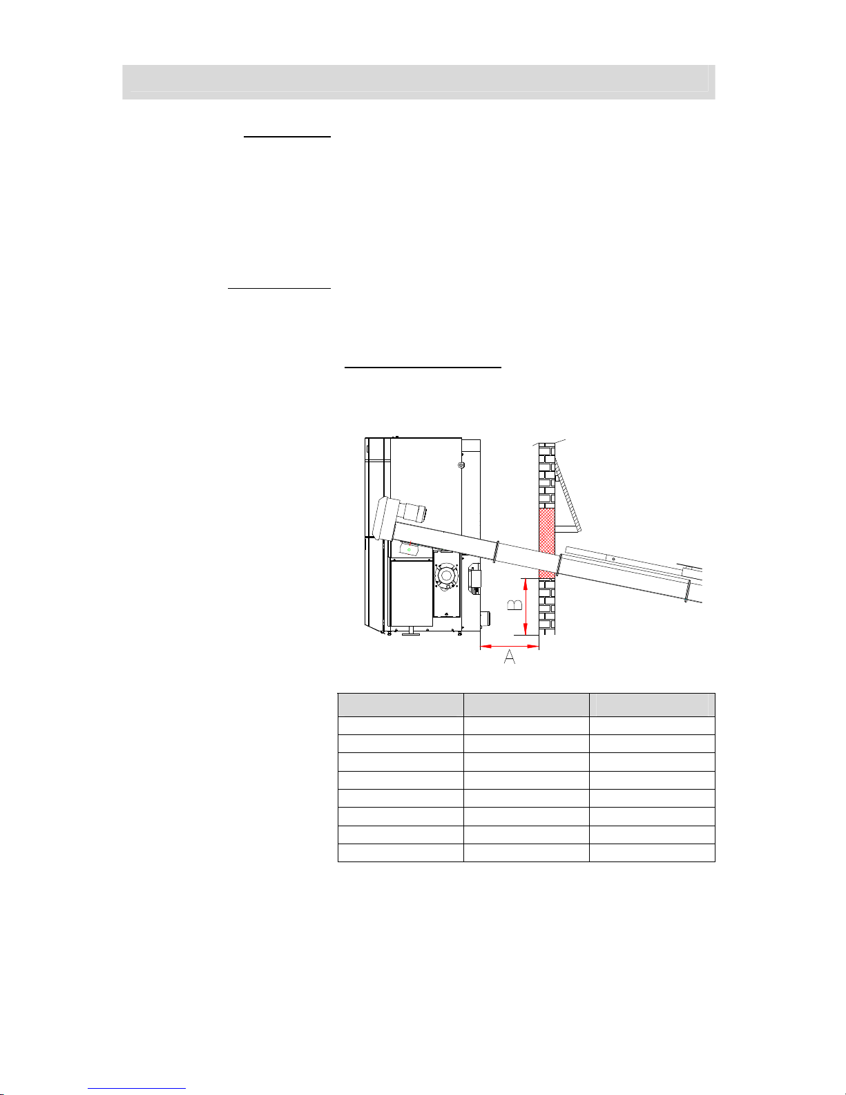
wall breakthrough The following measure table shows the measure for positioning
from the wall breakthrough. The measures apply to the serial
production.
serial production = discharge unity + 0,55 m hutch and agitator
Measure wall breakthrough
wide 45 cm
length 70 cm
Agitator Measure A Measure B
1,5 m 50 cm 37 cm
2,0 m 50 cm 41 cm
2,5 m 50 cm 44 cm
3,0 m 50 cm 47 cm
3,5 m 50 cm 50 cm
4,0 m 50 cm 53 cm
4,5 m 50 cm 54 cm
5,0 m 50 cm 55 cm
Page 15
15
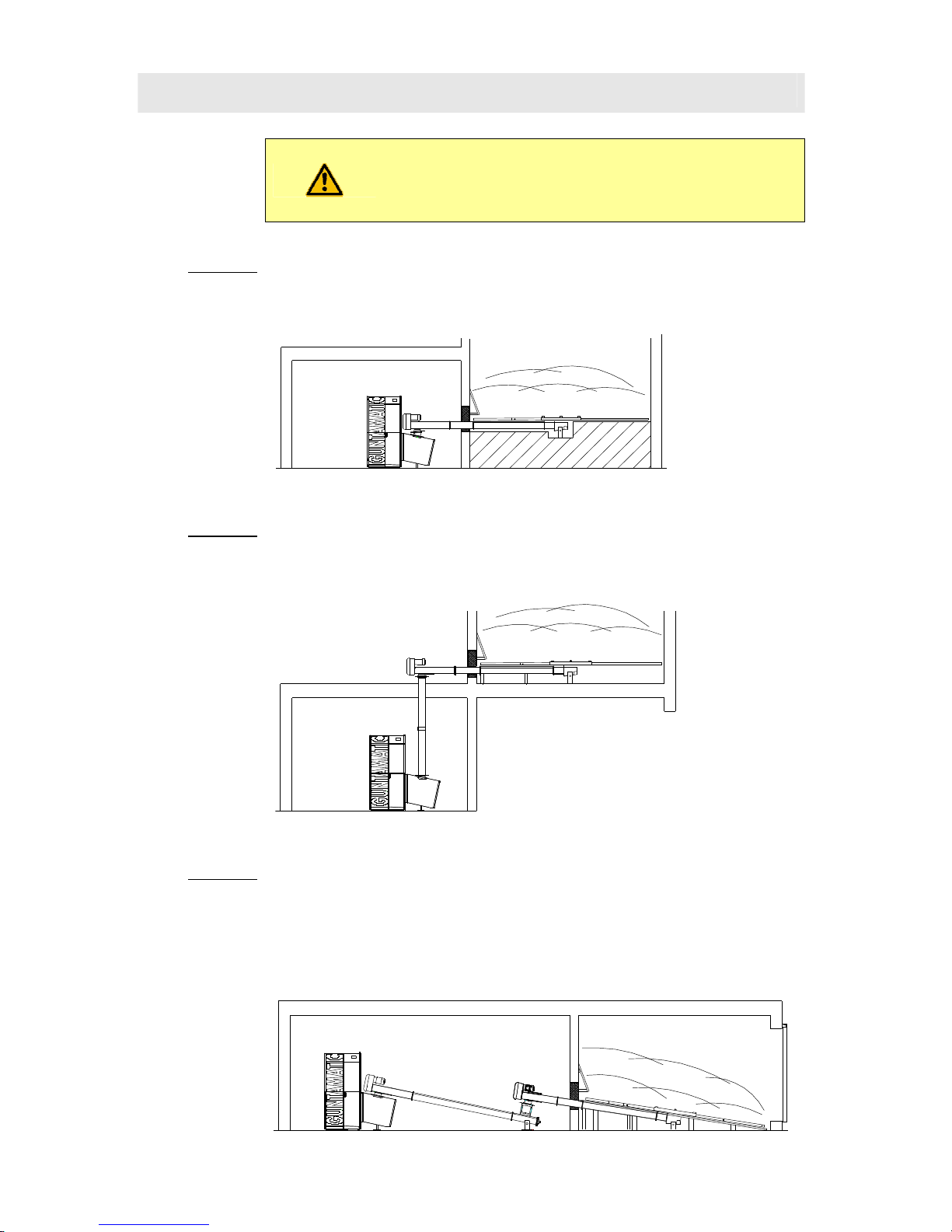
2.7 Examples for planning
PH-01
For working with Pellets oder Energy corn is a own
filling set needed.
(please have a look at the price list).
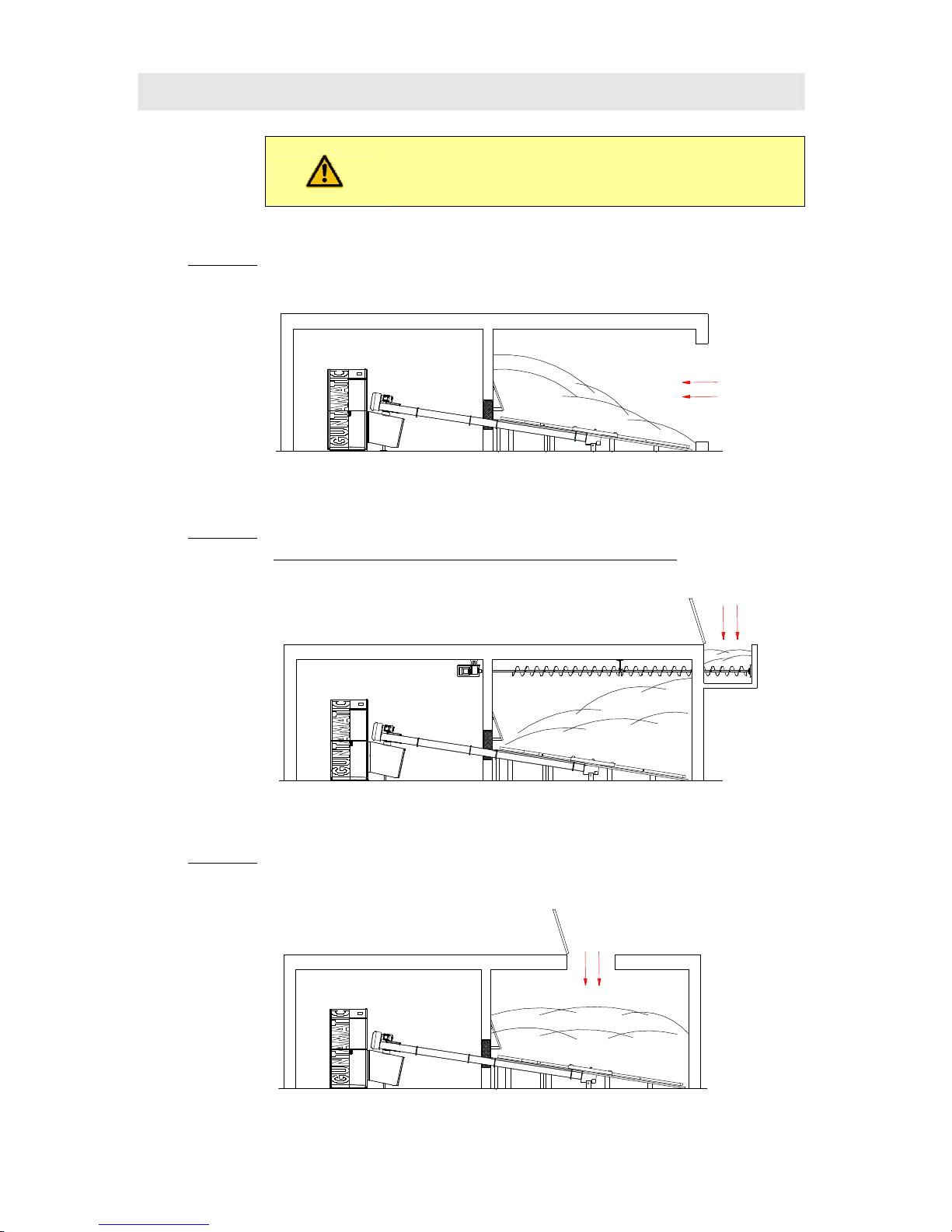
Example 1 The storrage filling occurs through a gate.
The maximal length of feed with the agitator is 7 meter.
Example 2 The storage filling occurs with a ceiling filling spiral through a shaft.
Deliverable ceiling filling spirals are available in following sizes: 3 m, 4 m, 5 m, 6
m or 7 m. The maximal length of holding included the agitator is 7 m.
Example 3 The storage filling occurs through a shift in the storage room ceilling.
The maximal length of holding included the agitator is 7 m.
Page 16
16
For working with Pellets oder Energy corn is a
own filling set needed.
(please have a look at the
price list).
Example 4 The boilers charging occurs with a horizontal installed agitator.
A droft shaft extension is needed. (please have a look on the price list)
The maximal length of holding included the agitator is 7 m.
Example 5 The boilers charging occurs with a horizontal installed agitator.
A in the length shortened downpipe is need.
(Please have a look on the price list).
The maximal length of holding included the agitator is 7 m.
Example 6 The boilers charging occurs with an additional feeder spiral.
A operation set and some spiral´s trags are needed.
(Please have a look on the price
list).
The maximal length of feeder spiral included operation set might have a 7 m
length.
The maximal length of holding included the agitator is 7 m.
Page 17
17
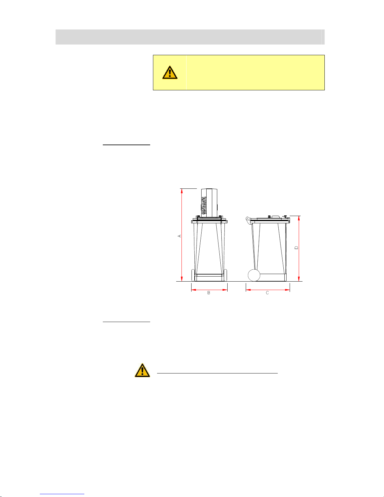
2.8 AUTOMATIC ASH SUCTION SYSTEM
PC-01
The following Introductions are for Device
planning- for installation of ash vacuum suction
system there is another Introduction included.
Optional there is a automatic ash vacuum system. The
accumulated ash will go through the firing build Feedsystem
and flexible metal tube in a big removable ashton. The
deashing is automatically.
Retofit the system It´s possible to retrofit the ash vacuum suction system, if the
minimum difference between the wall and the system ist 60
cm.
A → 153 cm
B → 59 cm
C → 72 cm
D → 107 cm
Construction side: If possible, you have the opportunity to plan the ash ton at a
ground level beside the boiler’s body. Basic requirement for
the construction is a good lifting through the installation site,
The ash ton must have a 25 cm minimum difference to
inflammable materials. You have to be a look that there is no
inflammable ground.
Not permitted construction side for an ash ton:
• in an garage
• in the atmosphere in living rooms;
• in storerooms with inflammable materials or gases.;
Page 18

18
Permited Construction plaeces for the ash ton:
• in the boiler room
• in an secondary
room
Hauling of a suction pipe through fire zones
A → wall penetration with Rockwoolpipesprialclamp;
B → wall penetration with boiled Steel pipe;
C → fire security clamps 54 – 60;
(maximal 1 m difference)
D → flexible suction metal tube
(minimum 10 cm difference)
E → not inflammable mad
Page 19

19
2.9 HEATING CIRCLE RULE
PH-01
The heating circle rule is optional offered.
You can decide between a MKR set or a wall mounted MK 261
set.
●
per construction 3 controlled by atmospheric condition rules
possible
●
per construction could be actived on the MKR Set boiler
●
pro Machine there are 3 remote control möglich;
●
per heatingcircle one analogue room unit possible
Exceptions at five sensors are buffer management
Please note the information in section 5- sensore buffer management of
chapter 7.1 and buffermanagement HP0 !
Set-MKR Following functions could be activated:
Heatingcircle
● Warmwater-Memory
Heatingcirle 0
optional avalible
........
● Pumpenheizkreis
● Zusatz Warmwasser-Speicher
● Externes Heizgerät
Heatingcircle 1
optional avalible
.......
● Pumpenheizkreis
● gemischter Heizkreis
Heatingcircle 2
optional avalible
.......
● Pumpenheizkreis
● gemischter Heizkreis
wall mounted model set-MK261 Following funtions could be active:
Heatingcircle WW
● warmwater- memory
Heatingcircle 0
optional
.................
● pumpingheatingcircle
1)
● third mixed heatingcircle
Heatingcircle 1
optional
.................
● pumpingheatingcircle
● mixed heatingcircle
Heatingcircle 2
optional
.................
● pumpingheatingcircle
● mixed heatingcircle
Trunk link
optional
.........................
● feederpump
(ZUP)
● dumping device pump
(PUP)
● cargo pump
(LAP)
2)
● extension
(ERW)
3)
● third mixed heatingcircle
adition
optional
..............................
● aditional warmwater memory
● external heatingcircle
4)
● third mixed heatingcircle
INFOBOX
1) the third mixed heatingcircle could be actived, if the functions trunk link and addition are not used.
2) through „ERW“ function a heating circle controller with trunk blink can be assigned an other heating circle controller
3) if the function „third mixed heatingcircle“ is activated, the trunk blink functions are not availible.
4) if the „third mixed heatingcircle“ is activated, the additional functions are not availibe.
Page 20

20
NOTES
Sketch:
Page 21

21
3 Construction
01
3.1 Delivery
BS-01
The boiler system is delivered packed in a wooden crate
wrapped in foil. Please check that the delivery is complete
according to the delivery note and in perfect condition.
Deficiencies Please make a note of the deficiencies identified directly on the
delivery note and contact the supplier, heating installer or our
Customer Service.
3.2 Carrying to installation site
BS-01
The system is delivered on a wooden pallet and can be lifted
and carried to the installation site using a pallet truck.
Carrying in dismantled The boiler body can be dismantled into parts for carrying in. If
that is done, a person authorised by GUNTAMATIC must be
consulted.
3.3 Positioning and aligning the boiler
PH-01
Keep to the minimum wall clearances specified by the system
planner and manufacturer. If important details are missing,
please refer to the planning documentation or ask our
Technical Support. Position the system as close as possible to
the flue to avoid having a long flue connecting pipe. The
system must be accessible from the left or right side.
Clearance at back
ideal
70 cm minimum
possible
50 cm
without auto ash extraction system
60 cm
with auto ash extraction system
Clearance on left
ideal
70 cm minimum
possible
40 cm
Clearance on right
ideal
70 cm minimum
possible
40 cm
Clearance at front
ideal
100 cm minimum
possible
80 cm
Floor clearance
ideal
3,5 cm minimum
with screw feet triggered
possible
8 cm
Set the boiler at a slant Unscrew the rear adjustable feet slightly further so that the
boiler is slightly higher at the rear. That will allow the air inside
the boiler to escape easily when the system is filled.
Page 22

22
3.4 Fuel out feed installation
PH-01
Sketch.1
Sketch.2
Sketch.3
1. 1. Set the boiler in accordance with the required minimum
wall-distances in the boiler room place so that sufficient
maintenance space around the boiler, see Sketch.1, exist.
Align the boiler by means of adjustable feet to the rear is
slightly inclined upwards so that existing in the heat
exchanger air can escape easily at the plant filling.Please
note, that the auger feed system has to be constructed right
and just like in sketch 2. , um ca. 90° nach vor oder zurück
geschwenkt werden kann.
2. 2. The storage room should be arranged only slightly lower
than the boiler room. The maximum possible inclinations of
the discharge screw can be seen in the clip values in
sketch 2. With the optional chute extension, see sketch 3,
up to 18 ° tilt are achieved. In disassembled stoker seal the
inlet (A) Sketch 4 insert between stoker unit and Flange
and screw with 4 pieces M08 x 30 hexagon bolts, snap
rings and nuts. The support foot (B) sketch.4. Unscrew the
stoker unit, so that the stoker unit is relieved. The cable
Ignition, TKS, level-tongue, fire engine, Stoker sensor,
actuator G1 and A1 connect drive.
3. Put the propulsive unit (C) Sketch 4 to the Stoker unit and
turn it in direction of the storeroom.
4. Pre assemble the needed Spiraltrogs on the ground.
Construct the in serial delivered trogpiece (F, look at Sketch
4) in the wall breakthrough. Screw the single trogpieces
with M08 x 30 hexagon screw, screw it hard Safety disk
with a locknut and crush. Stick the spirals piece that the
spiral´s lead (G, Sketch 4) is running without a crush or a
break. At least you have to stick the pre assambled Feed
spiral on the drive unit.
5. Construct the agitator (H), look at picture 4 on the Feed
spiral and have a look if the Spirals lead (G) is running
without a break and a pille.
Sketch.4
Page 23

23
Sketch .5
Sketch .6
Sketch .7
Sketch .8
6. The agitator is turning in clockwise direction, look at Sketch
5. The spring arm has to be constructed, that the longest
are in counterpart position. The spring arms have to run 15
to 20 mm above the drawing spiral (look at Sketch 9).
Please don´t fix the screws (J, Sketch 9) on the spring arm.
The feet (K, Sketch 9) on the agitator has to attitude, that
the longest spring and is running 3 to 4 cm over the ground
(look at L, Sketch 9)
7. Fix the unit air tight with screws M10 x 100/ 140 mm (look
at M, Sketch 9) with the Stoker unity. Construct the drive
unit always straight. Look at Sketch 6.
8. Place the agitator in the middle, that the spring arm has a
few cm space to the store room´s wall. The agitator on the
store room´s ground has to screw tightly.
9. Shore the Feed spiral in the store room with the delivered
stanchion below the wall breakthrough- the maximum
distance between the stanchions is 120 cm. The stanchions
have to be on the flanges or on angel brackets. To avoid
the sound transmission you have to put it under an
attenuated mad. You have to attitude the stanchions in
high, that there is enough space fort he spiral. You have to
screw tightly the stanchion. (Look at Sketch 7)
10. The wall breakthrough below (N, Sketch 9). For the closing
of the Feeding spiral you have to close it with the delivered
cover plate and with rock wool. For perforation you have to
cobble the cover plate.
11. You have to screw the bottom plate with M8 x 16 screws
tightly (look at Sketch 8) and you have to insert the bottom
plate below. (look at 0, Sketch 9)
12. The seperation (P) from the inspection opening (look at
picture 7) is sited by manufacture. This measure prohibits
the uncontrolled spread from fuil into the heatingroom. You
have to construct a 40 cm feed spiral which has a wall
distance from 40 cm and got a breadth with 80 cm. You
have to construct also a plank slat in a 20 degree angel.
The construction has to fixed satisfactoired and has to get
fixed enough on the underside.
Sketch .9
Page 24

24
13. The temperature monitoring (TÜB) may be omitted on the
drive unit (Sprinkler 55 ° C) to 50 m³ storage volume due to
the sprinkler device. In stockroom volume greater than 50
cubic meters, the temperature monitoring (segmental) is
also installed on the sprinkler system to the propulsion unit
in the area of the wall and the opening of a warning device
such as ruled at-a bugle. Also from 50 m³ storage volume is
a manually triggered from the boiler room, extinguishing
device (HLE), connected to a pressurized water line and
executed as empty piping DN20, directly to the passage of
space Sweep channel opening out in the fuel storage
installed. The extinguishing equipment must be marked
with a sign "erase fuel storage room".
Sketch .10
14. When wood chips operating a slanted floor is not
mandatory. With grain or pellet operation, however, a
sloping floor should be installed. Sloping floors made of
wood or cement could be constructed on site. With wood
floors slant the boarding of 3 cm thick planed boards or
paste board is finished. The sub-structure of 10 x 10 cm
timber construction, according to Fig.11. customize. The
supports must be on concrete or metal sheets. The
distance between the spring arms to sloping floor must be
15-20 mm. With sloping floor of concrete 2-3 cm away from
the worm trough.
Abb.11
Page 25

25
Sketch .12
Sketch .13
Sketch .14
15. The parellings installation with revisons opening must be
performed like written. In the store room there is a
installade partition (P), look at sketch 7, prohibts at opening
of revisionsquery an uncontrolled spread of stored fuel.
• The Feedspiral has filled out with rockwoll, look at (Q)
picture 12
• The cover plate (R) inside and outside installed (look
at picture 12)
• fix the cover plate (S)- look at picture 12
• Cut the rockwollblock (T) on size of store rooms
opening (look at picture 13)
• The stonewallblock (T), like in picture 13 is delivered
seperatly with a hexagon screw between
revisionsopening (U) and Revisionsbelowside (V)
delivered and installed.
• Put the installed inspection cover (W) and srew it with
wing locknuts.
Q
Q
S
R
T
V
U
W
Page 26

26
3.5 Plumbing connections
PH-01
POWERCHIP 30 - 50 / POWERCORN 50-Special
A → Sensor for temp. relief valve, 1/2"
B → Temperature-relief heat exchanger 3/4“
C → Heating return, 5/4“
D → Heating flow, 5/4”
E → External thermostat, 1/2"
POWERCHIP 75 - 100
A → Sensor for temp. relief valve, 1/2"
B → Temperature-relief heat exchanger 3/4“
C → Heating flow, 2”
D → Heating return, 2“
E → External thermostat, 1/2"
Page 27

27
Temperature-relief heat exchanger The maximum permissible operating temperature of the
boiler is 110°C. In order to prevent the maximum allowable
operating temperature being exceeded, connection of a
temperature-relief valve conforming to Austrian standard
ÖNORM 8131 and DIN 4751 and with a response
temperature of 95°C is required. The supply pressure must
be at least 2 bar but no more than 6 bar.
POWERCHIP 20/30 – 40/50 / POWERCORN 50-Special
A → Cold water supply
B → Sensor for temp. relief valve, 1/2"
C → Temp. relief valve, 95°C
POWERCHIP 75 - 100
A → Cold water supply
B → Sensor for temp. relief valve, 1/2"
C → Temp. relief valve, 95°C
Thermal store Installing a thermal store is not necessary as the boiler is
operated by a modulating control system and the system can
be quickly shut down. However, if the required continuous heat
output in the summer months is below 10 kW for systems up to
50 kW, or 22 kW for systems upwards of 50 kW, combination
with a thermal store is necessary for reasons of efficiency
When you putt he programm „OUT“, the antifreezefunction has
to be secured, if the E heatingsystem is built with an manual
thermostat.
Page 28

28
Return boost The boiler return temperature must be at least 55°C and must
be held at the required level by a bypass pump between the
boiler flow and return pipes. If a thermal store is connected,
the boiler return temperature must similarly be at least 55 °C,
which must be ensured by a return boost (cross-over valve)
set as shown in the plumbing diagram. If this requirement is
not complied with, there is an increased risk of corrosion and
guarantee entitlement will be lost as a result. Connect the
return boost set precisely as specified in our plumbing
diagrams.
The dimensioning of the return boost pump (set) is designed
for the arrangements shown in GUNTAMATIC plumbing
diagrams. If additional components such as heat meters are
incorporated in the system plumbing, or if the overall thermal
store pipe run (flow and return) is more than 30 m, redimensioning of the boiler charging pump (HP0) may be
necessary.
Sludge separator with magnetite Magnetite and the sludge separator in the Heatngwater could
become a problem for energysaver pumps. By installin a
prperly sized and applied sludge sperator with a magnet can
remided cost effenciently.
Either old pipes could be meant
Expansion vessel The boiler operates in a sealed heating system and must be
provided with an expansion vessel for pressure compensation.
To calculate the expansion volume, the volume of the system
when cold must be known. Please select the expansion vessel
on the basis of the manufacturer's specifications. The
expansion volume of the system is calculated as follows:
System volume x Expansion factor x Additional allowance factor
• Expansion factor for wood-fuel boilers = 0.03
• Additional allowance factor = 3.0 for systems under 30 kW
• Additional allowance factor = 2.0 for 30-150 kW systems
Example calculation: 2500 litres x 0.03 x 3 = 225 litres
Pump selection The choice of pump must be made by the installer or building
technology planner on the basis of the friction data, the pipe
cross-sectional area and the required delivery pressure for the
piping system planned.
Plastic piping If plastic piping for underfloor heating or district heating pipes
are connected, they must be protected against excessive
temperatures by using a limiting thermostat for the circulation
pumps.
Danger of overheating Faulty operation, wrong fuil or disturbance could be load to
overheating. To avoid disturbance you have to install
additional fuse protections for maximum process water and
fuses fpr heatingcircle temperatures.
Page 29

29
3.6 Filling and bleeding the system
BS-01
Please note the guidelines on
"Corrosion and boiler protection in
heating and domestic water systems"!
Water quality The water quality of hot water systems with flow temperatures
of max. 100°C is subject to VDI 2035. According to VDI 2035
Part 1, "Avoiding damage to hot water systems", which comply
with EN12828, the first-fill and replenishment water, must be
conditioned (preferably softened) if the following overall
hardness limits [°dH] according to total heat output (kW) are
exceeded:
• < 50kW: if °dH > 16.8
• 50 to 200 kW: if °dH > 11.2
• 200 to 500 kW: if °dH > 8.4
• > 500kW: if °dH > 0.11
Water heater If a water heater is also used in addition to the GUNTAMATIC
boiler, it should be filled according to the installation
instructions for it.
Construction flushing
• Before charging you have to flush the system. When you do
this, it’s the best opportunity to clean magnetit and rust
sludge from the pipe system.
Filling the system
• Match the pressure of the system when cold to the air
charge pressure of the expansion vessel.
• Check the operating pressure on the pressure gauge.
Bleeding the system
• Switch off and bleed circulation pumps.
• Bleed boiler by opening the bleed valve on the boiler and
allowing air to escape until water runs out.
• Bleed radiator heating system (if present) by opening the
bleed valve on every radiator and allowing air to escape
until water runs out.
• Bleed underfloor heating system (if present) by opening
each heating circuit and flushing through thoroughly until
there are no more air bubbles in the heating circuit pipes.
• Important: perform sequence in the correct order!
Start bleeding in the cellar or on the ground floor and finish
in the attic.
• Check the system operating pressure on the pressure
gauge and add more water if necessary.
• Restart circulation pumps.
Only systems that have been properly bled
guarantee effective conveyance of heat.
Page 30

30
3.7 Connecting the flue
PH-01
The boiler is connected to the flue by means of a flue
connecting pipe which must be gas-tight and insulated
between the heating boiler and the chimney.
Flue connecting pipe
→ The following diameters should be used:
• PH 30 - 50 Ø = 150 mm
• PH 75 – 100 / PC 50-S Ø = 180 mm
→ Flue connecting pipes longer than 4 m or with
more than 3 bends:
• PH 30 - 50 Ø = 160 mm
• PC 50-S Ø = 200 mm
• PH 75 – 100 Ø = 220 - 250 mm
The hole in the wall for connecting the flue pipe must be lined
with a built-in double-skinned lining tube or fireproof material.
The flue connecting pipe must rise upwards from the boiler to
the flue at an angle of at least 6° and be connected with gastight joints. An inspection cover must be provided for cleaning
the flue connecting pipe.
A → Flue connecting pipe, min. gradient 6°
B → Flue connecting pipe insulation
C → Flue draught regulator/pressure-surge
compensator in flue
(Preferred fitting arrangement)
D → Alternatively: Flue draught regulator in
flue connecting pipe
(As close as possible to junction with the flue)
• The flue connecting pipe musty be gas-tight
• An energy-saving flue draught regulator with pressure-
surge compensator (Class RE) must be fitted
• Insulate the flue connecting pipe
• Do not brick in the flue connecting pipe (noise
transmission)
• The flue connecting pipe must not extend into the flue
Page 31

31
4 Electrical connections
PH-01
The electrical connections to the boiler system on site may
only be made by an approved electrical installer observing all
the applicable regulations. In addition, it is essential that
electrical system components are protected against damage
from heat radiation.
All boiler system internal wiring is wired up at the factory ready
for use. The work required on site by the electrical installer
consists only of connecting the mains power and wiring up and
connecting the system components such as thermal store,
CAN bus, heating circuit pumps, mixer valve motors, etc.
Opening switch panel
• open the right cover panel (A);
• solve the lock screw (B)
• raise the control cover (C) and hang it below;
• the platine with the connecting plug under accessible
positions
Mains power supply 400 VAC, 50 Hz, 13 A fuse
(surge arrester recommend)
The mains power must be connected by means of the standard
non-reversible power socket on the rear panel of the boiler. It
must possible to isolate the system entirely from the mains
without opening the switch panel cover, e.g. by means of an
automatic circuit-breaker.
Emergency off switch According to prTRVB H 118, it must be possible to switch off
the system using an emergency off switch fitted outside the
boiler room near to the boiler room door. The burner must then
shut down but the heating controller and all safety equipment
must remain functional. Connected to the boiler enabling
switch, terminals 22/23 on the boiler circuit board (see
electrical wiring diagram).
Page 32

32
Cabeling
• Feeder 5 x 1,5 mm²
• Sensor 2 x 1 mm²
• Room stat 2 x 1 mm²
• CAN-Bus 2 x 2 x 0,5 mm²
(twisted pair, shielded)
For low voltage (sensores…) and high voltage, the cable duct
on the boiler, is needed
Surge protection
Where CAN bus cables run between different buildings, the
earthing conductors of the buildings must be connected to each
other for potential equalisation purposes. If the earthing
conductors cannot be interconnected, a 10 mm ring earth must be
laid along with the CAN bus cable in the ground. The earthing
conductors and ring earth must then be connected to one another.
Wiring CAN bus
linear wiring:
(you have to prefer this kind of wiring)
The connection is rewire linear, further cabling the CAN bus,
for example, from the operating unit to the wall unit and the
wall-mounted unit to the remote unity.
wirring radial:
The connection is radial wiring, means the CAN bus, for
example, from the operating unit to the wall unit and the space
station. The total length of the CAN bus connection must not
exceed 100 m in this case.
The terminals +/- and H / L connect each twisted pair.
Boiler cascade
Up to four heating boilers can be operated in a cascade
system (sequential control system) and must be connected inline via a CAN bus. The CAN bus lead must be wired
without connecting the + terminal.
Earthing The entire system is to be joined to the earth circuit conductor
via the connected piping system according to the regulations.
When connecting the earth circuit conductor
pay particular attention to keeping the
connecting runs as short as possible.
Cabel non tensioned to avoid defects or errors all cables strain relieved
Emergency power supply Only use regulated generators.
Page 33

33
4.1 Heating system electrical connections
PH-01
Mains connection
• 400 VAC, 50 Hz, 13 A fuse
Standard specifications
• Boiler control panel
(BCE)
• Boiler circuit board
(230 VAC)
• Router module
(400 VAC)
• Fault signal output
(24VDC 200mA)
• Safety temperature limiter
(STL)
• Boiler sensor
(KVT20 Ω)
• Flue gas temperature sensor
(thermocouple)
• Oxygen sensor
(12V DC)
• Flue draught fan
(230V AC)
• Grate cleaner motor
(230V AC)
• TKS 1
(firebox and ash box door switch, 24VDC)
• TKS 2
(fuel outfeed monitor)
• Stoker drive motor G1
(400V AC)
• Outfeed drive motor A1
(400 VAC)
• Outfeed drive motor A2
(400 VAC – for feeder auger)
• Stoker sensor
(PT1000 Ω)
• Fire safety flap
(24V DC)
• Ignition fan
(230V AC)
• Boiler enabling switch
(emergency off)
• HP0 output
(230 VAC)
• Reflux mixers
(230 VAC)
Optional equipment
• Pump outputs
(230 VAC)
• Mixer valve outputs
(230 VAC)
• sensor entrance
(KVT 20 Ω)
•
anlaloug equipment for furnace
• Digital remote station
Resistances
Temperature
KVT20
Ohm (Ω)
Temperature
PT1000
Ohm (Ω)
-8°C 1537 Ω 0C° 1000 Ω
0°C 1644 Ω 10C° 1039 Ω
10°C 1783 Ω 30C° 1117 Ω
20°C 1928 Ω 40C° 1155 Ω
30°C 2078 Ω 50C° 1194 Ω
40°C 2234 Ω 60C° 1232 Ω
50°C 2395 Ω 70C° 1271 Ω
60°C 2563 Ω 80C° 1309 Ω
70°C 2735 Ω 100C° 1385 Ω
Page 34

34
5 Final checks
BS-01
Final checks
• After completing installation of the system, check again
that all joints and pipes are properly tightened and not
leaking.
• Check that all covers are fitted and secured.
• Check that the fitting of all connections (water, flue,
electrical, ...) has been done correctly.
• Check that all required safety signs and instructions are
attached and hand over all documentation (operating and
installation instructions) for the system.
• Check that all electrical connections have been properly
wired before connecting the system to the power supply.
• Clean the system and clear up the installation site.
• Always leave the boiler room clean.
Initial commissioning Commissioning must only be carried out by GUNTAMATIC or
a qualified specialist. The precondition is that the flue
technician, heating installer and electrician have cleared the
system for operation. The authorised GUNTAMATIC specialist
will carry out the following work during commissioning:
• Check the entire system
• Check the electrical functions
• Adjust the programmer to the system
• Commission the system
• Explain to the user how the system functions and how to
operate and clean it
• Record the details of the customer and the system and
complete the commissioning log
Any deficiencies identified must be recorded in
writing and rectified within the following 4 weeks
in order to maintain guarantee entitlement.
The fully completed commissioning checklist must
be sent to GUNTAMATIC immediately as
otherwise the guarantee will be void.
These installation instructions should not be
destroyed after commissioning but kept
permanently with the system together with the
operating instructions.
Page 35

35
6 Standards / Regulations
BS-01
The heater equates Class 3/ EN 303-5. The original certification report is deposited at the
manufacture, Public Police and Fire safety rules have to be respected.
• ÖNORM / DIN EN 303-5
Heaters for pillar fuel, automatic and manual sanded up to 300 KW. Terms, requirements,
and checkups.
• ÖNORM / DIN EN 12828
heaters for pillar fuel, automatic and manual sanded up to 300 kw, terms, requirements,
checkups and marking
• ÖNORM / DIN EN 12831
Heating for Buildings; method for calculating usual heating board
• ÖNORM M 7137
Requirements on the Pelletstorage at the private customer.
• ÖNORM M 7510
Guideline for the review from central heaters
• ÖNORM H 5195-1
(Austria)
Prevention from damage through nest and Store origin with working temperature.
• VDI 2035
(Germany)
Avoidance from damages in Water heating systems
• SWKI 97-1
(Suisse)
Chalk and Rust Prevention in Waterheaters
• TRVB H 118
(in Austria for automatic sended Machines)
technical heating fire safety rule
• DIN 1988
Technical Rules for drinking water installation
• DIN 4751 Teil 1-4
Safety engineering equipment for water heaters
• Swiss decrees for aircleening
• Swiss decrees with smallfiremachines
• VKF Fire security thermaltechnical construction
(Suisse)
• SIA 384
(Swiss)
Page 36

36
7 Plumbing diagrams
01
7.1 Backup Memory HP0
PH-01
T2
HP0
T3
2 Sensor – Backup Memory
•
Attitude„Part-Charging“
The buffermanagement is charged in the top art. ON and
OFF Switching temperatures could be attitude with
buffermanagement.
•
Attitude „FULL-Charging“
The buffermanagement is charged in the below art. ON
and OFF Switching temperatures could be attitude with
buffermanagement.
HP0
T7
T6
T5
T3
T2
5 Sensor – Backup Memory
PLEASE NOTE:
The buffer sensor additionally required T5, T6 and T7 must
be connected to the boiler board or on a wall unit on the
terminals of the analogue space devices. It can be
programmed for heating circuits therefore this controller no
analogue room device RFF. Alternatively, use digital space
stations RS or an additional wall mounted set-MKR261 for
connecting the analogue room sensor RFF.
•
Attitude „part load border“
The buffer storage tank is loaded up to the adjusted
maximum part load limit at full boiler output. Once this limit
is reached, the boiler output is reduced so much by the
buffer management that this charge state of the buffer can
be kept as long as possible and thus restart the plant are
as far as possible avoided.
Page 37

HP0 mode = Z-pump
37
off 50 kW boiler output
- High-/ lower temperature construction
Attention: In case of very low (less than 30%) decrease of performance like for example a low energy or a passivehouse and
for oversizing, we advice you to install a backup memory.
Diagram no. PH-01
-15
Electrical connections as per operating and installation instructions
1. Powerchip as per price list
2. Flue draught regulator RE as per price list
3. Outside temp. based controller set MKR S30-031
4. DHW cylinder ECO as per price list
5. Mixer valve positioner motor S50-501
6. Room stat as per price list
7. GSM module S15-002
8. Branch control valve plumber
9. Fault indicator lamp plumber
Important: follow wiring diagram!
* Heating circuit 0 can be used with a fixed-setting controller for a low-temperature heating system orHeating
circuit 0 can be room-temperature controlled using an room stat for a radiator heating system.
400VAC
3
2
1
7
9
>55°C
AF
8
HP0
HKP0
5
M
HKP1
HK0
6
RG0
VF1
HK1
RG1
6
SLP0
5
M
HKP2
HK2
VF2
RG2
6
SF0
4
Page 38

HP0 mode = B-pump
38
off 50 kW boiler output
High-/ lower temperature construction with backup memory PSF
Diagram no. PH-02
-15
Electrical connections as per operating and installation instructions
* Heating circuit 0 can be used with a fixed-setting controller for a low-temperature heating system orHeating
circuit 0 can be room-temperature controlled using an room stat for a radiator heating system.
1. Powerchip as per price list
2. Flue draught regulator RE as per price list
3. Outside temp. based controller set MKR S30-031
4. Thermal store PSF as per price list
5. Mixer valve positioner motor S50-501
6. Room stat as per price list
7. GSM module S15-002
8. Return boost set RA50 A H39-021
9. Fault indicator lamp plumber
Important: follow wiring diagram!
10. Option: flange and heat exchanger as per price list
11. 2 Thermal store sensor S70-003
12. Option: Secondary return unit 045-250
2
3
1
400VAC
9
RLM
HP0RL
>55°C
8
7
AF
SF
M
5
M
5
HKP0 H KP1 HKP2
VF1 VF2
10
T2
11
12
230VAC
T3
HK0
RG0
6
RG2RG1
HK1
6
HK2
6
WW
4
KW
POWERCHIP
Page 39

HP0 mode = B-pump
39
off 50 kW boiler output
High-/ lower temperature construction with backup memory PS
Diagram no. PH-03
-15
Electrical connections as per operating and installation instructions
* Heating circuit 0 can be used with a fixed-setting controller for a low-temperature heating system orHeating
circuit 0 can be room-temperature controlled using an room stat for a radiator heating system.
1. Powerchip as per price list
2. Flue draught regulator RE as per price list
3. Outside temp. based controller set MKR S30-031
4. DHW cylinder ECO as per price list
5. Mixer valve positioner motor S50-501
6. Room stat as per price list
7. GSM module S15-002
8. Return boost set RA50 A H39-021
9. Fault indicator lamp plumber
Important: follow wiring diagram!
10. Thermal store PS as per price list
11. 2 Thermal store sensor S70-003
1
3
2
400VAC
>55°C
RL HP0 RLM
8
9
7
AF
M
HKP0
5
HKP1
M
5
HKP2 SLP0
T2
11
HK0
VF1
HK1
RG0
6
RG1
6
VF2
HK2
RG2
6
SF0
4
T3
10
POWERCHIP
Page 40

TAD13 mode = Prog. 4 HP0 mode = B-pump
40
off 50 kW boiler output
High-/ lower temperature construction with backup memory PSF and inventory boiler.
Diagram no. PH-04
-15
Electrical connections as per operating and installation instructions
* Heating circuit 0 can be used with a fixed-setting controller for a low-temperature heating system or.
Heating circuit 0 can be room-temperature controlled using an room stat for a radiator heating system.
1. Powerchip as per price list
2. Flue draught regulator RE as per price list
3. Outside temp. based controller set MKR S30-031
4. Thermal store PSF as per price list
5. Mixer valve positioner motor S50-501
6. Room stat as per price list
7. GSM module S15-002
8. Return boost set RA50 A H39-021
9. Fault indicator lamp plumber
10. Option: Secondary return unit 045-250
11. 2 Thermal store sensor S70-003
12. Flue gas monitor, RGT 80°C H00-801
13. difference scheme TAD 13 S35-101
14. Return boost set RA50 TA H39-022
KFR
PSF
B
e
s
t
a
n
d
s
k
e
s
s
e
l
> 55°C
14
A
RGT 80°C
12
230VAC
S1
TAD13
>55°C
13
3
400VAC
1
2
9
7
AF
RL HP08RLM
230VAC
VF2
M
HKP0
6
RG0
HK0
VF1
M
5
HKP1
5
HKP2
6
RG1
HK1
6
RG2
HK2
10
WW
S2
11
T2
S3
T3
POWERCHIP
TAD13
KW
SF
4
Page 41

HP0 mode = Z-pump
41
off 50 kW boiler output
- High-/ lower temperature construction with with trunk blink.
Attention: In some cases very low power consumption (<30%) such as at a very low energy or passive house, as well as
over-dimensioning, we recommend installing a buffer!
Diagram no. PH-05
-15
Electrical connections as per operating and installation instructions
* Heating circuit 0 can be used with a fixed-setting controller for a low-temperature heating system orHeating
circuit 0 can be room-temperature controlled using an room stat for a radiator heating system.
1. Powerchip as per price list
2. Flue draught regulator RE as per price list
3. Outside temp. based controller set MKR S30-031
4. DHW cylinder ECO as per price list
5. Mixer valve positioner motor S50-501
6. Room stat as per price list
7. GSM module S15-002
8. Return boost set RA50 A H39-021
9. Fault indicator lamp plumber
Important: follow wiring diagram!
10. Flow equaliser plumber
11. District heating pipe plumber
400VAC
1
2
3
>55°C
9
7
AF
10
11
M
HKP0
5
HKP1
RLM
HP0RL
8
HK1HK0
VF1
RG0
6 6
RG1
M
5
HKP2 SLP0
SF0
HK2
VF2
6
RG2
4
Page 42

HP0 mode = B-pump
42
off 50 kW boiler output
High-/ lower temperature construction with backup memory with trunk blink.
Diagram no. PH-06
-15
Electrical connections as per operating and installation instructions
* Heating circuit 0 can be used with a fixed-setting controller for a low-temperature heating system orHeating
circuit 0 can be room-temperature controlled using an room stat for a radiator heating system.
1. Powerchip as per price list
2. Flue draught regulator RE as per price list
3. Outside temp. based controller set MKR S30-031
4. DHW cylinder ECO as per price list
5. Mixer valve positioner motor S50-501
6. Room stat as per price list
7. GSM module S15-002
8. Return boost set RA50 A H39-021
9. Fault indicator lamp plumber
Important: follow wiring diagram!
10. Thermal store PS as per price list
11. District heating pipe plumber
12. 2 Thermal store sensor S70-003
RG0
HKP0
11
3
2
1
400VAC
6
8
RL HP0 RLM
AF
7
9
>55°C
T2
4
SF0
RG2
6
VF2
HK2
SLP0HKP2
5
M
RG1
6
VF1
HK0 HK1
HKP1
5
M
12
POWERCHIP
10
T3
Page 43

HP0 mode = Z-pump
43
off 50 kW boiler output
- High-/ lower temperature construction
Attention: In some cases very low power consumption (<30%) such as at a very low energy or passive house, as well as
over-dimensioning, we recommend you to install a buffer!
Diagram no. PH-07
-15
Electrical connections as per operating and installation instructions
1. Powerchip as per price list
2. Flue draught regulator RE as per price list
3. Outside temp. based controller set MKR S30-031
4. DHW cylinder ECO as per price list
5. Mixer valve positioner motor S50-501
6. Room stat as per price list
7. GSM module S15-002
8. Branch control valve plumber
9. Fault indicator lamp plumber
Important: follow wiring diagram!
* Heating circuit 0 can be used with a fixed-setting controller for a low-temperature heating system orHeating
circuit 0 can be room-temperature controlled using an room stat for a radiator heating system.
1
2
3
>55°C
400VAC
9
HP0
8
M
5
M
5
HKP0 HKP1 HKP2 SLP0
VF1
HK0 HK1
VF2
HK2
SF0
4
7
AF
RG0
6 6
RG1
6
RG2
Page 44

HP0 mode = B-pump
44
off 50 kW boiler output
High-/ lower temperature construction with backup memory PSF
Diagram no. PH-08
-15
Electrical connections as per operating and installation instructions
* Heating circuit 0 can be used with a fixed-setting controller for a low-temperature heating system orHeating
circuit 0 can be room-temperature controlled using an room stat for a radiator heating system.
1. Powerchip as per price list
2. Flue draught regulator RE as per price list
3. Outside temp. based controller set MKR S30-031
4. Thermal store PSF as per price list
5. Mixer valve positioner motor S50-501
6. Room stat as per price list
7. GSM module S15-002
8. Return boost set RA100 A H39-023
9. Fault indicator lamp plumber
Important: follow wiring diagram!
10. Option: flange and heat exchanger as per price list
11. 2 Thermal store sensor S70-003
12. Option: Secondary return unit 045-250
3
1
2
RL
>55°C
8
RLM
HP0
M
7
400VAC
9
AF
5
M
5
M
T2
10
11
HKP0
HK0
HKP1 HKP2
VF1
HK1
VF2
HK2
6
RG0
6
RG1
6
RG2
230VAC
12
T3
SF
WW
4
KW
POWERCHIP
Page 45

HP0 mode = B-pump
45
off 50 kW boiler output
High-/ lower temperature construction with backup memory PS
Diagram no. PH-09
-15
Electrical connections as per operating and installation instructions
* Heating circuit 0 can be used with a fixed-setting controller for a low-temperature heating system orHeating
circuit 0 can be room-temperature controlled using an room stat for a radiator heating system.
1. Powerchip as per price list
2. Flue draught regulator RE as per price list
3. Outside temp. based controller set MKR S30-031
4. DHW cylinder ECO as per price list
5. Mixer valve positioner motor S50-501
6. Room stat as per price list
7. GSM module S15-002
8. Return boost set RA100 A H39-023
9. Fault indicator lamp plumber
Important: follow wiring diagram!
10. Thermal store PS as per price list
11. 2 Thermal store sensor S70-003
2
3
1
400VAC
RL
>55°C
RLM8HP0
M
9
7
AF
HKP0
5
HKP1
M
SLP0
5
M
HKP2
HK0
VF1
HK1
6
RG0 RG1
6
VF2
HK2
SF0
RG2
6
T2
11
4
T3
10
POWERCHIP
Page 46

HP0 mode = Z-pump
46
off 50 kW boiler output
- High-/ lower temperature construction with trunk blink
Attention: In some cases very low power consumption (<30%) such as at a very low energy or passive house, as well as
over-dimensioning, we recommend you to install a buffer!
Diagram no. PH-11
-15
Electrical connections as per operating and installation instructions
* Heating circuit 0 can be used with a fixed-setting controller for a low-temperature heating system orHeating
circuit 0 can be room-temperature controlled using an room stat for a radiator heating system.
1. Powerchip as per price list
2. Flue draught regulator RE as per price list
3. Outside temp. based controller set MKR S30-031
4. DHW cylinder ECO as per price list
5. Mixer valve positioner motor S50-501
6. Room stat as per price list
7. GSM module S15-002
8. Return boost set RA100 A H39-023
9. Fault indicator lamp plumber
Important: follow wiring diagram!
10. Flow equaliser plumber
11. District heating pipe plumber
11
RLM
RL HP0
8
3
2
>55°C
M
1
400VAC
10
M
5
M
5
HKP0 HKP1 HKP2 SLP0
SF0
9
7
AF
HK0 HK1 HK2
VF1 V F2
6
RG0
6
RG1
6
RG2
4
Page 47

HP0 mode = B-pump
47
from 50 kW
High-/ lower temperature construction with backup memory PS and trunk blink
Diagram no. PH-12
-15
Electrical connections as per operating and installation instructions
* Heating circuit 0 can be used with a fixed-setting controller for a low-temperature heating system orHeating
circuit 0 can be room-temperature controlled using an room stat for a radiator heating system.
1. Powerchip as per price list
2. Flue draught regulator RE as per price list
3. Outside temp. based controller set MKR S30-031
4. DHW cylinder ECO as per price list
5. Mixer valve positioner motor S50-501
6. Room stat as per price list
7. GSM module S15-002
8. Return boost set RA100 A H39-023
9. Fault indicator lamp plumber
Important: follow wiring diagram!
10. Thermal store PS as per price list
11. District heating pipe plumber
12. 2 Thermal store sensor S70-003
3
1
2
400VAC
>55°C
RL HP0
8
M
RLM
11
7
9
AF
HKP0
M
5
HKP1
5
M
HKP2 SLP0
HK0
RG0
6
HK1
VF1
6
RG1
VF2
HK2
6
RG2
SF0
T2
12
4
10
T3
POWERCHIP
Page 48

48
DIESES DOKUMENT QURDE VON STEFFEN MÜN ZENBE RG ERSTELL T:
Objekt supply for maximal 3 buildings
trunkblink functions ZUP, LAP oder PUP
Site 1 / Diagram no. PH-13
-15
Electrical connections as per operating and installation instructions
• Line connector 400 VAC / 13 A;
• per System just one Sensor;
(if possible on the boiler)
• per System 3 Wall mounted Set-MK261 possible;
• per System 3 digital Remotestationens possible;
• per Heatingcircle one analouge Remot unit
possible.
Heatingrooms opportunitys
1. Firing Powerchip as Pricelist
2. Flue draught regulator RE with Ex-Clap as Pricelist
3. Regulation wall mounted unit Set-MK261 S30-030
4. W armwater memory ECO as Pricelist
5. Mixer Stellmotor S50-501
6. Remote / Remotestation as Pricelist
7. Backupmemory PS / PSF / 2PS as Pricelist
8. Reverse raising group as Pricelist
9. circulation unity 045-250
10. Backup memory sensor S70-003
11. Flange or recuperator as Pricelist
12. GSM-Modul S15-002
13. Hydraulic switch by client
14. Fernleitung und Fernleitungspumpen by client
15. Pipesystem, by client
16. Alertlamp (look at the circuit diagram) by client
7
HP0 / 2PS
>55°C
1
2
AF
M
RLMRL HP0
8
12
16
10
T2
T3
T5
T6
T7
15
ZUP / LAP
ZUP / LAP
ZUP / LAP
CAN−Bus
HP0 mode = B-pump
15
>55°C
2
1
8
HP0RL RLM
M
ZUP / PUP
ZUP / PUP
ZUP / PUP
AF
12
16
13
CAN−Bus
HP0 mode = Z-pump
Site 2 / Diagram no.
PH-13
-15
Page 49

49
Site 2 / Diagram no. PH-13
-15
Connected size
SLP0
FL
HKP−xHKP−x
M
5
VF−x
HKP−x
M
5
VF−x
14
HK−x HK−x HK−x
LAP
PUP
M M
AF
AF
FL
CAN−Bus
3
3
CAN−Bus
FL
13
666
HKR-x
HKR-x
RG−x
230VAC
RG−x
M
5
RG−x
M
5
HKP−x
HK−x
HKP−x
VF−x
HK−x
6
RG−x
230VAC
6
RG−x
HKP−x
HK−x
VF−x
6
RG−x
14
14
16
16
ZUP
LAP
PUP
CAN−Bus
HKR-x
6
RG−x
230VAC
HKP−x
HK−xHK−x
VF−x
HKP−x
HK−x
HKP−x
VF−x
SLP−x
6
RG−x
6
RG−x
3AF16
5 5
SF0
T2
T3
PS
7
10
4
HKR
11
T2
10
9
WW
KW
7
Netz 230 V
T3
SF
HKR
PSF
4
SF−x
Page 50

HP0 mode = B-pump
50
cascade circuit for 2 Firings
Diagram no. PH-14
-15
Electrical connections as per operating and installation instructions
• Line connector per construction 400 VAC / 13 A;
• connect the system linear with CAN BUS
(lead the wirring without )
• per System 3 mounted system Set-MK261 possible;
• per System 3 digital mounted system possible;
• per Heatingcircle a analouges wall mounted unity possible;
(Exceptions on 5 Feeler buffermanagement)
• at cascades <150 kW could 3“ T-Pipes and the 3“ Bufferconnection dispensed (2“);
1. Firing Powerchip as Pricelist
2. Flue draught regulator RE with Ex-Clap as Pricelist
3. GSM-Modul S15-002
4. recirculationincreasinggroup as Pricelist
5. Buffermemory PS as Pricelist
6. Outdoorsensor S70-001
required on every System without atmosperic Conditions, with additional
above the turned of fOFF Temperature;
7. Buffermemory sensorm S70-003
Advice: alertlamp 5 Sensors per System - minimum 2 per System required
8. Alertlamp (circuit diagram beachten) by client
HP0
6
2"
2" 2"
3"
3"
4
2
11
2
3
AFAF
CAN−Bus
A
RL
>55°C>55°C
RLMRL HP0
M
B
7
55
T5
T3
T3
3"
3"
3"
3"
2"
3"
3"
4
M
RLM
HP0 / 2PS HP0 / 2PS
ZUP
3"
LAP
T7
T6
T2
T2
T5
T6
T7
8
Site 2 / Diagram no.
PH-13
-15
Page 51

HP0 mode = B-pump
51
Cascad circuit for 4 Firing
Site 1 / Diagram no. PH-15
-15
Electrical connections as per operating and installation instructions
• Line connector per construction 400 VAC / 13 A;
• per System 3 mounted system Set-MK261 possible;
• per System 3 digital mounted system possible;
• per Heatingcircle a analouges wall mounted unity possible;
(Exceptions on 5 Feeler buffermanagement)
• the written dimensons fort he backup memory, pipes on T pipes refers to a Cascade with 400
KW and in maximum 2 x 25 m pipe length for buffer forward motion.
1. Firing Powerchip look at Pricelist
2. Flue draught regulator RE with Ex-Clap
3. GSM-Modul S15-002
4. recirculationincreasinggroup look at Pricelist
5. Buffermemory PS look at Pricelist
jeden Puffer mit 2 Stück 3“ Sondermuffen bestellen;
6. Outdoorsensor S70-001
required on every System without atmosperic Conditions, with additional
above the turned of fOFF Temperature;
7. Backup memory sensor S70-003
Advice: alertlamp 5 Sensors per System - minimum 2 per System required
8. alertlamp ( important) by client
HP0
3"
3"
6
2"
2" 2"
4
2
11
2
3
AFAF
CAN−Bus
A
RL
>55°C>55°C
RLMRL HP0
M
B
CAN−Bus
3"3"
3"3"
3"
3"
2"
4
M
RLM
1
2
2"
HP0 RLM
M
4
2"
3"
3"
AF
>55°C
RL
C
AF
CAN−Bus
>55°C
2
1
D
3"
3"
2"
4
M
RLMHP02"RL
8
Site 2 / Diagram no.
PH-15
-15
Page 52

52
Site 2 / Diagram no. PH-15
-15
Electrical connections as per operating and installation instructions
• Order every backup memory with 2 pieces with 3 muffles.
• the written dimensons fort he backup memory, pipes on T pipes refers to a Cascade
with 400 KW and in maximum 2 x 25 m pipe length for buffer forward motion.
Piece of Paper 1 / Diagram no.
PH-15
-15
HP0 / PSHP0 / PS
55
7
T5
T5
T5
T5
T3
T3
T3
T3
3"
4"
3"
3"
HP0 / PS
5
3"
T7
T7
T7
T7
LAP
ZUP
T2
T2
T2
T2
4"
7
T6
T6
T6
T6
3" 3" 3"
3" 3" 3"
Piece of Paper 2 / Diagram no.
PH-13
-15
Page 53

53
NOTES
Sketch:
Page 54

54
* burning from P45A (G50) hackchips just with excellent hackchips
** with additional equipment , not ideal dor your type fuil – check opportunitys with Country and emissionslaw ;
8 Technical data
01
8.1 POWERCHIP 20/30
and
POWERCHIP 40/50
PH-02
Type POWERCHIP 20/30 POWERCHIP 40/50
Fuel
Woodchips P16B and P45A *
Pellets EN Plus A1 oder A2
Grain Fuel **
Miscanthus **
Woodchips P16B oder P45A *
Pellets EN Plus A1 oder A2
Grain Fuel **
Miscanthus **
EN 14961-4
EN 14961-2
ÖNORM M7139
-
Boiler output Woodchips
Boiler output Pellets
Boiler output Grain Fuel
Boiler output Miscanthus
7 – 30
7 – 30
maximum 25
maximum 25
12 – 49
12 – 49
maximum 25
maximum 25
kW
kW
kW
kW
Boiler temperature
Return temperature
60 – 80
> 55
60 – 80
> 55
°C
°C
Required flue draught 2 - 15 2 - 15 Pascal
Water capacity
Operating pressure
128
max. 3
147
max. 3
litres
bar
A - Flue connecting pipe dia
B - Flow
C - Return
D - Temp.-relief heat exchanger
E - Drain
150
5/4
5/4
3/4
1/2
150
5/4
5/4
3/4
1/2
mm
inch
inch
inch
inch
Water system resistance
Temperatur difference 10K
2570
19,6
4257
27,7
kg/h
mbar
Water system resistance
Temperatur difference 20K
1290
11,2
2128
6,2
kg/h
mbar
Ash pan, grate
Ash pan, "heat exchanger”
60
12
60
12
litres
litres
Overall weight
Weight of bottom box
Weight of heat exchanger
Weight of stoker unit
550
340
180
75
585
340
215
75
kg
kg
kg
kg
Power supply 400 VAC / 13A 400 VAC / 13A -
Page 55

55
* burning from P45A (G50) hackchips just with excellent hackchips
** with additional equipment , not ideal dor your type fuil – check opportunitys with Country and emissionslaw ;
8.2 POWERCHIP 75
and
POWERCHIP 100
PH-02
Type POWERCHIP 75 POWERCHIP 100
Fuel
Woodchips P16B and P45A *
Pellets EN Plus A1 oder A2
Grain Fuel **
Miscanthus **
Woodchips P16B oder P45A *
Pellets EN Plus A1 oder A2
Grain Fuel **
Miscanthus **
EN 14961-4
EN 14961-2
ÖNORM M7139
-
Boiler output Woodchips
Boiler output Pellets
Boiler output Grain Fuel
Boiler output Miscanthus
22 – 75
22 – 75
maximum 70
(mit Additiv)
maximum 60
22 – 99/101
22 – 99/101
maximum 70
(mit Additiv)
maximum 60
kW
kW
kW
kW
Boiler temperature
Return temperature
60 – 80
> 55
60 – 80
> 55
°C
°C
Required flue draught 2 - 15 2 - 15 Pascal
Water capacity
Operating pressure
256
max. 3
256
max. 3
litres
bar
A - Flue connecting pipe dia
B - Flow
C - Return
D - Temp.-relief heat exchanger
E – Drain
180
2
2
3/4
1/2
180
2
2
3/4
1/2
mm
inch
inch
inch
inch
Water system resistance
Temperatur difference 10K
6450
4,3
8490
6,2
kg/h
mbar
Water system resistance
Temperatur difference 20K
3250
1,8
4240
2,5
kg/h
mbar
Ash pan, grate
Ash pan, "heat exchanger”
80
12
80
12
litres
litres
Overall weight
Weight of bottom box
Weight of heat exchanger
Weight of stoker unit
865
430
405
75
865
430
405
75
kg
kg
kg
kg
Power supply 400 VAC / 13A 400 VAC / 13A -
Page 56

56
* burning from P45A (G50) hackchips just with excellent hackchips
** with additional equipment , not ideal dor your type fuil – check opportunitys with Country and emissionslaw ;
8.3 POWERCORN 50 Special
PH-02
Type POWERCORN 50 Special
Fuel
Woodchips P16B and P45A *
Pellets EN Plus A1 oder A2
Grain Fuel **
Miscanthus **
EN 14961-4
EN 14961-2
ÖNORM M7139
-
Boiler output Woodchips
Boiler output Pellets
Boiler output Grain Fuel
Boiler output Miscanthus
12 – 49
12 – 49
maximum 40
maximum 40
kW
kW
kW
kW
Boiler temperature
Return temperature
60 – 80
> 55
°C
°C
Required flue draught 2 - 15 Pascal
Water capacity
Operating pressure
147
max. 3
litres
bar
A - Flue connecting pipe dia
B - Flow
C - Return
D - Temp.-relief heat exchanger
E - Drain
180
5/4
5/4
3/4"
1/2"
mm
inch
inch
inch
inch
Water system resistance
Temperatur difference 10K
4240
24,7
kg/h
mbar
Water system resistance
Temperatur difference 20K
2120
6,2
kg/h
mbar
Ash pan, grate
Ash pan, "heat exchanger”
80
12
litres
litres
Overall weight
Weight of bottom box
Weight of heat exchanger
Weight of stoker unit
667
410
227
75
kg
kg
kg
kg
Power supply 400 VAC / 13A -
Page 57

57
8.4 FEED
PH-01
VIEW FROM ABOVE
DELIVERY STATUS
•
bestehend aus Feed unit (AE),Wallpiece (WS) und Agitator (RW );
•
maximum length (GL) of feedspiral = 7 m;
Dumping height:
Hackchips max. 5,0 m
Pellets max. 2,5 m
Energycorn max. 2,5 m
Miscanthus max. 5,0 m
Ø agitator Unit of holdung (AE) Cellar piece (WS) Rührwerk (RW) total length (GL)
1,5 m 73 cm 55 cm 75 cm 203 cm
2,0 m 73 cm 55 cm 100 cm 228 cm
2,5 m 73 cm 55 cm 125 cm 253 cm
3,0 m 73 cm 55 cm 150 cm 278 cm
3,5 m 73 cm 55 cm 175 cm 303 cm
4,0 m 73 cm 55 cm 200 cm 328 cm
4,5 m 73 cm 55 cm 225 cm 353 cm
5,0 m 73 cm 55 cm 250 cm 378 cm
Spiral´s extension
Length
Trogsprial TS 1 22 cm
Trogsprial TS 2 55 cm
Trogsprial TS 3 110 cm
Trogsprial TS 4 220 cm
Trogsprial TS 5 297 cm
Page 58

58
DUMPIRON:
Ø Agitator 64 cm 92 cm 120 cm 147 cm 172 cm 197 cm 225 cm 250 cm
1,5 m 4 off
2,0 m 2 off 2 off
2,5 m 2 off 2 off
3,0 m 2 off 2 off
3,5 m 1 off 1 off 2 off
4,0 m 1 off 1 off 2 off
4,5 m 1 off 1 off 2 off
5,0 m 1 off 1 off 1 off 1 off
HANDOVERSET FOR FEED SPIRAL:
•
existing a Connecting plug (AE) and hardcoverstation (ÜB);
•
Trogsprials (TS1-5) in Table Spirals extensions;
•
maximum total lenghth (GL) = 7 m;
handover Set Length
Antriebseinheit (AE) bis 50 kW 73 cm
Antriebseinheit (AE) ab 100 kW 73 cm
Übergabestation (ÜB) 63 cm
DROP SHAFT EXTENSION:
•
necesarry with Agitator construction in the storeroomm ;
•
deeper storeroom → spiral´s angel possible till 18° ;
Page 59

59
DOWNPIPE up 3 m height:
•
presented over downpipe (OF), below downpipe (UF) and Bride to screw
8.5 Celling filling spiral
PH-01
•
bestehend aus drive motor, Befüllschnecke(n), Lagerplatte und Halterung(en);
•
just for construction for store room´s ceilar ;
•
der Antriebsmotor muss außerhalb des Lagers montiert werden;
Page 60

60
GUNTAMATIC Heiztechnik GmbH
A-4722 Peuerbach / Bruck 7
AUSTRIA
Tel: 0043-(0) 7276 / 2441-0
Fax: 0043 (0) 7276 / 3031
Email: office@guntamatic.com
www.guntamatic.com
Misprints and technichal Changes reserved
 Loading...