

Guntamatic BMK Series, BMK 30, BMK 40, BMK 50, BMK 20 Planning And Installation
Wood logs for 1/2 m split logs englisch
BMK
Planing und Installation
BMK-02
EN-B31-004-V09-1215
Information on this documentation
Please read through this documentation carefully.
It is intended as a reference document and contains important
information on the design, safety, operation, maintenance and
care of your heating system.
We are always looking to improve our products and
documentation. Any ideas and suggestions you may have will be
gratefully received.
GUNTAMATIC Heiztechnik GmbH
Bruck 7
A-4722 PEUERBACH
BS-01
Tel: 0043 (0) 7276 / 2441-0
Fax: 0043 (0) 7276 / 3031
Email: office@guntamatic.com
It is important that you pay particular attention to
the safety issues highlighted in the text by these
symbols.
The entire contents of this document are the property of
GUNTAMATIC and therefore protected by copyright.
Reproduction of any kind, communication to third parties by any
means or use for purposes other than those intended without
the written consent of the owner is prohibited.
2
Subject to printing errors and technical amendments.

CONTENTS
BMK-02
Page
1 Introduction ............................................................................4
1.1 Safety instructions 4
1.2 Gurantee and warranty 4
1.3 Commissioning 4
1.4 Site requirements 4
2 PLANING .................................................................................5
2.1 Fire safety 5
2.2 Minimum fire safety requirements 6
2.3 Heatingroom 7
2.4 Flue requirements 9
2.5 Flue draught regulator and pressure surge compensator 10
2.6 Heatingcirculation rule 11
3 CONSTRUCTION ..................................................................13
3.1 Delivery 13
3.2 Carrying to installation site 13
3.3 Locate and angle the boiler 14
3.4 Plumbing connections 15
3.5 Filling and blending the System 17
3.6 Connecting the Flue 18
4 ELECTRICAL CONNECTIONS .............................................19
4.1 Connections on the Constructions 21
5 FINAL CHECKS.....................................................................22
6 STANDARDS / REGULATIOS ..............................................23
7 CONNECTING DIAGRAMS...................................................25
8 TECHNICHIAL DATA............................................................31
3

1 Introduction
1.1 Safety instructions
BMK-01-PI-01
1.2 Guarantee and warranty
GUNTAMATIC heating systems represent state-of-the-art
technology and meet all applicable safety regulations. Incorrect
installation can endanger life and limb. Heating boilers are
combustion systems and are potentially dangerous if handled
incorrectly. Installation, commissioning and servicing must,
therefore, only be carried out by adequately qualified
technicians observing all regulations and the manufacturer's
instructions.
The manufacturer's guarantee is subject to correct installation
and commissioning of the heating system. Defects and
damage caused by incorrect installation, commissioning or
operation are not covered by the guarantee. To ensure that the
system functions as intended, the manufacturer's instructions
must be followed. Furthermore, only genuine replacement
parts or parts explicitly approved by the manufacturer may be
fitted to the system.
1.3 Commissioning
1.4 Site requirements
Commissioning of the boiler must be carried out by an
authorised GUNTAMATIC specialist or other qualified persons.
They will check whether the system has been installed
according to the plans, adjust the system settings as required
and explain to the system operator how to use the heating
system.
When establishing the site requirements, it is absolutely
essential to take account of the locally applicable planning,
building and implementation regulations and the dimensional
specifications in the fitting guidelines, installation examples and
technical data. Compliance with the locally applicable
regulations and the correct implementation of the measures
required on site are solely the responsibility of the system
owner and are a requirement of the manufacturer's guarantee.
GUNTAMATIC provides no guarantee of any kind for any type
of site work.
4
2 Planning
2.1 Fire safety
01
BS-01
The fire security introductions are obligatory needed on
the construction place
The Compliance from counties ore states fire security
law is obligatory and stands higher then the
GUNTAMATIC fire security instruction
Austria State legislation of the federal states
Technical Directive on Preventative Fire Safety (pr TRVB H118)
Germany Standard boiler regulations (M-FeuVO)
Hessen and Saarland – in these states §16 FeuVO Hessen applies
Switzerland Fire safety regulations
any other exporting countries Any fire safety office
You have to follow you specific country fire safety
rules obligatory. Your country safety rules are higher
then our GUNTAMATIC minimum rules.
If there are no specific fire security rules in your
country, you have to follow the GUNTAMATIC
introductions
(www.vkf.ch)
5

2.2 Minimum fire safety requirements
Boiler room Floor of concrete construction, either bare or tiled. All materials
for floor, walls and ceiling must be fire-resistant to F60 rating.
The boiler room door must be a Class T30 fire door which
opens in the direction of escape and is self-closing. Connecting
doors to the fuel storeroom must also be Class T30 fire doors,
self-closing and lockable. There must be no direct connection
to rooms in which flammable gases or liquids are stored
garage).
(e.g.
01
6

2.3 HEATING ROOM
BMK-02
Minimum Roomheight
Minimum Room tallnes
BMK with Ignition
BMK without Ignition
Minimum Access opening
ideal
H 220 cm
possible at BMK 20-30
possible ati BMK 40-50
ideal
B 200 cm x T 240 cm
left 50 cm / right 50 cm / below 45 cm / above 100 cm
possible
possible
Ideal
possible
possible
B 147 cm x T 209 cm
left 20 cm / right 30 cm / below 45 cm / above 70 cm
B 147 cm x T 199 cm
left 20 cm / right 30 cm / below 35 cm / above 70 cm
T = seeing from the boiler´s rear
B 100 cm x H 160 / 180 cm
Openining lift truck on the transport wood
(Boiler completely constructed / above Transportwood shortened)
B 85 cm x H 150 / 170 cm
Openining lift truck on the transport wood
(Boiler completely constructed / above Transportwood shortened)
B 80 cm x H 80 cm
Openining lift truck on the transport wood
(Boiler completely constructed / above Transportwood shortened)
H 145 cm
H 185 cm
BMK 20-30 / 40-50
Combustion air supply The pressure in the boiler room must not be less than 3 Pa
(0.3 mm H2O). The air vents for boiler rooms must have a
clear, net cross-sectional area of at least 400 cm² and must not
be sealable. The air supply ducting must connect directly to the
outside and if the ducting passes through other rooms, it must
be jacketed to Class F90. On the outside of the building, air
vents must be covered by a protective grille with a mesh size
of > 5 mm. The supply of combustion air should, if possible,
enter at floor level in order to prevent cooling of the boiler
room.
Electrical installation The lighting and the electrical wiring in the boiler room must be
permanently installed.
An Net connector 230 VAC, 50 Hz, 13 A is needed.
Fire extinguisher A hand-held fire extinguisher (6kg gross weight, EN3) must be
mounted outside the boiler room near the boiler-room door.
Protection against freezing The boiler room, pipes carrying water and any district heating
pipes must be protected against freezing.
7
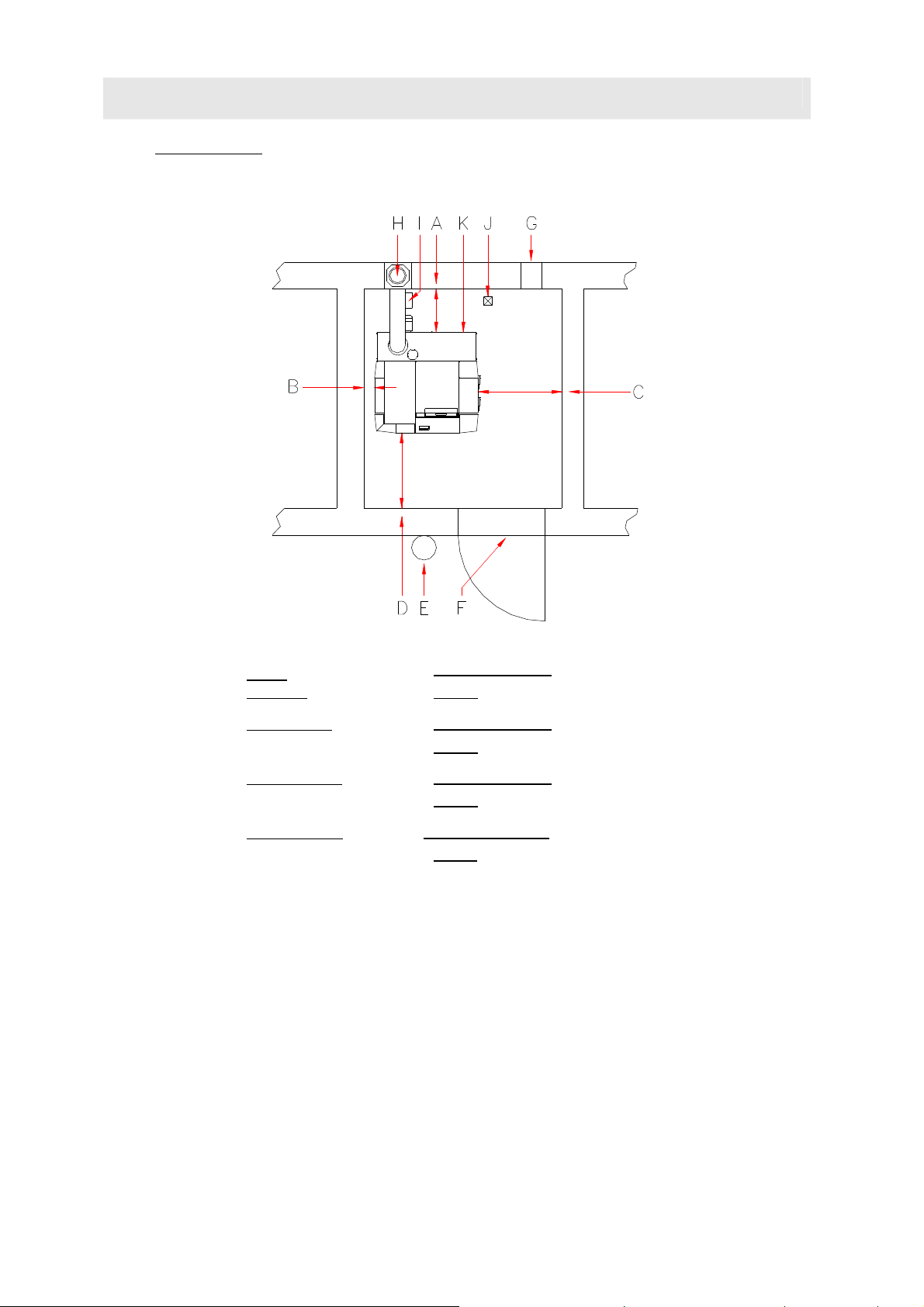
Installation side You have to plan the furnace in the near of the chimney to avoid a long
flue pipe. The heating has to be accesable from the left and the right site.
The Outreach of burningroom and ashdoor must be kept free.
A →
B →
C →
D →
E →
F →
G →
H →
I →
below
Distance
left Distance
right Distance
front Distance
Fire extingiusher
Fire safety door
ideal
possible
ideal
possible
ideal
possible
ideal
possible
6 kg Filler´s weightt EN3
T30 unlockable and self acted closed
Combustion air supply
Flue
wet imun Chamotte-flue advised
45 cm minimum
35 cm
when the BMK is without Ignition
50 cm minimum
20 cm
necaserry Distance for opening of the left door
50 cm minimum
30 cm
necaserry Distance for Serviccing of Servermotor
100 cm minimum
70 cm
Einbauvariante Energiesparzugregler mit Ex-Klappe im Kamin
ca. 50 cm under the flieconnector- please attend the local laws.
Einbauvariante Energiesparzugregler mit Ex-Klappe im Rauchrohr
möglichst nahe am Kaminanschluss – die örtlichen Vorschriften beachten – mögliche Staubbildung
J →
Drain
8
K →
Netconnector 230VAC 13A
2.4 Flue requirements
Flue height The minimum flue height is 5 - 10 m depending on boiler
01
Use heat-insulated fireclay flues that are
insensitive to damp.
GUNTAMATIC accepts no liability where
stainless steel flues are used.
The system must only be connected to the flue if the flue
meets the legal requirements and the technical specifications.
The flue must be matched to the boiler output and
dimensioned in accordance with DIN 4705. In order to be able
to accurately dimension the flue, the calculations must be
based on the flue gas figures. When designing new flues, high
thermal insulation chimneys (DIN 18160 T1 heat transmission
resistance group I) or suitable fireclay flues that are
insusceptible to damp and have general building regulation
approval should be used. It is advisable to involve those
responsible for approving the flue system early on in the
planning phase.
output. The flue must terminate at least 0.5 m above the
highest part of the building. In the case of flat rooves, the flue
must terminate at least 1.5 m above the surface of the roof.
Flue diameter The flue must be matched to the boiler output. The following
details are guide figures and can be used for planning
purposes. However, we recommend that the flue dimensions
are calculated precisely by an expert.
BMK 20/30/40/50
eff. flue height over 6 m D = 180 mm
eff. flue height under 6 m D = 200 mm
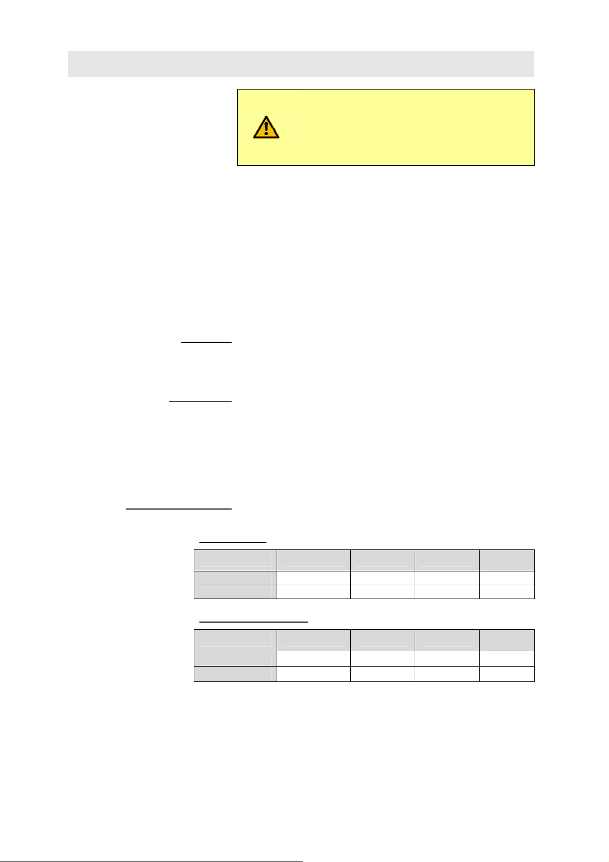
Flue dimensioning data Dimension the flue for rated output!
(Averaged figures with used heat exchanger)
Rated output:
Type Flue gas temp. CO2 Mass flow rate
BMK 20-30
BMK 40-50
200 - 220°C 13 – 14 % 0,020 kg/s 15-20 Pa
200 – 230°C 13 – 14 % 0,034 kg/s 15-20 Pa
Sub-maximum output:
Type Flue gas temp. CO2 Mass flow rate
BMK 20-30
BMK 40-50
170 – 200°C 10 – 12 % 0,011 kg/s 2 Pascal
170 – 200°C 10 – 12 % 0,013 kg/s 2 Pascal
Required
draught
Required
draught
9
2.5 Flue draught regulator and pressure-surge compensator
Fitting an energy-saving flue draught
regulator/pressure-surge compensator
The flue draught should not differ by more than +/- 3 pascals
from the figure specified in the flue dimensioning data. If the
flue draught cannot be reduced to the required figure, either a
larger draught regulator should be fitted or an additional flue
baffle fitted between the flue and the draught regulator.
Purpose
• To ventilate the flue when the system is not in operation
• To compensate for pressure surges
• To regulate and limit the flue draught
Fitting requirement The energy-saving flue draught regulator must be fitted in
accordance with the local regulations, preferably in the flue
approx. 0.5 m below the point where the flue connecting pipe
joins or alternatively in the flue connecting pipe close to its
junction with the flue.
(Class RE) is absolutely imperative.
(if possible 200 mm)
BS-01
Flue draught setting
• Adjusting the flue draught is only of any use at
outside temperatures below +5°C.
•
The system must have been in operation for at least an hour
• Ensure there is sufficient demand for heat for the boiler to
be run at rated output for at least 15 minutes
• Measure the flue draught between the boiler and the flue
draught regulator (distance of measuring point from boiler
ideally 3 x flue diameter from connection between boiler
and flue connecting pipe).
Too much flue draught
May cause the flue gas temperature to increase
and accelerate combustion as a result. Poor
boiler output adjustability, increased dust
discharge and malfunctions can result.
Too little flue draught
Performance problems, incomplete combustion
and malfunctions when operating below rated
output can result.
10
 Loading...