

Page 1

Wood logs for 1/2 m split logs englisch
BMK
Planing und Installation
BMK-02
EN-B31-004-V09-1215
Page 2

Information on this documentation
Please read through this documentation carefully.
It is intended as a reference document and contains important
information on the design, safety, operation, maintenance and
care of your heating system.
We are always looking to improve our products and
documentation. Any ideas and suggestions you may have will be
gratefully received.
GUNTAMATIC Heiztechnik GmbH
Bruck 7
A-4722 PEUERBACH
BS-01
Tel: 0043 (0) 7276 / 2441-0
Fax: 0043 (0) 7276 / 3031
Email: office@guntamatic.com
It is important that you pay particular attention to
the safety issues highlighted in the text by these
symbols.
The entire contents of this document are the property of
GUNTAMATIC and therefore protected by copyright.
Reproduction of any kind, communication to third parties by any
means or use for purposes other than those intended without
the written consent of the owner is prohibited.
2
Subject to printing errors and technical amendments.
Page 3

CONTENTS
BMK-02
Page
1 Introduction ............................................................................4
1.1 Safety instructions 4
1.2 Gurantee and warranty 4
1.3 Commissioning 4
1.4 Site requirements 4
2 PLANING .................................................................................5
2.1 Fire safety 5
2.2 Minimum fire safety requirements 6
2.3 Heatingroom 7
2.4 Flue requirements 9
2.5 Flue draught regulator and pressure surge compensator 10
2.6 Heatingcirculation rule 11
3 CONSTRUCTION ..................................................................13
3.1 Delivery 13
3.2 Carrying to installation site 13
3.3 Locate and angle the boiler 14
3.4 Plumbing connections 15
3.5 Filling and blending the System 17
3.6 Connecting the Flue 18
4 ELECTRICAL CONNECTIONS .............................................19
4.1 Connections on the Constructions 21
5 FINAL CHECKS.....................................................................22
6 STANDARDS / REGULATIOS ..............................................23
7 CONNECTING DIAGRAMS...................................................25
8 TECHNICHIAL DATA............................................................31
3
Page 4

1 Introduction
1.1 Safety instructions
BMK-01-PI-01
1.2 Guarantee and warranty
GUNTAMATIC heating systems represent state-of-the-art
technology and meet all applicable safety regulations. Incorrect
installation can endanger life and limb. Heating boilers are
combustion systems and are potentially dangerous if handled
incorrectly. Installation, commissioning and servicing must,
therefore, only be carried out by adequately qualified
technicians observing all regulations and the manufacturer's
instructions.
The manufacturer's guarantee is subject to correct installation
and commissioning of the heating system. Defects and
damage caused by incorrect installation, commissioning or
operation are not covered by the guarantee. To ensure that the
system functions as intended, the manufacturer's instructions
must be followed. Furthermore, only genuine replacement
parts or parts explicitly approved by the manufacturer may be
fitted to the system.
1.3 Commissioning
1.4 Site requirements
Commissioning of the boiler must be carried out by an
authorised GUNTAMATIC specialist or other qualified persons.
They will check whether the system has been installed
according to the plans, adjust the system settings as required
and explain to the system operator how to use the heating
system.
When establishing the site requirements, it is absolutely
essential to take account of the locally applicable planning,
building and implementation regulations and the dimensional
specifications in the fitting guidelines, installation examples and
technical data. Compliance with the locally applicable
regulations and the correct implementation of the measures
required on site are solely the responsibility of the system
owner and are a requirement of the manufacturer's guarantee.
GUNTAMATIC provides no guarantee of any kind for any type
of site work.
4
Page 5
2 Planning
2.1 Fire safety
01
BS-01
The fire security introductions are obligatory needed on
the construction place
The Compliance from counties ore states fire security
law is obligatory and stands higher then the
GUNTAMATIC fire security instruction
Austria State legislation of the federal states
Technical Directive on Preventative Fire Safety (pr TRVB H118)
Germany Standard boiler regulations (M-FeuVO)
Hessen and Saarland – in these states §16 FeuVO Hessen applies
Switzerland Fire safety regulations
any other exporting countries Any fire safety office
You have to follow you specific country fire safety
rules obligatory. Your country safety rules are higher
then our GUNTAMATIC minimum rules.
If there are no specific fire security rules in your
country, you have to follow the GUNTAMATIC
introductions
(www.vkf.ch)
5
Page 6

2.2 Minimum fire safety requirements
Boiler room Floor of concrete construction, either bare or tiled. All materials
for floor, walls and ceiling must be fire-resistant to F60 rating.
The boiler room door must be a Class T30 fire door which
opens in the direction of escape and is self-closing. Connecting
doors to the fuel storeroom must also be Class T30 fire doors,
self-closing and lockable. There must be no direct connection
to rooms in which flammable gases or liquids are stored
garage).
(e.g.
01
6
Page 7

2.3 HEATING ROOM
BMK-02
Minimum Roomheight
Minimum Room tallnes
BMK with Ignition
BMK without Ignition
Minimum Access opening
ideal
H 220 cm
possible at BMK 20-30
possible ati BMK 40-50
ideal
B 200 cm x T 240 cm
left 50 cm / right 50 cm / below 45 cm / above 100 cm
possible
possible
Ideal
possible
possible
B 147 cm x T 209 cm
left 20 cm / right 30 cm / below 45 cm / above 70 cm
B 147 cm x T 199 cm
left 20 cm / right 30 cm / below 35 cm / above 70 cm
T = seeing from the boiler´s rear
B 100 cm x H 160 / 180 cm
Openining lift truck on the transport wood
(Boiler completely constructed / above Transportwood shortened)
B 85 cm x H 150 / 170 cm
Openining lift truck on the transport wood
(Boiler completely constructed / above Transportwood shortened)
B 80 cm x H 80 cm
Openining lift truck on the transport wood
(Boiler completely constructed / above Transportwood shortened)
H 145 cm
H 185 cm
BMK 20-30 / 40-50
Combustion air supply The pressure in the boiler room must not be less than 3 Pa
(0.3 mm H2O). The air vents for boiler rooms must have a
clear, net cross-sectional area of at least 400 cm² and must not
be sealable. The air supply ducting must connect directly to the
outside and if the ducting passes through other rooms, it must
be jacketed to Class F90. On the outside of the building, air
vents must be covered by a protective grille with a mesh size
of > 5 mm. The supply of combustion air should, if possible,
enter at floor level in order to prevent cooling of the boiler
room.
Electrical installation The lighting and the electrical wiring in the boiler room must be
permanently installed.
An Net connector 230 VAC, 50 Hz, 13 A is needed.
Fire extinguisher A hand-held fire extinguisher (6kg gross weight, EN3) must be
mounted outside the boiler room near the boiler-room door.
Protection against freezing The boiler room, pipes carrying water and any district heating
pipes must be protected against freezing.
7
Page 8
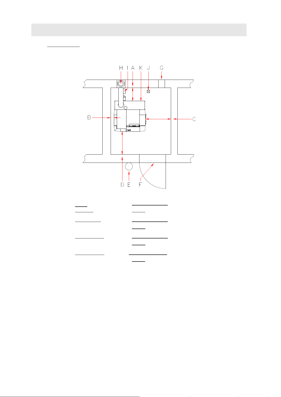
Installation side You have to plan the furnace in the near of the chimney to avoid a long
flue pipe. The heating has to be accesable from the left and the right site.
The Outreach of burningroom and ashdoor must be kept free.
A →
B →
C →
D →
E →
F →
G →
H →
I →
below
Distance
left Distance
right Distance
front Distance
Fire extingiusher
Fire safety door
ideal
possible
ideal
possible
ideal
possible
ideal
possible
6 kg Filler´s weightt EN3
T30 unlockable and self acted closed
Combustion air supply
Flue
wet imun Chamotte-flue advised
45 cm minimum
35 cm
when the BMK is without Ignition
50 cm minimum
20 cm
necaserry Distance for opening of the left door
50 cm minimum
30 cm
necaserry Distance for Serviccing of Servermotor
100 cm minimum
70 cm
Einbauvariante Energiesparzugregler mit Ex-Klappe im Kamin
ca. 50 cm under the flieconnector- please attend the local laws.
Einbauvariante Energiesparzugregler mit Ex-Klappe im Rauchrohr
möglichst nahe am Kaminanschluss – die örtlichen Vorschriften beachten – mögliche Staubbildung
J →
Drain
8
K →
Netconnector 230VAC 13A
Page 9
2.4 Flue requirements
Flue height The minimum flue height is 5 - 10 m depending on boiler
01
Use heat-insulated fireclay flues that are
insensitive to damp.
GUNTAMATIC accepts no liability where
stainless steel flues are used.
The system must only be connected to the flue if the flue
meets the legal requirements and the technical specifications.
The flue must be matched to the boiler output and
dimensioned in accordance with DIN 4705. In order to be able
to accurately dimension the flue, the calculations must be
based on the flue gas figures. When designing new flues, high
thermal insulation chimneys (DIN 18160 T1 heat transmission
resistance group I) or suitable fireclay flues that are
insusceptible to damp and have general building regulation
approval should be used. It is advisable to involve those
responsible for approving the flue system early on in the
planning phase.
output. The flue must terminate at least 0.5 m above the
highest part of the building. In the case of flat rooves, the flue
must terminate at least 1.5 m above the surface of the roof.
Flue diameter The flue must be matched to the boiler output. The following
details are guide figures and can be used for planning
purposes. However, we recommend that the flue dimensions
are calculated precisely by an expert.
BMK 20/30/40/50
eff. flue height over 6 m D = 180 mm
eff. flue height under 6 m D = 200 mm
Flue dimensioning data Dimension the flue for rated output!
(Averaged figures with used heat exchanger)
Rated output:
Type Flue gas temp. CO2 Mass flow rate
BMK 20-30
BMK 40-50
200 - 220°C 13 – 14 % 0,020 kg/s 15-20 Pa
200 – 230°C 13 – 14 % 0,034 kg/s 15-20 Pa
Sub-maximum output:
Type Flue gas temp. CO2 Mass flow rate
BMK 20-30
BMK 40-50
170 – 200°C 10 – 12 % 0,011 kg/s 2 Pascal
170 – 200°C 10 – 12 % 0,013 kg/s 2 Pascal
Required
draught
Required
draught
9
Page 10
2.5 Flue draught regulator and pressure-surge compensator
Fitting an energy-saving flue draught
regulator/pressure-surge compensator
The flue draught should not differ by more than +/- 3 pascals
from the figure specified in the flue dimensioning data. If the
flue draught cannot be reduced to the required figure, either a
larger draught regulator should be fitted or an additional flue
baffle fitted between the flue and the draught regulator.
Purpose
• To ventilate the flue when the system is not in operation
• To compensate for pressure surges
• To regulate and limit the flue draught
Fitting requirement The energy-saving flue draught regulator must be fitted in
accordance with the local regulations, preferably in the flue
approx. 0.5 m below the point where the flue connecting pipe
joins or alternatively in the flue connecting pipe close to its
junction with the flue.
(Class RE) is absolutely imperative.
(if possible 200 mm)
BS-01
Flue draught setting
• Adjusting the flue draught is only of any use at
outside temperatures below +5°C.
•
The system must have been in operation for at least an hour
• Ensure there is sufficient demand for heat for the boiler to
be run at rated output for at least 15 minutes
• Measure the flue draught between the boiler and the flue
draught regulator (distance of measuring point from boiler
ideally 3 x flue diameter from connection between boiler
and flue connecting pipe).
Too much flue draught
May cause the flue gas temperature to increase
and accelerate combustion as a result. Poor
boiler output adjustability, increased dust
discharge and malfunctions can result.
Too little flue draught
Performance problems, incomplete combustion
and malfunctions when operating below rated
output can result.
10
Page 11

2.6 HEATINGCIRCULATION RULE
The heating circle rule is optional offered.
You can decide between a MKR set or a wall mounted MK 261
set.
●
per construction 3 controlled by atmospheric condition rules
possible
●
per construction could be actived just 1 MKR Set boiler
●
pro Machine there are 3 remote control possible;
●
possible
without Heatingcirculation rule
Following functions could be activated:
Heatingcircle WW .......................
Heatingcircle 0............................
Heatingcircle 1............................
BMK-01
per heatingcirculation one analogue room unit
● Warmwater- Memory
● Pumping heatingcirculation
● Pumping heatingcirculation
Set-MKR
wall mounted Set-MK261
Heatingcircle 2............................
● Pumpe heatingcirculation
Following functions could be activated:
Heatingcircle
Heatingcirle 0
Heatingcircle 1
Heatingcircle 2
optional avalible
optional avalible
optional avalible
● Warmwater-Memory
........
● pump heating circulation
● aditional warmwater memory
● external heatingcirculation
.......
● Pump heatingcirculation
● mixed heatingcirculation
.......
● Pump heatingcirculation
● mixed heatingcirculation
Following functions could be activated:
Heatingcirculations WW ..............
Heatingcirculation 0.....................
Heatingcirculation 1
Heatingcirculation 2
wahlweise als..● Pumping heatingcirculation
wahlweise als..● Pump heatingcirculation
● Warmwater-Memory
● Pumping heatingcirculation
● mixed heatingcirculation
● mixed heatingcirculation
11
Page 12

NOTES
Sketch:
12
Page 13

C
3 CONSTRUCTION
01
3.1 Delivery
BMK-01
The boiler system is delivered packed in a wooden crate
wrapped in foil. Please check that the delivery is complete
according to the delivery note and in perfect condition.
Deficiencies Please make a note of the deficiencies identified directly on the
delivery note and contact the supplier, heating installer or our
Customer Service.
3.2 CARRYING TO INSTALLATION SITE
The system is delivered on a wooden pallet and can be lifted
and carried to the installation site using a pallet truck.
Carrying in dismantled The boiler body can be dismantled into parts for carrying in. If
that is done, a person authorised by GUNTAMATIC must be
consulted.
BMK-01
B
D
B
A
B
B
To be able to undo the heat exchanger unions, all of the
insulation must be removed from the boiler. Take care not to
damage the gaskets (B) when lifting off the heat exchanger.
Important: damaged gaskets must always be replaced
without exception.
Pull in carrying straps and position lower section (A) in boiler
room; place gasket strips (B) precisely in position all the way
round; place gasket cord (C) precisely in position on upper
section
Contribute the upper part (D) of the boiler with harrnes or 1
pipes in the heatingroom and put it carefully to the boiler´s
lower part.
ATTENTION: The Sealing strip (B) and the rope seal (C)
might not slipped away!
ATTENTION: The warmwaterexchanger with shirp and srew
it with maximal 30 Nm torque.
13
Page 14

3.3 LOCATE AND ANGLE THE BOILER
Keep to the minimum wall clearances specified by the system
planner and manufacturer. If important details are missing,
please refer to the planning documentation or ask our
Technical Support. Position the system as close as possible to
the flue to avoid having a long flue connecting pipe. The
system must be accessible from the left or right side.
Clearance at rear
Clearance on left
Clearance on right
Clearance at front
Floor clearance
ideal
BMK with Ignition
possible
ideal
possible
ideal
possible
ideal
possible
ideal
possible
45 cm minimum
35 cm
50 cm minimum
20 cm
50 cm minimum
30 cm
100 cm minimum
70 cm
2,5 cm minimum
8 cm
BMK-01
BMK without Ignition
Freespace fort he left cover panel´s door
Freespace for Servermotor Servicing
attend with screwfeed
Set the boiler at a slant Unscrew the rear adjustable feet slightly further so that the
boiler is slightly higher at the rear. That will allow the air inside
the boiler to escape easily when the system is filled.
14
Page 15

3.4 Plumbing connections
A → Flow 5/4“
B → Security warm
heatexchanger 3/4“
C → Emtying 1/2"
D → Backrun 5/4
E → therm. drainvalve 3/4"
residual operation
temperaturer 95°C
F → Cold water supply
G → Security valve 1/2"
Inlet DN15
Outlet DN20
Security warmexchanger A temperature-relief valve to ÖNORM B 8131 and DIN 4751
BMK-03
with an opening temperature of 95°C must be provided on site
and connected to the temperature-relief heat exchanger. The
supply pressure must be at least 2 bar but no more than 6 bar.
The temperature-relief valve must be connected to the cold
water mains supply by a connection that cannot be turned off.
The outlet of the discharge pipe must be routed and installed in
such a way that functional capacity cannot be impaired and no
danger can arise when the temperature-relief valve responds.
The instructions for the temperature-relief valve must be
followed.
Security valve A security valve ½ for heatingcontens after EN 128 28 with
opening pressure has to be installed. The Finish of the
sequence pipe has to be so misplaced, that there is no
impairment of Functionality and there is no Danger. The
instruction for security valves are attented.
buffer memory Installation of an adequately dimensioned thermal store is
absolutely imperative. No guarantee liability is accepted for
systems with a thermal store capacity under 1,000 litres
(= 1,000 litres excluding DHW capacity in the case off combination cylinders).
• Min. thermal store capacity 1,000 litres
• Recommended thermal store capacity Over 1,400 litres
• Ideal thermal store capacity 2,000 – 3,000 litres
Make sure any regulations regarding thermal store size are
observed.
In system with a pure thermal store capacity under 1,400
litres (= 1,400 litres excluding DHW capacity in the case of
combination cylinders) the boiler must be fuelled according to
required output, i.e. it should only be loaded with as much
wood as can be coped with by the system and the thermal
store in the hours that follow.
15
Page 16

When you put the programme „OUT“, the antifreeze function
has to be secured, if the E heating system is built with an
manual thermostat..
Return boost The boiler return temperature must be at least 55°C and must
be held at the required level by a return boost set. Returntemperature regulators in the bypass are not allowed. If this
requirement is not complied with, there is an increased risk of
corrosion and guarantee entitlement will be lost as a result.
If aditional components, such as e.g heat equality counter
integrated into the system hydraulics, ort he total buffer line
length over 30 m (flow and return) can make reinterpreting
boiler/ charge pump (KLP) necaserry.
When using foreign return boost which is not correspond to
these in the flow or control speed of GUNTAMATIC, any
warranty is rejected.
Sludge separator with magnetite Magnetite and the sludge separator in the Heatngwater could
become a problem for energysaver pumps. By installin a
prperly sized and applied sludge sperator with a magnet can
remided cost effenciently.
Either old pipes could be meant
Expansion vessel The boiler operates in a sealed heating system and must be
provided with an expansion vessel for pressure compensation.
To calculate the expansion volume, the volume of the system
when cold must be known. Please select the expansion vessel
on the basis of the manufacturer's specifications. The
expansion volume of the system is calculated as follows:
System volume x Expansion factor x Additional allowance factor
• Expansion factor for wood-fuel boilers = 0.03
• Additional allowance factor = 3.0 for systems under 30 kW
• Additional allowance factor = 2.0 for 30-150 kW systems
Example calculation: 2200 litres x 0,03 x 3 = ~ 200 litres
Pump selection The choice of pump must be made by the installer or building
technology planner on the basis of the friction data, the pipe
cross-sectional area and the required delivery pressure for the
piping system planned.
Plastics pipeline At connection for plastic pipelines for floorheating or district
heating pipeline these temperatures are aditional protected for
a limit thermostat.
Danger of overheating Faulty operation, wrong fuil or disturbance could be lead to
overheating. To avoid disturbance you have to install additional
fuse protections for maximum process water and fuses for
heatingcircle temperatures. You have to install an aditional
16
door for the tap water.
Page 17

3.5 Filling and blending the system
Water quality The water quality of hot water systems with flow temperatures
of max. 100°C is subject to VDI 2035. According to VDI 2035
Part 1, "Avoiding damage to hot water systems", which comply
with EN12828, the first-fill and replenishment water, must be
conditioned (preferably softened) if the following overall
hardness limits [°dH] according to total heat output (kW) are
exceeded:
• < 50kW: with circulating flow heaters, if °dH > 16.8
• 50 to 200 kW: if °dH > 11.2
• 200 to 500 kW: if °dH > 8.4
• > 500kW: if °dH > 0.11
Water heater If a water heater is also used in addition to the GUNTAMATIC
boiler, it should be filled according to the installation
instructions for it.
BS-01
Please attend the guideline for
corrision and boiler´s protection in
heating and service water system!
Flush the Construction
Filling the system
Bleeding the system
• Before filling of the construction flush the whole
pipesystem, to eliminate rust mud and magnetite
• Match the pressure of the system when cold to the air
charge pressure of the expansion vessel
• Check the operating pressure on the pressure gauge
• Switch off and bleed circulation pumps.
• Bleed boiler by opening the bleed valve on the boiler and
allowing air to escape until water runs out.
• Bleed radiator heating system (if present) by opening the
bleed valve on every radiator and allowing air to escape
until water runs out.
• Bleed underfloor heating system (if present) by opening
each heating circuit and flushing through thoroughly until
there are no more air bubbles in the heating circuit pipes.
• Important: perform sequence in the correct order!
Start bleeding in the cellar or on the ground floor and finish
in the attic.
• Check the system operating pressure on the pressure
gauge and add more water if necessary.
• Restart circulation pumps.
Only systems that have been properly
bled guarantee effective conveyance of
heat.
17
Page 18

3.6 Connecting the flue
Flue connecting pipe
BMK-01
The boiler is connected to the flue by means of a flue
connecting pipe which must be gas-tight and insulated
between the heating boiler and the chimney.
→ The following diameters should be used:
BMK 20/30/40/50 Ø = 150 mm
→ Flue connecting pipes longer than 4 m or
with more than 3 bends:
BMK 20/30/40/50 Ø = 180 mm
The hole in the wall for connecting the flue pipe must be lined
with a built-in double-skinned lining tube or fireproof material.
The flue connecting pipe must rise upwards from the boiler to
the flue at an angle of at least 6° and be connected with gastight joints. An inspection cover must be provided for cleaning
the flue connecting pipe.
A → Smokepipe
B → Isolation
(minimum 6° grade)
(z.B. Rockwool)
C → Flue draft regulator with Ex-Clape in the
Flue
(you have to prefer this method)
D → Flue draft regulator with Ex-Klap in the
Smokepipe
(If possible in the near of the flue connector)
• The flue connecting pipe must be gas-tight
• An energy-saving flue draught regulator with pressure-
• Insulate the flue connecting pipe
• Do not brick in the flue connecting pipe
surge compensator
(Class RE)
must be fitted
(noise transmission)
• The flue connecting pipe must not extend into the
flue
18
Page 19

4 ELECTRICAL CONNECTIONS
The electrical connections to the boiler system on site may
only be made by an approved electrical installer observing all
the applicable regulations. In addition, it is essential that
electrical system components are protected against damage
from heat radiation.
All boiler system internal wiring is wired up at the factory ready
for use. The work required on site by the electrical installer
consists only of connecting the mains power and wiring up and
connecting the system components such as thermal store,
CAN bus, heating circuit pumps, mixer valve motors, etc.
BMK-01
open the control panel
• solve the security screw (A);
• cap the control panel (B);
• the circuit board with connecting plugs and securitys is
under in a good accesible position.
Net connector 230 VAC, 50 Hz, 13 A
(over voltage conductor advised)
The mains power must be connected by means of the standard
non-reversible power socket on the rear panel of the boiler. It
must possible to isolate the system entirely from the mains
without opening the switch panel cover, e.g. by means of an
automatic circuit-breaker
Attend on the correct phase Net connection!
Please attend on in that Phase (L) and zero
Signal (N) can´t be changed, becauseo of
the bypassfunction and the securitychain
couldn´t be warranted.
19
Page 20

Cabeling
• Feeder 3 x 1,5 mm²
• Sensor 2 x 1 mm²
• Roomconstruction 2 x 1 mm²
• CAN-Bus 2 x 2 x 0,5 mm²
(paired cable / screened)
Overvoltage protection Where CAN bus cables run between different buildings, the
earthing conductors of the buildings must be connected to
each other for potential equalisation purposes. If the earthing
conductors cannot be interconnected, a 10 mm ring earth must
be laid along with the CAN bus cable in the ground. The
earthing conductors and ring earth must then be connected to
one another.
CAN-Bus cabeling
wirring linear:
(you have to prefer this variation)
The connection is rewire linear, further cabling the CAN bus,
for example, from the operating unit to the wall unit and the
wall-mounted unit to the remote unity.
wirring radial:
The connection is radial wiring, means the CAN bus, for
example, from the operating unit to the wall unit and the space
station. The total length of the CAN bus connection must not
exceed 100 m in this case.
The terminals +/- and H / L connect each twisted pair.
Potencial equalizer splint The whole construction and the conneced pipesystem has to
be connected as prescribed on the potencial equalize splint
system.
Attend on the connection on the potencial
equalizer splint on a short connection.
Cable stain relieved To avoid electrical defects or errors all cables have to be stain
relieved.
Emergency power supply Only use regulated generators.
20
Page 21

4.1 Connections on the Constructions
Net connecting
Standard specifications
• 230 VAC, 50 Hz, 13 A
• Boiler control panel
• Boiler circuit board
• Safety temperature limiter
• Boiler sensor
• Flue gas temperature sensor
• Oxygen sensor
• Flue draught fan
• TKS 1
• Primary/secondary air vent motor
• Ignition fan
• Boiler charging pump output KLP
• Special output HP0
• Backrunmixer
• 1 Memoryloadingpumpexit
• 3 Heatingpumpexit
(right casing door switch, 24V DC)
(BCE)
(230 VAC)
(STB)
(KVT 20 Ω)
(12 VDC)
(230V AC – optional)
(230 VAC)
(230 VAC)
(230 VAC)
(230 VAC – just time controlled)
(thermocouple)
(24 VDC)
(230 VAC)
(230 VAC)
BMK-09
Optional equipment
• Pump outputs
• Mixer valve outputs
• Sensor´s entrance
• Analouge Roomconstruction
• Digital Roomstations
(230 VAC)
(KVT 20 Ω)
(230 VAC)
Resistances
Temperature KVT20
-20°C 1383 Ω
-16°C 1434 Ω
-8°C 1537 Ω
-4°C 1590 Ω
0°C 1644 Ω
10°C 1783 Ω
20°C 1928 Ω
30°C 2078 Ω
40°C 2234 Ω
50°C 2395 Ω
60°C 2563 Ω
70°C 2735 Ω
80°C 2914 Ω
21
Page 22

5 Final checks
Final checks
Initial commissioning Commissioning must only be carried out by GUNTAMATIC or
BS-05-PI-01
• After completing installation of the system, check again
that all joints and pipes are properly tightened and not
leaking.
• Check that all covers are fitted and secured.
• Check that the fitting of all connections (water, flue,
electrical) has been done correctly.
• Check that all required safety signs and instructions are
attached and hand over all documentation (operating and
installation instructions) for the system.
• Check that all electrical connections have been properly
wired before connecting the system to the power supply.
• Clean the system and clear up the installation site.
• Always leave the boiler room clean.
a qualified specialist. The precondition is that the flue
technician, heating installer and electrician have cleared the
system for operation. The authorised GUNTAMATIC specialist
will carry out the following work during commissioning:
• Check the entire system
• Check the electrical functions
• Adjust the programmer to the system
• Commission the system
• Explain to the user how the system functions and how to
operate and clean it
• Record the details of the customer and the system and
complete the commissioning log
Any deficiencies identified must be recorded in
writing and rectified within the following 4 weeks
in order to maintain guarantee entitlement.
The fully completed commissioning checklist
must be sent to GUNTAMATIC immediately as
otherwise the guarantee will be void.
These installation instructions should not be
destroyed after commissioning but kept
permanently with the system together with the
operating instructions.
22
Page 23

6 Standards / Regulations
BS-01
The heater equates Class 3/ EN 303-5. The original certification report is deposited at the
manufacture, Public Police and Fire safety rules have to be respected.
• ÖNORM / DIN EN 303-5
Heaters for pillar fuel, automatic and manual sanded up to 300 KW. Terms, requirements,
and checkups.
• ÖNORM / DIN EN 12828
heaters for pillar fuel, automatic and manual sanded up to 300 kw, terms, requirements,
checkups and marking
• ÖNORM / DIN EN 12831
Heating for Buildings; method for calculating usual heating board
• ÖNORM M 7137
Requirements on the Pelletstorage at the private customer.
• ÖNORM M 7510
Guideline for the review from central heaters
• ÖNORM H 5195-1
(Austria)
Prevention from damage through nest and Store origin with working temperature.
• VDI 2035
(Germany)
Avoidance from damages in Water heating systems
• SWKI 97-1
(Suisse)
Chalk and Rust Prevention in Waterheaters
• TRVB H 118
(in Austria for automatic sended Machines)
technical heating fire safety rule
• DIN 1988
Technical Rules for drinking water installation
• DIN 4751 Teil 1-4
Safety engineering equipment for water heaters
• Swiss decrees for aircleening
• Swiss decrees with smallfiremachines
• VKF Fire security thermaltechnical construction
• SIA 384
(Swiss)
(Suisse)
23
Page 24

NOTES
Sketch:
24
Page 25

Heatingcirculations time controlled – without atmospheric controlled rule
Warmwatermemory ECO – Buffermemory PS
Diagram no : BMK-01
-14
Electrical connections as per operating and installation instructions
HK0
HK1
HK2
1. Firing BMK as pricelist
2. flue draft regulator with Ex-Clap RE20 H38-160
3. Return boost group RA50 A H39-021
4. Warmwatermemoryr ECO as price list
5. buffermemory PS as price list
BMK
5
T3
230VAC
HP0 HP1
>55°C
1
2
M
RLMKLPRL
3
HP2 SLP0
SF0
4
T5
T2
25
Page 26

Heatingcirculation time controlled – with atmospheric condition loaded rule
Warmwatermemory ECO – 2 buffermemory PS
Diagramme Nr.: BMK-02
-14
Electrical connections as per operating and installation instructions
* The heating circulation could be operated roomtemperature controlled...
RG2RG1RG0
6
AF
HK0
9
HK1
VF1 VF2
HK2
1. Firing as Price list
2. Flue draft regulator with Ex-Klappe RE20 H38-160
3. Rule Set-MKR S30-031
4. Return boost group RA50 A H39-021
5. Mixer Servermotor S50-501
6. Roomconstruction / Roomstation as Price list
7. Warmwasserspeicher ECO as Price list
8. buffermemory PS as Price list
9. GSM-Module S15-002
BMK
8
T3
8
T5
230VAC
HKP0 HKP1
>55°C
1
2
3
M
RL
RLMKLP
4
M
HKP2 SLP0
5
M
7
T2
26
Page 27

Heatingcirculation time contolled – with atmospheric controlled rules
1 Pufferspeicher PSF incl. Freshwaterstation – 1 buffer memory PS - Solarconstruction
Diagramme No.: BMK-03
-14
Electrical connections as per operating and installation instructions
* The heating circulation could be operated roomtemperature controlled..
RG0 RG1 RG2
AF
HK0
11
HK1 HK2
VF1
6
VF2
WW
230VAC
KW
1. Firing BMK as pricelist
2. Flue draught regulator mit Ex-Klappe RE20 H38-160
3. Rule Set-MKR S30-031
4. Return boost group RA50 A H39-021
5. Mixer servemotor S50-501
6. Roomconstruction / Roomstation as pricelist
7. buffermemory PSF inkl. FWS as pricelist
8. Option Cirkulationsunit 045-250
9. buffermemory PS as pricelist
10. Option Flange and warmheatexchanger as pricelist
11. GSM-Module S15-002
BMK
7
T3
9
T5
230VAC
HKP0 HKP1
>55°C
1
2
3
M
RLMRL KLP
4
HKP2
5
M M
8
10
T2
27
Page 28

Combination with existing oil/ gas boiler
ATTENTION: non qualified for gas thermics!
- controlled by atmospheric conditions heatingcirculationrule in the existing boiler
Scheme No.: BMK-05
-15
Electrical connections as per operating and installation instructions
INFO: 1) The oil and gas boiler will be through the function ZP always kept on temperature – please attend on good isolation of the
FUNCTION:
boiler.
2) The radiation loose on the oil/ gas boiler has to be respected.
3) A smokegasthermostat in the flue is just necaserry, when both boiler are conducted in the same flue.
About the difference control T3 - T5 of BMK system pump is driven (ZP), thus supplying the oil / gas boiler with heat.
The oil / gas boiler starts only when enough energy from the buffer memory in the oil / gas boiler is supplied.
AF
5
T3
HK0
1. Firing BMK as pricelist
2. Flue draft regulator with Ex-Clap RE20 H38-160
3. Oil / Gasboiler by client
4. Return boost group RA50 A H39-021
5. buffermemory PS as pricelist
6. smokegasthermostat H00-801
HK2HK1
e
s
T5
Bestandskessel
a
h
p
r
e
n
n
e
r
B
3
M M
RGT > 88°C6
1
2
230VAC
>55°C
RL KLP
RLM
M
4
T2
HP0
Attiude HP0 = ZP 28
Page 29

Combination with blocking of an Oil/ Gasconstruction
ATTENTION 1) qualificated for oil or gasboiler and gas thermics
2) for gasthermics there is an hydraulic seperation advicable
by armospheric conditions heatingcirculation with BMK
Diagramme No.: BMK-16-8
Electrical connections as per operating and installation instructions
-14
INFO: 1) By gasthermic in the Parameter „HP0“ the parameter has to be attituded to „burn cont.“ to 2- 3 minutes.
2) all securityconstructions on the oil/ gasconstruction have to run correctly.
3) Switch USV to oil/ gasconstruction= Exit „HP1“= Order „OFF“
FUNCTION: The oil / gas appliance is required by the "lockup" of BMK, if the temperature at the "Buffer sensor UP" (T3) is less than the
highest required target temperature of a heating or hot water circuit.
Following conditions must be leaded out::
1) The parameter „HP0“ in the costumer menu is attituded to „AUTO“ or „DURATION“.
2) The temperature on „buffer sensor ABOVE“ (T3) is smaller then the highes wanted target temperature.
3) The temperature on the „buffersensor BELOW “ (T3) iss maller then the in the parameter „TP0 blocked temperature“.
4) The exhaust gas temperature of BMK is smaller, then the in the parameter „RGT Burner“ attituded temperature.
5) For boiler with automatically „Ignitionblocking“ the Ignition has to be runned over.
AF
11
5 5
RG0 RG1
T5T3
HK0
1. Firing BMK as Pricelist
2. Flue draft regulator with Ex-Clap RE20 H38-160
3. Rule Set-MKR S30-031
4. return boost grouo RA50 A H39-021
5. buffermemory PS as Pricelist
6. USV 5/4“ by client
use just zone valves with off turned and tight closed mixer
7. aditional boiler sensor for Oil-/ Gasconstr. S70-004
8. Mixer Servermotor S50-501
9. Roomconstruction / Roomstation as Pricelist
10. Warmwatermemory ECO as Pricelist
11. GSM-Module S15-002
RG2
9
HK1 HK2
VF1
VF2
230VAC
HKP0 HKP1
6
HP2
B
USV
ABM
HP1
A
HP0 −
>55°C
1
2
3
M
RL
KLP
RLM
4
T2
230VAC−2A
T4
t
ä
7
r
e
g
s
a
G
/
−
l
Ö
HKP2
8
M
SLP0
M
10
29
Page 30

NOTES
Sketch:
30
Page 31

8 TECHNICHAL DATA
BMK-02
Type BMK 20 BMK 30 BMK 40 BMK 50 Unity
Fuel Split log
natural finish
rating 20 30 40,3 (39,4*) 50 (42,5*) kW
boiler temperature
Return boost temperaturer
Flue draft
Water content
Opration pressure
A – Smoke pipe (Diameter)
B - Backrun
C – Vorlauf
D – Securitywarmexchanger
Waterside resistance 10K
Wasserseitiger Widerstand 20K
65 – 85
> 55
2 - 20 2 - 20 2 - 20 2 - 20 Pascal
125
max. 3
150
5/4
5/4
3/4
1710 l/h
3,8
860 l/h
1,1
Split log
natural finish
65 – 85
> 55
125
max. 3
150
5/4
5/4
3/4
2570 l/h
8,1
1290 l/h
2,5
Split log
natural finish
65 – 85
> 55
175
max. 3
150
5/4
5/4
3/4
3430 l/h
15,4
1710 l/h
3,9
Split log
natural finish
65 – 85
> 55
175
max. 3
150
5/4
5/4
3/4
4290 l/h
24,1
2140 l/h
6,0
-
°C
°C
Litre
bar
mm
Zoll
Zoll
Zoll
l/h - kg/h
mbar
kg/h
mbar
Volume filling roo0m 166 166 215 215 Liter
boiler´s weigh ca.
weight warmexchanger
weight lower part
Power supply
630
240
350
230VAC / 13A 230VAC / 13A 230VAC / 13A 230VAC / 13A
630
240
350
730
320
350
730
320
35
* Powerrating for Germany
kg
kg
kg
31
Page 32

GUNTAMATIC Heiztechnik GmbH
A-4722 Peuerbach / Bruck 7
Tel: 0043-(0) 7276 / 2441-0
Fax: 0043 (0) 7276 / 3031
Email: office@guntamatic.com
www.guntamatic.com
Misprints and technichal Changes reserved
32
 Loading...