

Page 1

Pellet boiler englisch
BIOSTAR
FLEX/BOX/W
Operating Instructions/System Log Book
BS-A-00-00-00-01-BAEN
EN-B30-003-V16-0411-V3.0
Page 2
BIOSTAR Operating instructions
2
Information on this documentation
BS-B-00-00-00-01-BAEN
Please read through this documentation carefully.
It is intended as a reference document and contains important
information on the design, safety, operation, maintenance and
care of your heating system.
We are always looking to improve our products and
documentation. Any ideas and suggestions you may have will
be gratefully received.
GUNTAMATIC Heiztechnik GmbH
a Georg Fischer Group Company
Bruck 7
A-4722 PEUERBACH
Tel: 0043 (0) 7276 / 2441-0
Fax: 0043 (0) 7276 / 3031
E-mail: info@guntamatic.com
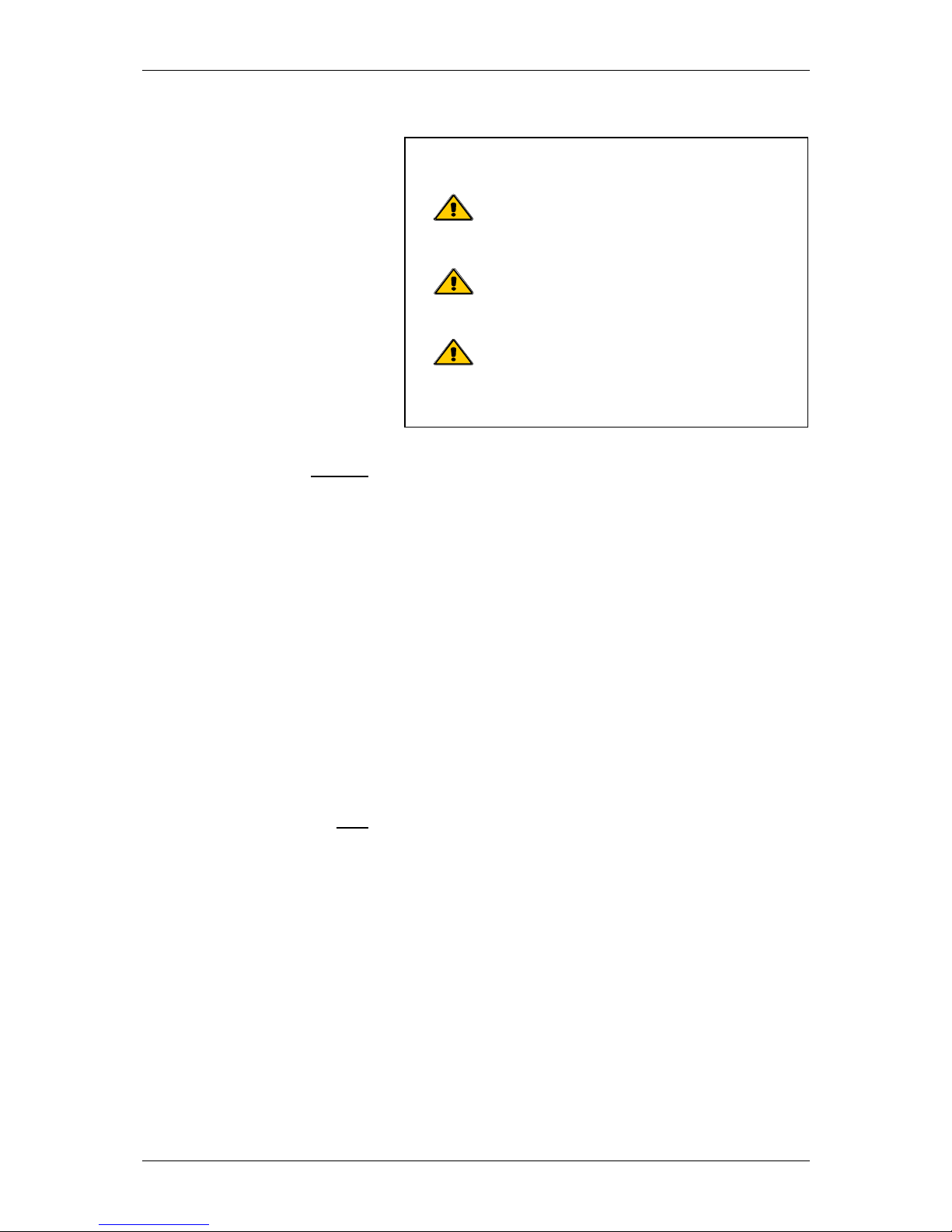
It is important that you pay particular
attention to the safety issues highlighted in
the text by these symbols.
The entire contents of this document are the property of
GUNTAMATIC and therefore protected by copyright.
Reproduction of any kind, communication to third parties by
any means or use for purposes other than those intended
without the written consent of the owner is prohibited.
Subject to printing errors and technical amendments.
Page 3

BIOSTAR Operating instructions
3
Contents
BS-C-00-00-00-01-BAEN
Page
1 Introduction..........................................................5
1.1 Brief description 5
1.2 Type approval 5
1.3 Further information 5
2 Important notes....................................................6
2.1 Intended use 6
2.2 Operating the heating system 6
2.3 Guarantee and liability 6
2.4 Safety instructions 7
3 System components..........................................11
3.1 Cutaway diagram of Biostar FLEX 11
3.2 Cutaway diagram of Biostar W 12
4 Safety systems...................................................13
5 Description of control panel .............................14
6 Overview of menu and levels............................15
6.1 Information level 16
6.2 House level 17
6.3 User level 17
6.3.1 Heating Circuit
menu
18
6.3.2 Hot Water
menu
18
6.3.3 Thermal store
menu
19
6.3.4 User
menu
19
6.3.5 Detail View
menu
19
6.3.6 Date/Time
menu
19
6.4 Service level 20
6.4.1
Service menu
Reset Data 20
6.4.2
Service menu
Fault screen 20
6.4.3
Service menu
Commissioning 21
6.4.4
Service menu
Heating Circuit/
Screed Drying Prog. Parameters
22
6.4.5
Service menu
Hot Water Parameters 23
6.4.6
Service menu
HP0 Parameters 23
6.4.7
Service menu
System Settings 24
7 User settings ......................................................25
7.1 Activating a heating programme 25
7.2 Deactivating a heating programme 26
7.3 Setting a timer programme 27
7.3.1 Programming en bloc 27
7.4 Changing the heating characteristic 28
7.5 Changing the hot water temperature setting 29
7.6 Analogue room stat 30
7.7 Digital room controller 30
Page 4

BIOSTAR Operating instructions
4
Contents
Page
8 Operating the heating system...........................31
8.1 Starting up/Shutting down the system 31
8.2 Heating system checks 31
8.3 Fuel quality 32
8.4 Fuels 33
8.4.1 Pellets 33
8.5 Fuel storage 33
8.6 Filling/refilling the fuel store 34
8.7 Emptying the ash 35
9 Cleaning/care .....................................................36
9.1 Cleaning the fuel store 36
9.2 Interim cleaning 37
9.3 Complete cleaning 38
10 Rectifying faults.................................................39
11 Information messages/Fault codes ..................40
12 Replacing fuses .................................................41
13 Log book.............................................................42
Page 5

BIOSTAR Operating instructions
5
1 Introduction
BS-01-00-00-00-01-BAEN
You have made an excellent choice with the purchase of your
GUNTAMATIC boiler.
It is a product of many year's experience in boiler-making and
it is our sincere wish that your heating system provides you
with many years of satisfaction.
These instructions are intended as a guide to operation and
maintenance. Even the best boiler cannot operate effectively
without proper care and maintenance, so please read through
these instructions carefully and have your appliance
commissioned by an engineer authorised by GUNTAMATIC.
Most importantly, you should follow the safety instructions in
Section 2.
1.1 Brief description
BS-01-01-00-00-01-BAEN
The BIOSTAR is a modern biomass boiler available with
power outputs of 12, 15 or 23 kW. The fuel is fed either from a
boiler-mounted hopper by an auger-type conveyer or from a
separate fabric hopper or storeroom by an auger conveyor
and vacuum system.
1.2 Type approval
BS-01-02-00-00-01-BAEN
The boiler is designed as a Class 3 appliance as defined by
the draft standard ÖNORM EN 303-5 (CEN/TC7/WG 1 – Doc.
N 36-D) of 15/12/1996 and the agreement of the [Austrian]
Federal States according to Art. 15a BVG, in accordance with
the Austrian fire safety regulations, safety systems, CE and on
safety measures for small combustion heating systems and
the combustion heating system approval regulations (LGBl.
33/1992) of the Federal State of Steiermark. The original type
approval certificates are available for inspection at the
manufacturer's offices.
1.3 Further information
BS-01-03-00-00-01-BAEN
The documentation consists of the following documents:
• Planning Document
• Installation instructions
• Operating instructions
If you have any questions, please consult our Customer Support.
Page 6

BIOSTAR Operating instructions
6
2 Important notes
BS-02-00-00-00-01-BAEN
Your boiler has been designed and produced in accordance
with the latest technical advances and all applicable safety
regulations. Nevertheless incorrect operation, the use of
unapproved fuels or the failure to carry out necessary
maintenance and repairs can result in personal injury or
damage to property. You will avoid dangerous situations by
only using the boiler for the purpose for which it was designed
and by operating, cleaning and maintaining it correctly. Only
start up the heating system when it is in perfectly safe working
order.
2.1 Intended use
BS-02-01-00-00-01-BAEN
The boiler is designed for heating central heating water and
for use as a central heating boiler.
2.2 Operating the heating system
BS-02-02-00-00-01-BAEN
The heating system may only be operated and cleaned by
demonstrably trained persons (as per check-list). Children,
unauthorised persons or persons with a mental impairment
may only enter the boiler room under the supervision of an
authorised person. When unsupervised, the boiler room/fuel
store must be locked and the key kept in a place where it is
inaccessible to such persons.
2.3 Guarantee and liability
BS-02-03-00-00-01-BAEN
Guarantee and liability claims for personal injury and/or
property damage are inadmissible if they are attributable to
one or more of the following causes:
• use of the boiler for purposes other than that intended
• failure to follow the instructions, guidance and safety
precautions given in the documentation
• incorrect commissioning, operation, maintenance or
repair of the boiler
• operation of the boiler when safety systems are
inoperative
• unauthorised modifications
Caution:
Do not use the boiler to burn rubbish!
Burning rubbish will cause extensive
corrosion and consequently to a
substantial reduction in the service life of
the boiler.
Caution: even if the opposite is requested, servicing
and repair work may only be carried out by
authorised specialists.
Page 7
BIOSTAR Operating instructions
7
2.4 Safety instructions
BS-02-04-00-00-01-BAEN
To prevent accidents, small children should not be allowed
into the boiler room or the fuel storeroom. Please follow the
safety instructions below. By doing so, you will protect yourself
and prevent damage to your heating system.
Power switch
BS-02-04-00-01-01-BAEN
Mains plug
BS-02-04-00-02-01-BAEN
Repair work
BS-02-04-00-03-01-BAEN
In an emergency: In the event of electric shock, disconnect
the power supply immediately.
Administer first aid. Call the duty doctor.
Fault rectification
BS-02-04-00-04-01-BAEN
Unauthorised modifications
BS-02-04-00-05-01-BAEN
Note: The power switch must remain switched on at
all times and may only be switched off when
the system is not in operation.
Danger: Risk of fatal injury from electric shock.
The mains power supply is brought to the
boiler via the plug marked Mains. That plug
and other components of the system remain
live even when the Power switch on the
control panel is switched off.
Danger: Repair work may only be carried out
by authorised technicians.
Touching live electrical components can
cause fatal injury.
Even when the Power switch is "OFF" some
components of the system are still live.
Therefore, when carrying out repair work it is
imperative that the power supply to the
heating system is disconnected by means of
the "mains plug" or a circuit breaker.
Note: If faults occur, the causes must first be
eliminated on the basis of the information
message on the display (F0...) before
resuming operation by means of the "Quit"
button.
Note: do not make any unplanned changes to the
settings or any modifications to the heating
system.
Loss of guarantee entitlement
Page 8
BIOSTAR Operating instructions
8
Servicing work
BS-02-04-00-06-01-BAEN
Emptying ash
BS-02-04-00-07-01-BAEN
Boiler cleaning
BS-02-04-00-08-01-BAEN
Flue gas fan
BS-02-04-00-09-01-BAEN
Gaskets
BS-02-04-00-10-01-BAEN
In an emergency: Take the person affected into the open
air immediately. Call the duty doctor.
Air supply
BS-02-04-00-11-01-BAEN
Note: If there is more than one boiler in the same room, a
greater supply of fresh air must be provided.
Note: Service the boiler regularly or make use of
our Customer Service.
Danger: Glowing embers can cause fires.
Only remove the ash from the boiler or store it
in non-combustible containers.
Caution: Touching hot components can
cause skin burns.
The boiler must only be cleaned when it is
cold (flue gas temperature < 50°C)
Danger: Risk of injury from rotating parts.
The fan must only be removed when it is
disconnected from the power supply
(unplugged).
Danger: Risk of gas poisoning.
It is possible that flue gas could escape if
gaskets are damaged.
Have defective gaskets replaced by an
authorised technician.
Danger: Risk of suffocation
Inadequate air supply can be fatal.
Make sure there is an adequate supply of air.
Page 9
BIOSTAR Operating instructions
9
Flue draught regulator
BS-02-04-00-12-01-BAEN
Safety clearances
BS-02-04-00-13-01-BAEN
Entering the storeroom
BS-02-04-00-14-01-BAEN
Filling the storeroom
BS-02-04-00-15-01-BAEN
Danger: Risk of detonation.
A flue draught regulator with a pressure surge
compensator is an essential requirement.
Danger: Fire risk.
Do not store any flammable items in the close
vicinity of the boiler.
Follow the local regulations.
Danger: Potentially fatal health risk!
As with all organic materials, stored pellets
can produce gases, which then collect in the
storeroom. Therefore, entering the storeroom
is only allowed when it is empty (max. 1/5 full)
and only after ventilating it thoroughly for at
least 2 hours beforehand.
Storerooms that contain more than the above
amount of fuel may only be entered by
authorised service engineers after prior
testing of the air quality inside the storeroom.
Danger: Risk of injury!
Only enter the store room when the
system is switched off. Always shut off
the power supply before entering.
Affix a sign to the storeroom door.
Keep the storeroom doors locked.
Danger: Risk of poisoning and fire!
When filling the fuel storeroom from a tanker
truck or using a pressure-filling system, it is
imperative that the boiler is shut down (OFF
mode).
If this rule is ignored, flammable and
poisonous gases can be drawn into the
storeroom.
Page 10

BIOSTAR Operating instructions
10
Protection against freezing
BS-02-04-00-16-01-BAEN
Fire extinguisher
BS-02-04-00-17-01-BAEN
Note: Anti-freeze function.
The system can only perform its freezing
prevention function if sufficient fuel is
available and there are no faults.
Note: Provide a fire extinguisher.
There must be a fire extinguisher placed
immediately outside the boiler room door.
Page 11
BIOSTAR Operating instructions
11
3 System components
BS-03-00-00-00-01-BAEN
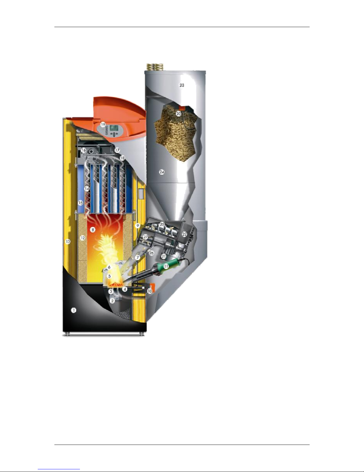
3.1 Cutaway diagram of BIOSTAR Flex
BS-03-01-00-00-01-BAEN
1. Ash box door
2. Cleaning grate
3. Primary air
4. Self-cleaning grate
5. Secondary air
6. Swirl plate
7. Burn-back inhibiting fuel chute
8. Expansion zone
9. Automatic heat exchanger cleaning
mechanism
10. Grate cleaner motor
11. Ignition fan
12. Ceramic insulation
13. Overall insulation
14. Helix baffles
15. Tube-type heat exchanger
16. Flue draught fan
17. Flue gas sensor
18. Oxygen sensor
19. Control panel (controller)
20. Sensor for fill-level indicator
21. Motor
22. Drive gear
23. Vacuum fan
24. Fuel hopper
25. Pellet auger
26. Photosensor
27. Rotary feeder
Page 12
BIOSTAR Operating instructions
12
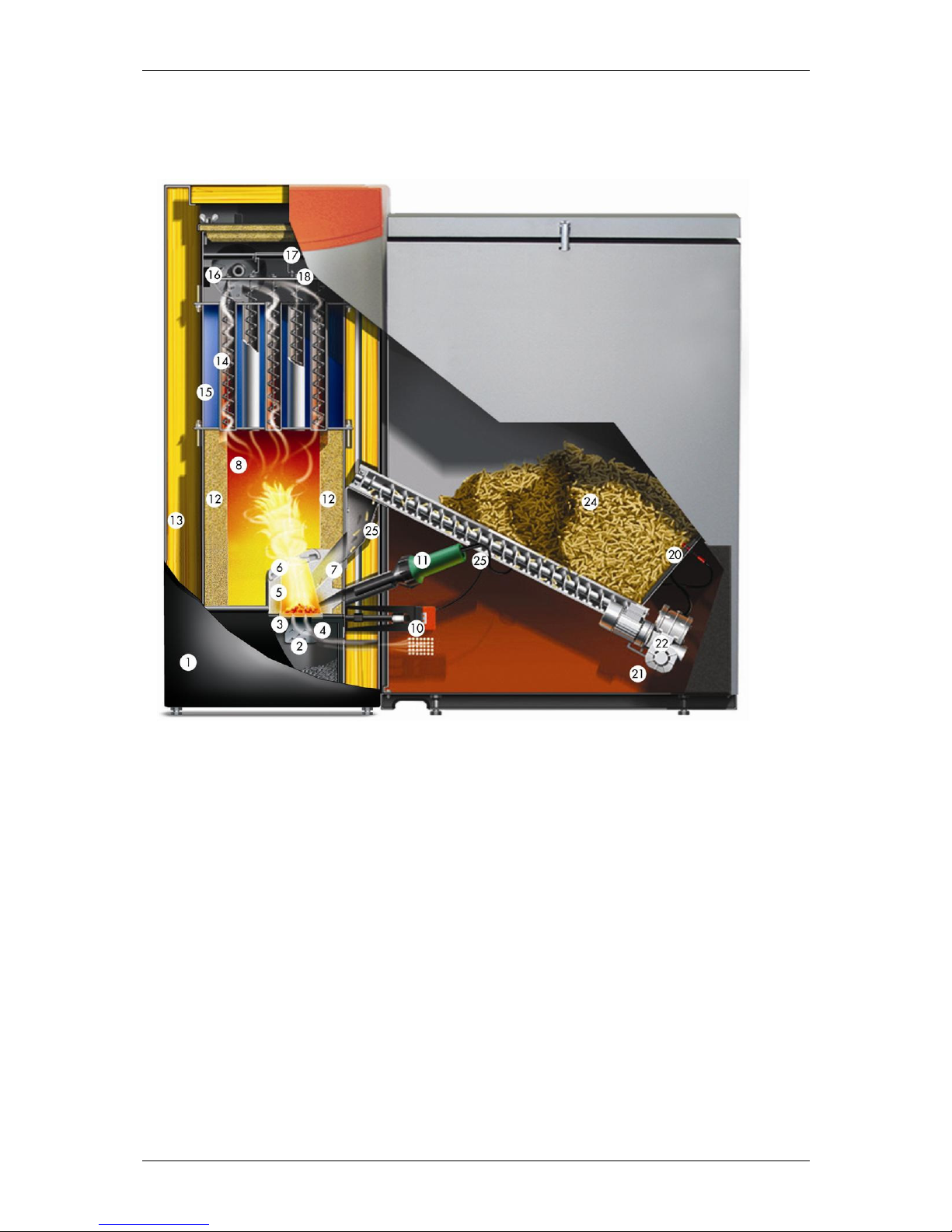
3.2 Cutaway diagram of BIOSTAR W
BS-03-02-00-00-01-BAEN
1. Ash box door
2. Cleaning grate
3. Primary air
4. Self-cleaning grate
5. Secondary air
6. Swirl plate
7. Burn-back inhibiting fuel chute
8. Expansion zone
9. Automatic heat exchanger cleaning mechanism
10. Grate cleaner motor
11. Ignition fan
12. Ceramic insulation
13. Overall insulation
14. Helix baffles
15. Tube-type heat exchanger
16. Flue draught fan
17. Flue gas sensor
18. Oxygen sensor
19. Control panel (controller)
20. Sensor for fill-level indicator
21. Motor
22. Drive gear
23. ---
24. Fuel hopper
19
9
Page 13

BIOSTAR Operating instructions
13
4 Safety systems
BS-04-00-00-00-01-BAEN
To prevent the boiler overheating, the controller reduces the
heat output in certain situations. If the boiler still threatens to
overheat, the controller responds according to a set of defined
safety levels.
Safety level 1
BS-04-00-00-01-01-BAEN
15°C above specified temperature
The drive motor stops the fuel feed system and the flue
draught fan shuts down.
Safety level 2
BS-04-00-00-02-01-BAEN
Boiler temperature above 85°C
All heating pumps and the cylinder charging pump are
switched on to carry heat away from the boiler.
Safety level 3
BS-04-00-00-01-03-BAEN
Boiler temperature above 100°C
The STL (safety temperature limiter) trips and switches all
boiler control functions off while the heating circulation pumps
continue to run. The system remains switched off even if the
boiler temperature drops back below 90 °C. The system must
not be started up again until any faults have been rectified and
the boiler has been checked.
Power failure
BS-04-00-00-04-01-BAEN
The controller, the flue draught fan and all circulation pumps
switch off due to lack of electricity if there is a power cut. The
glowing fuel bed on the grate continues burn with the natural
draught of the flue. As this operating mode is not ideal, a
larger amount of ash collects on the grate as well. As soon as
the electricity supply is restored, the controller takes control of
the heating system again.
Opening the ash box
BS-04-00-00-05-01-BAEN
• The auger motor stops feeding in fuel
• The flue draught fan switches to maximum extraction speed
• After the firebox door is closed, normal operation is
resumed or re-ignition initiated
Page 14
BIOSTAR Operating instructions
14
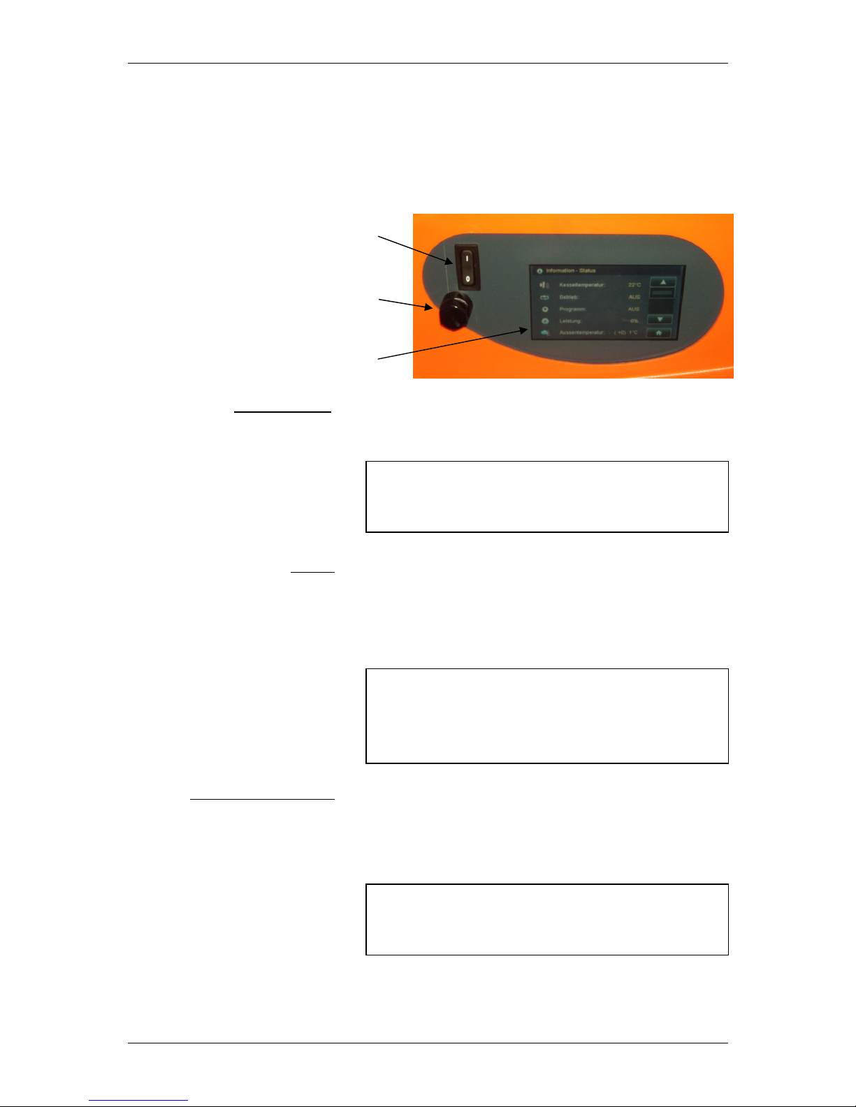
5 Control panel description
BS-05-00-00-00-01-BAEN
The appliance has a large touch-screen control panel with a
menu-based interface. All setting and query options are
shown on the display. All settings can be entered by pressing
the "buttons" on the touch screen. Any system messages are
displayed on the screen.
BS-05-00-00-01-01-BADE
1
2
3
Power switch (1)
BS-05-00-00-02-01-BAEN
Normally remains permanently switched on. The power switch
may only be switched off when the system is not in operation.
STL (2)
BS-05-00-00-03-01-BAEN
Excessive temperature (approx. 100°C) trips the safety
temperature limiter (STL) located under the cap (2); →
appliance operation is suspended; → if the STL has tripped,
identify and eliminate the cause and then press in the STL
(button) with a thin object.
Touch-screen display (3)
BS-05-00-00-04-01-BAEN
Pressing lightly with your fingertip on the relevant buttons on
the display opens the various program levels, menus and
submenus. All settings are made directly on the touch-screen
display.
Note: The system must also be disconnected from
the mains by unplugging the power lead when
carrying out repairs or servicing work.
Note: The system must not be started up again until
any faults have been rectified and the boiler
has been checked. If necessary, a heating
engineer must be called in.
Note: Never use sharp objects such as ball-point
pens or the like to operate the touch screen.
Page 15

BIOSTAR Operating instructions
15
6 Overview of menu and levels
(menu structure)
BS-06-00-00-00-01-BAEN
Fault screen
Information
Status info
Boiler info
MK Controller 0
info
Off
MK Controller 1
info
Normal
MK Controller 2
info
Hot water
Thermal store info
Heating
▲ Low
Information level
Low until
RECHARGE HW
Manual
User Level
Service level
▼
Grate cleaning
Parameters menu
▼
▼
User Level
Service level CODE User menu
Parameters menu CODE Reset data Heating circuit 0
Boiler parameters Fault list Heating circ uit 1
▲
Test program Heating circuit 2
House level
Commissioning Heating circuit 3
HC0 parameters Heating circuit 4
HC1 parameters Heating circuit 5
HC2 parameters Heating circuit 6
HC3 parameters Heating circuit 7
HC4 parameters Heating circuit 8
HC5 parameters DHW 0
HC6 parameters DHW 1
HC7 parameters DHW 2
HC8 parameters Thermal store
DHW0 Parameters Deta il View
DHW1 Parameters Date/Time
DHW2 Parameters
HP0 parameters
Note:
•
••
• Menus shown with a dashed border only appear if
activated on the Commissioning menu.
•
••
• Changes to the settings on the Service or
Parameters levels may only be made with the
agreement of GUNTAMATIC.
System settings
Layout of touch-screen display
BS-06-00-00-01-01-BAEN
Header Scroll bar Scroll buttons
Symbols Select button
The header contains information about the level or menu selected. Operating statuses, sensor
readings and switch conditions can be queried in the Selection window. The various buttons
can be used to change and save settings or switch to different levels or menus, for example.
You switch between the levels and menus by touching the buttons directly on the display
screen.
Page 16

BIOSTAR Operating instructions
16
6.1 Information level
(user)
BS-06-01-00-00-01-BAEN
You use the "DOWN" and "UP" buttons to
navigate through the Information Level menu.
1) Only shown if one or more heating circuit controllers are activated.
2) Only shown if a thermal store is integrated in the system
Fault
→ highest priority
Plain-language fault messages are displayed showing date and
time of occurrence
Fault is acknowledged by pressing "Quit" button
1)
Information
→ Only shown if the programme "Low until" has been activated
Disappears after the set time has elapsed
Can be prematurely deactivated by pressing "Quit" button
Information – Status
→ Shows boiler status
Shows boiler temperature
Shows boiler operating mode
Shows selected programme
Shows boiler output
1)
Shows outside temperature
→ Figure in brackets = average temperature
Information – Boiler
→ Shows boiler data
Shows boiler temperature
Shows CO2 level
Shows efficiency
Shows time in hours until ash warning is triggered
Shows fuel gauge
→ Fuel quantity
1)
Information – Controller 0
→ Heating circuit controller 0 (HCC 0)
Shows domestic hot water temperature and operating mode for cylinder 0
Shows operating mode for heating circuit 0
Shows operating mode for heating circuit 1
Shows operating mode for heating circuit 2
1) ▼
Information – Controller 1
→ Only shown if Heating circuit controller 1 is present
1) ▼
Information – Controller 2
→ Only shown if Heating circuit controller 2 is present
2)
Information – Thermal store
Shows thermal store temperature at top
Shows thermal store temperature at bottom
Shows thermal store pump HP0 operating mode
Shows thermal store charging programme
Page 17

BIOSTAR Operating instructions
17
6.2 House level
(user)
BS-06-02-00-00-01-BAEN
All heating programmes and menus are listed and described
below:
3) Pressing the buttons takes you to the relevant programme/level
6.3 User level
(User)
BS-06-03-00-00-01-BAEN
Depending on the system configuration, the menu levels and
submenus may contain different items.
4) Setting options on User menu
5) Thermal store timings and charging programme settings
6) Facility for querying operating modes, sensor readings and switch conditions on Detail View menu
7) Facility for viewing/setting date and time on Date/Time menu
Heating and hot water switched off
→ Anti-freeze function active
Heating and hot water on as per timer programme
Hot water as per timer programme DHW summer
→ Heating mode switched off
Heating mode
→ Day and night (hot water heating as per timer programme)
Low-temperature mode
→ Day and night (hot water heating as per timer programme)
Low-temperature mode until a specified time
→ Hot water as per timer programme
Hot water heating outside programmed charging times
→ Max. duration 90 min
Constant heating to specified boiler temperature
→ Set on User menu
Manual opening of tipper grate for cleaning purposes
3)
→ Takes you to User level
3)
→ Takes you to Service level
→ CODE required
3)
→ Takes you to Parameters level
→ CODE required
4)
User menu
→ User settings
Heating Circuit 0 menu
→ Timer controlled pump heating circuit (modulating control)
Heating Circuit 1 menu
→ Timer-controlled mixer-valve heating circuit
Heating Circuit 2 menu
→ Timer-controlled mixer-valve heating circuit
DHW 0 menu
5)
Thermal store menu
→ Thermal store settings
6)
Detail View menu
→ Boiler data and operating modes are shown
7)
Date/Time menu
Page 18

BIOSTAR Operating instructions
18
6.3.1 Heating Circuit
menu (User)
BS-06-03-01-00-01-BAEN
The Heating Circuit menu allows you to enter the settings for
the various heating circuits.
8) Options → Auto Heating circuit is switched ON/OFF according to demand and timer programme.
→ Off The heating circuit is switched off.
→ Constant The pump runs continuously; with mixer-valve heating circuits, the mixer valve is not operated
9) Modulation to "daytime required temperature" is only possible in conjunction with a room stat or room controller; raising or
lowering the required temperature shifts the heating curve up or down accordingly.
10) Modulation to "night-time required temperature" is only possible in conjunction with a room stat or room controller; in addition,
the outside temperature must be below that set in menu option "Night OFF OT" (hysteresis 2°C)
11) Options → 0% No room effect programmed
→ 25% Modulation of room temperature based 25% on room temperature and 75% on outside temperature.
→ 50% Modulation of room temperature based 50% on room temperature and 50% on outside temperature.
→ 75% Modulation of room temperature based 75% on room temperature and 25% on outside temperature.
→ 100% Modulation of room temperature based 100% on room temperature.
→ T 1°C If the required room temperature is exceeded by 1°C the heating circuit pump is switched off.
→ T 2°C If the required room temperature is exceeded by 2°C the heating circuit pump is switched off.
→ T 3°C If the required room temperature is exceeded by 3°C the heating circuit pump is switched off.
12) A higher heating characteristic figure produces a higher required flow temperature at the same outside temperature
13) If the temperature drops below the set temperature during the low-temperature phase, the boiler heats to the required night-time
temperature.
14) The set outside temperature is exceeded during the heating phase, the heating circuits are switched off.
6.3.2 Hot Water
menu (User)
BS-06-03-02-00-01-BAEN
The Hot Water menu allows you to enter the settings for the
various domestic hot water circuits.
15) Options → Auto Charging pump is switched ON/OFF according to demand and timer programme.
→ Off The charging pump is switched off.
→ Constant The charging pump runs continuously
16) All charging times programmed in the "DHW timer programme" are active when the programme is set to "Normal".
17) All charging times programmed in the "DHW summer timer programme" are active when the programme is set to "Hot Water".
18) Options → No During charging of DHW cylinder, heating circuits can be enabled.
→ Yes During charging of DHW cylinder, heating circuits cannot be enabled (factory setting =
recommended).
8)
Heating circuit control status
Facility for setting heating and low-temperature times
9)
Facility for setting daytime required temperature
10)
Facility for setting night-time required temperature
11)
Facility for setting room effect/thermostat function
12)
Facility for setting heating characteristic
13)
Changeover from low-temperature mode to night-time set temperature
14)
Outside temperature mode cut-off for heating circuits
15)
Hot water circuit control status
16)
Facility for setting hot water charging times
17)
Facility for setting summer hot water charging times
Facility for setting required hot water temperature
18)
Facility for setting hot water priority
Page 19

BIOSTAR Operating instructions
19
6.3.3 Heating Circuit
menu (User)
BS-06-03-03-00-01-BAEN
The Thermal Store HP0 menu allows you to enter settings for
thermal store management.
19) Options → Auto Thermal store pump is switched ON/OFF according to demand and timer programme.
→ Off The thermal store pump is switched off
→ Constant The thermal store pump runs continuously
20) Options → Full The thermal store is fully charged
Charging switches off when the required thermal store temperature at T3 is reached and also the
required thermal store temperature minus the parameter TSbtm-Boff (-10°C) is reached at T2
→ Part The thermal store is partially charged
Charging switches off when the required thermal store temperature is reached at T3 (= parameter
TS top-B off)
21) Thermal store only charged during charging times enabled in "Thermal store timer programme"
6.3.4 User
menu
BS-06-03-04-00-01-BAEN
Depending on the system configuration, the menus may
contain different items.
22) Higher setting = the fuel gauge counts down faster
23) Options → ECO optimum Economy mode setting (factory setting)
→ High output Setting necessitates more frequent cleaning (only use temporarily)
→ High dust Setting for low-quality pellets with high dust content
→ High clinker Setting for if high levels of clinker form in the fire box
6.3.5 Detail View
menu (User)
BS-06-03-05-00-01-BAEN
All possible system operating statuses, sensor readings and
switch conditions can be queried in Detail View. No settings
can be made on this menu. Its primary purpose is to aid
telephone diagnosis of possible fault causes and to assist the
GUNTAMATIC engineer with fault rectification.
6.3.6 Date/Time
menu (User)
BS-06-03-06-00-01-BAEN
19)
Status of special output HP0
20)
Facility for setting thermal store charging programme
21)
Facility for setting thermal store charging times
Facility for setting the thermal store required temperature
→ sensor (T3)
Facility for setting the thermal store minimum temperature
→ sensor (T3)
Menu option Ash emptied
→ Press "YES" to confirm after emptying ash box
Maximum time in hours until ash warning is triggered
→ 0h = deactivated
Enable burner
→ Setting OFF = Burner does not start up – controller remains active
Facility for resetting the fuel gauge
→ Sets counter to "0"
22)
Facility for setting average pellet size
For manually switching on drive motor G1
→ Only possible in OFF mode
For manual (vacuum) filling of fuel hopper
→ Do not interrupt process
Fuel filling lock-out time
→ Force-filling still possible
23)
Facility for setting operating mode
Menu language setting
Page 20

BIOSTAR Operating instructions
20
6.4 Service Level
(Expert)
BS-06-04-00-00-01-BAEN
CODE entry required.
Changes to the settings on the Service Level may only be
made with the agreement of GUNTAMATIC or an authorised
GUNTAMATIC engineer.
6.4.1
Service menu
Reset Data
(Expert)
BS-06-04-01-00-01-BAEN
Caution: If the service menu option "Reset Data" is
incorrectly used, reconfiguration of the entire
system may be necessary.
24) After a change of software version, only those parameters that have changed or been added in the new version are imported.
25) Caution: → All system settings including hours of duty and service interval timer readings are lost;
→ after a controller reset, the system is in the as-delivered condition;
→ the system then has to be reconfigured;
6.4.2
Service menu
Fault Screen
(Expert)
BS-06-04-02-00-01-BAEN
Service menu Reset data
→ Caution: All system settings may be lost.
Service menu Fault screen
→ Fault memory
Service menu Test program
→ Function test of all system components
Service menu Commissioning
→ Activation of all system components
Service menu HC0 Parameters
→ Parameters for HC0
Service menu HC1 Parameters
→ Parameters for HC1
Service menu HC2 Parameters
→ Parameters for HC2
Service menu DHW0 Parameters
→ Parameters for DHW cylinder 0
Service menu HP0 Parameters
→ Parameters for HP0
Service menu System settings
→ System parameters
For importing stored customer data if necessary
For saving changes to system configuration in customer data
24)
Imports only the modified parameters of a new software version
For resetting duty hours counter is to 0
For resetting service interval timer to 0
25)
Loads factory settings
→ The system then has to be reconfigured!
For resetting calibration after replacing the oxygen sensor
Plain-language fault messages are displayed showing date and time of
occurrence
Page 21

BIOSTAR Operating instructions
21
6.4.3
Service menu
Commissioning
(Expert)
BS-06-04-03-00-01-BAEN
All system components present can be programmed and
activated from the service menu Commissioning.
For setting boiler type
For setting boiler output
→ stated on rating plate
26)
Setting for outfeed system type
For activating heating circuit controller 0
For activating DHW cylinder 0
For setting the DHW charging time
→ for NORMAL programme
For setting the DHW charging time
→ for HOT WATER programme
For setting required hot water temperature
For setting hot water priority
27)
For activating Heating Circuit 0
→ Pump heating circuit (modulating control without thermal store)
Enabling temperature for Heating circuit 0
For setting maximum flow temperature for heating circuit 0
Setting for heating characteristic for heating circuit 0
For setting heating times for heating circuit 0
28)
For activating room stat or room controller for heating circuit 0
27)
For activating heating circuit 1
Enabling temperature for Heating circuit 1
For setting maximum flow temperature for heating circuit 1
Setting for heating characteristic for heating circuit 1
For setting heating times for heating circuit 1
28)
For activating room stat or room controller for heating circuit 1
27)
For activating heating circuit 2
Enabling temperature for Heating circuit 2
For setting maximum flow temperature for heating circuit 2
Setting for heating characteristic for heating circuit 2
For setting heating times for heating circuit 2
28)
For activating room stat or room controller for heating circuit 2
For activating heating circuit controller 1
→ external wall controller
For activating heating circuit controller 2
→ external wall controller
29)
For activating special output HP0
For setting vacuum pipe length
→ Set single pipe length
For first-time filling of fuel hopper
→ Do not interrupt process
For starting drive motor G1
→ Fill stoker auger
After completing system configuration → save customer data
Page 22

BIOSTAR Operating instructions
22
26) Options → FLEX Vacuum outfeed from a storeroom
→ BOX Vacuum outfeed from a fabric hopper
→ HX Auger outfeed from a storeroom
→ B/HOP Auger outfeed from a boiler-mounted hopper
27) Options → None Heating circuit is deactivated
→ Pump The heating circuit pump will be controlled by the timer programme
→ Mixer The heating circuit pump and the mixer valve will be controlled by the timer programme
28) Options → None No room stat connected
→ RFF Analogue room stat is connected
→ RS Full Digital room controller is connected (facility for setting all heating circuits)
→ RS HC Digital room controller is connected (facility for setting assigned heating circuit only)
29) Options → None Output HP0 is deacti vated
→ F pump Pump HP0 is operated as a feeder pump (only activate with heating circuit controller)
→ Th/store pump Pump HP0 is operated as thermal store charging pump
→ Pump Pump HP0 is operated as a pump (only activate without heating circuit controller)
→ FSO Fault signal output (230 V AC)
6.4.4
Service menu
Heating Circuit/Screed Drying Programme Parameters
(Expert)
BS-06-04-04-00-01-BAEN
Options for setting the heating circuit and screed drying
parameters:
CAUTION: The screed drying parameters must be set in consultation
with the floor layer.
Maintaining the specified temperatures is not possible in
modulating control mode but only when using automatic mixer
valves. Maintenance of the specified temperatures cannot be
100% guaranteed – due to various safety circuits and special
boiler functions, in exceptional cases the temperatures can be
significantly exceeded. If that is a problem in terms of damage
to building work, the screed drying function should be
operated manually.
30) After activation of the screed drying programme, the menu expands to reveal the screed programme parameters.
Heating circuit operating status
Room stat setting
For setting mixer valve running time
For setting minimum flow temperature
For setting maximum flow temperature
For setting boiler overcompensation
→ added to required temp. = required boiler temp.
Enabling temperature for Heating circuit 1
For setting heating characteristic parallel shift
30)
For activating screed drying programme
Screed prog. →
For setting the flow temperature increment
Screed prog. →
For setting time until next flow temperature increase
Screed prog. →
For setting minimum flow temperature
Screed prog. →
For setting maximum flow temperature
Screed prog. →
For setting holding time for maximum flow temperature
Screed prog. →
For starting the screed drying programme
Page 23

BIOSTAR Operating instructions
23
6.4.5
Service menu
Hot water parameters
(Expert)
BS-06-04-05-00-01-BAEN
Facility for setting hot water parameters
31) If the temperature in the hot water cylinder falls 10°C (hysteresis) below the required temperature, the hot water cylinder is
heated up again; the precondition is that the charging time is enabled in the timer programme on the "Hot water" menu.
6.4.6
Service menu
HP0 parameters
(Expert)
BS-06-04-06-00-01-BAEN
Facility for setting the parameters for special output HP0
32) Function → TS top B ON The boiler is started up when the thermal store temperature falls below the maximum
temperature required by the heating circuit controller minus the temperature set in the parameter
"TS top B ON"
Example: Maximum temperature required by heating circuit controller = 55 °C
Setting for "TS top B ON" = 6°C
The boiler starts up when the temperature at the thermal store top sensor (T3)
is 49°C
33) Function → TS top B OFF The boiler is shut off when the temperature at the thermal store top sensor (T3) reaches the
thermal store required temperature plus the temperature set for the parameter "TS top B OFF"
Example: Required thermal store temperature = 60°C
Setting for "TS top B OFF" = 5°C
The boiler is shut off when the temperature at the thermal store top sensor (T3)
is 65°C
34) Function → TS btm B OFF The boiler is shut off as soon as the temperature at the bottom of the thermal store (T2)
only differs from the temperature at the top of the thermal store (T3) by the amount set for the
parameter "TS btm B OFF".
Example: Temperature at top of thermal store (T3) = 60 °C
Setting for parameter "TS btm-B off" = -10 °C
The boiler is shut off when the temperature at the thermal store bottom sensor
(T2) is 50°C
Hot water circuit operating mode
31)
Facility for setting hot water hysteresis
→ Hot water cylinder recharging
Enabling temperature for cylinder charging pump
→ CCP 0
For setting boiler overcompensation
→ added to required temp. = required boiler temp.
Operating status of special output HP0
Enabling temperature for output HP0
32)
Setting for thermal store top – boiler ON
33)
Setting for thermal store top – boiler OFF
34)
Setting for thermal store bottom – boiler OFF
Setting for temperature difference between boiler and bottom of thermal store
Page 24

BIOSTAR Operating instructions
24
6.4.7
Service menu
System settings
(Expert)
BS-06-04-07-00-01-BAEN
Facility for setting special boiler and system parameters
35) Options → None No oxygen sensor or oxygen sensor is deactivated
→ NGK Oxygen sensor type fitted is NGK
→ BOSCH Oxygen sensor type fitted is BOSCH
36) Options → Auto The oxygen sensor heater is switched on/off according to operating mode
→ Constant The oxygen sensor heater is permanently switched on
(Oxygen sensor heater does not switch off until boiler has been in "OFF" mode for more than 50 h)
37) Options → Terminal Data querying via Windows hyper terminal/display
→ DAQ Data querying via online recorder (only usable at factory)
→ GSM module Data querying, information messages and boiler control via GSM module
For setting system type
→ stated on rating plate
For setting boiler type
→ stated on rating plate
For setting outfeed system type
Automatic de-ashing
→ On systems with integral ash box, set to "Off"
For setting heating circuit controller 0
For setting heating circuit controller 1
→ external wall controller
For setting heating circuit controller 2
→ external wall controller
Outside-temperature sensor activation/deactivation
Fuel setting
→ Setting 1 = 15 kW, setting 2 = 23 kW
For photo-cell activation/deactivation
→ Combustion monitoring
For activating photoresistor calibration
For entering photoresistor compensation
35)
For setting oxygen sensor type
36)
For setting oxygen sensor heater
For activating oxygen sensor calibration
For entering oxygen sensor compensation
For setting oxygen sensor characteristic
→ only during "Controller" mode
37)
For activating monitoring mode
Facility for data recording on SD memory cards
Facility for reading data from SD memory cards
For querying manufacturer code
Setting for fault signal from tipper grate motor position monitor
Setting for fault signal from speed monitor for drive motor G1
Setting for fault signal fuel level sensor
Setting for fault signal "Empty ash box"
→ 0h = Deactivated
For activating filling sequence
→ only in OFF mode – do not interrupt
Setting for flue draught fan operation
For selecting drive motor type
For selecting flue draught fan blade type
All pumps are activated once a week for the time set here
Activates all heating circuits up to maximum flow temperature
Pump HP0 continues running until temperature at boiler is below set temperature
If the outside temperature falls below "HCP A/F outside", the heating circuit pumps start running
"HCP A/F Flow" is required flow temperature
→ only in "OFF" mode
Raises boiler temperature until STL trips
→ in Controller mode
Page 25

BIOSTAR Operating instructions
25
7 User Settings
BS-07-00-00-00-01-BAEM
7.1 Activating a heating programme
BS-07-01-00-00-01-BAEN
To set the "NORMAL" programme, proceed as set out below,
step by step:
After activating the "NORMAL" heating programme, check the
selected programme on the "Status information" screen. As
soon as heat is called for and there is sufficient heat in the
thermal store, the heating circuits start up fully automatically.
1) → Press the "House level" button
The programme currently selected, "Off", is shown in the header
2) → Press the "Normal" button
The new programme selected, "Normal", is now shown in the header
3) → Press the "Info" button
4) → The "Normal" programme is now shown on the "Status information"
screen
Page 26

BIOSTAR Operating instructions
26
7.2 Deactivating a heating programme
BS-07-02-00-00-01-BAEN
To set the "NORMAL" programme to "OFF", proceed as set
out below, step by step:
After deactivating the "NORMAL" heating programme, check
the selected programme on the "Status information" screen.
1) → Press the "House level" button
The programme currently selected, "Normal", is shown in the header
2) → Press the "Off" button
The new programme selected, "Off", is now shown in the header
3) → Press the "Info" button
4) → The "Off" programme is now shown on the "Status information" screen
Page 27

BIOSTAR Operating instructions
27
7.3 Setting a timer programme
BS-07-03-00-00-01-BAEN
The heating circuits/charging pumps can only be called into
action during the times enabled in the timer programme.
The example set out below illustrates programming the timer
programme for heating circuit 1:
7.3.1 Programming en bloc
BS-07-03-01-00-01-BAEN
En bloc programming can be used to programme the same on
and off times for every day of the week.
1) → Press the "House level" button
2) → Press the "User level" button
3) → Press the "Heating circuit 1" button
4) → Press the "Timer programme 1" button
5) → Press the button for the day of the week to be set
6) → Press the "ON" or "OFF" time to be altered
7) → Use the and buttons to set the time
8) → To save the setting, press the button
To activate programming en bloc, press the same weekday button twice in
succession; all days are then highlighted and can be programmed
collectively to the same times
Page 28

BIOSTAR Operating instructions
28
7.4 Changing the heating characteristic
BS-07-04-00-00-01-BAEN
The heating circuits/charging pumps can only be called into
action during the times enabled in the timer programme.
The example set out below illustrates programming the
heating characteristic for heating circuit 1:
Heating characteristic graph
1) → Press the "House level" button
2) → Press the "User level" button
3) → Press the "Heating circuit 1" button
4) → Press the "Heating characteristic 1" button
5) → Use the and buttons to set the heating characteristic
6) → To save the setting, press the button
20
30
40
50
60
70
80
-20-15-10-505101520
Außentemperatur [°C]
Vorlauftem peratur [°C]
0,5
1,0
1,5
2,02,53,03,5
Page 29

BIOSTAR Operating instructions
29
7.5 Changing the required hot water temperature
BS-07-05-00-00-01-BAEN
You can change the required hot water temperature on the
Hot Water menu.
The example set out below illustrates programming the
required temperature for DHW cylinder 0:
1) → Press the "House level" button
2) → Press the "User level" button
3) → Press the "DHW cylinder 0" button
4) → Press the "DHW required temp 0" button
5) → Use the and buttons to set the required temperature
6) → To save the setting, press the button
Page 30

BIOSTAR Operating instructions
30
7.6 Analogue room stat
BS-07-06-00-00-01-BAEN
If your system is fitted with an outside-temperature based
heating circuit controller, each heating circuit can be equipped
with an analogue room stat if desired.
The control knob on the room stat allows adjustment of the
required room temperature preset on the Heating Circuit
menu. Setting the control to a position in the positive range (+)
raises the room temperature by up to 3°C. Setting it to a
position in the negative range (–) lower lowers the room
temperature by up to 3°C.
Note: This means that the room temperature shown in
the Detail View will be inaccurate. The room
temperature shown will only match the actual
temperature when the control knob is in the
centre position.
Operating modes
Low: Low-temperature mode → if, during the low-
temperature phase, the outside temperature falls
below the temperature set in the parameter
"Night OFF OT", the system heats to the room
temperature set in the parameter "Night-time
Required Temperature".
Normal: Heating and low-temperature modes on as per
timer programme
Heating: Continuous heating to "Required Daytime
Temperature"
Installation site Fix the room stat on an internal wall at a height of approx. 1m
- 1.5m. The most effective room is the one that is most
frequently occupied. In that room, the radiators must not be
fitted with thermostatic radiator valves (valves must be fully
turned on).
Note: The room stat should not be fitted in a position
where it will be exposed to warm sunshine or the
heat from a stove.
Connection Pull off the control knob from the front, undo the fixing screw
and remove the casing from the front.
Wire the room stat to terminals 1 and 2.
7.7 Digital room controller
BS-07-07-00-00-01-BAEN
An instruction manual is supplied with the room controller.
A maximum of 3 room controllers can be connected to the
system.
Connection is established via the CAN bus.
Page 31

BIOSTAR Operating instructions
31
8 Operating the heating system
BS-08-00-00-00-01-BAEN
8.1 Starting up/Shutting down the system
BS-08-01-00-00-01-BAEN
BS-08-01-00-01-01-BAEN
Initial commissioning Initial commissioning and basic adjustment of the system may
only be carried out by GUNTAMATIC engineers or authorised
GUNTAMATIC agents.
BS-08-01-00-02-01-BAEN
Restarting Before starting up the system again in the autumn/winter,
carry out the annual check of the control and safety systems
to ensure they are safe and functional. We recommend that
you take out a maintenance contract so that the system
operates safely and economically.
BS-08-01-00-03-01-BAEN
Day-to-day operation Clean the heating system precisely according to the
instructions in the section Cleaning/Care. The amount of
cleaning work required is heavily dependent on the quality of
the fuel used and lower-quality fuels may necessitate more
cleaning work.
BS-08-01-00-04-01-BAEN
Shutting down the system The system only needs to be shut down at the end of the
heating season, if faults occur or in order to refill the fuel store.
To do so, set the system to the programme "OFF" and allow it
to cool down for approx. 120 minutes. The system can then be
shut down.
If the system is not used for extended periods (summer) also
isolate it from the power supply by disconnecting the mains
plug in order to prevent unnecessary lightning damage.
8.2 Heating system checks
BS-08-02-00-00-01-BAEN
BS-08-02-00-01-01-BAEN
Checking system pressure The operating pressure is normally between 1 bar and 2.5 bar.
If the system pressure is too low, malfunctions may result. If
necessary top up the water in the heating system.
Note Completely draining and refilling the system or
topping up a system filled with anti-freeze or treated
water must only be carried out by a heating
engineer.
Topping up the heating system water
• The heating system water must be cold when topping up
→ make sure the heating system water temperature is
below 40°C.
• Add water slowly until the required system pressure is
indicated on the system pressure gauge.
• Bleed the heating system.
• Check the system pressure again and add more water if
necessary.
BS-08-02-00-02-01-BAEN
Pressure-relief valve Turn the red knob on the safety set; → check for leaks and
correct operation; → in the event of malfunctions or leaks, call
in your installer or heating engineer.
BS-08-02-00-03-01-BAEN
Expansion vessel If there are large pressure fluctuations between when the
heating system is hot and cold, check the charge pressure in
the expansion vessel; → in the event of malfunctions or leaks,
call in your installer or heating engineer.
BS-08-02-00-04-01-BAEN
Boiler room ventilation Check that the air supply vents/ducts are clear.
Page 32

BIOSTAR Operating instructions
32
8.3 Fuel quality
BS-08-03-00-00-01-BAEN
To ensure trouble-free heating with the boiler, the fuel must be
of the right quality.
Ensuring fuel quality
BS-08-03-00-01-01-BAEN
Austria: Always order pellets conforming to
ÖNORM M 7135
Germany: Always order pellets conforming to
DIN 51731
Switzerland: Always order pellets conforming to
SN 166000 and carrying the Swisspellets
mark.
Note: Dust emission from the boiler flue is heavily
dependent on the dust content of the fuel.
Page 33

BIOSTAR Operating instructions
33
8.4 Fuels
BS-08-04-00-00-01-BAEN
8.4.1 Pellets
BS-08-04-01-00-01-BAEN
There are a number of points to observe when ordering wood
pellets in order to ensure that they are of perfect quality.
Reliable and trouble-free operation of the boiler and the
conveying systems can only be guaranteed with high-quality
pellets. Therefore we strongly advise that only quality-assured
products are used that are guaranteed as such by the
manufacturer.
Important quality criteria
• Lowest possible dust content
• Surface should be shiny and very hard
• No additives or binding agents
• The ideal length is 20 mm
The price should always be a secondary consideration after
the quality criteria. If the required quality criteria are not met,
problems with combustion or conveying, increased wear and
pellet consumption can result. Therefore, you should not
accept quality standards that do not meet the above
requirements.
Properties
Calorific value 4.9 kWh/kg
Bulk weight >650 kg/m³
Pellet size (length) 5 - 30 mm
Pellet diameter 5 - 6 mm
Water content 8 – 10 %
Ash content < 0.5%
8.5 Fuel storage
BS-08-05-00-00-01-BAEN
As a general rule, wood pellets should be stored in absolutely
dry storerooms. Those rooms can be fitted with pressure-filling
and air extraction pipes (Type A/110/DIN14309/G4 ½") or be
provided with a filling hatch and must be fire-rated to Class
F90. The fire door must be protected by removable wooden
boards. The wall opposite the pressure-filling pipe is to be
protected by a blast guard. Alternatively, the pellets can be
stored in fabric hoppers or plastic outdoor tanks.
Note: If pellets come into contact with water, they
swell up and disintegrate.
Therefore, the storeroom must be absolutely dry.
Page 34

BIOSTAR Operating instructions
34
8.6 Filling/refilling the fuel store
BS-08-06-00-00-01-BAEN
BS-08-06-00-01-01-BAEN
BS-08-06-00-02-01-BAEN
Vacuum systems When first filling the storeroom and every time it is refilled after
being completely emptied, do not immediately fill the store
completely. Instead, the fuel auger should first be filled with
pellets up to a depth of approx. 10 cm over its entire length.
The fuel storeroom can then be filled up to the maximum
permissible bulk storage height.
Emergency filling:
If automatic refilling of the fuel hopper should not be possible
due to a fault on the fuel store outfeed system, the fuel hopper
can be refilled manually as an "emergency" measure.
Before you do so, however, first try to rectify the fault by
consulting the section "Rectifying faults" or the section
"Information messages and fault codes" in the operating
instructions.
Procedure:
Set the system to the "OFF" programme and wait until it
switches to "OFF" mode. Then switch off the system on the
control panel by setting the power switch to "0". Unscrew the
top of the fuel hopper and fill it by hand – this is best done
from a sack of pellets. Afterwards, refit the hopper cover so
that it is tightly sealed, cancel the fault messages, set the
boiler to the heating programme and start up the system
again.
Maximum bulk storage height
Pellets max. 2.5 m bulk storage height
BS-08-06-00-03-01-BAEN
Boiler-mounted hopper The boiler-mounted hopper can be opened by pulling on the
catch. The system detects that the hopper has been opened
and shuts off the pellet auger/sets the flue draught fan to full
speed. The hopper can be filled with pellets up to the edge of
the seal. Lock the hopper cover again and operation will be
automatically resumed. Once a year the hopper should be
completely emptied and dust deposits completely vacuumed
out.
Caution: The heating system must be set to "Off" mode
at least one hour before the fuel store is filled.
On no account must the fuel store be filled
while the heating system is in operation!
Note: The fuel outfeed conveyor must be completely
emptied (vacuumed out) every 3 years at
least.
Page 35

BIOSTAR Operating instructions
35
8.7 Emptying the ash
BS-08-07-00-00-01-BAEN
The ash box has to be regularly emptied according to the
amount of fuel used, its quality and heat output. The higher
the dust content of the fuel, the shorter the intervals at which
the ash must be removed. That is particularly the case with
low-quality fuels with a high dust content.
The accumulated ash obviously contains the residues of the
fuel in concentrated form. If you only use environmentally safe
fuels, the ash residue represents a high-quality mineral
fertiliser.
BS-08-07-00-01-01-BAEN
Procedure Set the system to "Off" mode and wait until the status display
changes to "Off" mode. Unfasten the ash box by lifting the
handle upwards and pull the ash box out to the front. The
display on the control panel shows the message "Ash box
open (F01)".
After emptying the ash box, check the ash box gasket for wear
and correct seating, slide the ash box back in the boiler and
lock it in position by pressing the ash box handle firmly
downwards. The message "Ash box open (F01)" disappears
again.
Ensure the ash box is properly sealed.
On the Programme menu, set the system to the desired
heating programme (NORMAL, HEATING, etc.) and the
system will start up again.
BS-08-07-00-02-01-BAEN
Resetting the ash warning If the ash warning appears on the display, it has to be reset on
the "User" menu. To do so, go to the "User" menu and select
the option "Ash emptied", change the setting to "YES" and
press the "OK" button to confirm. The ash warning has now
been reset to the maximum number of hours before it is next
triggered. The time until the ash warning is issued is preset
and can be adjusted to suit the fuel being used by selecting
"Ash Warning" on the User menu on the User Level.
Danger: Glowing embers can cause fires.
Only deposit or store the ash from the boiler
in non-combustible sites.
Page 36
BIOSTAR Operating instructions
36
9 Cleaning/Care
BS-09-00-00-00-01-BADE
BS-09-00-00-01-01-BAEN
BS-09-00-00-02-01-BAEN
Cleaning The sophisticated cleaning system on a GUNTAMATIC
heating system means that regular cleaning work is
substantially reduced. All that is required is regular emptying
of the ash.
The flue must be regularly swept. At the same time, the flue
connecting pipe, the flue gas box and the boiler heat
exchanger should be cleared of fly-ash.
Depending on how dirty the boiler becomes (which is
determined by the quality of the fuel burned), interim cleaning
may be required, for which the precise procedure is described
in the section "Interim cleaning".
Depending on the load on the heating system, complete
cleaning – for which the precise procedure is described in the
section "Complete cleaning" – may be required twice a year
but should be carried out at least once a year.
If the heating system is subject to exceptionally high loads,
more extensive cleaning may be required.
BS-09-00-00-03-01-BAEN
Care If the casing panels or the controls become dirty, they are best
cleaned with a soft, damp cloth. Use only gentle, solvent-free
cleaners to dampen the cloth. On no account should solvents
such as alcohol, white spirit or thinners be used as they will
attack the surface of the boiler.
9.1 Cleaning the fuel store
BS-09-01-00-00-01-BAEN
The fuel outfeed auger and the fuel store must be completely
emptied (vacuumed out) at least once every 3 years so as to
prevent problems with the outfeed system due to dust
accumulation.
Note:
For safety reasons you must only carry out
servicing and cleaning when the heating
system is switched off and disconnected from
the mains, and has cooled down.
Servicing work inside the fuel storeroom must
only be carried out under the supervision of a
second person, who must be outside the
storeroom.
There is a risk that accumulation of
carbon monoxide in the fuel storeroom
could endanger your life.
In particular, you should follow the safety
instructions in Section 2.
Page 37

BIOSTAR Operating instructions
37
9.2 Interim cleaning
BS-09-02-00-00-01-BAEN
The ash box has to be emptied and interim boiler cleaning
carried out at intervals depending on the amount of fuel used.
How often interim cleaning is required can vary from every 2
weeks to every 3 months. The frequency of the cleaning work
required is essentially dependent on the quality of the fuel. A
higher fuel dust content necessitates more frequent cleaning.
Carry out the following steps for interim cleaning:
1. Set the system to the programme "OFF" and allow it to
cool down for at least 1 hour.
2. Open the casing door (1), pull out the ash box (2) to the
front and empty it.
Risk of fire from glowing embers in the ash
3. Scrape off the ash above the swirl plate in the boiler burnout zone using the fire box poker (3). Introduce the fire
box poker through the left ash box opening (4).
4. On the "House level" menu, start the programme "Clean
grate" and allow the tipper grate (5) to swing down. Do not
carry out any cleaning operations while the tipper grate is
moving.
Risk of injury from moving parts.
5. Use the cleaning tools supplied to clean the grate surface
(5) and "scrape" deposits cleanly off the grate. Also check
the grate holes and clean them out if required.
6. Remove all remaining ash from the ash chamber (6)
below the fire box. Slide the ash box back into the ash
chamber and seal it tightly.
7. On the "User" menu, set the parameter "Ash emptied" to
"Yes" and select "OK" to confirm.
8. Then select the desired heating programme, e.g.
"NORMAL", and start up the boiler. The controller takes
over control of the boiler again and switches to fully
automatic operation.
3
4
3
5
6 6
1
2
Page 38

BIOSTAR Operating instructions
38
9.3 Complete cleaning
BS-09-03-00-00-01-BAEN
Depending on the load on the heating system, complete
cleaning may be required twice a year but should be carried
out at least once a year.
Carry out the following steps for complete cleaning:
1. Set the system to the programme "OFF" and allow it to
cool down for at least 2 hours.
2. Carry out steps 2 - 8 of the interim cleaning procedure.
Before opening, isolate the system from the mains.
3. Open the flue box (7) on the top of the boiler and remove
the fan cover plate (8) by sliding it upwards.
4. Using an ash vacuum, clean out all ash from the flue
draught fan (10), between the heat exchanger tubes (9)
and in the flue connecting pipe.
Risk of fire from glowing embers in the ash
5. Check that the oxygen sensor (12) is firmly seated and, if
necessary, remove it, carefully clean it with a soft brush
and refit it. Make sure the oxygen sensor is firmly seated.
6. Remove the photo-cell (13) and clean it with a soft cloth.
Remove the inspection cover (14) and check whether the
inner surface of the chute is free of deposits. If necessary,
scrape off using the chute cleaner (15). Afterwards, refit
the inspection cover and re-insert the photo-sensor in the
socket.
7. On the "House level" menu, start the programme "Clean
grate" and allow the tipper grate (5) to swing down. Do not
carry out any cleaning operations while the tipper grate is
moving. With the tipper grate open, inspect the surface of
the fire box and clean it with the chute cleaner if
necessary.
Risk of injury from moving parts.
8. Check that the tipper grate (16) forms an air-tight seal with
the fire box opening.
9. Clean out all remaining ash from the ash chamber (17) on
the left and right using the poker then refit the ash box
and seal it tightly.
10. Then select the desired heating programme, e.g.
"NORMAL". The controller takes over control of the boiler
again and switches to fully automatic operation.
7
8
9
10 11
12
13
14
15
16
17 17
Page 39

BIOSTAR Operating instructions
39
10 Rectifying faults
BS-10-00-00-00-01-BAEN
Fault Cause/Function Remedy
Control panel cannot be
switched on
• Power supply disconnected
• Fuse blown
• Check external mains plug and/or power
supply lead between circuit boards
• Check fuse in supply lead and on the
control panel circuit board
Smoke escaping into
boiler room
• Flue pipe leaking
• Flue draught regulator unfavourably
positioned
• Flue not clear or not providing any
draught
• Eliminate leaks
• Consult flue installer
• Check flue
Heat output too low
• Boiler very dirty
• Heating system inadequately
balanced
• Boiler priority active
• Flue draught in chimney flue too low
• Carry out complete cleaning
• Balance heating system and heating
pumps
• Wait until boiler charging has finished or
deactivate boiler priority
• Increase flue draught in chimney flue if
necessary
Detonation
• Detonation is only possible if the
firebox is overfilled.
• Carry out complete cleaning or consult
engineer if necessary
Difficult to limit output
• Flue draught is too great
• Wide demand fluctuations on the
part of heating system components
• Re-adjust flue draught regulator
• Stagger heating system component
demand over time
Overheating
Fault code F04
STL tripped
• The amount of heat produced
cannot be dissipated. It may be that
a heating pump has failed or has
not started up.
• Ensure heat dissipation by switching on
pumps, opening mixer valves or turning
on hot water taps.
• The cause of the boiler overheating must
be identified (if it happens frequently a
heating engineer should be called in).
• Check fuses on the boiler circuit board
Drive motor too noisy
• Hopper misaligned
• Noise transmission
• Re-align hopper
• If necessary, place the adjustable feet of
the boiler on rubber pads
Fan too noisy
• Fan is dirty
• Fan or blades loose
• Noise created by bends or rigid
connecting pipe junctions with
chimney flue
• Fan bearing defective
• Clean fan
• Eliminate cause
• Fit insulators/sleeves
• Order replacement motor
Page 40

BIOSTAR Operating instructions
40
11 Information/Fault messages
BS-11-00-00-00-01-BAEN
No. Category Origin Message Cancellation
Possible causes
F01 Note Input TKS1 open (door switch) Ash box open
(F01)
Automatic
Door switch defective,
connector faulty, ash box
open
F02 Fault Tipper grate unable to move
into position within 200 sec
(from activation)
Tipper grate unable to
attain position. Inspect
grate
(F02)
Reset button
Ash chamber too full, servo
motor defective, faulty
connection
F04 Fault Boiler temperature too high
(above parameter "BTW")
Boiler temperature too
high. Check flue draught
and boiler sensor.
(F04)
Reset button
Boiler or pump malfunction,
boiler sensor defective or
switch fault
F05 Fault
(NS)
Flue gas sensor > in "control
mode" > after time param. "X25"
> FGT + ½ BT is less than
param. "FGTb" betw. 30 and
100%
Combustion fault. Check
grate, fuel chute and
pellets.
(F05)
Reset button
No fuel, fuel chute overfilled,
incorrect flue draught,
defective flue gas sensor
F06 Fault
(NS)
Photo-sensor via param. "FW"
via time param. "Tübf"
Fire box overfilled. Check
grate, fuel chute and
pellets.
(F06)
Reset button
No fuel, fuel chute overfilled,
photo-sensor not in position
F07 Fault
(NS)
Flue gas sensor > in "ignition
mode" no FGT increase after
time parameter "X2"
Ignition not possible.
Check grate and pellet
supply
(F07)
Reset button
No fuel, fuel hopper not filled,
faulty ignition fan, faulty
connection
F08
Entry in
fault memory
With vacuum outfeed, fill level
not below limit after conveyor
running time "RT G1 min"
Fill level sensor not
reacting
(F08)
None
Fill level sensor dusty or
defective
(terminals 28-30)
F09 Note
Fill-level switch open with
vacuum outfeed
Fill level below limit.
Replenish pellets.
(F09)
Automatic
Check connection
(terminals 28-30)
F12 Fault No response from Hall-effect
sensor G1 within time param.
"Tsafe G1"
Drive motor G1 jammed
(F12)
Reset button
Fuel chute overfilled, drive
unit jammed, connection
faulty (test programme)
F16 Fault STL tripped Caution
High-temperature STL
tripped
(F16)
Press STL,
Reset button
Boiler or pump malfunction,
check fuses,
STL test
F19 Note Param. "O2 sensor comp" or
adjusted setting above the limits
of param. "mV top" or "mV btm"
Oxygen sensor readings
above limits. Check
(F19)
Reset button
Oxygen sensor dirty or
defective, carry out oxygen
sensor test, clean sensor
F20 Note
If TKS2 sends no signals during
cleaning
Ash box full or auto
cleaning mech. jammed
(F20)
Reset button
Ash box full, objects in the
ash auger, de-ashing motor
jammed or TKS2 defective
F21 Fault
(NS)
Fault F05 via oxygen sensor
(due to prior O2 sensor off = G1
off)
Flue gas error due to O2
sensor off –
Oxygen sensor test
(F21)
Reset button
Oxygen sensor reading
incorrect, connection faulty,
check flue draught, FGT too
low
F22 Note Fill level not reached within the
time "Outfeed max" .
Fill level not reached.
Check vacuum system
(F22)
Reset button
No fuel, fill level sensor
defective, vacuum pipes
clogged, vacuum system not
air-tight, vacuum unit
defective, outfeed motor
jammed
F23 Notifi-
cation
(fault)
Ash box not emptied within set
emptying interval
Empty ash box
(F23)
Reset button
Ash box not emptied or
counter not reset
Page 41

BIOSTAR Operating instructions
41
12 Replacing fuses
BS-12-00-00-00-01-BAEN
Fuse function is indicated on the relevant electrical wiring
diagrams in the installation instructions.
Replacing fuses
1. Set the system to the programme "OFF" and allow it
to cool down for at least 10 minutes.
2. Switch the Power switch to "0" and unplug the mains
plug on the back of the boiler to fully disconnect it
from the power supply.
3. Unfasten the controller cover and remove it.
4. Locate the defective fuse with the aid of the wiring
diagram in the installation instructions and replace it.
5. Press in the fuse holder 2-3 mm using a mediumsized screwdriver and turn it half a turn anticlockwise
to release it. The holder and fuse will then pop out a
few mm.
6. Remove the blown fuse and replace with a new one.
7. Insert the fuse holder, press it in 2-3 mm and secure
it in position by turning it half a turn clockwise.
Danger: Repair work may only be carried out
by authorised technicians.
Touching live electrical components can
cause fatal injury.
Even when the Power switch is "OFF" some
components of the system are still live.
Therefore, when carrying out repair work it is
imperative that the power supply is
disconnected by means of the "mains plug" or
a circuit breaker.
Page 42

BIOSTAR Operating instructions
42
BS-00-00-00-01-13-BAEN
LOG BOOK
for
AUTOMATIC WOOD-BURNING BOILER SYSTEMS
as required by the Austrian Technical Directive H118
on Preventative Fire Safety
Please note: a log book is not legally required in the UK however it is recommended that one be kept.
System operator: ……………………………………………………………………....
……………………………………………………………………....
……………………………………………………………………....
System installer: ……………………………………………………………………....
……………………………………………………………………....
……………………………………………………………………....
Boiler system:
Make:
………………..
………………………………………………….
Type:
………...
…….....………………………………………………….
Year manufactured: ……………………………………………………………………….
Heating output: ……………………………………………………………………….
Page 43

BIOSTAR Operating instructions
43
The following checks are to be carried out regularly on the automatic wood-burning boiler
system by the system operator when it is in operation:
12.1 Weekly visual inspection:
Once a week the entire boiler system including the fuel store is to be visually inspected. Any
deficiencies identified are to be rectified immediately.
12.2 Monthly checks:
The following monthly checks are to be carried out and, if a log book is maintained, should be
recorded in the log book:
• Flue gas passages clean (flue gas channels in boiler, flue connecting pipe and smoke
trap)
• Controller functioning properly
• Fault indication/warning system(s) functioning properly
• Combustion air and flue draught fans functioning properly
• Firebox in good order
• Portable fire extinguisher ready for use
• Correct storage of ash
• No combustibles stored in boiler room
• No accumulation of combustible deposits on roof
• Fire safety closures (fire doors self-closing)
12.3 Servicing:
The heating system must be serviced and inspected in accordance with the regional, local and
statutory regulations of the country of use.
We recommend that a maintenance contract is taken out providing for annual servicing by an
authorised technician.
Page 44

BIOSTAR Operating instructions
44
Year:
…………………………….
System operator:
……………………………………............................................
Serviced by:
……………………………………………………………………………………………..
Monthly
Check
Jan Feb Mar Apr May Jun Jul Aug Sep Oct Nov Dec Remarks
Flue gas passages
Controller
Warning system(s)
Fans
Firebox
Portable fire extinguisher
Ash storage
Items stored in boiler room
Deposits on roof
Fire safety closures
Smoke trap cleaning
Signature/initials
Page 45

BIOSTAR Operating instructions
45
Year:
…………………………….
System operator:
……………………………………............................................
Serviced by:
……………………………………………………………………………………………..
Monthly
Check
Jan Feb Mar Apr May Jun Jul Aug Sep Oct Nov Dec Remarks
Flue gas passages
Controller
Warning system(s)
Fans
Firebox
Portable fire extinguisher
Ash storage
Items stored in boiler room
Deposits on roof
Fire safety closures
Smoke trap cleaning
Signature/initials
Page 46

BIOSTAR Operating instructions
46
Year:
…………………………….
System operator:
……………………………………............................................
Serviced by:
……………………………………………………………………………………………..
Monthly
Check
Jan Feb Mar Apr May Jun Jul Aug Sep Oct Nov Dec Remarks
Flue gas passages
Controller
Warning system(s)
Fans
Firebox
Portable fire extinguisher
Ash storage
Items stored in boiler room
Deposits on roof
Fire safety closures
Smoke trap cleaning
Signature/initials
Page 47

BIOSTAR Operating instructions
47
Year:
…………………………….
System operator:
……………………………………............................................
Serviced by:
……………………………………………………………………………………………..
Monthly
Check
Jan Feb Mar Apr May Jun Jul Aug Sep Oct Nov Dec Remarks
Flue gas passages
Controller
Warning system(s)
Fans
Firebox
Portable fire extinguisher
Ash storage
Items stored in boiler room
Deposits on roof
Fire safety closures
Smoke trap cleaning
Signature/initials
If you require more system log book pages, please photocopy
them.
Page 48

BIOSTAR Operating instructions
48
BS-E-00-00-00-01-BAEN
GUNTAMATIC Heiztechnik GmbH
A – 4722 PEUERBACH Bruck 7
Tel: 0043 (0) 7276 / 2441-0
Fax: 0043 (0)7276 / 3031
E-mail: info@guntamatic.com
 Loading...