

Page 1

Pelletfiring englisch
BIOSTAR
12 / 15 / 23 kW
Operating instructions / Systemlog Book
BS-01
EN-B30-003-V18-0415
Page 2

Information on this documentation
Please read through this documentation carefully.
It is intended as a reference document and contains important
information on the design, safety, operation, maintenance and
care of your heating system.
We are always looking to improve our products and
documentation. Any ideas and suggestions you may have will be
gratefully received.
GUNTAMATIC Heiztechnik GmbH
Bruck 7
A-4722 PEUERBACH
BS-01
Tel: 0043 (0) 7276 / 2441-0
Fax: 0043 (0) 7276 / 3031
Email: office@guntamatic.com
It is important that you pay particular attention to
the safety issues highlighted in the text by these
symbols.
The entire contents of this document are the property of
GUNTAMATIC and therefore protected by copyright.
Reproduction of any kind, communication to third parties by any
means or use for purposes other than those intended without
the written consent of the owner is prohibited.
2
Subject to printing errors and technical amendments.
Page 3

Contents
1 Introduction ............................................................................5
2 Important notes ......................................................................6
2.1 Intended use 6
2.2 operate the heating system 6
2.3 gurantee and liability 7
2.4 Security instructions 7
2.5 Securitynotes on the heatingsystem 10
3 System components ............................................................11
4 Safety Systems.....................................................................13
5 control panel description ....................................................14
6 Overview of Menu and Levels .............................................15
Seite
6.0 Houselevel 16
6.1 Programme selection 17
6.2 Customer level 17
6.2.1 Customer menu 18
6.2.2 Heatingcirculation 18
6.2.4 Box, Buffer or screw feeder pump 19
6.2.5 Pump HP0 20
6.2.6 Servicelevel 21
6.2.6.1 Resetdata 21
6.2.6.2 Beginning Service
6.2.6.3 Parameter Heatingcirculation HK 0-8
Floor heating
23
6.2.6.4 Parameter Warmwater / adition Warmwater 23
6.2.6.5 Parameter HP0 24
6.2.6.6 Parameter trunk blink 24
6.2.6.7 Parameter backrunmixer 24
6.2.6.8 System settings 25
7 User settings ........................................................................26
7.1 Heating
7.2 Heatingprogramme
7.3 Roomtemperature
7.4 Warmwatertemperature
7.5 Roomcontroller
On / Off
how to programme
adapt
28
adapt
use
30
27
29
26
3
Page 4

Contents
Seite
8 Operating the heating system.............................................31
8.1 Controlling of heatingcirculation system 32
8.2 Fuel/ Quality 33
8.3 fill storeroom 34
8.4 attitude combustion air 35
8.5 Emptying the ash 35
9 Cleaning/ care.......................................................................36
9.1 Interim cleaning 37
9.2 General cleaning 38
10 Error/ Fault messages.........................................................39
11 Fault clearance ....................................................................40
12 Replacing fuses...................................................................41
13 System log book .................................................................42
14 Parameter changes .............................................................47
15 Heatingcirculation attitudes ...............................................47
4
Page 5

1 INTRODUCTION
Short description The firing biocom is a modern heating system. The feed ocours
Type approval The BIOCOM is a modern biomass Class 5 boiler available
BC-01
You have made an excellent choice with the purchase of your
GUNTAMATIC boiler.
It is a product of many years’ experience in boiler-making and
it is our sincere wish that your heating system provides you
with many years of satisfaction.
These instructions are intended as a guide to operation and
maintenance. Even the best boiler cannot operate effectively
without proper care and maintenance, so please read through
these instructions carefully and have your appliance
commissioned by an engineer authorised by GUNTAMATIC.
Most importantly, you should follow the safety instructions in
Section 2.
from a store room with a suction system.
with power outputs of 30, 40, 50, 75 or 100 kW. The fuel is fed
to the boiler from a fuel storeroom by a vacuum extraction
system.
Further Information
The documentation consists of the following documents:
• Planning Document
• Installation instructions
• Operating instructions
If you have any questions, please consult our Customer
Support.
5
Page 6
2 IMPORTANT NOTES
2.1 INTENDED USE
Your boiler has been designed and produced in accordance
with the latest technical advances and all applicable safety
regulations. Nevertheless incorrect operation, the use of
unapproved fuels or the failure to carry out necessary
maintenance and repairs can result in personal injury or
damage to property. You will avoid dangerous situations by
only using the boiler for the purpose for which it was designed
and by operating, cleaning and maintaining it correctly. Only
start up the heating system when it is in perfectly safe working
order.
The boiler is designed for heating central heating water and for
use as a central heating boiler.
Do not use the boiler to burn rubbish!
Burning rubbish will cause extensive corrosion
and consequently to a substantial reduction in
the service life of the boiler.
BS-01
2.2 OPERATE THE HEATING SYSTEM
The heating system may only be operated and cleaned by
demonstrably trained persons (as per check list). Children,
unauthorised persons or persons
Even if the opposite is requested, servicing
and repair work may only be carried out by
authorised specialists.
BS-01
6
Page 7
2.3 GURANTEE AND LIABILITY
Gurantee and liability claims for personal injury and/ or
property damage are inadmissible if they are attributable to one
or more of the following causes:
• use of the boiler for purposes other than that intended
• failure to follow the instructions, guidance and safety
• incorrect commissioning, operation, maintenance or
• operation of the boiler when safety systems are
• unauthorised modifications
2.4 SAFETY INSTRUCTIONS
To prevent accidents, small children should not be allowed into
the boiler room or fuel storeroom. Please follow the safety
instructions below. By doing so, you will protect yourself and
prevent damage to your heating system.
precautions given in the documentation
repair of the boiler
inoperative
BS-01
BC-01
Power switch
Mains plug
Repair work
The power switch must remain switched on at
all times and may only switched off when the
system is not in operation
Risk of fatal injury from electric shock!
The mains power supply is brought to the
boiler via the plug marked Mains. That plug
and other components of the system remain
live even when the Power switch on the
control panel is switched off.
Repair work may only be carried out by
authorised technichians!
Touching live electrical components can cause
fatal injury!
Even when the Power switch is „OFF“ some
components of the system are still live.
Therefore, when carrying out repair work it is
imperative that the power supply to the
heating system is disconnected by means of
the „mains plug“ or a circuit breaker
In an
emergeny:
In the event of an electric shock, disconnect the power supply
immediatly. Administer first aid and call the duty doctor
Fault rectification:
If faults occur, the causes must first be
eliminated on the basis of the information
message on the display (F0…) before
resuming operation by means of the “Quit”
button.
7
Page 8
Unauthorised modifications
Servicing work
Emptying ash
Boiler cleaning
Do not make any unplanned changes to the
settings or any modifications to the heating
Loss of guarantee entitkement!
Service the boiler regularly or make use of our
Costumer Service.
Glowing embers can cause fires!
Only remove the ash from the boiler or store it
in non combustible containers.
Touching hot components can cause skin
system.
burns!
Flue gas fan
Gaskets
Air supply
The boiler must only be cleaned when it is
cold (flue gas temperature < 50 °C)
Risk of injury from rotating parts!
The fan must only be removed when it is
disconnected from the power supply
(unplugged)
Risk of gas poisoning.
It is possible that flue gas could escape if
gaskets are damaged.
Have defective gaskets replaced by an
authorised technician.
In an
emergency:
Take the person affected into the open air immediately. Call
the duty doctor!
Risk of suffocation!
Inadequate air supply can be fatal.
Make sure there is an adequate supply of air.
Note: If there is more than one boiler in the same room, a greater
supply of frehs air must be provided.
Flue draught regulator:
Risk of detonation!
8
A flue regulator with a pressure surge
compensator is an essential requirement!
Page 9
Safety clearances
Fire risk!
Do not store any flamable items in the close
vivinity of the boiler.
Follow the local regulations!
when heating
Attention Danger of deflagration!
When the boiler is running please don’t open
the boiler door or cleaning openings
Entering the storeroom
Potentially fatal health risk!
As with all organic materials, stored pellets
can produce gases, which then collect in the
storeroom. Therefore, entering the storeroom
is only allowed when it is empty (max. 1/5 full)
and only after ventilating it thoroughly for at
least 2 hours beforehand.
Entering the storeroom
Anti- freeze function
Storerooms that contain more than the above
amount of fuel may only be entered by
authorised service engineers after prior testing
of the air quality inside the storeroom
Attention LIFE DANGER!
In all biogenic substances may occur during
storage in the formation of gases. You can
enter the storeroom after 2 hours lifting.
Storerooms with a high level might be
measured (the quality of air) from authorised
stuff before you enter he room
As with all organic materials, stored pellets
can produce gases, which then collect in the
storeroom. Therefore, entering the storeroom
is only allowed when it is empty (max. 1/5 full)
and only after ventilating it thoroughly for at
least 2 hours beforehand.
Anti- freeze function
The system can only perform its
freezing prevention function if sufficient fuel
is available and there are no faults.
Fire extinguisher
Provide a fire extinguisher!
There must be a fire extinguisher placed
immediatly outside the boiler room door!
9
Page 10
2.5 SECURITY ADVICES FOR THE HEATING SYSTEM
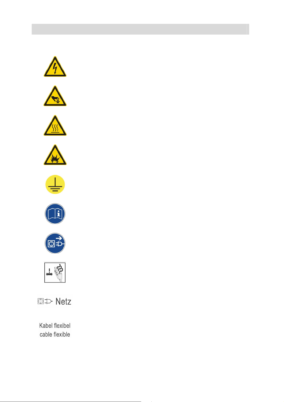
Warning of dangerous electric voltage
Warning of rotating components
Warning of hot surfaces
Warning of deflagration
PH-01
grounding
Observe operating or installation instructions
Separate electric system from the mains
Pull angle plug aside
power Supply
Do not use rigid cable for installations
10
Page 11
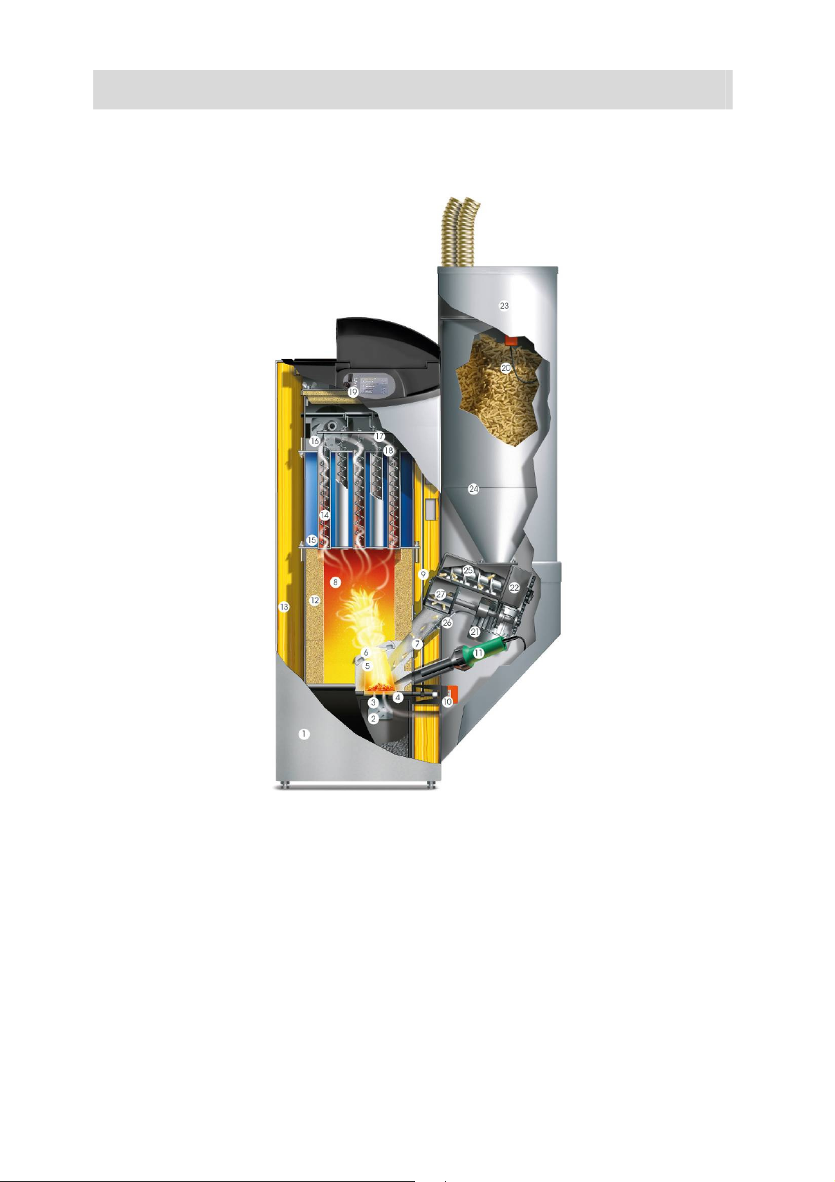
3 SYSTEM COMPONENTS
Flex / Box
BS-01
1. Ash box door
2. Cleaning grate
3. Primary air
4. Self- cleaning grate
5. Secondary air
6. Swirl plate
7. Burn- bacl
8. Expansion zone
9. Automatic heat exchanger cleaning
10. Grate cleaner motor
11. Ignition fan
12. Ceramic insulation
13. Overall insulation
14. Helix baffels
15. Tube- type heat exchanger
16. Flue draught fan
17. Flue gas sensor
18. Lambdasond
19. Control unit
20. Sensor-filler level
21. Motor
22. Drive gear
23. suction fan
24. storing box
25. Pellet spiral
26. Sensor-burning monitioring
27. rotary valve
11
Page 12
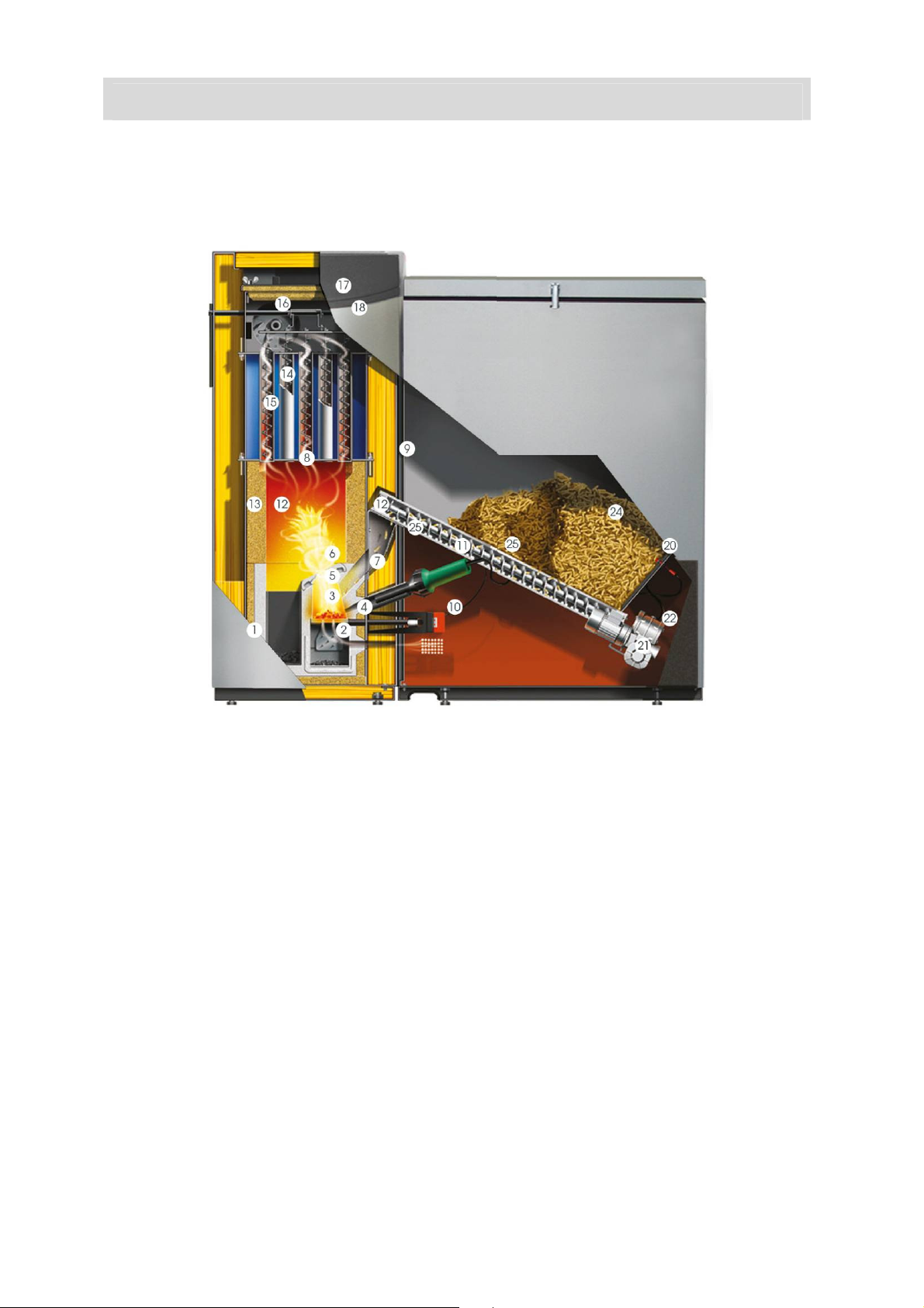
Weekbox
BS-01
1. Ash box door
2. Cleaning grate
3. Primary air
4. Self cleaning grate
5. Secondary air
6. Swirl plate
7. Burn- back inhibiting fuel chute
8. Expansion zone
9. Warmchangercleaning
10. Grate cleaner motor
11. Ignition fan
12. Ceramic insulation
13. Overall insulation
14. Helixx baffles
15. tube type exchanger
16. Flue draught fan
17. Flue gas sensor
18. Lambdasond
19. Control unit (controller)
20. Sensor-for fill- level indicator
21. Motor
22. Gear
23. vacuum fan
24. Fuel hopper
25. pellet spiral
12
Page 13

4 SAFETY SYSTEMS
Safety level 1
Safety level 2
Safety level 3
BS-01
To prevent the boiler overheating, the controller reduces the
heat output in certain situations. If the boiler still threatens to
overheat, the controller responds according to a set of defined
safety levels.
15°C above specified temperature
The drive motor Stops the fuel feed system and the flue
draught fan shuts down.
Boiler temperature above 85°C
All heating pumps and the cylinder charging pump are
switched on to carry heat away from the boiler
Boiler temperature above 100°C
The STL (safety temperature limiter) trips and switches all
boiler control functions off while the heating circulation pumps
continue to run. The system remains switched off even if the
boiler temperature drops back below 90 °C. The system must
not be started up again until any faults have been rectified and
the boiler has been checked.
Power failure The controller, the flue draught fan and all circulation pumps
switch of due of electricity if there is a power cut. The glowing
fuel bed on the grate continues burn with the natural draught of
the flue. As this operating mode is not ideal, a larger amount of
ash collechts on the grate as well. As soon as the electricity
supply is restored, the controller takes control of the heating
system again.
Opening the ash box
• the auger motor Stopps feeding in fuel;
• the suctionblower goes to 100 % extraction speed;
• After the firebox door is closed, normal operation is
resumed or re- ignition initiated
13
Page 14
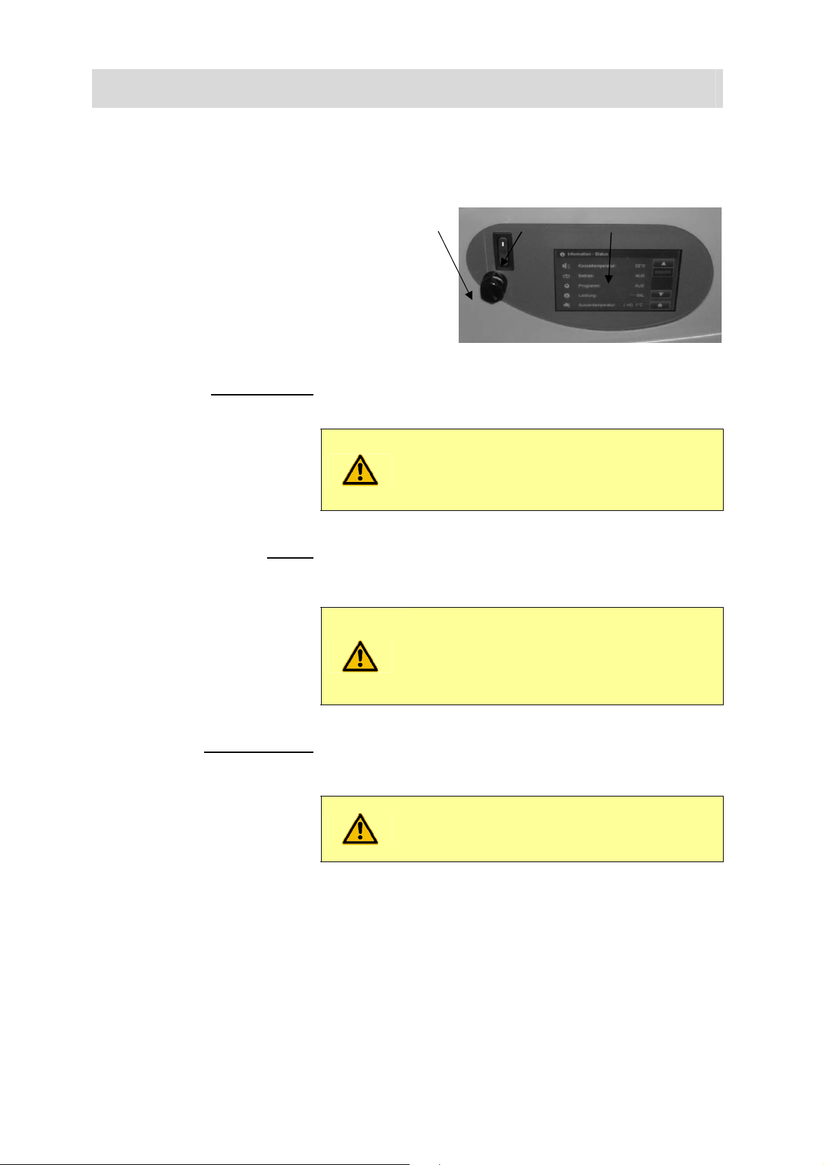
5 CONTROL PANEL DESCRIPTION
The appliance has a large touch- screen control panel with a
meu- based interface. All setting and query options are shown
on the display. All setting could be entered by pressing the
“buttons” on the touch screen. Any system messages are
displayed on the screen.
Power switch (1) Normally remains permanently switched on. The power switch
may only be switched off when the system is not in operation.
The system must be disconnected from the
BS-01
2 1 3
mains by unplugging the power lead when
carrying out repairs or servicing work
BS-01
Excessive temperature trips the safety temperature limiter
STL (2)
(STL) located under the cap (2) appliance operation is
suspended; if the STL has tripped, identify and eliminate the
cause and then press in the STL (button) with a thin object.
The system must not be started up again until
any faults have been rectified and the boiler
has been checked. If necessary, a heating
engineer must be called in.
Pressing lightly with your fingertip on the relevant buttons on
Touch-Display (3)
the display opens the various program levels, menus and
submenus. All settings are made directly on the touch-screen
display.
Never use sharp objects such as ball-point
pens or the like to operate the touch screen
14
Page 15
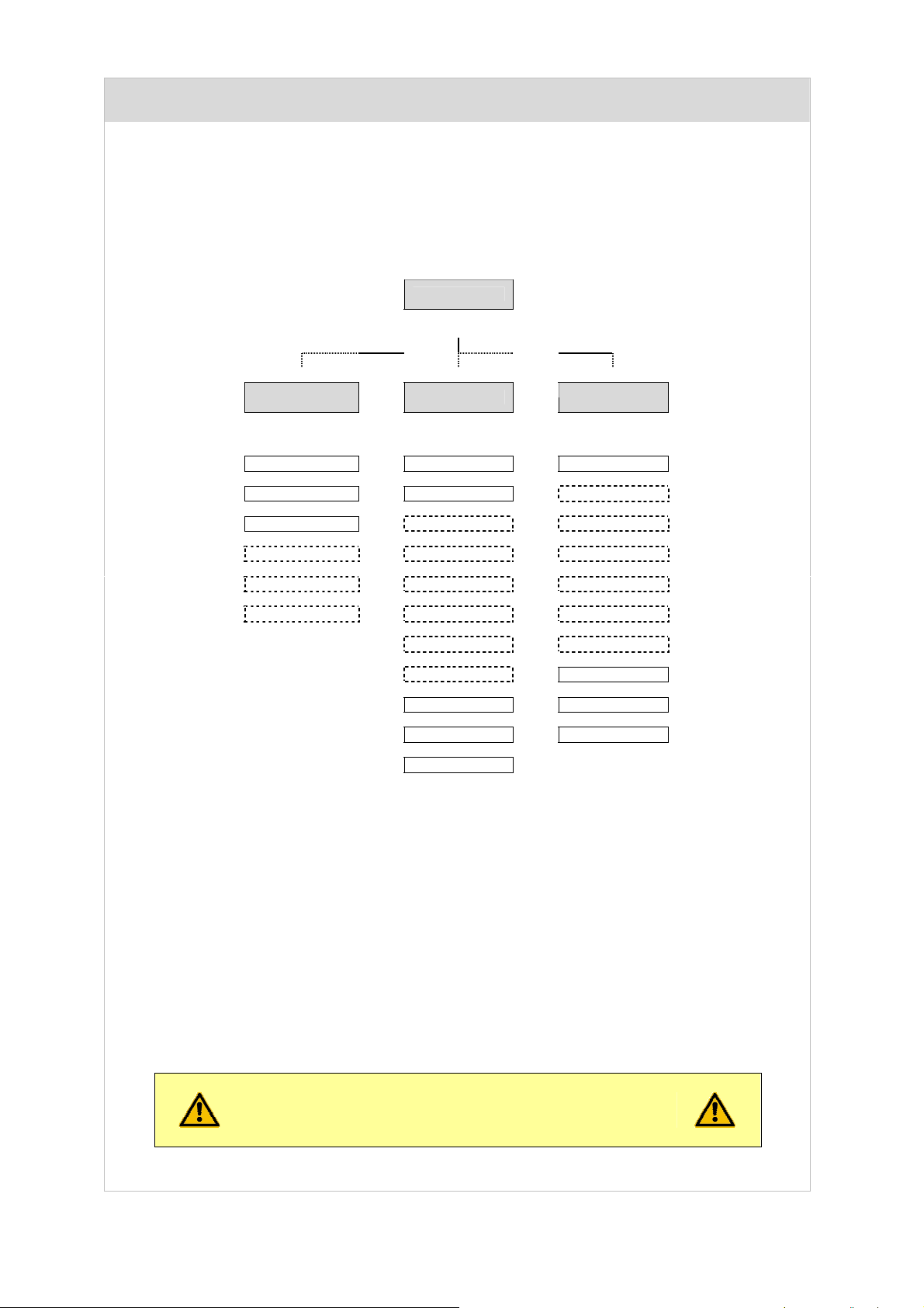
6 OVERVIEW OF MENU LEVELS
Info level
▼ ▼ ▼
INFO-Error
INFO-Status
INFO-Boiler
INFO-Controller 0-2
INFO-Buffer Tank HP0
INFO-Buffer Tank 0-2
Prog. selection
MANUAL OPERATE
House level
Boiler release
OFF
NORMAL
DHW
HEAT
REDUCE
REDUCE TO…
BOOST DHW
Grate cleaning
exhaust. value
PH-01
Customer level
Customer menu
Heating Circ. 0-8
DHW
DHW extra 0-2
Menu HP0
trunk blink 0-2
Blr. cascade
Detail display.
date-time
Service level
Menus shown with a dashed border only appear if
activated on the Commissioning menu.
15
Page 16

6.0 HOUSE LEVEL
About the selection buttons, you switch to the different levels.
BC-01
Info level
see Chapter 6.1
see Chapter 6.2
Customer level
Program selection
*)
*)
INFOBOX
-
Error messages, Temperatures, Scold and operational states, Buffer and
Heating circles could be requested.
**)
***)
***)
16
**) -
Programmes for boilers and heating circulations could be chosen;
-
the boilers release could be broken;
-
the attitudes for boilers, heating circulations could be changed
-
the attitudes in the service area and the parameter menu could just
changed from authorised GUNTAMATIC staff.
Page 17

6.1 PROGRAMMESELECTION
1)
1)
1)
1)
1)
1)
Boiler´s clearance ...........................................
Programme OUT ............................................
Programme NORMAL ....................................
Programme WARMWATER ...........................
Programme HEATING ....................................
Programm LOWER.........................................
Programm LOWER TO ..................................
RELOAD WARMWATER ...............................
Programme MANUAL .....................................
gratecleaning ..................................................
emissions measurement ................................
INFOBOX
1) the selectionbuttons wehre just shown,if a heatingcirculation is actived;
on Attitude „OFF“ the boiler didn´t start
Heiatingrun turned off (mit wittgef. Regelung ist die Frostschutzfunktion aktiv)
Heizung und WW-Bereitung eingeschaltet (nach Uhrenprogramm)
heating turned off – WW- Bereitung eingeschaltet (after Watchpr. summer)
Day and Night heatingrun (Warmwater with watchprogramme)
Day and Night reduced mote (Warmwater with watchprogramme)
Absenkbetrieb bis zu einem bestimmten Zeitpunkt
Duration maximal 90 Minutes
Heatingservice on boilerstarget- or buffertargettrmperature
manual ON and OFF
Programm for Emissionsmeasure
back to HOUSELEVEL..............................
look at Chapter 6.0
PH-01
6.2 COSTUMER LEVEL
2)
2)
2)
2)
2)
2)
Customer menu .................................................................................................................
Heatingcirculatopn 0-8 ......................................................................................................
Warmwater 0-2..................................................................................................................
addition Warmwater 0-2 ....................................................................................................
Loadingpump 0-2...............................................................................................................
bufferpump 0-2 ..................................................................................................................
feederpump 0-2 .................................................................................................................
buffer- / Z-pump HP0.........................................................................................................
boilerscascade...................................................................................................................
Detailscreen .........................................................................
Date-time ..................................................................................................
Servicelevel .......................................................................................................................
INFOBOX
2) the selectionbuttons could just actived in connection with a heatingcircle;
attitudes, condition and measurement of construction will be shown!
Date and time from the machine could be attituded
back to house level ....................................
PH-01
look at Chapter 6.2.1
look at Chapter 6.2.2
look at Chapter 6.2.3
look at Chapter 6.2.3
look at Chapter 6.2.4
look at Chapter 6.2.4
look at Chapter 6.2.4
look at Chapter 6.2.5
look at Chapter 6.2.6
look at Chapter 6.2.7
look at chapter 6.0
17
Page 18

6.2.1 COSTUMERMENU
3)
Ash empty ......................................
Ashwarning .....................................
boiler´s target ..................................
Clearance HKR 0-2 ........................
m³ set Counter to 0 ........................
Attitude m³ Counter ........................
fill the spiral .....................................
fill the suction construction .............
Feed ...............................................
Mode ...............................................
Language ........................................
boiler´s off time ...............................
INFOBOX
3) ECO-ideal ........... Attitude Savemote (Factoryattitude);
high Power......... Attitude needs more cleaning (attitude just shortly);
much dust.......... Attitude for low quality Pellets with am high Dustpart;
viel Schlacke...... Einstellung bei starker Schlackebildung im Brennraum;
after cleaning the Ash the choose the Menüpoint and confirm with „YES“ and „OK“
hours to the new „Ashewarning“ after confirmation of the Function „Ash emptiing“
Attitude possible, when programme houselevel is active.
influenced the state of running of trunkblinkfunction
turns the m³ Counter to 0
influenced the numberspeed (high Value = quicker count)
manueal refill of Stokerchannel (stopps automatically)
manual refilling of storing tank (is stopping automatically)
no refilling with storingtank while the OFF time (excepted forcefilling)
Attittude of burningmode
attiude of countries specific language
attitude possible, wenn HP0 auf Kein, Z-Pumpe oder Pumpe eingestellt ist
back to the Costumerlevel.........................
see Chapter 6.2
BS-01
6.2.2 HEATINGCIRCULATION
4)
5)
6)
7)
8)
9)
10)
Running with Pump ........................
Watchprogramme ...........................
Targettemperature Day ..................
Targettemperaturer Night ...............
Roominfluence ................................
Heatingcurve...................................
Night off OT.....................................
Turn OFF OT ..................................
INFOBOX
4) AUTO .................. the trunkblinkfunction will be turned automatically ON/OFF;
OFF..................... the trunkblinkfunction is turned off
DURATION ......... the trunkblinkfunction is always released; (no mixer control)
5) the rule on target temperature is just active, if the temperature´s value isntß exceeded;
6) the rule on target temperature´s value is just active, if the outsidetemperature´s value isn´t exceeded to the parameter “Night Out
OT”
7) 0 % – 100%.......... with an high outiside temperature „plus degree“ a low room temperatzre will turned on if the whised
T1C° - T3°C ........ the rooms target temperature the heatingcirculation pump will turned off;
8) a higher attituded value of the same outside temperature;
9) while the reduced mote will be fell below, you have to pot the heatingcirculation ON;
Attention: There is no Antifreezefunction up to the reached attitudet temperature!
10) if the heating period will be fell below the heatingcirculation turns off;
roomtemperature is reached;
influenced the state of condition of heatingcirculation
Attitude of heating- and Absenkphasen
for Rule on targettemperature is a roommachine necacerry
zur Regelung auf Solltemperatur ist ein Raumgerät erforderlich
0% - 100% beeinflusst die Vorlauftemperatur / T1°C - T3°C beeinflusst die Heizkreispumpe
beeinflusst die Vorlauftemperatur – (high attitudevalue = high flow temperature)
influenced the heatingcirculation while the flow temperature
influenced the heatingcirculation while the heating measurement is running
back to the costumer level.........................
look at Chapter 6.2
BS-01
18
Page 19

6.2.3 WARMWATER or ADITIONAL WARMWATER
11)
12)
Running Pump ................................
Watchprogramme WW ...................
Watchprogramme. WW Sommer ...
WW Targettemperature..................
WW priority .....................................
WW reload ......................................
influenced the runningstate of warmwater circulation
influenced the warmwater loadingtime with Programme NORMAL
influenced the warmwater loadingtimes while Programme WARMWATER
influenced the watertargettemperature
influenced the heatingcirculations while the warmwaterloading
onced warmwaterloading possible outside the programmed loadingtimes
back to the costumerlevel..........................
INFOBOX
11) AUTO.................. the trunkblinkfunction will be turned automatically ON/OFF;
OFF..................... the trunkblinkfunction is turned off
DURATION ......... the trunkblinkfunction is always released; (no mixer control)
12) NO....................... the heatingcirculations stay running;
YES..................... the heatingcirculations will be shutted off
PH-01
look at Chapter 6.2
6.2.4 BOX, BUFFER or SCREWPUMP
13)
14)
15)
Running Pump ................................
Loadingprogramme ........................
Watchprogramme ...........................
Buffer target ....................................
Buffer min........................................
influenced the runningstate of trunkblink.
influenced the warmwater loadingtime of buffer
influenced the trunkblinks release
influenced the buffertargettemperature
influenced the bufferminimumtemperature
INFOBOX
13) AUTO.................. the trunkblinkfunction will be turned automatically ON/OFF;
OFF..................... the trunkblinkfunction is turned off
DURATION ......... the trunkblinkfunction is always released;
14) Full...................... the trunkblinkbuffer will be so long loaded, till the buffertargettemperature is reached on the buffersensor „ABOVE
Partly .................. the trunkblinkbuffer will be loaded so long, till the buffertargettemperature is reached on the buffersensor „ABOVE
15) if the attituted temperature „buffer min“ will fell below, the buffer will be loaded automatically to the „buffer target“ temperature;
(T3)“ – and the temperaturedifference to the buffersensor „Below T 2“ is just 10 ° degrees;
(T3)“;
back to the costumer level.........................
PH-01
look at chapter 6.2
19
Page 20

6.2.5 EXIT HP0
16)
17)
18)
Running Pump ................................
Boiler´s target..................................
Loadingprogramme ........................
Watchprogramme ...........................
Buffer Target ...................................
Buffer min........................................
INFOBOX
16) AUTO.................. the trunkblinkfunction will be turned automatically ON/OFF;
17) Full...................... the trunkblinkbuffer will be so long loaded, till the buffertargettemperature is reached on the buffersensor
18) if the attituded „buffer min“ temperature will fell below, the buffer will loaded automatically loaded to the „buffer targe t“
PUFFERSPEICHER / Z-PUMPE / PUMPE
influenced the runningstate of trunkblink.
influenced the buffertarget temperature (manual)
influenced the state of charge from the buffers
influences the boiler´s free release
influenced the buffertargettemperature
influenced the bufferminimumtemperature
back to the COSTUMER LEVEL...............
see chapter 6.2
OFF..................... the trunkblinkfunction is turned off
DURATION ......... the trunkblinkfunction is always released;
Partly .................. the trunkblinkbuffer will be loaded so long, till the buffertargettemperature is reached on the buffersensor
temperature
„ABOVE (T3)“ – and the temperaturedifference to the buffersensor „Below T 2“ is just 10 ° degrees;
„ABOVE (T3)“;
BS-01
20
Page 21

6.2.6 SERVICELEVEL
19)
19)
19)
19)
19)
19)
Resetdata...........................................................................................................................
Error list.....................................................................................................................
Test program................................................................................
Begin Service.....................................................................................................................
Parameter HK 0-8 ...................................................................
Parameter Warmwater 0-2................................................................................................
Parameter adition WW 0-2.......................................................................
Parameter HP0 .......................................................................
Parameter FL 0-2................................................................................................
Parameter RLM ..............................................................................................
Constructionattitude...........................................................................................................
Parametermenu ..............................................................
INFOBOX
19) the numbers of the shown parameters are dependent from the system configuration;
Servicecooperator
All systemcomponents could be undergo to an functioning test!
(heatingcirculation / Estrichheizen)
(Adition warmwater)
(Z-Pumpe / Pufferpumpe / Pumpe)
(trunk blinkl)
(backrun mixer)
entrance and changes just allowed with backspeech from GUNTAMATIC!
back to the COSTUMERLEVEL................
PH-01
look Chapter 6.2.7.1
All errors are saved with date and time!
look Chapter 6.2.7.2
look Chapter 6.2.7.3
look Chapter 6.2.7.4
look Chapter 6.2.7.4
look Chapter 6.2.7.5
look Chapter 6.2.7.6
look Chapter 6.2.7.7
look Chapter 6.2.7.8
look at Chapter 6.2
6.2.6.1 RESETDATA
load Costumerparameter................
save Costumerparameter
load Costumerparameter!...............
operatinghours reset.......................
Servicetime reset ............................
Steerege reset ................................
Lambdakalib. reset .........................
BS-01
saved costumerdatas could be imported new, if necaserry
just new or changed parameter were loaded with a new software
reset factorytimer to 0
reset factory hour timer to 0
Attention: the factory setting will be loaded!
reset it after every lambdasondchange
back to the SERVICELEVEL.....................
look at chapter 6.2.3
21
Page 22

6.2.6.2 BEGINNING SERVICE
2)
21)
22)
23)
24)
25)
26)
27)
Construction.......................................................................
Type ...................................................................................
Feed ...................................................................................
Ashfeed ..............................................................................
HKR 0-2 available................................
● WW availabe 0-2 ..............................
● Running HK 0-8 ..................................
○ flow temperature 0-8 max....................................
○ Heatingcurve 0-8 .................................................
○ Room machine HK0-8 .........................................
● Run trunk blink 0-2 .....................................................
● Spring.......................................
● adition 0-2 ..................................................................
Running HP0......................................................................
Sensor HP0........................................................................
Backrunmixer .....................................................................
A1 Suctionlength................................................................
First filling.........................................................
Spiral´s filling......................................................................
save costumer parameter..................................................
(heatingcirculationruler)
(warmwatermemory)
(heatingcirculation)
(on trunkblinkfunction LAP)
(don´t breake)
back to the SERVICELEVEL
Selection: Biocom
Selection: 30 / 40 / 50 / 75 / 100 kW
Selection: Flex
Selection: Yes / No
Selection: No / CAN-Bus / SY-Bus / Yes
Selection: Yes/ No
Selection: No/ pump/ mixer
Selection: 10°C – 90°C
Selection: 0,1 – 3,5
Selection: No / RFF / RS-Voll / RS-HK / RS-HKR
Selection: No / ZUP / PUP / LAP / ERW
Selection: buffer 0 / buffer 1 / buffer 2 / buffer HP0
Selection: No / WWP / Extern
Selection: Z-Pum p / Bufferpump / Pump
Selection: Kessel / HKR0 / HKR1 / HKR2
Selection: Yes / No
Selection: 5 m / 10 m / 15 m / 20 m / 25 m
Selection: OK / OFF
Selection: OK / OFF
Selection: Yes/ No
look at Chapter 6.2.6
BC-01
INFOBOX
20) No ....................... there is no heatingcirculation associated;
SY-Bus ............... the attituded is correct, when the boilerintern rule will be used as heatingruler 0;
CAN-Bus ............ the attitude is right, when the wall mounted construction is used as heatingcirculation;
Yes...................... the standardattitude fort he underfloor heating is right, when the wall mounted construction is used as
21) 0,5 – 0,7.............. the standardattitude for underfloor;
1,2 – 1,4 .............. the standardattitude for the heater;
22) None................... the heatingcirculation isn´t dedicated to a room machine;
RFF ..................... the heatingcirculation isn´t dedicated to an analouge machine;
RS-Voll ............... to the heatingcirculation there is an digital room construction with attituded possibilities for all heating circulations;
RS-HK................. to the heatingcirculation there is an digital room consturikton with attitudepossibillites for this heatingcirculationruler;
RS-HKR .............. to the heatingcirculation there is an digital room construction with attitudepossibilities fort the whole
23) ZUP, PUP, LAP ........... for the correct attitude have a look at the scheme;
ERW............................. the attitude is correct, if a second heatingcirculationruler is attributed to an existing trunk blink;
24) this attitudion determinates from that buffermemory the Energy will get from the trunk blink;
25) the function „adition“ could be actived on the heatingcirculationrulerm, if the H (0, 3 or 6) ehere in service without a mixer;
WWP................... an aditional warmwatermemory could go in service;
Extern................. an external burner could be requested with cascadefunctions;
26) Z-Pump........................ attitude for constructions without buffermemory with heatingregulation;
Pufferpump................. attitude for construction with buffermemory
Pump ........................... attitude for construction without buffermemory and withour heatingcirculationruler;
27) This attituded determinates, on that ruler sensor of buffer HP0 is connected;
heatingcirculationruler 1 or 2;
heatingcirculationtuler;
22
Page 23

6.2.6.3 PARAMETER HK 0-8
In Service HK .....................................................................
Roomconstruction HK........................................................
Mixerruntime ......................................................................
Flow temperature min ........................................................
Flow temperature max.......................................................
boiler cant ..........................................................................
Heatingcirculationpump Freigabe Temperatur .................
Paralleldisplacement heatingcurve ...................................
Floorheating .......................................................................
● advance increase .......................
● advance increase to ...................................................
● Floor advance min. .....................................................
● Floor advance max. ....................................................
● Floor halftime ...........................................
● Start floorprogramme .................................................
HEATINGCIRCULATION / FLOORHEATING
Selection: None/ Pump / Mixer
Selection: None / RFF / RS-Voll / RS-HK / RS-HKR
Selection: 10 – 300 seconds
Selection: 10°C – 90°C
Selection: 10°C – 90°C
Selection: 0°C – 20°C
Selection: 20°C – 100°C
Selection: -10°C – 30°C
Selection: Yes/ No
(daily at programmestart)
(Runtime max.)
back to the servicelevel .............................
Selection: 0°C – 10°C
Selection: 1 – 5 Days
Selection: 10°C – 30°C
Selection: 25°C – 60°C
Selection: 0 – 20 Days
Selection: Yes/ No
look at Chapter 6.2.7
BS-01
The attitude of floorparameter has to occur with the
floormaker!
The compliance of specific temperatures is not in the slipped service
possible, just by the automatic mixes. The compliance couldn´t
guaranted by 100% because of security escapements and special
boiler features could in exception clear temperaturedifferences. If there
are some problems cause of builted damages, you have to make the
floor heater by hand.
6.2.6.4 PARAMETER WARMWATER 0-2
Warmwater / Adition WW availible....................................
Warmwaterer Hysterese....................................................
Warmwaterpump Clearance .............................................
boilerscant..........................................................................
back to the Servicelevel ............................
or ADITION
Selection: Yes / No
Selection: 1°C – 30°C
Selection: 20°C – 90°C
Selection: 0°C – 20°C
WW 0-2
PH-01
look at Chapter 6.2.7
23
Page 24

6.2.6.5 PARAMETER HP0
in Service HP0 ..............................
Clearence HP0 ............................................
Buffer above Loading ON..............
Buffer above Loading OFF.................
Buffer below Loading OFF ...............
Delta T trunkblink......................................
Difference boiler-buffer above...........................................
Sensor HP0...................................
aditional sensor..............................................
BUFFERPUMP / Z-PUMP / PUMP
6.2.6.6 PARAMETER FL 0-2
Service trunkblink ............................
Clearance trunkblink...................................
buffer above Loading ON ..............
Buffer above Loading OFF.................
Buffer below Loadung OFF ..............
Source..........................................
Delta T trunkblink......................................
Differenz boiler-buffer above.............................................
(for attitude hav a look above)
(Pumpclearence)
(Unterschreitung Kesselanf.)
(Überhöhung Kesselanf.)
(Differenz Puffersoll zu T2)
(Temperaturverlust)
(buffersensor conected on →)
(5 buffersensor)
back to the Servicelevel ............................
trunk blink
(Einstellung siehe Schema)
(Unterschreitung Kesselanf.)
(Differenz Puffersoll zu T2)
(bei Fernleitungsfunktion LAP)
(Pumpenfreigabe)
(Überhöhung Kesselanf.)
(Temperaturverlust)
back to the servicelevel .............................
Selection: Z-Pum p / bufferpump / Pump
Selection: 65°C – 80°C
Selection: 0°C – 20°C
Selection: 0°C – 20°C
Selection: 0°C – -20°C
Selection: 0°C – 50°C
Selection: 0°C – 50°C
Selection: boiler/ HKR0 / HKR1 / HKR2
Selection: Yes / No
look at chapter 6.2.6
Selection: None / ZUP / PUP / LAP / ERW
Selection: 40°C / 65°C – 80°C
Selection: 0°C – 20°C
Selection: 0°C – 20°C
Selection: 0°C – -20°C
Selection: buffer 0 / buffer 1 / buffer 2 / buffer HP0
Selection: 0°C – 50°C
Selection: 0°C – 50°C
look at chapter 6.2.6
PH-01
PH-01
6.2.6.7 PARAMETER RLM
28)
29)
Service Backrunmixer........................................................
Backrunmixer Runtime ......................................................
Backrunmixer Target .........................................................
Backrunmixer Delta T ........................................................
Decelerate..........................................................................
INFOBOX
Backrunmixer
Selection: AUTO
Selection: 10 – 300 Seconds
Selection: 20°C – 65°C
Selection: 5°C – 30°C
Selection: YES
back to the servicelevel .............................
PH-01
look at chapter 6.2.7
24
28) determinates the whised spreading between boilerstemperature and boilerbacktemperature;
29) makes the boiler´s target temperature higher on the attituted way (purpose= the boilers target temperature will be quicker reached);
Page 25

6.2.6.8 SYSTEM SETTINGS
30)
31)
32)
33)
33)
34)
Construction.......................................................................
Type ...................................................................................
Feed ...................................................................................
boiler´s cleaning................................
HKR 0-2 .............................................................................
Outside sensor............................
Fuel ....................................................................................
FW availiable .....................................................................
FW kalibrieren....................................................................
FW correcturer bei Pmin ...................................................
FW correcture bei Pmax....................................................
Lambdasond ......................................................................
Lambdaheating ..................................................................
Lambdasonde kalibrieren ..................................................
Lambdasonde Korrektur.........................
Lambdasonde Kennlinie...........................
PC-Überwachung ..............................................................
GSM Rufnummer 1-3 ....................
SD-Logging ...................................
SD-Data .............................................................................
CID-Data ............................................................................
Network ......................................................
DHCP .........................................................
IP-Adress ..................................................
Alert ...................................................................................
First Filling..........................................
ID Fan ................................................................................
Gear G1 .............................................................................
Fwingtype...........................................................................
Menustructure ....................................................................
time, ABS Pump .................................................
HKP Forceon .....................................................................
Restwarme using ...............................................................
HKP Freeze TA..............................
HKP Freeze TV.............................
TÜV Function .....................................................................
(possible up to yom. 2006)
(No = 0°C Outsidetemperature)
(-10,0 mV = Sollwert)
(adaption in service)
(bei aktiviertem GSM-Modul)
(for ending – save parameter)
(VISU via Network)
(VISU via Network)
(VISU via Netzwork)
(don´t break this service))
(1x weekly)
(in Programme „OFF“ active)
( in Programme „OFF“ active )
back to the servicelevel .............................
Selection: Biostar
Selection: 12 / 15 / 23 kW
Selection: Flex / Week
Selection: OUT
Selection: Yes/ No / CAN-Bus / SY-Bus
Selection: Yes
Selection: 1 = 12 kW, 15 kW / 2 = 23 kW
Selection: Yes
Selection: 0 kOhm
Selection: 0 kOhm
Selection: 0 kOhm
Selection: NGK
Selection: AUTO
Selection: ON / OFF
Selection: Correcture maximal ± 6,0 mV
Selection: 0,0%
Selection: Terminal / DAQ / GSM-Module
Selection: insert telephonenumber
Selection: ON / OFF
Selection: overview
Selection: m anufacturer code
Selection: yes
Selection: m anual
Selection: insert free Netzwork IP-Adress
Selection: don´t deactive
Selection: OK
Selection: Tact
Selection: ABM-FGA103
Selection: D140 = 12 kW, 15 kW / D150 = 23 kW
Selection: 3.1
Selection: 60 Seconds
Selection: 85°C
Selection: 65°C
Selection: -3°C
Selection: 3°C
Selection: -
look at chapter 6.2.6
BS-01
INFOBOX
30) Terminal............. Data querying via VISU;
DAQ .................... Data querying via Onlinerecorder (only useable at factory);
GSM-Modul ........ Information and control via GSM-module;
31) all heatingcirculationpumps ON, till the temperature fall below (or the buffer memory) 85 °C
32) Pump HP0 ON till the boilertemperature fell below 65 °C;
33) unterschreitet die Außentemperatur den Parameter HKP Frost TA den eingestellten Wert, schalten alle Heizkreispumpen ein;
Parameter HKP Frost TV ist die Vorlaufsolltemperatur, wenn der Parameter HKP Frost TA aktiv ist (Frostschutzfunktion);
Achtung: Durch eine Störung am Kessel kann die Frostschutzfunktion möglicherweise versagen! → E-Heizstab vorsehen!
34) die Kesseltemperatur wird solange erhöht, bis der STB die Funktion unterbricht;
25
Page 26

7 USER SETTINGS
7.1 HEATING
press the programmeselection
ON / OFF
BS-01
BS-01
Programme
Programme
Programme
OUT ........................
NORMAL ................
WARMWATER .......
some INFO’s more for Programme selection ............................... look at chapter 6.1
back to HOUSELEVEL.............................. look at chapter 6.0
▼
Heating and Warmwater turned off
Heating and Warmwater on
just Warmwater on
26
Page 27

7.2 HEATINGPROGRAMME
how to PROGRAMME
BC-01
For every heatingcirculation there could be up to 3 ON/ OFF switching times installed. With the
function „Weekprogramming“ all days in a week could be programmed at the same time.
1) press Costumer level
2) press on the heating circulation button
3) press on the watchtime progtamme
• Programme „DAILY“
(press 1 x to the weekday)
• Programm „WEEKLY“
(press 2x on the same weekday)
▼
▼
▼
back to houselevel .................................... look at chapter 6.0
27
Page 28

7.3 ROOM TEMPERATURE
adapt heating curve
BC-01
Through changing the heating curve, the room temperature could be adapted.
Through a higher heating curve you might reach a higher room temperature.
Change the heating curve just daily and maximum in a tenth area.
1) press COSTUMERLEVEL
2) press to the heatingbend button
3) press on the heatingcurve button
80
70
60
50
40
flowtemperature °C
30
20
Outsidetemperature °C
3,5 2,53,0 2,0
▼
▼
▼
1,5
1,0
0,5
-20-15-10-505101520
back to HOUSELEVEL.............................. look at chapter 6.0
28
Page 29

7.4 WARMWATERTEMPERATURE
how to ADAPT
BC-01
Through changing the targettemperature the warmwatertemperature could be adapted..
1) press COSTUMERLEVEL
2) press on the warmwaterbutton
3) press on the targettemperature button
• „CHANGE" with or
• „SAVE“ with
▼
▼
▼
back to HOUSELEVEL.............................. look at Chapter 6.0
29
Page 30

7.5 ROOMCONTROLLER
place of construction Mount the room construction in an high of 1,5 m on the internal
adapt room temperature The knobs bringst he the oportunity to change the
how to serve
BS-01
wall. The functionalst room is there, where the occupants are
the most of time (for example: living room). In this room it´s
forbidden to furnish the thermostatvalve.
The room machine shouldn’t stand in an area
with strong influence of sun or a cockle stove.
(
open the valves completly).
roomtemperature. In the plus area (+) of the menu the
roomtemperature could be lifted up to 3 ° C. In the control
range the minus (-) temperature could be depressed up to – 3
degrees.
By turning in the plus (+) or minus (-) area in
the menu the detail.
Low:
Normal:
Heating run OFF
(if the Outsidetemperature is higher then Parameter „Night out OT“)
Heating run ON → to target temperature Night
(wenn die Außentemperatur niedriger ist als der Parameter „Nacht aus AT“)
Heating and reduced mote
(after the in the watchprogramme attiuted times)
Heating:
30
Heat→ on target temperature Day
(heat Day and Night without reduced mote)
Page 31

8 OPERATING THE HEATING SYSTEM
Initial commissioning Initial commissioning and basic adjustment of the system may
only be carried out by GUNTAMATIC engineers or authorised
GUNTAMATIC agents.
Day- to day operation Clean the heating system precisely according to the
instructions in the section Cleaning/Care. The amount of
cleaning work required is heavily dependent on the quality of
the fuel used and lower-quality fuels may necessitate more
cleaning work.
Shutting down the system The system only needs to be shut down at the end of the
heating season, if faults occur or in order to refill the fuel store.
To do so, set the system to the programme "OFF" and allow it
to cool down for approx. 120 minutes. The system can then be
shut down.
If the system is not used for extended periods (summer) also
isolate it from the power supply by disconnecting the mains
plug in order to prevent unnecessary lightning damage.
BS-01
Restarting Before starting up the system again in the autumn/winter, carry
out the annual check of the control and safety systems to
ensure they are safe and functional. We recommend that you
take out a maintenance contract so that the system operates
safely and economically.
31
Page 32

8.1 CONTROLING OF THE HEATINGCIRCULATION SYSTEM
Checking system pressure The operating pressure is normally between 1 bar and 2.5 bar.
If the system pressure is too low, malfunctions may result. If
necessary top up the water in the heating system.
Note Completely draining and refilling the system or topping
up a system filled with anti-freeze or treated water must only
be carried out by a heating engineer.
Topping up the heating system water
• The heating system water must be cold when topping
up → make sure the heating system water temperature is
below 40°C.
• Add water slowly until the required system pressure is
indicated on the system pressure gauge.
• Bleed the heating system.
• Check the system pressure again and add more water if
necessary.
Expansion vessel
Check the air pressure in the expansion tank (circa 1,5 bar)
If necessary call a plumber!
BS-01
Temperature-relief valve
Check the security functions to the right functions
If necessary call a plumber!
Heatungroomlifting Control the air supply of free passage!
If necessary call a plumber!
32
Page 33

................................
........
.............................
............
................................
................................
........
8.2 FUEL/ QUALITY
Properties Calorific value
BC-01
To achieve a smooth heating of the furnace, the quality of
the fuel has to be right. Only with high-quality wood chips
should help to ensure a reliable and trouble-free operation
of the plant. The price should be evaluated always behind
the quality requirements and it is therefore strongly advised
to use only good quality.
Important quality criteria:
• solid;
• smooth surface;
• minimal small particle;
• minimal ash decay;
• high smelting point;
ca. 4,9 kWh / kg
Bulk weight ................................
Pellet size (length)
Diameter ................................
Water content
Fusion point
Ash content ................................
ca. 650 kg / m³
5 – 30 mm
5 – 6 mm
8 – 10 %
ca. 1200°C
< 0,5 %
Quality classes
use just Pellets with EN plus Quality class A1/A2!
The storing has to occour in an dry
condition!
If the pellets are in Contact with water or
moisture they swell and disintegrate!
33
Page 34

8.3 FILL THE STOREROOM
Firstfilling/ Refilling Before first fillimng and after every complete emptying of fuil
dumping height Pellets ....................................... max. 2,5 m
The fuel store can´t be filled when the
heater is in service!
Minimum 1 hour before filling, the construction
should be turned off!
You have to empty the feed spiral
You have to suct bigger dust quantity!
the storeroom couldn´t filled completly. The discharge screw
should be filled prior to complete filling of the fuel storage over
the entire screw length about 10 cm high with pellets.
Thereafter, the fuel storage can be filled up to the maximum fill
height.
minimum all 3 years!
BS-01
Emergency filling If the automatically refilling of pellets isn´t able to run, the store
room could be “emergency refilled”:
Before you try to eliminate the error follow the description as
you can see in the chapter „Rectifying faults“ or „Replacing
fuse“.
approach:
Put he construction to „programme out“and wait till it went to
„run out“. Putt he power switch to „0“. Screw the store tunk in
above direct and screw it and fill it with bagstuff.
After that, you have to close the dished cover. The shown
allertmessage should be receipted. After that you have to
attend the at least used heatingprogramme
Open the hooper The Machine recognices this and turns the
Hooper
hackchipsspiral off. Turn the ID Fan to the full drive. The
container could be filled up to the seal border. Close the
Container lid and lock it tightly. The Service will be leaded out
automatically. Once a year the Operation will be completed
emptied and the dust sediments should be suct completely.
34
Page 35

8.4 EMPTYING THE ASH
emptying the ash Put he construction to „Programme out“and let it cool down
Glowing embers can cause fires!
Only remove the ash from the boiler or store it
Touching of hot parts could lead to skin injury!
Let the boiler cool down minimum a half an hour
Depending on the quality and quantity of uel the ash container
must be emptied often. With inferior fuel quality is shortened by
the higher proportion of dust in the fuel, the drain interval. The
ash in concentrated form. In case of high quality used fuel you
can use the ash as mineral fertilizer.
minimum a half an hour. Then you have to extract and clean
the ashtank.
in non-combustible containers.
before cleaning the ash!
PH-01
Attention: The Ashton could be hot!
Control the seal of ashtank on his correct condition. Then
insert both ashtanks and close it.
Attitude the construction to the at least attituded
heatingprogramme.
Resetting the ash warning
If the ash warning appears on the display, it has to be reset on
the "User" menu. To do so, go to the "User" menu and select
the option "Ash emptied", change the setting to "YES" and
press the "OK" button to confirm. The ash warning has now
been reset to the maximum number of hours before it is next
triggered. The time until the ash warning is issued is preset
and can be adjusted to suit the fuel being used by selecting
"Ash Warning" on the User menu on the User Level.
35
Page 36

9 CLEANING/ CARE
boiler The sophisticated cleaning system on a GUNTAMATIC heating
Attention: Danger of injury!
For safety reasons you must only carry out
servicing and cleaning when the heating
system is switched off and disconnected
from the mains, and has cooled down
Attention: Danger of live!
Servicing work inside the fuel storeroom must
only be carried out under the supervision of a
second person, who must be outside the
storeroom.
system means that regular cleaning work is substantially
reduced. All that is required is regular emptying of the ash.
The flue must be regularly swept. At the same time, the flue
connecting pipe, the flue gas box and the boiler heat
exchanger should be cleared of fly-ash.
PH-01
Depending on the load on the heating system, complete
cleaning – for which the precise procedure is described in the
section "Complete cleaning" – may be required twice a year
but should be carried out at least once a year.
Depending on efficiency, and on ash production you have to
lead interim and general cleaning, this Stepps are descriped
here.
If the heating system is subject to exceptionally high loads,
more extensive cleaning may be required.
Cover panel If there are any Contamination on the cover panel parts and
the control elements, you have to eliminate them with a wet
rag. For wetting you have to use just solvent free, mild cleaning
supplies. Don´t use any cleaning supplies like alcohol,
cleaner´s solvent or diluter, cause these cleaning methods
could be aggressive and could attack the construction´s
surface.
fuel store The fuelstoreroom and the auger feed´s spiral has to be
emptied minimum all 3 years completely (if necaceserry you
have to exhaust it), to suspend any Errors on the Feedsystem
through sediments.
36
Page 37

9.1 INTERIM CLEANING
INFO Interim cleaning must be carried out at intervals of between 2
1
2
Attention Danger of injury!
For safety reasons you must only carry out
servicing and cleaning when the heating system is
switched off and disconnected from the mains, and
week and 3 months , but minimum every half an year.
lead the following Steps in the numbered order:
1) Set the system to the programme "OFF" and allow it to
cool down for at least 1 hours.
2) Open the cover door (1), take of the ash box (2) and
empty it.
Fire danger thoruh rest ember!
has cooled down.
BS-01
3
3
5
4
3) Peel the bouncing plate with the burningchamber (3)
with a poker stick. Insert the poker stick the left ashbox
opening (4).
4) On the User menu, start the function "Clean grate"
(see Section) and allow the stepped grate (5) to clean
itself for a few minutes.
5) The deposite on the grate surface (5) and in the bore
6) Empty the rest ember from the ashbox (6) putt he ash in
7) Attitudes in the costumermenu:
Risk of injury from moving parts!
have to be scratched with a cleaning construction.
the ashroom (6) and close it tight.
Put the parameter „emptying the ash“ to „YES“
and confirm with „OK“
6
6
37
Page 38

9.2 GENERAL CLEANING
7
8
Attention Danger of injury!
For safety reasons you must only carry out
You have to make the generalcleaning twice in one year. The
minimum cleaning is anual. For that you have to lead the
points 1-7 for intermediated cleaning:
lead the following Steps in the numbered order:
1) Open the smokegasbox (7) and pull the cover angel
(8) in above direction. Suct the ash with an ash suction to the
ID Fan (10) between the warmexchangerpipe (9) and the
smokegas.
Fire danger through rest ember!
2) Controll the lambdasond (12) to an tight hub, if
necaserry built it out and clean it with an soft brush.
don´t clean the Lambdasond with highairpressure!
servicing and cleaning when the heating
system is switched off and disconnected
from the mains, and has cooled down.
BS-01
10
12
13
9
11
3) Take off the foto cell (13) and clean it with an soft
cloth. Open the revision lid (14) and check if on the switch
surface are any sediments. If necessary clean it with an
chamber cleaner.
4) Activate the programme „grate cleaning“ and let the
Tipping grate deactivated. At opened tipping grate (5) control
the burning chamber, cotroll and if necessary clean it.
Risk of injury from moving parts!
5) Close the tipping grate again (5) and check if the
chamber is able to close (16).
6) Remove the restember left and right out of the
ashroom (17) with an poking stick. Then out the ashbox inside
and close it.
7) Mount the rebuilted boilerparts carefully again, and
check the cleaningopenings on tightness
8) Attitudes in the Costumermenu:
Took the parameter „ash emptied“ to „YES“ and
confirm with „OK“.
16
14
15
17 17
38
Page 39

10 INFORMATION MESSAGES/ FAULT CODES
Category
F01 Note
F02 Fault
F03 Fault
F04 Fault
F05 Fault
F06 Fault
F07 Fault
F08 Note
F09 Note
F12 Fault
F16 Fault
F19 Note
F21 Fault
F22 Note
F23
Note
Fault
Input TKS1 open longer than "t safe"
smokegassensor > in "Ruler" > after
time Param. "X25" > RGT is + ½ KT is
smaller Param. "RGTk" bt.30-100%
No response from Hall-effect sensor G1
Param. "O2 sensor" or adjusted setting
above the limits of param. "mV top" or
Length of an oxygen sensor pause
Fill level not reached within the time
Ash box wasn´t emptied in the attituted
activator Message Quit. cause
Firebox door or ash box
(door switch)
Clippinggrate could go in 200
seconds not in position
„CO2 after“ will be go under in
20 Minutes when starting
Boiler´s temperature to high!
Fotosensor via time
„parameter“ Tübf
while ignition the Co² value and/
or FW value wouldn´t reached
Para: FW Ignit.
Para: TZ1-TZ4
the filler´s level in the fillingroom
will be not go under
spiralsrunningtime „LZ G1“ min
Fillerlevel in the storeroom is
undercutted
within time "t safe"
STL tripped
"mV btm"
longer than "t stop"
"Outfeed max" .
cleaning time.
Filler levels doesn´t react
above limits. Test oxygen
open
(F01)
Clipgrate could´nt reach
gratecontroll
(F02)
Lambdasondenvalue in
the Start to high
Lambdasondtest!
(F03)
Boiler temperature too
high. Check flue draught
and boiler sensor.
(F04)
burningfail
fuel, grate, sir slider
Controll
(F05)
burning chamber, rust,
drophole, hackchips
controll!
(F06)
Ignition not possible.
Check fuel and grate
(F07)
(F08)
Fillerlevel undercuttet!
refill hackchios!
(F09)
Drive motor G1 jammed
(F12)
Warning STL hightemperature limiter
tripped
(F16)
lambda sond readings
sensor
(F19)
Oxygen sensor pause
timeout. Test oxygen
sensor.
(F21)
Fill level not reached.
Check vacuum system
(F22)
Empty ash box
(F23)
Automatic
Reset
button
Reset
button
Reset
button
Reset
button .
Reset
button
Reset
button .
None
Automatic
Reset
button .
Press STL,
Reset
button .
Reset
button
Reset
button
Reset
button
Reset
button .
BS-01
Door switch defective,
connector faulty, door or ash
box open
ashroom filled, servermotor
faultly, connection faultly
Lambdasond faulty or wrong
pumpfunction not ok, boiler´s
clogged, vacuum system not
attituted
boiler´s function not ok,
feeler faulty
no Fuel;
wrong airattitude;
flue draught wrong;
smokegassensor faulty
no Fuel;
Ignition faultly;
smokegassensor not in
position
no Fuel;
Ignition faulty
Filler levels dusty or faulty
No fuel;
Fillerlevel´s sensor faulty
Fuel chute overfilled
gearmotor faulty
boilerfunctions not OK,
pumpfunctions not ok,
boiler´s target not OK,
boilers sensor faulty, check
covering STB faulty
Lambdasond dirty
Lambdasond faulty
Lambdasond faulty;
flue draught wrong;
RGT to low
No fuel, fill level sensor
defective, vacuum pipes
air-tight, vacuum unit
defective, outfeed motor
jammed
Ash box not emptied or
counter not reset after
emptying
39
Page 40

11 FAULT CLEARENCE
Fault Cause/ Function Remedy
• Power supply disconnected
Control panel cannot be switched on
Smoke escaping into boiler room
Heat output too low
Detonation
Difficult limit output
• Fuse blown
• Flue pipe leaking
• Flue draught regulator
• Flue not clear or not providing any
• Boiler very dirty
• Heating system inadequately
• Boiler priority active
• Flue draught in chimney flue too
• Detonation is only possible if the
• Flue draught is too great
• Wide demand fluctuations on the
unfavourably positioned
draught
balanced
low
firebox is overfilled.
part of heating system
components
PH-01
• Check external mains plug and/or
power supply lead between circuit
boards
• Check fuse in supply lead and on
the control panel circuit board
• Eliminate leaks
• Consult flue installer
• Check flue
• Carry out complete cleaning
• Balance heating system and
heating pumps
• W ait until boiler charging has
finished or deactivate boiler
priority
• Increase flue draught in chimney
flue if necessary
• Carry out complete cleaning or
consult engineer if necessary
• Re-adjust flue draught regulator
• Stagger heating system
component demand over time
Burning fault
Overheating/ STL tripped
Fan to noisy
Drive motor too noisy
• Lambdaprobe dirty
• Lambdaprobe loosley
• Lambdaprobe malfunction
• burningchannel dirty
• The amount of heat produced
cannot be dissipated. A heating
pump may have failed or not
started up.
• Fan is dirty
• Fan or blade loose
• Noise created by bends or rigid
connecting pipe junctions with
chimney flue
• Fan bearing defective
• Noise transmission • If necessary, place the adjustable
• Lambdaprobe cleaning
• Lambdaprobe fix
• Lambdaprobe renew
• clean the burningchannel
• Ensure heat dissipation by
switching on pumps, opening
mixer valve or turning on hot water
taps.
• The cause of the boiler
overheating must be identified (if it
happens frequently a heating
engineer should be called in).
• Check fuses on the boiler circuit
board
• Clean fan
• Eliminate cause
• Fit insulators/sleeves
• Order replacement motor
feet of the boiler on rubber pads
40
Page 41

3 mm using a medium sized
screwdriver and turn it half a turn antilockwise to release it.
12 REPLACING FUSES
2) Switch the Power switch to „0“ and unplug the mains
3) Unfasten the controller cover and remove it.
Repair work may only be carried out by
authorised technicians.!
Touching live electrical components can
cause fatal injury.
Even when the Power switch is "OFF" some
components of the system are still live.
Therefore, when carrying out repair work it is
imperative that the power supply is
disconnected by means of the "mains plug"
or a circuit breaker.
1) Set the system to the programme „OFF“ and allow it to
cool down for at least 10 minutes.
plug on the back of the boiler to fully disconnect it from
the power supply.
BS-01
4) Locate the defective fuse with the aid of the wiring
diagramme in the installation instructions and replace it.
5) Press in the fuse holder 2-
The holder and fuse will then pop out a few mm.
6) Remove the blown fuse and replace with a new one.
7) Insert the fuse holder, press it in 2-3 mm and secure it in
position by turning half a turn clockwise.
41
Page 42

13 SYSTEM LOG BOOK
System operator:
System installer:
Boiler system:
Make: .........................................................................................
Type: .........................................................................................
.........................................................................................
.........................................................................................
.........................................................................................
.........................................................................................
.........................................................................................
.........................................................................................
.........................................................................................
BS-01
Year manufactured: .........................................................................................
Heating output: .........................................................................................
The following checks are to be carried out regularly on
• Weekly visual
inspection
• Monthly checks
the automatic wood-burning boiler system by the system
operator when it is in operation:
Once a week the entire boiler system including the fuel
store is to be visually inspected. Any deficiencies identified
are to be rectified immediately.
The following monthly checks are to be carried out and, if a log
book is maintained, should be recorded in the log book:
• Flue gas passages clean (flue gas channels in boiler, flue
connecting pipe and smoke trap)
• Controller functioning properly
• Fault indication/warning system(s) functioning properly
• Combustion air and flue draught fans functioning properly
• Firebox in good order
• Portable fire extinguisher ready for use
• Correct storage of ash
• No combustibles stored in boiler room
• No accumulation of combustible deposits on roof
Fire safety closures (fire doors self-closing)
• Servicing
42
The heating system must be serviced and inspected in
accordance with the regional, local and statutory regulations of
the country of use.
Page 43

Year:
..................................
Monthly
Check
Controller
Warning system(s)
Fans
Firebox
Portable fire extinguisher
Ash storage
Items stored in boiler room
Deposits on roof
Fire safety closures
Smoke trap cleaning
Signature/initials
System operator:
.....................................................................
Jan Feb Mar Apr May Jun Jul Aug Sep Oct Nov Dec Remarks
Serviced by:
..........................................................................................
Year:
..................................
Monthly
Check
Controller
Warning system(s)
Fans
Firebox
Portable fire extinguisher
Ash storage
Items stored in boiler room
Deposits on roof
Fire safety closures
Smoke trap cleaning
Signature/initials
System operator:
.....................................................................
Jan Feb Jan Fe b J an Feb Jan Feb Jan Feb Jan Feb Remarks
Serviced by:
..........................................................................................
43
Page 44

Year:
..................................
Monthly
Check
Controller
Warning system(s)
Fans
Firebox
Portable fire extinguisher
Ash storage
Items stored in boiler room
Deposits on roof
Fire safety closures
Smoke trap cleaning
Signature/initials
System operator:
.....................................................................
Jan Feb Mar Apr May Jun Jul Aug Sep Oct Nov Dec Remarks
Serviced by:
..........................................................................................
Year:
..................................
Monthly
Check
Controller
Warning system(s)
Fans
Firebox
Portable fire extinguisher
Ash storage
Items stored in boiler room
Deposits on roof
Fire safety closures
Smoke trap cleaning
Signature/initials
System operator:
.....................................................................
Jan Feb Jan Fe b J an Feb Jan Feb Jan Feb Jan Feb Remarks
Serviced by:
..........................................................................................
44
Page 45

Year:
..................................
Monthly
Check
Controller
Warning system(s)
Fans
Firebox
Portable fire extinguisher
Ash storage
Items stored in boiler room
Deposits on roof
Fire safety closures
Smoke trap cleaning
Signature/initials
System operator:
.....................................................................
Jan Feb Mar Apr May Jun Jul Aug Sep Oct Nov Dec Remarks
Serviced by:
..........................................................................................
Year:
..................................
Monthly
Check
Controller
Warning system(s)
Fans
Firebox
Portable fire extinguisher
Ash storage
Items stored in boiler room
Deposits on roof
Fire safety closures
Smoke trap cleaning
Signature/initials
System operator:
.....................................................................
Jan Feb Jan Fe b J an Feb Jan Feb Jan Feb Jan Feb Remarks
Serviced by:
..........................................................................................
45
Page 46

Year:
..................................
Monthly
Check
Controller
Warning system(s)
Fans
Firebox
Portable fire extinguisher
Ash storage
Items stored in boiler room
Deposits on roof
Fire safety closures
Smoke trap cleaning
Signature/initials
System operator:
.....................................................................
Jan Feb Mar Apr May Jun Jul Aug Sep Oct Nov Dec Remarks
Serviced by:
..........................................................................................
Year:
..................................
Monthly
Check
Controller
Warning system(s)
Fans
Firebox
Portable fire extinguisher
Ash storage
Items stored in boiler room
Deposits on roof
Fire safety closures
Smoke trap cleaning
Signature/initials
System operator:
.....................................................................
Jan Feb Jan Fe b J an Feb Jan Feb Jan Feb Jan Feb Remarks
Serviced by:
..........................................................................................
46
If you require more system log book pages, please photocopy them
Page 47

14 PARAMETER CHANGES
BS-01
No: Parameter Standard 1. Change 2. Change 3. Change
15 ATTITUDE HEATING CIRCULATION
Heatingcirculation 0 Heatingcirculation 1 Heatingcirculation 2 Warmwater 0
BS-01
47
Page 48

GUNTAMATIC Heiztechnik GmbH
A-4722 Peuerbach / Bruck 7
Tel: 0043-(0) 7276 / 2441-0
Fax: 0043 (0) 7276 / 3031
Email: office@guntamatic.com
www.guntamatic.com
Misprints and technichal Changes reserved
48
 Loading...