

Guntamatic Biocom series, Biocom 40, Biocom 30, Biocom 100, Biocom 75 Planning And Installation Manual
...
Pellet firing englisch
BIOCOM
Planning and installation
BC-01
EN-B31-007-V12-0515
2
Information on this documentation
BS-01
Please read through this documentation carefully.
It is intended as a reference document and contains important
information on the design, safety, operation, maintenance and
care of your heating system.
We are always looking to improve our products and
documentation. Any ideas and suggestions you may have will
be gratefully received.
GUNTAMATIC Heiztechnik GmbH
Bruck 7
A-4722 PEUERBACH
Tel: 0043 (0) 7276 / 2441-0
Fax: 0043 (0) 7276 / 3031
Email: office@guntamatic.com
It is important that you pay particular attention
to the safety issues highlighted in the text by
these symbols.
The entire contents of this document are the property of
GUNTAMATIC and therefore protected by copyright.
Reproduction of any kind, communication to third parties by any
means or use for purposes other than those intended without
the written consent of the owner is prohibited.
Subject to printing errors and technical amendments.

3
Contents
BC-01
Page
1 Introduction ............................................................................4
1.1 Safety instructions 4
1.2 Gurantee and liablitiy 4
1.3 Commissioning 4
1.4 Site requrirements 4
2 Planning..................................................................................5
2.1 Fire safety 5
2.2 Minimum fire safety requirements 6
2.3 Boiler room requirements 7
2.4 Flue requirements 9
2.5 Flue draught regulator and pressure- surge compensator 10
2.6 Fuel store requirements 11
2.7 Examples for planning 13
2.8 Automatically ash System 15
2.9 Heating circuit Rules 17
3 Constructiom........................................................................19
3.1 Delivery 19
3.2 Carrying to installation site 19
3.3 Positioning and aligned the boiler 19
3.4 Plumbing connections 20
3.5 Filling and bleeding system 23
3.6 Flue connection 24
3.7 Construction holding 25
3.7.1 System FLEX 25
3.7.2 System BOX 29
4 Electrical connections .........................................................30
4.1 Heating system electrical connections 32
5 Final checks..........................................................................33
6 Standards/ Regulations .......................................................34
7 Plumbing diagrams..............................................................35
7.1 Backup Memory HP0 35
8 Technical data ......................................................................54
8.1 Biocom 30 / 40 / 50 54
8.2 Biocom 75 / 100 55
8.3 Holding System FLEX 56
8.4 Holding System BOX 56

4
1 Introduction
BS-01
1.1 Safety instructions
GUNTAMATIC heating systems represent state-of-the-art
technology and meet all applicable safety regulations. Incorrect
installation can endanger life and limb. Heating boilers are
combustion systems and are potentially dangerous if handled
incorrectly. Installation, commissioning and servicing must,
therefore, only be carried out by adequately qualified
technicians observing all regulations and the manufacturer's
instructions.
1.2 Guarantee and liability
The manufacturer's guarantee is subject to correct installation
and commissioning of the heating system. Defects and
damage caused by incorrect installation, commissioning or
operation are not covered by the guarantee. To ensure that the
system functions as intended, the manufacturer's instructions
must be followed. Furthermore, only genuine replacement
parts or parts explicitly approved by the manufacturer may be
fitted to the system.
1.3 Commissioning
Commissioning of the boiler must be carried out by an
authorised GUNTAMATIC specialist or other qualified persons.
They will check whether the system has been installed
according to the plans, adjust the system settings as required
and explain to the system operator how to use the heating
system.
1.4 Site requirements
When establishing the site requirements, it is absolutely
essential to take account of the locally applicable planning,
building and implementation regulations and the dimensional
specifications in the fitting guidelines, installation examples and
technical data. Compliance with the locally applicable
regulations and the correct implementation of the measures
required on site are solely the responsibility of the system
owner and are a requirement of the manufacturer's guarantee.
GUNTAMATIC provides no guarantee of any kind for any type
of site work. Without making any claims as to completeness or
non-applicability of official requirements, we recommend the
following specifications based on the Austrian Guidelines pr
TRVB H 118:

5
2 Planning
01
2.1 Fire safety
BS-01
The fire security instroductions are obligatory needed
on the construction place
The Compliance from counties ore states fire security
law is obligatory and stands higher then the
GUNTAMATIC fire security instruction
Austria State legislation of the federal states
Technical Directive on Preventative Fire Safety (pr TRVB H118)
Germany Standard boiler regulations (M-FeuVO)
Hessen and Saarland – in these states §16 FeuVO Hessen applies
Switzerland Fire safety regulations
(www.vkf.ch)
any other exporting countries Any fire safety office
You have to follow you specific country fire safety
rules obligatory. Your country safety rules are higher
then our GUNTAMATIC minimum rules.
If there are no specific fire security rules in your
country, you have to follow the GUNTAMATIC
introductions

6
2.2 Minimum fire safety requirements
BC-01
Boiler room Floor of concrete construction, either bare or tiled. All materials
for floor, walls and ceiling must be fire-resistant to F60/REI60
rating.
Boiler rooms door: The Boiler room’s door also might close
single handed and it has to be possible to close off the door.
Connecting doors to the fuel storeroom must also be Class
T30/EI230-C fire doors, self-closing and lockable. There must
be no direct connection to rooms in which flammable gases or
liquids are stored.
Fuel storeroom The same minimum fire safety requirements apply as for the
boiler room.
Storeroom doors/hatches: Storeroom doors/hatches must be
fire safe to Class T30/EI230-C, self-closing and lockable. There
must be a warning sign carrying the message "Do not enter
when feeder system is running" attached to the storeroom
door/hatch.
Fireproof collars: If the storeroom is not situated directly
adjacent to the boiler room, a fireproof collar must be fitted to
the extraction and air return pipes at their wall exit points from
the boiler room. If the outfeed auger goes directly into the
boiler room, it is factory fitted with a special fire safety lining.
No additional fireproof collars are required on the air pipes. If
the outfeed auger is sited entirely inside the storeroom (i.e. if
the outfeed auger does not extend out of the storeroom),
fireproof collars must similarly be fitted to the extraction and air
return pipes at their wall exit points from the storeroom.
> 50 m³
HLE - Manual fire extinguisher: If 50 m³ of fuel or more can
be stored, a manually operated fire extinguishing facility must
be installed. It must be protected against freezing and
connected to a pressurised water pipe (DN20 conduit). The
discharge point must be located directly above where the fuel
outfeed channel exits the storeroom. The fire extinguishing
facility must be identified by a sign carrying the inscription
"Fuel storeroom fire extinguisher".
Filler pipes: Filler pipes through rooms where there is a fire
risk must be provided with Class F90/REI90 cladding.

7
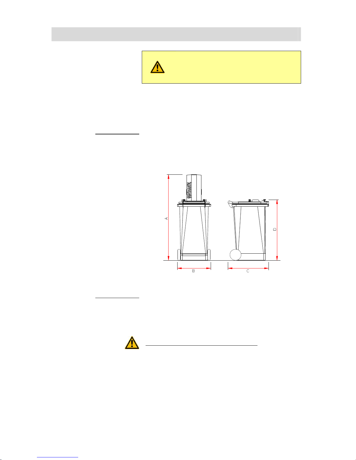
2.3 Boiler room requirements
BC-01
Minimum room height
BC 30 / 40 / 50 ideal solution
H 225 cm
1)
possible
H 210 cm
BC 75 / 100 ideal solution
H 240 cm
1)
possible
H 230 cm
1)
= minimum height on upscrewed heat exchanger
Minimum room size
BC 30 / 40/50
B 240 cm x
2)
T 230 cm
(
3)
T 240 cm)
BC 75 / 100
B 270 cm x
2)
T 230 cm
(
3)
T 240 cm)
2)
T = The room with boiler’s bodies front seeing from behind
3)
= Minimum size from the automatic ash suction system
Clear access opening
BC 30 / 40 / 50
4)
ideal
B 120 cm x H 205 cm
5)
possible
B 80 cm x H 170 cm
6)
possible
B 75 cm x H 165 cm
BC 75 / 100
4)
ideal
B 180 cm x H 210 cm
5)
possible
B 100 cm x H 190 cm
6)
possible
B 90 cm x H 180 cm
4)
= Contribution of ready mounted boiler on transportwood
5)
= Contribution without Stoker, cleaning impulse and Transportwood
6)
= Measures with aditional to Point 5) unrigged
Combustion air supply The pressure in the boiler room must not be less than 3 Pa
(0.3 mm H2O). The air vents for boiler rooms must have a
clear, net cross-sectional area of at least 200 cm² and must not
be sealable. With combustion boiler systems with a fuel heat
output upwards of 50 kW, the net, clear cross-sectional area
must be increased to at least 5 cm² per kW rated output
according to the combustion air requirement of the boiler
system. The air supply ducting must connect directly to the
outside and if the ducting passes through other rooms, it must
be jacketed to Class F90/REI90. On the outside of the building,
air vents must be covered by a protective grille with a mesh
size of > 5 mm. The supply of combustion air should, if
possible, enter at floor level in order to prevent cooling of the
boiler room.
Electrical installation The lighting and the electrical wiring in the boiler room must be
permanently installed. There must be a clearly marked
emergency off switch in an easily accessible position outside
the boiler room, close to the boiler-room door.
The line connector 230 VAC, 50 Hz, 13 A is needed.
Fire extinguisher A hand-held fire extinguisher (6kg gross weight, EN3) must be
mounted outside the boiler room near the boiler-room door.
Protection against freezing
The boiler room, pipes carrying water and any district heating
pipes must be protected against freezing.
8
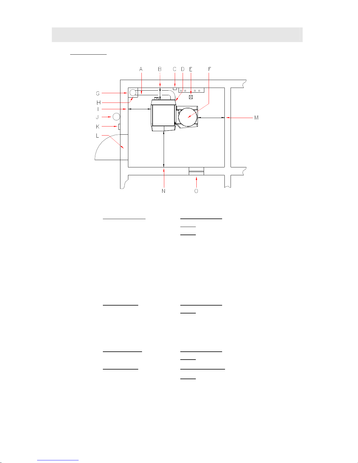
Installation site You have to plan the furnace in the near of the chimney to avoid a long
flue pipe.
A →
Integration version of Energy saving draft regulator with Ex flap and with fire tube
respect the local fire security rules- dust information possible
B →
BEHIND distance
ideal
70 cm minimum
possible
50 cm
without Ash suction system
60 cm
with Ash suction system
C →
The discharge for overheating
D →
Line Connector 230 VAC 13A
E →
Drain
F →
Sparger complex
G →
flue
wet non- sensitive chamotte-flue advised
H →
installation variant energy-saving damper with explosion damper in the flue
c
a. 50 cm under the flue – please follow the local laws
I →
LEFT distance
ideal
70 cm minimum
possible
40 cm
J →
fire extinguisher
6 kg filling weight EN3
K →
escape switcher (emergency stop)
L →
fireproof door
T30 / EI230-C lockable and self depended
M →
RIGHT distance
ideal
70 cm minimum
possible
40 cm
N →
LEFT distance
ideal
100 cm minimum
possible
80 cm
O →
Combustion air supply

9
2.4 Flue requirements
BC-01
Use heat-insulated fireclay flues that are
insensitive to damp.
The flue gas temperature can be less
than 100°C.
The system must only be connected to the flue if the flue
meets the legal requirements and the technical specifications.
The flue must be matched to the boiler output and
dimensioned in accordance with DIN 4705. In order to be able
to accurately dimension the flue, the calculations must be
based on the flue gas figures. When designing new flues, high
thermal insulation chimneys (DIN 18160 T1 heat transmission
resistance group I) or suitable fireclay flues that are
insusceptible to damp and have general building regulation
approval should be used. It is advisable to involve those
responsible for approving the flue system early on in the
planning phase.
Flue height The minimum flue height is 5 - 10 m depending on boiler
output. The flue must terminate at least 0.5 m above the
highest part of the building. In the case of flat rooves, the flue
must terminate at least 1.5 m above the surface of the roof.
Flue diameter The flue hast to adjust on the fire power. The following dates
are approximate values and could be used for planning. We
recommend calculating the flue by a professional.
BC 30 / 40 / 50
BC 75 / 100
eff. high above 6 m D = 160 mm
eff. high under 6 m D = 180 mm
eff. high above 6 m D = 200 - 220 mm
eff. high under 6 m D = off 220 mm
Flue dimensioning data Dimension the flue for rated output!
(Averaged figures with used heat exchanger)
Rated output:
Type exhaust CO2 massflow
draft
requirement
BC 30 160°C 12,5% 0,024 kg/s 15 Pascal
BC 40 170°C 13,0% 0,030 kg/s 15 Pascal
BC 50 175°C 13,0% 0,030 kg/s 15 Pascal
BC 75 190°C 13,0% 0,042 kg/s 15 Pascal
BC100 190°C 13,0% 0,055 kg/s 15 Pascal
Sub-maximum output:
Type exhaust CO2 massflow
draft
requirement
BC 30 100°C 9,5% 0,010 kg/s 2 Pascal
BC 40 105°C 10,0% 0,012 kg/s 2 Pascal
BC 50 115°C 10,0% 0,009 kg/s 2 Pascal
BC 75 120°C 10,0% 0,013 kg/s 2 Pascal
BC100 120°C 10,0% 0,017 kg/s 2 Pascal
10
2.5 Flue draught regulator and pressure-surge compensator
BS-01
Fitting an energy-saving flue draught
regulator/pressure-surge compensator
(Class RE) is absolutely imperative.
The flue draught should not differ by more than +/- 3 pascals
from the figure specified in the flue dimensioning data. If the
flue draught cannot be reduced to the required figure, either a
larger draught regulator should be fitted or an additional flue
baffle fitted between the flue and the draught regulator.
Purpose
• To ventilate the flue when the system is not in operation
• To compensate for pressure surges
• To regulate and limit the flue draught
Fitting requirement The energy-saving flue draught regulator must be fitted in
accordance with the local regulations, preferably in the flue
approx. 0.5 m below the point where the flue connecting pipe
joins or alternatively in the flue connecting pipe close to its
junction with the flue.
Flue draught setting
• Adjusting the flue draught is only of any use at
outside temperatures below +5°C.
•
The system must have been in operation for at least an hour
• Ensure there is sufficient demand for heat for the boiler to
be run at rated output for at least 15 minutes
• Measure the flue draught between the boiler and the flue
draught regulator (distance of measuring point from boiler
ideally 3 x flue diameter from connection between boiler
and flue connecting pipe).
Too much flue draught
May cause the flue gas temperature to increase
and accelerate combustion as a result. Poor
boiler output adjustability, increased dust
discharge and malfunctions can result.
Too little flue draught
Performance problems, incomplete combustion
and malfunctions when operating below rated
output can result.
11
2.6 FUEL STORAGE
BS-01
Please note:
the specific national rules for your fuel store
(for example. ÖNORM M7137, VDI 3464,..
.) are strictly
adhered blindly
Jahresbedarfsschätzung The fuel store should be able to pick up the stock for a year .
The fuel store volume is circa 2/3 when the fuel supply is
active. The storeroom should be recantugular and wider then
3,5 m. So narrower the store room is, so less storeroom is
available.
→ per 1 kW/Year ca. 0,65 m³ = ca. 450 kg Pellets
wetprotection The fuil is to protect from wet floors or walls. The storeroom
has to be dry during the whole year. In case of temporary
wettnes walls, we advice you to install a ventilated facin on the
wall. You also have to clad the walls with derived timber
product.
Cold area
Suction pipes and order units in the cold areas might be
isolated freezeproof.
Danger of condensation!
filling set There has to mounted two filling stuts
minimum distance 0,5 m – maximum distance 1,5 m.
Location The fuil will delivered in an pump truck. The storeroom ort he
filling conections has to be ordered, that they are reachable
form a tube which has a maximum length from 30 m. On the
second filling connection the Transport air will be aspirated the
transport air.
Statics
With Flex store systems on the floor and the containment walls
must have the static requirement withstand by the stored fuel
and the pressure during filling. In Box store systems requires
particicular attention to the sustainability to the substed, as at
full filling in the Box acting on the individual support points.
BOX placement
The box must be installed basically separated from the boiler in
another room. In some countries, the fabric tank could be set
up in the room where the furnance if there is a minimum
distance of 2 m between the BOX and the boiler could be
maintained and the thermal output does not reach 50 Kw.
Therefore observe the regulations in force addition! For
outdoor positioning, no F90/ REI90 trim is required , if the
minimum distances were respected. The fabric tank must be
protected against rain, wetness and UV Light.
FLEX wall breakthrough Breadth 33 cm / High 25 cm
(for FLEX propulsive unit)
12
Fuel store air sparging
To avoid an high perilous Co² consentration you have to lift the
store and Broiler room.The opening for the lifting might
discharge into the atmosphere. There must be an air change
between the Storeroom and the ambient atmosphere. If the
natural thermal isnt´t enough you have to take technical
measures.
If the filling stubs (the openings) discharges not into the
atmosphere you have to lift it with another lifting opening. you
have to be careful, that there is no rainwater into the storeroom
from the filfting opening. The construction site from the
permeable to air storage container might have a port in to the
atmosphere. A ventilator shifts from 200cm² is enough.
Up to 30 t storage volume the requirement is prepossessed, if:
• The filling stub (opening) is leading into atmosphere for
minimum 2 caps with an air inlet
• The diameter from 2 ventilation pipes is per pipe
minimum 90 mm
• The ventilator shift from the exhaust port from both
Ventilation pipes from 2 m minimum 40 cm² and must be
higher then a lenghth from 2 me but minimum 60 cm ².
INFO: The whole ventilation shift from 2 caps from our
filling sets is 60 cm².
Over 30 t storage volume the requirements
• a combination between natural and manual lifting, based
on a Co² Sensor. If there is no natural lifting you have to
install forced ventilation- in case of a high Co²
Concentration ventilation is lifting automatically.
Access doors/hatches Above-ground fuel stores must be provided with a door or
hatch that opens outwards. So that the fuel cannot run out if
the fuel store is opened by mistake, the inside of the access
door/hatch opening must be covered with boarding (which
must be removable from the outside). During to the risk of
injury when the system is in operation, access doors/hatches
must be lockable and kept locked when the system is in
operation. There must be a warning sign carrying the message
"Do not enter when feeder system is running" attached to the
access door/hatch.
Electric Installation At FLEX storesystems electroinstallations in the fuil aren´t
permissible.
At box level systems electroinstallations in the show room
aren´t allowed.
Filling couplings have to be grounded.
13
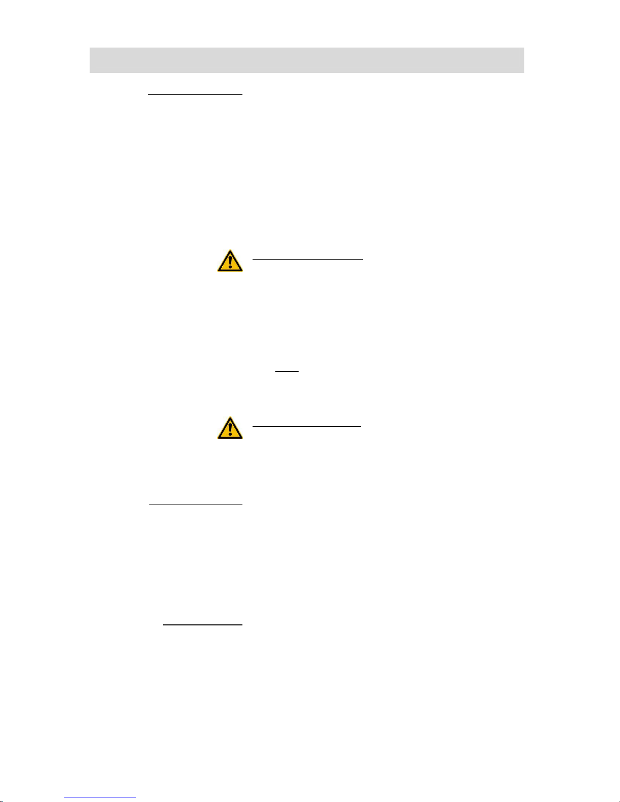
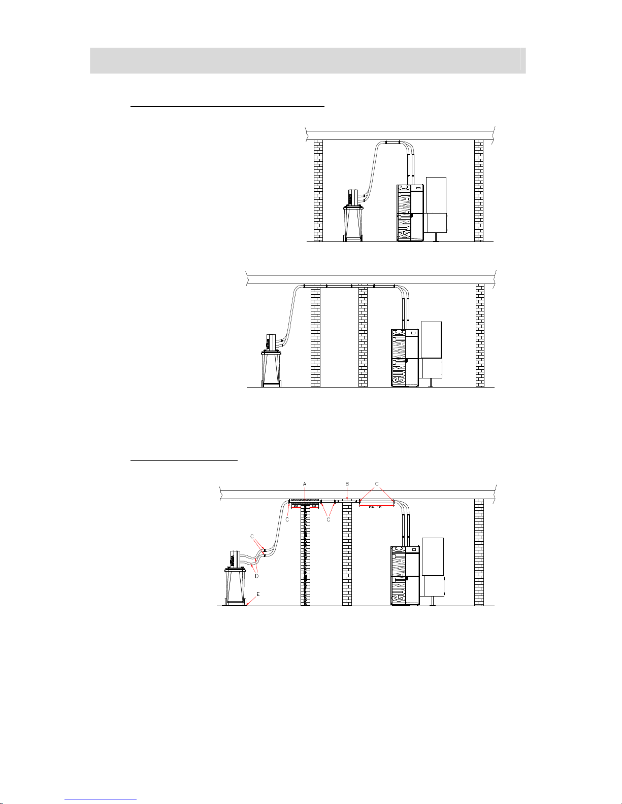
2.7 EXAMPLES FOR PLANING
BC-01
Example 1 Construction with Flex fuel supply next to the heating room.
The maximum length of agitator is 5m.
The maximum suction length is 25 m.
Minimum 2 fire security wristbands needed – please respect the minimum fire security rules!
Example 2 Machine with Flex fuel supply with annother building section.
The maximal length of extracting screw amounts 5 m.
The maximal suction length is 25 m.
Minimum 2 fire security wristbands needed – please respect the minimum fire security rules!
Example 3 Machine with Flex fuel supply with annother building section.
The maximal length of extracting screw amounts 5 m.
The maximal suction length is 25 m.
Minimum 2 fire security wristbands needed – please respect the minimum fire security rules!
14
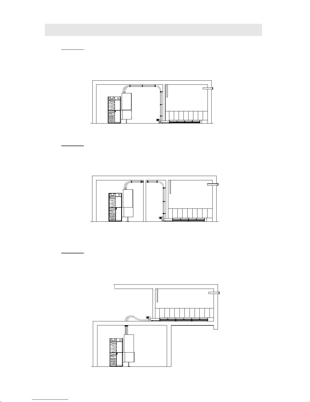
Example 4 Consruction with BOX- fabrictank direktly above the heatingroom.
The maximum Suctionlength is 25 m.
Minimum 2 fire security wristbands needed – please respect the minimum fire security rules!
Example 5 Construction with BOX- fabrictank in a other building section.
The maximum Suction length is 25 m.
Minimum 4 fire security wristbands needed – please respect the minimum fire security rules!
Example 6 Cascade construction with 2 FLEX-R directly below with the heating room.
The maximal length of extruding screw constitudes 5 m.
The maximum suction length is 25 m.
No fire security wristbands needed – please respect the minimum fire security rules!
15
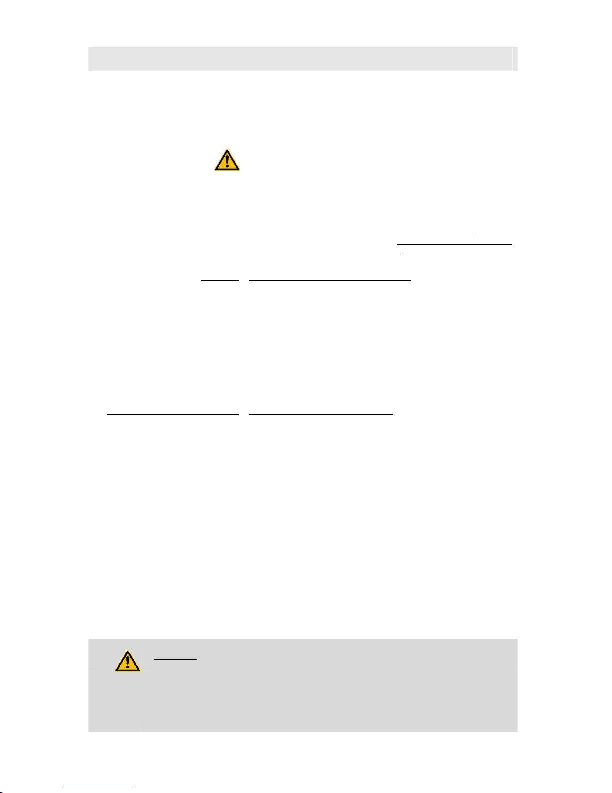
2.8 AUTOMATIC ASH SUCTION SYSTEM
PC-01
The following Introductions are for Device
planning- for installation of ash vacuum suction
system there is another Introduction included.
Optional there is a automatic ash vacuum system. The
accumulated ash will go through the firing build Feedsystem
and flexible metal tube in a big removable ashton. The
deashing is automatically.
Retofit the system It´s possible to retrofit the ash vacuum suction system, if the
minimum difference between the wall and the system ist 60
cm.
A → 153 cm
B → 59 cm
C → 72 cm
D → 107 cm
Construction side: If possible, you have the opportunity to plan the ash ton at a
ground level beside the boiler’s body. Basic requirement for
the construction is a good lifting through the installation site,
The ash ton must have a 25 cm minimum difference to
inflammable materials. You have to be a look that there is no
inflammable ground.
Not permitted construction side for an ash ton:
• in an garage
• in the atmosphere in living rooms;
• in storerooms with inflammable materials or gases.;
16
Permitted Construction places for the ash ton:
• in the boiler room
• in an secondary
room
Hauling of a suction pipe through fire zones
A → wall penetration with Rockwoolpipesprialclamp;
B → wall penetration with boiled Steel pipe;
C → fire security clamps 54 – 60;
(maximal 1 m difference)
D → flexible suction metal tube
(minimum 10 cm difference)
E → not inflammable mad
17
2.9 HEATING CIRCLE RULE
PH-01
The heating circle rule is optional offered.
You can decide between a MKR set or a wall mounted MK 261
set.
●
per construction 3 controlled by atmospheric condition rules
possible
●
per construction could be actived just 1 MKR Set boiler
●
pro Machine there are 3 remote control möglich;
●
per heatingcircle one analogue room unit possible
Exceptions at five sensors are buffer management
Please note the information in section 5- sensore buffer management of
chapter 7.1 and buffermanagement HP0 !
Set-MKR Following functions could be activated:
Heatingcircle
● Warmwater-Memory
Heatingcirle 0
optional avalible
........
● pump heating circulation
● aditional warmwater memory
● external heatingcirculation
Heatingcircle 1
optional avalible
.......
● Pumpenheizkreis
● gemischter Heizkreis
Heatingcircle 2
optional avalible
.......
● Pumpenheizkreis
● gemischter Heizkreis
wall mounted model set-MK261 Following funtions could be active:
Heatingcircle WW
● warmwater- memory
Heatingcircle 0
optional
.................
● pumpingheatingcircle
1)
● third mixed heatingcircle
Heatingcircle 1
optional
.................
● pumpingheatingcircle
● mixed heatingcircle
Heatingcircle 2
optional
.................
● pumpingheatingcircle
● mixed heatingcircle
Trunk link
optional
.........................
● feederpump
(ZUP)
● dumping device pump
(PUP)
● cargo pump
(LAP)
2)
● extension
(ERW)
3)
● third mixed heatingcircle
adition
optional
..............................
● aditional warmwater memory
● external heatingcircle
4)
● third mixed heatingcircle
INFOBOX
1) the third mixed heatingcircle could be actived, if the functions trunk link and addition are not used.
2) through „ERW“ function a heating circle controller with trunk blink can be assigned an other heating circle controller
3) if the function „third mixed heatingcircle“ is activated, the trunk blink functions are not availible.
4) if the „third mixed heatingcircle“ is activated, the additional functions are not availibe.
 Loading...