

Page 1

DDiiggiittaall EExxhhaauusstt CCOO AAnnaallyysseerr wwiitthh PPuullssee PPuummpp
GASTESTER
Handbook G4125
www.gunson.co.uk
Page 2

Page 3

33
GASTESTER
Digital Exhaust CO Analyser with Pulse Pump
INDEX Page
1. Contents 4
2. Assembly 4
3. Descriptions and controls 5
4. Preparations before use 5
5. Instructions for use 6
6. Further information 7
7. Common problems 8
8. Multiple carburettors 9
9. Carburettor Adjustments – General Information 10
10. Single Fixed Venture Type 12
11. Single Variable Venture Type 12
12. Idle Adjustment 13
13. Technical Specification 18
14. General Warning 18
15. Warranty 19
GGuunnssoonn GGaasstteesstteerr
Page 4

44
Gastester is an exhaust gas analyzer that works on the “Hot Wire” or “Thermal
Conductivity principle. According to this principle, the thermal conductivity of
exhaust gas varies in proportion to the amount of carbon monoxide present.
CO Function
Calibrated range: 0-10% CO
(indicates uncalibrated to 20% C)
Accuracy: +/- 0.5% CO Typical
(Throughout the indicated range 0.5% CO to 6.5% CO)
1. Contents
1. Gastester instrument including collector box and pulse pump/water trap assembly
2. Metal exhaust probe with retaining springs
3. Flexible pipes (3)
4. Instruction handbook
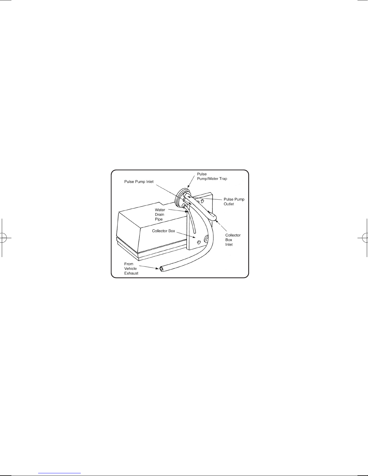
2. Assembly
• Warming the various pipes will assist assembly. Only the connection to the vented
collector box inlet needs to be pressed fully home.
• Press the shortest pipe onto the lower boss of the Pulse Pump/Water Trap as shown
in the diagram Figure 1. This is the automatic water drain.
• Connect the other plastic pipe between the Pulse Pump outlet and the collector box
inlet. (This connection is intentionally vented at the inlet boss). The connection to the
collector box inlet needs to be pressed fully home.
GGuunnssoonn GGaasstteesstteerr
FFiigguurree 11
Page 5
55
3. Descriptions & Controls
DISPLAY This is calibrated in volume percent carbon monoxide (CO%)
CALIBRATION CONTROL This is used to set the reading of the display to show 2.0% at
the start of the tests, before the probe is inserted into the exhaust pipe. (NB: The
calibrate position represents what the instrument should register when the probe is in the
air. It is coincidental that air should measure the same as exhaust gas with 2% CO).
When the probe is subsequently inserted into the exhaust pipe, the display of the
instrument may increase or fall from the calibrate condition.
TWO CORE CABLE WITH CLIPS (for connecting to the car battery)
EXHAUST PROBE. The metal pipe is for insertion into the exhaust pipe and is retained
in position by the metal springs which press against the inside of the exhaust pipe.
NB In use the pipe from the exhaust probe should slope down continuously to the
Pulse Pump/Water Trap so that water runs down and may be automatically
expelled from the drain pipe.
4. Preparations before use
• Any service maintenance such as air filter renewal, tappet adjustment, carburetor maintenance,
ignition maintenance including ignition timing, should be carried out before setting the carburetor
or fuel injection mixture adjustment. Petrol mixture setting should be the FINAL ADJUSTMENT
in any engine tuning work.
• Carbon monoxide is an EXTREMELY POISONOUS gas and any work on the car with the
engine running should therefore be carried out in the open air. Take care not to breathe in
gases when using the gas tester.
• Study the workshop manual for the particular car (or consult the information given later in this
booklet) to identify the correct adjustment screws, that control the mixture strength and the
idle speed. Make a note of the initial position of the adjustments before commencing work.
• The car should be thoroughly warm before the tests begin. It is not enough to leave the car to
warm while parked. The car should be taken for a drive and the tests not commenced until
water temperature, exhaust system and engine are running at normal temperature.
• Have to hand the correct tools for making the necessary adjustments. If the manual
recommends a CO level at a particular engine speed, then a tachometer would be an
advantage.
GGuunnssoonn GGaasstteesstteerr
FFiigguurree 22
Page 6

5. Instructions for use
Ensure that the car is thoroughly warm as mentioned above, that it is parked in a
convenient position in the open air, with the handbrake applied.
NB: THE INSTRUMENT SHOULD NOT BE PLACED DIRECTLY IN THE EXHAUST
STREAM. CLEAN AIR IS REQUIRED IN THE REFERENCE CELL FOR ACCURATE
READINGS.
1. Place the Gastester Professional on a convenient flat surface close to the vehicle’s
exhaust pipe outlet. Switch off the engine temporarily while making connections.
Connect the RED (+) and BLACK (-) clips to the vehicle’s 12 V battery (Do not use
this Gastester with 6v or 24v batteries)
2. The probe should be fitted to the instrument but do not insert the exhaust probe into
the exhaust pipe at this stage
3. Restart the engine and allow a minimum period of eight minutes with the instrument
probe in the air. Set the calibration control to achieve 2% on the CO range and
observe the display for a further 2 minutes minimum to ensure that the reading
has stabilized.
4. IMPORTANT if it has not stabilized allow a further 2 minutes before attempting to
measure exhaust CO level.
5. During the warm up period other ranges will give accurate readings and it is therefore
useful to check and adjust engine idle RPM.
6. Switch to the CO range with the probe in air.
Do not insert the exhaust probe into the exhaust pipe at this stage
7. Use the rotary calibration control to carefully reset to the CALIBRATE reading of
2.0% CO. The instrument displays two decimal places on the CO range as a result of
the high resolution display. The last decimal place is insignificant and when setting to
2% in air the user should not be concerned if 2.00% exactly can not be obtained.
Having set the CALIBRATE condition do not move the instrument, or move to a
different location during subsequent CO tests.
8. When the probe is subsequently inserted into the exhaust pipe, the display of the
instrument may increase or fall from the CALIBRATE condition, depending on
whether the exhaust has more than, or less than, 2% CO.
9. Ensure that the engine is set to the idle RPM stated by the manufacturer. Now insert
the probe into the vehicle’s exhaust pipe to a minimum of 3/4 of its length, i.e. 8” or
20cm. In order for the automatic water drain to function, the probe pipe should fall
continuously from the exhaust end to the inlet end to allow water droplets to run
down. Otherwise the water will collect at the lowest point and will have to be drained
manually.
10. Wait for a period of 15 seconds for the meter to respond and a further 1 minute to
stabilize (the reading may overshoot before returning to a steady value, particularly
during the initial measurement).
11. Make a note of the reading and observe the display for a further one or two minutes
to ensure that the reading is indeed steady and within tolerance for the vehicle
concerned. If the reading is not between the manufacturer’s recommended maximum
and minimum, or is not below that specified as a legal requirement, then adjustment
of the carburettor or fuel injection system will be required.
66
GGuunnssoonn GGaasstteesstteerr
Page 7

77
12. If adjustment is required, make a small alteration to the mixture screw, and correct
the idle speed by adjusting the idle speed screw (or throttle bypass screw if fitted see figure 6 & 9). Do this repeatedly in small increments, under these conditions the
reading should stabilize in less than one minute at each mixture setting.
13. When the test is complete REMOVE THE EXHAUST PROBE PIPE and switch off the
engine. Allow a period of at least 5 minutes or at least 10 minutes in still air
conditions with little breeze, for air to purge the exhaust from the instrument. This
period in air with power on cleans the sensor before storage and also allows a check
to ensure the display returns close to the 2% setting indicating that there has been
little drift in calibration.
NB: A final reading of 1.8% in air for example would suggest that the last exhaust
measurement was approx 0.2% lower than the displayed level. While this is perfectly
acceptable when setting to approx 3% to ensure that a vehicle passes a 4.5% maximum
legal requirement, it does represent a more significant error if setting to a
manufacturer’s recommended 0.5% CO. On occasions it may be necessary to repeat a
test if calibration drift is excessive (drift is reduced by keeping test duration short and
allowing a long warm up).
6. Further Information
It should be noted that an engine, even in good overall condition, will show a fluctuation
in idle CO over a period of time, of typically 0.5%. Bearing in mind this fluctuation, and
also errors and drift in the instrument, the user should aim to set the average CO reading
to be midway between the limits set by the manufacturer, or at a reasonable margin
below the prescribed legal limit. If the CO level is correct HC levels should also be low if
general engine condition/adjustment is reasonable.
Periodically, during the tests, examine the lowest point of the transparent plastic pipe to
see if it contains water to a degree that might impede the flow of gas, and if it does,
remove the pipe at the instrument gas inlet end and clear the pipe by allowing the water
to drain out, then reconnect the pipe and carry on with the tests. If the transparent pipe
falls continuously from the exhaust to the pump the automatic drain should operate and
keep the pipe clear of water.
NB: Operation of the pulse pump will usually be audible as the pulsations in the
exhaust cause the internal diaphragm to vibrate. If the instrument ceases to
respond to changes in mixture setting or the sound from the pulse pump becomes
irregular, check the sample pipe for collected water.
The calibration of the instrument may be checked at any time. Simply remove the
exhaust probe and wait at least five minutes or at least ten minutes in still air conditions
with little breeze, for the exhaust gas to disperse from the collector box. If necessary, the
calibration may then be adjusted using the calibration control knob. Periodically check
the calibration of the instrument during particularly extended tests.
Some motor car engines will not readily “tick over” at idle speeds for long periods.
The speed may become erratic, and engine misfiring may occur. With the prolonged
testing of such engines, it may be necessary to occasionally “purge” the engine by, for
instance, increasing the speed to 2000 rpm - 3000 rpm for 15 seconds. This may be
done at any time during the tests but the exhaust probe should be removed beforehand.
VEHICLE REPAIR IS ADVISED,
GGuunnssoonn GGaasstteesstteerr
Page 8

88
If the exhaust pipe has a curved inlet it may be necessary to slightly bend the metal
exhaust probe to give better fit. This should be done very carefully using slight bends in
several places rather than a single big bend in order not to kink the pipe.
FULL INSERTION IS ESSENTIAL FOR ACCURATE READINGS
Engine fuel systems are usually designed so that the mixture automatically becomes
weaker at speeds above idle, except under rapid acceleration when the mixture is enriched
Gastester is designed to work at engine tick-over speeds; however it will also give a
reliable reading at higher engine speeds.
VIOLENT FULL THROTTLE ACCELERATION TO HIGH ENGINE SPEED SHOULD BE
AVOIDED WHILE THE PROBE IS IN THE EXHAUST PIPE AS THE PULSE PUMP
DIAPHRAGM AND PROBE PIPE MAY SUFFER DAMAGE IN EXTREME CIRCUMSTANCES.
To test mixture weakening at higher RPM, increase the engine speed in increments of
approximately 300 RPM to 400 RPM up to a maximum of 2500 RPM, observing the reading
between each adjustment. (Remember that the instrument may take 15 seconds to respond to a
particular adjustment. The CO level should fall progressively and stay low during a gradual
increase in speed.
The mixture enrichment for acceleration (accelerator pump/air valve damper) can be tested by
rapid opening and immediate release of the accelerator. Opening to half throttle should be
sufficient. Within a few seconds of this operation the Gastester CO indication should increase
before returning to its previous setting. The degree of increase will vary according to how this
procedure is carried out and also with the type of fuel system. A fixed choke carburettor with
accelerator pump will usually give a more pronounced increase than a variable choke carburettor
or fuel injection system.
Use only a 12 volt car battery in good condition as power supply. A faulty or flat car battery may
not be able to supply adequate current to the instrument (Gastester Professional draws about 0.8
amps), resulting in errors in use and difficulty in calibration.
7. Common Problems
Q. The car does not drive well with the correct idle mixture setting.
A. This is a common complaint. On older vehicles the cause is likely to be a fuel system fault which
creates a weak mixture just above idle speed. Clean the idle jet and idle air bleed jet on fixed
choke carburettors. Check for needle/jet wear on variable choke carburettors (above 40,000
miles). These are available as spare parts. heck acceleration enrichment device.
Q. The correct mixture setting cannot be achieved/Setting is continually too rich.
A. Clean the idle air bleed jet and air passage on fixed choke carburettors. Check for severe needle
jet wear on variable choke carburettors. Check for high fuel level in the float chamber. Check cold
start device.
Q. Setting is continually too weak.
A. Clean the idle jet on fixed choke carburettors. Check needle and jet for disengagement from
adjusting device or sticking on variable choke carburettors. Check for air leaks.
Q. The engine misfires or is unstable at idle with the correct mixture setting.
A. Misfire/engine instability causes increase in HC reading and potential emission test
failure even with correct CO level. Check for general engine condition – compression
pressures, sparking plugs etc. Check for air leaks, these may cause severe variation
in mixture between cylinders. Investigate mixture quality i.e. fuel air mixture may not
be finely atomized due to partially blocked air jets or prematurely feeding main jet
GGuunnssoonn GGaasstteesstteerr
Page 9

99
system caused by high float chamber level etc. Check for advanced ignition timing,
tight valve clearances, slow idle speed
Q. The mixture setting drifts
A. Check for leaking float chamber needle valve if CO level steadily increases with prolonged idle.
Check for high float chamber level. Check Gastester CALIBRATION in air, slight drift will occur
during extended operation. Good stability should be obtained over a period of five minutes or
more. A variation of, for example 0.5% CO at CO is not uncommon on an engine which is in
good working order.
Q. Gastester gives errors or slow/no response to mixture changes.
A. Check for water in the probe pipe and adequate probe insertion; minimum 8 inches/20 cm. If a
baffled silencer with no tailpipe is fitted, as on some motorcycles, temporary restriction of the
exhaust outlet or temporary fitting of a tailpipe extension may be the only way to achieve
acceptable results.
NOTE:
In use the pipe from the exhaust probe should preferably slope down
continuously to the Pulse Pump/Water Trap so that water runs down and may be
automatically expelled from the drain pipe. Operation of the pulse pump is clearly
audible as the internal diaphragm vibrates with pulsations from the exhaust, if
response is obtained at higher than idle speeds only, Pulse Pump may need
replacement. (Alternatively twist the pump cap on the body to re-seat the diaphragm).
If the pump is working, the vehicle mixture adjustment may be ineffective.
Q. Gastester Professional cannot be set to the Calibration Condition in air
after warm-up.
A. First check that the unit is switched correctly to CO RANGE and is used in a
horizontal position (the unit will not operate correctly if instrument is significantly
inclined or if the instrument angle is changed after calibration). Ensure that the unit is
connected to a car battery (NB: a 12v dry cell battery or a faulty car battery can
not provide enough current and are unsatisfactory). Ensure that the unit is
correctly warmed up (allow at least 10 minutes). Ensure that the unit is being
calibrated to the 2% CO condition, NOT at zero). Ensure that the probe is in air, not
in the exhaust pipe. If these checks do not resolve the problem, it is possible that the
instrument has “drifted” generally due to collector box contamination or damage due
to impact (the instrument is more susceptible to damage when warm and in use).
The unit should be returned to The Tool Connection for service.
8. Multiple Carburettors
Where two separate carburettors are fitted, (not to be confused with a Twin choke
carburettor) two extra complications arise. Firstly the air flow through the carburettors must
be accurately balanced before any mixture setting can be undertaken. This can be done
using the Gunson’ Carbalancer, or less accurately with a tube to listen to the air intake hiss.
Secondly there will be separate mixture adjustments which must be synchronized. In the
unlikely event that cylinders fed by each carburettor have totally separate exhaust, CO can
be checked in each exhaust to set the respective carburettor. When the exhaust is common
to all cylinders another method must be used. One method is to count the turns of the
mixture adjusting screws from the fully closed position (or jet flush with the bridge for
variable venturi types) and then ensure that the screws are kept to the same number of turns
throughout adjustment. An alternative (and better) method is to use a Gunson Colortune to
GGuunnssoonn GGaasstteesstteerr
Page 10

1100
set the mixture strengths equal at some point, then to ensure that the screws are turned the
same amount during subsequent adjustments.
9. Carburettor Adjustments – General Information
There are literally hundreds of different types of carburettor in use today, and finding the
appropriate screws that control idle mixture strength and idle speed can pose quite a
problem. Wherever possible, the user is advised to consult a detailed workshop manual
for the particular car, but the following notes are provided for use when such information
is not available.
Firstly it should be mentioned that it is a legal requirement that all carburettors have
either a method of sealing the adjusting screws, or require the use of a special tool to
enable adjustments to be made. In some ways this has been a retrograde step, it may
stop “tinkering” by an unskilled owner but wear of the various parts takes place during
the life of the car, and mixture adjustment is frequently ignored until it becomes
troublesome in terms of starting, performance or economy. Seals are usually thin metal
or plastic plugs which are destroyed on removal, and are usually removed using a sharp
screwdriver bit or short self-tapping screw. Other types offer a limited adjustment which
can be increased by removal of a cap, and some cover seals have a removable centre
section allowing access to the adjustment. The vehicle manufacturer will invariably
recommend that the seals are renewed after adjustment, but this is frequently ignored by
the service trade or vehicle owner, particularly after the service warranty has expired.
In some countries, particularly the USA and Japan, this would be an offence.
Carburettor types can be divided into those that have a separate fuel circuit for idle, and
those without a separate idle circuit. Figure 6 shows a typical arrangement of separate
idle circuit. The mixture is made richer (i.e. CO higher by screwing the screw out)
In such carburettors, idle speed can be of the adjustable throttle stop type (Figure 3-7)
An alternative arrangement of separate idle fuel circuit with idle speed adjustment of the
throttle bypass type is shown in Figures 9/10. In this type, idle speed is controlled by a
screw controlling the flow of air and fuel through a bypass channel, and not by varying
the position of the throttle plate. In such types, the idle speed adjustment and idle
mixture adjustment are usually located near to each other, on the same side of the
GGuunnssoonn GGaasstteesstteerr
FFiigguurree 33
Page 11

1111
carburettor. On certain types, the bypass channel may have its own mixture adjustment
(shown dotted), for example some Solex EEIT carburettors. In this Solex twin carburettor,
the mixture to both barrels is adjusted using the mixture bypass screw, the two
conventional mixture screws normally remaining unaltered. It should be noted that with
this type, when the bypass screw is used to change the engine speed, the mixture is
affected also. It is therefore important to correct idle speed after each mixture
adjustment, and to work in small increments of adjustment. It should also be noted that
when a throttle bypass screw is fitted, the throttle stop screw will normally be locked or
sealed, and in such units, the throttle stop screw should not be disturbed.
Carburettors without a separate idle mixture circuit are typified by the SU and CD
horizontal variable venturi types. Mixture throughout the speed range is governed by a
long tapered needle in a jet. Lowering the jet or raising the needle by manual adjustment
causes a richening of the mixture throughout the operating range of the engine.
The following notes describe particular types of carburettors and the methods of adjustment.
GGuunnssoonn GGaasstteesstteerr
FFiigguurree 44
FFiigguurree 55
FFiigguurree 66
Page 12

10. Single Fixed Venturi Type
This is one of the simpler forms of carburettor with a single air inlet and throttle plate, with a
variety of air and petrol metering jets and channels. The main jet and associated main air jet
and emulsion tube etc provide an aerated “emulsion” which is fed to the venturi at speeds
above idle. This already aerated fuel and air mixture breaks down further in the airstream.
The idle circuit is separate and also has a fuel and an air jet which feed an aerated mix to a
drilling downstream of the throttle plate, further drillings are found in the area of the throttle
plate. Just above the idle drilling would be found “progression” holes which are progressively
uncovered by the movement of the throttle plate and increase the fuel flow when exposed to
the manifold depression (or vacuum). This supplements idle fuel flow until the main fuel
discharge in the venturi is well established. All of these fluid circuits are fed from a small
reservoir of fuel whose level is controlled by a float and needle valve.
11. Single Variable Venture Type
This type of carburettor consists of a single air inlet (but more than one carburettor is
sometimes fitted: see Section 8, Twin and Multiple carburettors), a throttle plate (or
butterfly), and an air valve or a piston which closes off the air inlet to which is attached a
tapered fuel metering needle. This needle runs inside a fuel jet which draws mixture from a
small reservoir of fuel. The level of fuel is controlled by a float and valve. At idle, when the
throttle is nearly closed, the air valve is almost completely closed and the tapered needle
which is attached to it restricts the flow of fuel to a great extent. As the throttle is opened
the air valve is drawn upwards allowing more air to enter and the needle is drawn out of the
jet allowing more fuel to flow. If the throttle is opened fully at low RPM the air valve rises
about halfway. As the engine speeds up and draws in even more air the air valve will
continue to rise. Thus the top half of the needle governs part throttle mixture and the lower
half (slim end) governs full throttle mixture. Mixture enrichment during acceleration is
achieved using an oil filled damper which reduces the rate at which the air valve can rise.
Two types of needle are fitted:
(a). A rigidly fixed needle which should not touch the jet. In some cases after stripping
the carburettor it is necessary to centralize the needle and jet during re-assembly
(this is a very early type).
(b). A needle which is spring loaded against the side of the jet: when in good condition
this type gives improved accuracy of fuel metering. (Replace at 50,000 miles / 80,000
km intervals).
NB: The needle housing should not be rotated as the direction of spring loading
will be affected. Fuel metering needles are manufactured to within .0025mm
(.0001
”
) and should be handled carefully. SU type HIF and Stromberg CDSE
types have a temperature compensating device fitted but other SU and
Stromberg CD types should be set when the carburettor is warm to the touch
but not hot, to achieve maximum setting accuracy.
GGuunnssoonn GGaasstteesstteerr
1122
Page 13

12. Idle Adjustment
The idle speed screw generally acts on the throttle spindle to which the accelerator
linkage is connected: this will give very fine adjustment of the throttle. The mixture screw
(also affecting mixture at high speeds) is located in different positions on different types.
SU TYPE
On early versions this is generally a hexagon nut underneath the carburettor and is
screwed up to weaken (clockwise looking from underneath). Other types, HSB, HD, etc.,
have a screw which raises and lowers the jet through a system of levers. HIF types have
a screw which is located behind removable plug in the right hand side of the carburettor:
screwing in clockwise enriches the mixture.Occasionally adjustment is on the left (one
left, one right on twins).
CD TYPE
On early versions there is, generally underneath the carburettor, either a large slotted
screw or, in later types a castellated bush which requires a special tool for easy
adjustment. It is screwed up to weaken (clockwise looking from underneath). Other types
(adjustable needle) are plugged underneath and have a slot in the air valve (piston) guide
rod. Remove damper and look inside to check for this. (The slot is across the smallest
tube which is visible). An adjusting tool is also required here. (See Fig 8 for alternative
adjusting tools)
TWIN VENTURI CARBURETTORS (TWIN CHOKE) PROGRESSION TYPE
On this type two venturis are incorporated in the same casting. One throttle plate opens
before the other (observe while operating the throttle linkage). At low speeds and for idle
mixture adjustment this type can be considered similar to the single choke type, all
adjustments being carried out on the barrel which opens first. The Pierburg 2E3 shown in
(Fig 7) has a diaphragm operated second barrel and the idle adjustment is by the throttle
stop screw and idle mixture screw shown. On the G.M. Varajet carburettor shown in
Figure 9 the secondary barrel is of variable venturi design. This has no bearing on the idle
setting which is of the by-pass type. Idle speed is adjusted on the throttle by-pass screw.
TWIN VENTURI CARBURETTOR SIMULTANEOUS TYPE
On this type the two venturis are incorporated in the same casting and both throttle
plates operate at the same time. There is usually no need to balance the air flows
through the two barrels. They are often linked by a single throttle spindle. Balancing of
the two mixture screws is obtained by setting to the same number of turns open.
GGuunnssoonn GGaasstteesstteerr
1133
FFiigguurree 77
Page 14

1144
GM VARAJET
PETROL INJECTION SYSTEMS
Modern fuel injection systems can be either of the continuous type (e.g. Bosch K & KEJetronic), or intermittent type (e.g. Bosch L, LE, LE2-Jetronic, Motronic, Lucas LH etc)
Adjustment screws are provided for idle mixture (CO). In some versions idle speed is not
mechanically adjustable. The manufacturer’s instructions should be carefully followed for
GGuunnssoonn GGaasstteesstteerr
FFiigguurree 88
FFiigguurree 99
Page 15

particular models. The illustrations below show examples of types of adjustments.
Some older types of system (e.g. Triumph PI) used separate throttle plates per cylinder
and a common idle mixture screw. With this type it is essential to obtain an accurate
balance through each throttle plate before any mixture setting is undertaken. This can be
done using Carbalancer or Colortune. Where separate control screws are provided for
each cylinder, adjustment should remain synchronized, by using the same turns for each
screw during adjustments.
FFiigguurree 1111
FFiigguurree 1122
FFiigguurree 1100
GGuunnssoonn GGaasstteesstteerr
1155
Page 16

GGuunnssoonn GGaasstteesstteerr
1166
EXHAUST GAS ANALYSIS
Carbon monoxide (chemical symbol CO) is a colorless, odorless, but extremely
poisonous gas that is present in the exhaust gas of petrol-engine vehicles. The amount
of carbon monoxide in the exhaust gas is an accurate indicator of the air/fuel mixture
strength being supplied to the engine, and for this reason motor manufacturers use the
measurement of carbon monoxide in the engine exhaust as the recommended method
for setting the air/fuel mixture strength on carburettors and fuel injection systems. The
recommended percentage of carbon monoxide in the exhaust at engine idle (i.e. tick over
speed) is usually specified in the engine maintenance handbook for each vehicle.
Manufacturers typically specify a CO level somewhere within the range 0.5% to 3.5% by
volume, and often give an upper and lower limit for the recommended setting, for
example, a manufacturer may specify 0.5% to 1.5% CO.
Alternatively, the data may be given in the form 2% + .5% CO (which means between
1.5% and 2.5%). Less commonly (and less exactly) a manufacturer may simply specify a
maximum limit e.g. below 3.5% CO.
Carbon monoxide only amounts to a relatively small percentage of the total volume of
exhaust gas. The bulk of exhaust gas comprises nitrogen (N2), carbon dioxide (CO2),
water vapour (H2O). Hydrogen (H2) is also present, particularly in association with
carbon monoxide. Oxygen (O2) can be present either due to a weak mixture, or due to
engine misfiring. Very small amounts of other substances are also present in exhaust
gas, such as unburnt or partially burnt fuel (generally referred to as hydrocarbons) and
also some oxides of nitrogen. The way that the composition of exhaust gas varies with
petrol/air mixture strength is illustrated in Figure 13.
It can be seen from Figure 13 that at a particular air/fuel mixture ratio (somewhere near
14.7: 1 for petrol engines) the amount of oxygen present in the air that is entering the
engine is exactly that required to completely burn all the petrol to carbon dioxide and
water. There is therefore very little carbon monoxide in the exhaust, and no free oxygen.
This particular ratio of air and petrol is known as the stoichiometric ratio. At this ratio, the
percentage of carbon dioxide in the exhaust is at a maximum, and the percentage of
carbon monoxide is very low.
In mixtures richer than the stoichiometric ratio (i.e. more fuel, or less air), there is
insufficient oxygen in the air to burn all the carbon in the fuel completely to carbon
FFiigguurree 1133
Page 17

GGuunnssoonn GGaasstteesstteerr
1177
dioxide. Some carbon therefore exists in the form of carbon monoxide, and the richer the
mixture the more carbon monoxide and the less carbon dioxide there is in the exhaust. It
can be seen from Figure 14 that motor manufacturers generally specify a mixture strength
at idle that is slightly richer than the stoichiometric ratio. Under some conditions, such as
starting an engine from cold, or during acceleration, very much richer mixtures are used.
In mixtures weaker than the stoichiometric ratio (i.e. less fuel, or more air), there is more
oxygen in the air than required for complete combustion of the petrol, and the surplus
oxygen appears in the exhaust gas. The level of carbon monoxide is very low, since
virtually all the carbon in the petrol is completely burnt to carbon dioxide. There is however
a smaller percentage of carbon dioxide present in the exhaust than at the stoichiometric
ratio of air and fuel, simply due to the diluting effect of the extra air passing through the
engine. Engines are commonly designed to run with such weak mixtures under light load
driving conditions, though not at idle.
An engine will run, indeed run quite well, at mixtures that are richer or weaker than those
specified by the motor manufacturer. However, at settings richer than the manufacturer
recommends, there is a loss in economy, and at very rich settings, typicall 8% to 10% CO,
the onset of poor running occurs, characterized by the particular engine sound that is
known as “hunting”.
At settings weaker than the manufacturer recommends there is poor engine performance
and “flat spots”, and at very weak settings, typically 2% to 4% oxygen, the engine will not
run at all. Note that at very weak settings it is inappropriate to speak of the CO level, since
CO reaches a very low level below which it hardly changes for further weakening of the
mixture and some other indicator of mixture strength must be used, such as oxygen.
It has already been mentioned that motor manufacturers specify a CO level at a particular
engine idle RPM, but that the CO level under other engine running conditions will generally
be different from this. A richer mixture is used when starting the engine from cold, a weaker
mixture when driving under light power, a richer mixture when accelerating, etc. However,
the user does not need to be aware of this. It is simply necessary to set the mixture
strength at idle as specified by the motor manufacturer, and the carburettor or fuel injection
system then automatically sets the mixture right at other engine conditions.
Gastester is an exhaust gas analyzer that works on the “Hot Wire” or “Thermal
Conductivity principle”. According to this principle, the thermal conductivity of exhaust
gas varies in proportion to the amount of carbon monoxide present.
FFiigguurree 1144
Page 18

GGuunnssoonn GGaasstteesstteerr
1188
13. Technical Specification
CO Function
Calibrated range: 0-10% CO (indicates uncalibrated to 20% C)
Accuracy: +/- 0.5% CO Typical (Throughout the indicated range 0.5% CO to 6.5% CO)
14. General Warning
This equipment has been designed to operate in the harsh environment close to
spark ignition engines but the user should be aware of the following:
• Spark ignition engines and related electronics can emit high levels of interference
which could effect test and maintenance equipment together with other electrical
items such as radio or television receivers, computers etc.
• Any interference emitted from the engine area could be increased by opening the
engine compartment cover.
• Making electrical connections to the vehicle wiring loom or the vehicle battery.
• Any faulty components particularly those associated with the ignition system.
• If this equipment has any display which behaves in an erratic nature the user is
advised to refer to the advice given in the detailed instructions to minimize the
possibility of interference. In cases of difficulty the user is advised to check for
the following.
• A faulty vehicle battery or poor connections to it.
• Poor ground connection to engine or other electrical equipment.
• Faulty ignition components particularly rotor arms, ignition coils or HT leads with an
internal break or with a resistance outside vehicle manufacturers limits.
• The user is therefore advised, due to the potential emitting of interference,
that vehicle main tenance and testing should be undertaken with due care and not in
an area close to sensitive electronic equipment.
Page 19

GGuunnssoonn GGaasstteesstteerr
1199
GGuunnssoonn 0033//22000088
15. Warranty
This warranty is in addition to the statutory rights of the purchaser.The Tool Connection has
made every effort to ensure that this product is of the highest quality and value to the
customer. However, The Tool Connection can accept no responsibility for consequential
damage howsoever caused arising from the use of this product.
All technical enquiries regarding this product should be made to:
The Tool Connection Technical Service Department: +44 (0) 1926 818181
Please note that The Tool Connection cannot provide technical information or advice or
service data on particular motor vehicles.
If this product should require service or repair, it should be returned to:
The Tool Connection
Kineton Road
Southam
Warwickshire
CV47 0DR
England.
Please give full details of faults requiring attention when sending goods for service
or repair.
Page 20

 Loading...