

Page 1

Handbook
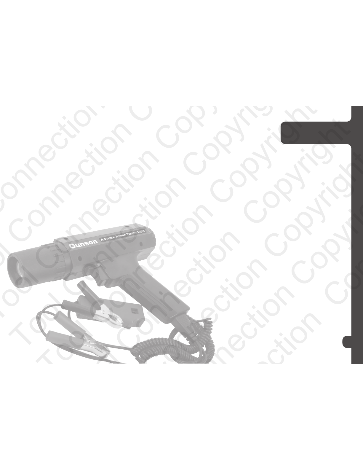
Advance Xenon
Timing Light
Part No. 77008
If this product fails through faulty materials or workmanship, contact our
service department direct on: +44 (0) 1926 818186. Normal wear & tear are
excluded as are consumable items & abuse.
Guarantee
Tool Connection Copyright
Page 2
3
Index
SAFETY PRECAUTIONS ........................... 4
WHAT IS IGNITION TIMING? ..................... 5
WHAT IS ADVANCE TIMING LIGHT? ........ 6
PRODUCT DESCRIPTION .......................... 7
NSTRUCTIONS FOR USE .......................... 8
ADDITIONAL INFORMATION ..................... 9
a. 6/24 VOLT VEHICLES
b. MAGNETO IGNITION SYSTEMS
c. ROTARY ENGINES
d. RETARDED IGNITION
DIAGNOSTIC TESTS ................................ 10
a. Testing Centrifugal Advance Mechanism
b. Testing Vacuum Advance
c. Testing Vacuum Retard
d. Detection of Distributor wear or inaccuracy
e. Effects of incorrect ignition timing
GENERAL WARNINGS .............................11
GUARANTEE ............................................. 12
Tool Connection Copyright
Page 3

What Is ignition
Timing
5
Safety Precaution
4
Using this timing light necessarily involves working under the bonnet while the engine is running.
This is a potentially hazardous situation, and the user should take every precaution to avoid any
possibility of injury. The following guidance should always be followed:
• Never wear loose clothing, particularly ties, long sleeves etc that can catch in moving engine
parts, and always tie-up or cover long hair.
• Ensure that the car is on firm level ground, and is out of gear and the handbrake firmly applied
at all times.
• If for any reason the car is jacked up or the wheels removed, always ensure that the car is
well supported, and never rely on a car jack alone, always use ramps or axle stands. Be wary
of axle stands and jacks sinking into soft ground, and remember that asphalt surfaces may
appear firm, but may give way under the concentrated load of a jack or axle stand.
• Do as much of the work as possible with the engine not running.
• Always route cables well away from hot or moving parts, (particularly the exhaust pipe and
cooling fan) and check that cables are in a safe position before starting the engine.
• Always guard against getting the timing light or fingers too close to moving, hot or electrical
parts. Be especially wary of the fan, fan belt, fan belt pulley, exhaust manifold, exhaust pipe,
and HT parts of the ignition system. Remember that thermostatically controlled fans may
suddenly start with no warning.
• Take care to avoid placing metal tools where they may cause an electrical short, such as near
the car battery.
• Take care not to place tools etc where they may be dislodged by engine vibration.
• Treat High Tension components with respect, remembering that electrical shocks can cause
involuntary movement which may result in secondary injury. Remember that sparks can jump
quite a distance. Also remember that severe unexpected HT shocks can be received from old,
worn, damaged or wet components (e.g. HT leads, coil, and distributor).
• Keep all sensitive electronic equipment away from HT voltages, and do not make any
electrical connection to HT voltages except as expressly advised by the makers of the
electronic equipment.
• Remember that Low Tension Voltage, present on the LT terminal of the ignition coil and at the
contact breakers, can also give quite an electrical shock.
• Never ever attempt to use automotive diagnostic equipment intended for 12v applications on
domestic AC mains 240V supplies.
• Make all electrical connections with power off, so as to avoid the possibility of electrical
sparks, which can ignite fuel vapour or inflammable battery gas emissions.
• Take care not to inhale exhaust gas. Never run the engine inside a garage or in a confined
space. When running the engine, always ensure that there is adequate circulation of fresh air.
Ensure that there are no leaks in the exhaust system near where you are working.
• Keep children and pets away from the car while work is being carried out.
Petrol engines operate on the principle of using a spark plug to ignite a compressed mixture of
petrol and air in the cylinders of the engine. In practice, each spark plug fires slightly before a
piston has reached the top of its compression stroke. This is so that the petrol/air mixture has time
to fully ignite before the commencement of the power stroke. The faster that the engine is rotating,
the greater is the angle before top dead centre (BTDC) that the spark plug has to fire.
Besides engine speed, the optimum timing of the spark depends on other factors, including the
degree of suction in the inlet manifold (manifold vacuum), and whether leaded or unleaded petrol is
being used.
If the ignition timing of the engine is not correct, then either the performance or the economy of the
engine will suffer, or both, and the engine exhaust will be high in hydrocarbons (HC), to a degree
that might cause the vehicle to fail statutory exhaust emissions tests.
Car manufacturers vary in the amount of service data on ignition timing that they make available
information on the user. They also vary on the facilities that they provide on the engine to enable
the timing to be measured, and also on the facilities that they provide on the engine to enable the
timing to be set or adjusted.
In some modern engines, no service data is provided, and no method is provided for measuring or
adjusting the ignition timing.
However, many manufacturers continue to provide data on ignition timing, and provide timing
marks on the engine to enable the timing to be measured using timing light, and provide some
means by which the timing can be adjusted.
Usually, the data is provided at a particular engine idle RPM (the handbook usually also states
whether the vacuum pipe should be connected or disconnected). This is generally referred to as
“STATIC” timing. There are often corresponding timing marks on the fan belt pulley or engine
flywheel (“STATIC timing marks”), and the STATIC timing can be adjusted by rotating the distributor
in its housing.
Such ignition systems are designed so that if the user sets the “static” timing correctly, then the
automatic advance mechanisms will take over and ensure that the ignition timing correctly adjusts
to other driving conditions.
Manufacturers also commonly provide a Top Dead Centre (TDC) mark in addition to a “static”
timing mark. Some manufacturers provide a TDC mark and no “static” timing mark.
Perversely, car manufacturers usually provide no timing marks for engine speeds other than
idle, even though timing data may be given for other speeds the workshop manual. It is in such
situations that this timing light is very useful, since it can be used to measure the degrees of
advance of ignition timing with respect to static timing, or TDC (or with respect to any other
timing marks), and hence can be used to check service data where no suitable timing marks
are provided on the fan belt pulley or flywheel.
Tool Connection Copyright
Page 4

What is Advance
Timing Light?
6
Product
Description
7
Before describing advance timing light, it might be useful to describe the principle of operation of
an ordinary (non-advance) timing light.
Timing light is a device that works on the stroboscopic principle. That is, a rotating part of an
engine is made to appear stationary by being illuminated by a brief flash of light which occurs once
per revolution (or multiples of a revolution), at the same rate that the engine is rotating.
The particular part of the engine that is made to appear to be stationary when using timing light is a
timing mark (or marks) that the car manufacturer has put on some rotating part of the engine, such
as the fan belt pulley or the engine flywheel. There is also always a fixed mark on the engine, close
by where the moving mark passes, which is used as a reference position for the moving mark.
Timing light takes its cue from the spark plug of No1 cylinder, and flashes each time that spark
plug fires. Non-advance timing light fires at exactly the same instant that the spark plug fires.
The timing mark on the rotating part of the engine therefore appears to be stationary in exactly the
position it has at the time of the spark to No 1 cylinder spark plug. From the apparent position of
the moving mark in relation to the fixed mark the timing of the engine can be determined.
For example, if the rotating mark represents 8° BTDC, and appears to be exactly opposite the fixed
reference mark, then the ignition timing is 8° BTDC.
This is fine if all that the user wishes to do is check that the timing is 8°BTDC. However, maybe
the moving mark is not exactly opposite the fixed mark, and the user still wishes to know what the
timing is. Maybe he wishes to set the timing to some value for which there is no timing mark. Or
maybe he wishes to check the timing at higher RPM, for which the car manufacturer has provided
data in the handbook, but has not provided timing marks on the fan belt pulley. For these jobs a
simple non-advance timing light is not adequate, and the user needs advance timing light.
Advance timing light includes electronic circuitry which can apply a small but precise delay
between the time the spark plug fires, and the time that the timing light flashes. Delaying the flash
of the timing light has the same effect on the apparent position of the timing marks as advancing
the ignition timing by the same amount. This can be seen to be true by considering that, if two
timing marks are brought into conjunction by delaying the timing light flash, then the actual spark
from the spark plug must have occurred some time earlier.
The time of the flash is controlled by the advance knob. Rotating this knob fully in an anticlockwise
direction applies no delay to the flash, and the timing light will behave as an ordinary non-advance
timing light. (The Pointer of the knob lined up with Zero) However, rotating the knob clockwise will
advance the timing light flash (cause a delay between the ignition pulse and the flash) by the angle
indicated by the pointer on the knob.
To illustrate this by an example, consider the example mentioned above, of a “static” timing mark
on a fan belt pulley representing 8°BTDC. This mark would still represent 8°BTDC if the dial on the
timing light was 0, but it would represent 28°BTDC if the knob was rotated to show 20. on the dial.
The use of this timing light is particularly simple where the engine timing marks have an indication
for top dead centre (TDC), which many engines have. Using the TDC marks, the ignition timing is
simply as shown on the rear panel display. For example, if the TDC mark is opposite the fixed mark
when the display shows 00.00, then the timing is TDC, if the display shows 08.00 then the ignition
timing is 8°BTDC, if the display shows 20.00, then the ignition timing is 20°BTDC.
NOTE 1: In practice, the scale can never quite reach 0, the lowest reading being typically 0.20.
NB: A timing light cannot apply a retardation to timing marks (i.e. it can not be used to set timing
After Top Dead Centre (ATDC), where the timing marks are TDC or BTDC), since this would imply
causing the timing light to flash before it received the signal from the spark plug, but there are
other ways round this problem, as described later, should it ever be needed.
A lightweight plastic case, with a sturdy handgrip and trigger, and with a soft rubber nose
cone which minimizes the danger to the timing light or car from inadvertent contact with
moving parts such as the fan, fan belt or pulley.
When the trigger is depressed, the timing light will flash. The timing of the flash is adjusted by
turning the advance knob.
A Xenon discharge lamp of very high energy output is provided, combined with a lens which
gives a wide beam of brilliant white light, enabling the timing marks to be readily seen even
under conditions of high ambient light. Should the lamp ever need replacing, spares can be
obtained from The Tool Connection Ltd
RED and BLACK clips for connecting to the car battery
RED INDUCTIVE PICKUP, for clipping over the spark plug lead of No1 cylinder, for detecting
the instant of firing of the spark plug, and also for the measurement of engine RPM. Note
that the body of the pickup shows an arrow sign, and the pickup should be attached with this
arrow pointing along the HT lead towards the spark plug (connecting it the other way round
may result in reduced pickup sensitivity).
ADVANCE ADJUSTMENT KNOB
This knob is situated on the control panel at the rear of the instrument. It sets the advance
angle, which is indicated by the pointer on the knob and the dial scale (0 to 60).
Tool Connection Copyright
Page 5

8
Additional
Information
9
IGNITION TIMING
1. Ensure that relevant prior service has been carried out on the car. For instance, for contact
breaker ignition systems ensure that the points dwell has been correctly set, since adjusting
the points can affect ignition timing.
2. Obtain the correct technical ignition timing data for the vehicle from the vehicle’s workshop
manual. In particular, note at what engine RPM the timing should be checked, and check
whether vacuum pipe should be left connected or disconnected. Also from the workshop
manual, find where to look for the timing marks (usually on the fan belt pulley or on the
engine flywheel), and what the timing marks mean, i.e. whether there is a timing mark for
Top Dead Centre (TDC), (this is often indicated by a “0” or “V”), and whether there are other
marks, and what angles these marks represent.
3. Find the timing marks on the engine of the vehicle. Preferably, highlight the marks using
white paint (typing correction fluid is ideal).
4. Bring the car to its correct operating temperature. Ensure that the car is out of gear, and the
handbrake firmly applied.
5. If the handbook says that the vacuum pipe between the carburettor and the distributor
should be disconnected, then disconnect it at one end, taking care that the loose pipe is not
near hot or rotating machinery. If disconnecting the pipe causes the engine to falter, then it
may be necessary to block the open end of pipe.
6. With the engine of the car switched off, make the connections to the car:
• Connect the RED lead to the battery positive terminal (+),
• Connect the BLACK lead to the battery negative terminal (-),
• Attach the INDUCTIVE PICK-UP to the plug lead of No1 Cylinder,
with the arrow on the pick-up pointing towards the spark plug.
Preferably choose a loop of plug lead that is well separated from other leads, so as to
minimize possible interference from nearby HT cables. Note that No1 cylinder is the
front one of the engine (i.e. at the fan belt end), unless otherwise stated in the workshop
manual.
NB: Take care to not let any leads or clips come into contact with hot or moving components of
the engine, and similarly route all leads well clear of hot or moving parts.
7. Start the engine and set the engine speed to the correct RPM as recommended in the
workshop manual.
Rotate the ADVANCE CONTROL KNOB fully anticlockwise. Press the trigger; the light
should start to flash.
Direct the timing light at the timing marks of the engine (taking care not to touch any rotating
parts with the timing light).
Rotate the advance control knob slowly clockwise until a moving timing mark comes in line
with the fixed mark.
If the marks that are in line represent Top Dead Centre (TDC), then the ignition timing of the
car is the number of degrees shown on the dial scale.
For instance if the pointer points to 8, then the timing is 8° BTDC.
If the timing marks represent some other timing advance angle, then add this to the angle
shown on the scale. For instance, if the timing marks represent 8°BTDC and the scale
shows 0, the ignition advance is 8°BTDC; if the display shows 2 the timing is 10°BTDC, etc.
a. 6 /24 VOLT VEHICLES:
A separate 12 volt battery should be used to power the instrument.
b. MAGNETO IGNITION SYSTEMS:
Operation should be satisfactory, but see opposite
c. ROTARY ENGINES
The Timing Light can be used for Rotary engines. Follow the manufacturer’s specific
instructions and specifications.
Typical instructions for a Mazda Twin Rotor engine
• Connect Red and Black clamps to the batter
• Connect wire with the spark plug adaptor to the leading spark plug on the front of
the rotor housing
• Start the engine and run at idle
• Air the timing light at the timing indicator pin on the front cover
• Loosen the distributor locking nuts and rotate the leading side distributor body until
the timing mark on the eccentric shaft pulley is in line with the timing indicator pin.
Tighten the locking nuts and recheck the timing.
Repeat the above stop for setting the trailing side distributor timing with the timing
light connected to the trailing spark plug
d. UNSTEADY READING:
If the illuminated moving mark is not steady, but jumps around, then this indicates that
the inductive pick-up is not detecting a clean indication of the ignition spark. Either it is
missing sparks, or detecting extra ones. Check that the inductive pick-up is not broken
and is correctly attached. Try moving the pick-up to a different position on the HT lead.
Ensure that the HT leads are well separated so that one lead is not picking up a signal
from an adjacent lead. Check for faults in the vehicle’s ignition system. Check the plug
gap. This problem is more likely to be encountered on engines in which the electrical
polarity of the spark alternates, i.e. a (+) spark followed by a (-) spark, etc. In this case,
increase the spark plug gap slightly to cause a stronger signal.
e. RETARDED IGNITION
One relatively common problem is that an engine has only a mark for static timing, but
the user needs to set more retarded timing than this for use with unleaded petrol.
A similar problem is where the user has only a static timing mark, but the data for higher
RPM is with reference to TDC, and the user wishes to avoid continual mental arithmetic
in making the conversion (i.e. adding the static timing to the measured timing).
The solution to these problems is to paint a TDC mark onto the fan belt pulley or
flywheel (using white paint or typing correction fluid), or on the casing of the engine,
using a protractor scale as a guide, and use this TDC mark as a reference in further
timing measurement.
Instructions
for use
Tool Connection Copyright
Page 6

Simple engine tests
with Colortune
10 11
a. TESTING CENTRIFUGAL ADVANCE MECHANISM
This mechanism should cause the ignition timing to advance with increase in engine
speed.
The instructions are as follows:
• Remove vacuum advance/retard connections.
• Observe the timing marks with the engine running at idle.
• Gradually increase the engine speed. The timing mark should remain aligned
initially, and then begin to move in the opposite direction to the pulley/flywheel
rotation, and then stop. (Centrifugal advance usually begins between 500 & 1500
R.P.M. and ends between 4500 & 5500 RPM).
If excessive ignition advance with increase in RPM is observed, the cause is usually due
to wear or broken advance springs.
If the ignition advance is too low, the cause is usually sticking or wear at the pivot point
of the rotating weights.
b. TESTING VACUUM ADVANCE
• Re-connect vacuum advance connection only.
• Observe the timing marks with the engine running at idle.
• Gradually increase the engine speed. Vacuum advance should operate
smoothly from around 800 RPM, reaching a maximum at about 2500 RPM.
This increase in ignition advance will be in addition to that due to the centrifugal
advance.
NB: If the throttle is opened rapidly the vacuum advance will operate and return quickly
as use of the throttle affects the vacuum).
If vacuum advance is operating at idle this may be due to incorrect carburettor setting
on Solex/Weber carburettors which have both throttle “bypass” and “ throttle stop”
adjustment; or this may be due to incorrect air balance on twin carburettors.
If the vacuum advance is too low, the cause is usually due to sticking contact breaker
base plate, punctured diaphragm or blocked vacuum pipe.
If the vacuum advance is too high, the cause may be due to incorrect carburettor
adjustment.
NB: Some distributors are adjustable for vacuum advance (examine the area around the
vacuum advance or retard operating rod).
c. TESTING VACUUM RETARD
This feature may be fitted for emission control, and only operates at idle and during
deceleration.
• Observe the timing mark with the engine running at idle.
• Re-connect the vacuum retard connection.
• Observe the difference in timing.
• The timing mark should move in the same direction as pulley/flywheel rotation.
Some useful Diagnostic
tests using Timing Light
d. DETECTION OF DISTRIBUTOR WEAR OR INACCURACY
Most engines are timed on No 1 cylinder, but other cylinders (No 4 on a 4 cylinder
engine) should also fire when the timing marks are aligned. By connecting to the opposite
lead to No 1 on the distributor cap the difference can be checked.
Alternatively connection can be made to the king lead (the input HT leads to the distributor)
which will give flashes as each cylinder fires. The difference between various cylinders can
then be observed.
These methods can also be used to synchronise double points - stop the engine and adjust
the position of the moveable points with the engine stationary, until the timing is consistent
on appropriate cylinders.
To check other cylinders (2 & 3 on 4 cylinder engines) accurate marking of the pulley at 180°
is required.
A regular error (of more than 2-3 degrees) in the ignition timing between separate cylinders
indicates distributor cam error or wear, bent or worn distributor shaft or large error in points
setting.
Erratic errors in ignition timing on all cylinders indicates wear in distributor drive, shaft or
points base plate. A very erratic idle speed or pitted contact breaker points will also cause
ignition timing “scatter”.
e. EFFECTS OF INCORRECT IGNITION TIMING
Ignition that is too advanced may cause audible “pinking” or detonation and engine
damage, and also causes increased emission of hydrocarbons (HC) in the vehicle’s exhaust.
Ignition is too retarded causes engine overheating, poor economy and performance, and
burnt exhaust valves.
Tool Connection Copyright
Page 7

GENERAL
WARNINGS
13
• This equipment has been designed to operate in the harsh environment close to spark
ignition engines but the user should be aware of the following:
• Spark ignition engines and related electronics can emit high levels of interference which
could effect test and maintenance equipment together with other electrical items such
as radio or television receivers, computers etc.
• Any interference emitted from the engine area could be increased by:
• Opening the engine compartment cover.
• Making electrical connections to the vehicle wiring loom or the vehicle battery.
• Any faulty components particularly those associated with the ignition system.
• If this equipment has any display which behaves in an erratic nature the user is advised
to refer to the advice given in the detailed instructions to minimise the possibility of
interference. In cases of difficulty the user is advised to check for the following.
• A faulty vehicle battery or poor connections to it.
• Poor ground connection to engine or other electrical equipment
• Faulty ignition components particularly rotor arms, ignition coils or HT leads with an
internal break or with a resistance outside vehicle manufacturers limits.
• The user is therefore advised, due to the potential emitting of interference, that vehicle
maintenance and testing should be undertaken with due care and not in an area close
to sensitive electronic equipment.
12
Tool Connection Copyright
Page 8

GUARANTEE
13
The Tool Connection has made every effort to ensure that this product is of the highest
quality and value to the customer. However, The Tool Connection accepts no responsibility
for any damage arising from the use of this product.
All technical enquiries regarding this product should be made to:
The Technical Department on 01926 818181
Please note that The Tool Connection cannot provide technical advice or information on
motor cars.
This Warranty does not affect the Statutory Rights of the user.
If this product should require service or repair, it should be returned to:
The Tool Connection Limited
Kineton Road Industrial Estate
Southam
Warwickshire
CV47 0DR
Tel: ++44 (0)1926 818181
When sending goods for service or repair, please give full details of faults requiring attention.
15
14
Tool Connection Copyright
 Loading...