

Gunnebo GlasStile GSR Installation, Operation And Maintenance Manual

GlasStile GSR
Installation Operation and Maintenance Manual
.............................
CCEC/ OM Manual GlasStile GSR 1.6 EN 07.2009

.............................
CCEC/ OM Manual GlasStile GSR 1.6 EN 07.2009

3
Contents
Page
SECTION 1 INTRODUCTION ...................................................................................................................................... 5
General .............................................................................................................. 5
Electrical Warnings ............................................................................................ 5
Mechanical Warnings ........................................................................................ 5
Errors.................................................................................................................. 5
Proprietary Notices ............................................................................................ 5
Rotating Machinery ........................................................................................... 6
Warnings, Cautions and Notes .......................................................................... 6
Static Sensitive Devices ...................................................................................... 6
Good Practices ................................................................................................... 7
Risk Assessment ................................................................................................. 7
CE - Marking....................................................................................................... 8
SECTION 2 PRODUCT DESCRIPTION ........................................................................................................................... 9
Product Description ............................................................................................ 9
Technical Specification ..................................................................................... 10
SECTION 3 INSTRUCTIONS FOR USE ......................................................................................................................... 11
Starting the GlasStile ....................................................................................... 11
Operating Modes ............................................................................................. 12
Card Reader Control - Push to Go .................................................................... 12
Reset ................................................................................................................ 12
Unauthorised passage ..................................................................................... 12
Blocking or forcing GlasStile GSR during rotation ............................................ 12
Power Failure ................................................................................................... 12
Fire Alarm......................................................................................................... 12
SECTION 4 TECHNICAL INFORMATION ...................................................................................................................... 13
Technical Information ...................................................................................... 13
Material Finishes .............................................................................................. 13
Flexibility of Design .......................................................................................... 13
Standard Dimensions ....................................................................................... 14
Component Location ........................................................................................ 20
SECTION 5 INSTALLATION ...................................................................................................................................... 21
Unpacking ........................................................................................................ 21
Tools Required ................................................................................................. 21
Site Preparation ............................................................................................... 21
Installation Kit .................................................................................................. 21
Installation Routines ........................................................................................ 22
Customer Connections ..................................................................................... 31
Programming ................................................................................................... 32
Program Options .............................................................................................. 33
Programming the GlasStile GSR ....................................................................... 33
Programming the Wing Positions .................................................................... 33
Testing after Installation .................................................................................. 34
Adjusting the encoder home position .............................................................. 34
.............................
CCEC/ OM Manual GlasStile GSR 1.6 EN 07.2009

4
SECTION 6 MAINTENANCE..................................................................................................................................... 35
General Care .................................................................................................... 35
Trouble Shooting .............................................................................................. 37
SECTION 7 SPARE PARTS ....................................................................................................................................... 39
Recommended Spare Parts .............................................................................. 39
SECTION 8 DECLARATION OF CONFORMITY ............................................................................................................... 40
.............................
CCEC/ OM Manual GlasStile GSR 1.6 EN 07.2009

5
Section 1 Introduction
Introduction
General
Please read this manual carefully, it contains information that will assist you with all aspects of
installation and maintenance, including unpacking. Correct installation & Maintenance will
ensure smooth functionality and increase the lifespan of components.
Gunnebo makes every effort to ensure that this manual is reviewed whenever significant
changes are made to the design. However, our policy of continuous improvement may result in
some small differences between the unit supplied and the description in this document.
Enquiries in this respect should, in the first instance be directed to our Technical Department.
Telephone +44 (0) 1825 746105, Fax +44 (0) 1825 763835,
E-mail turnsupport.entrancecontrol@gunnebo.com
Electrical Warnings
The electrical power used in this equipment is at a voltage high enough to endanger life. Before
carrying out maintenance or repair, you must ensure that the equipment is isolated from the
electrical supply and tests made to verify that the isolation is complete.
When the supply cannot be disconnected, functional testing, maintenance and repair of the
electrical units is to be undertaken only by persons fully aware of the danger involved and who
have taken adequate precautions and training.
Mechanical Warnings
Safety systems and controls, such as interlocks, covers and guards, must not be overridden or
by passed by personnel other than authorised staff who are qualified to carry out prescribed
actions within specified Warnings.
Only trained individuals should work on the unit as it has many moving parts and there is a
possibility of serious injury.
Errors
Reports on errors, comments and suggestions concerning this manual are requested and
encouraged. They should be submitted to:
Technical Department, Gunnebo Entrance Control Ltd, Bellbrook Business Park, Uckfield, East
Sussex, TN22 1QQ, UK.
Telephone +44 (0) 1825 746105, Fax +44 (0) 1825 763835,
E-mail Turnsupport.entrancecontrol@gunnebo.com
Proprietary Notices
All data appearing herein, is of a proprietary nature, with exclusive title to it held by Gunnebo.
The possession of this Manual and the use of the information are therefore restricted only to
those persons duly authorised by Gunnebo.
Do not reproduce, transcribe, store in a retrieval system or translate into any human or
computer language, any part of this Manual without prior permission of Gunnebo.
.............................
CCEC/ OM Manual GlasStile GSR 1.6 EN 07.2009

6
Changes
No hardware or software changes may be made without authority from Gunnebo who will be
responsible for ensuring that the proposed change is acceptable in all safety aspects. Only
personnel authorised by Gunnebo may make changes.
Any maintenance or modification of Emergency Stop and Guarding Circuitry must be followed
by safety checks on the whole hardwired Emergency Stop and Guarding Circuitry.
Prior to a hardware change, records must be made of the change, one of which MUST be sent
to the Technical Department at Gunnebo.
Rotating Machinery
Rotating industrial machinery may possess huge amounts of stored energy. On no account
must you commence maintenance if you do not fully understand what you are doing and/or
have not taken all the safety precautions normally associated with industrial electronic control
systems and machines.
Before starting work on the equipment, please make yourself familiar with all the system subassemblies, including control loops, mechanics, drives, transducers and electric circuits. Please
read this Manual if you are unfamiliar with the equipment before you commence work.
Warnings, Cautions and Notes
Where necessary within this technical manual, Warnings, Cautions and Notes may be given.
Warnings
Are for conditions that might endanger people. The instructions given in Warnings must be
followed precisely. They are given to avoid injury or death.
Cautions
Are for conditions that may cause damage to equipment, or may spoil work. The instructions
given in Cautions must be followed to avoid spoilt work or damage to equipment.
Notes
Alert the user to pertinent facts and conditions.
Static Sensitive Devices
The PCB in the equipment covered by this Technical Manual contains Static Sensitive Devices.
It is recommended that maintenance and service engineers are fully aware of the Local Industry
Regulations and procedures when handling such devices.
.............................
CCEC/ OM Manual GlasStile GSR 1.6 EN 07.2009

7
Good Practices
Equipment being installed must not be left unattended, unless all potential mechanical and
electrical hazards have been made safe. A competent person must be left in charge when the
equipment is to be left while potentially unsafe.
The following points indicate good practice that will contribute to safety and avoid equipment
damage.
I. Ensure that all electrical power supplies are turned OFF and disconnected
before working on any of the equipment.
II. Never leave the equipment in a potentially dangerous state.
III. Use only the correct tools for the task in hand.
IV. When working on the equipment, remove any personal jewellery that may be
conductive, or clothing that may become entangled with mechanical parts.
Equipment Safety Systems
Safety systems and controls, such as interlocks, covers and guards, must not be overridden or
bypassed by personnel other than authorised staff who are qualified to carry out prescribed
actions within specified Warnings.
Risk Assessment
Risk assessment is graded into categories of safety, rated 1 to 8 (where 8 is the highest risk
level). The following activities are covered.
Rating Activity
1 Cleaning
2 General Installation
3 Servicing
4 Servicing
General Maintenance
Using Chemical Fixers
5 Commissioning
8 Floor Drilling
Glass Panel Installation
Rating 1: Cleaning.
Who is at Risk Engineers or Site Personnel
Hazard Misuse of Cleaning Fluids
Current Controls Compliance with COSSH regulations
Rating 2: General Installation
Who is at Risk Site Personnel
Hazard Objects/Tools in Installation area
Current Controls Trained Installation Engineers
Rating 4: General Maintenance
.............................
CCEC/ OM Manual GlasStile GSR 1.6 EN 07.2009

8
Who is at Risk Site Personnel
Hazard Electric Shock
Current Controls Isolation of Power/Trained Service Personnel
Using Chemical Fixer
Who is at Risk Site Personnel within the Vicinity of the Work Area
Hazard Fume Inhalation
Current Controls Compliance with COSSH regulations
Rating 5: Commissioning
Who is at Risk Site Engineer
Hazard Power Supply/Moving Parts
Current Controls Isolate Power
Rating 8: Floor Drilling
Who is at Risk Installation Engineer
Hazard Flying Debris and Noise
Current Controls Protective Equipment must be worn
Glass Panel Installation
Who is at Risk Installation Engineer
Hazard Glass Breaking
Incorrect handling techniques
Current Controls Protective Equipment must be worn.
CE - Marking
The Gunnebo GlasStile GSR is CE marked, developed and manufactured and tested according
to the EU‟s Machinery, Low-Voltage and EMC-Directives.
.............................
CCEC/ OM Manual GlasStile GSR 1.6 EN 07.2009
9
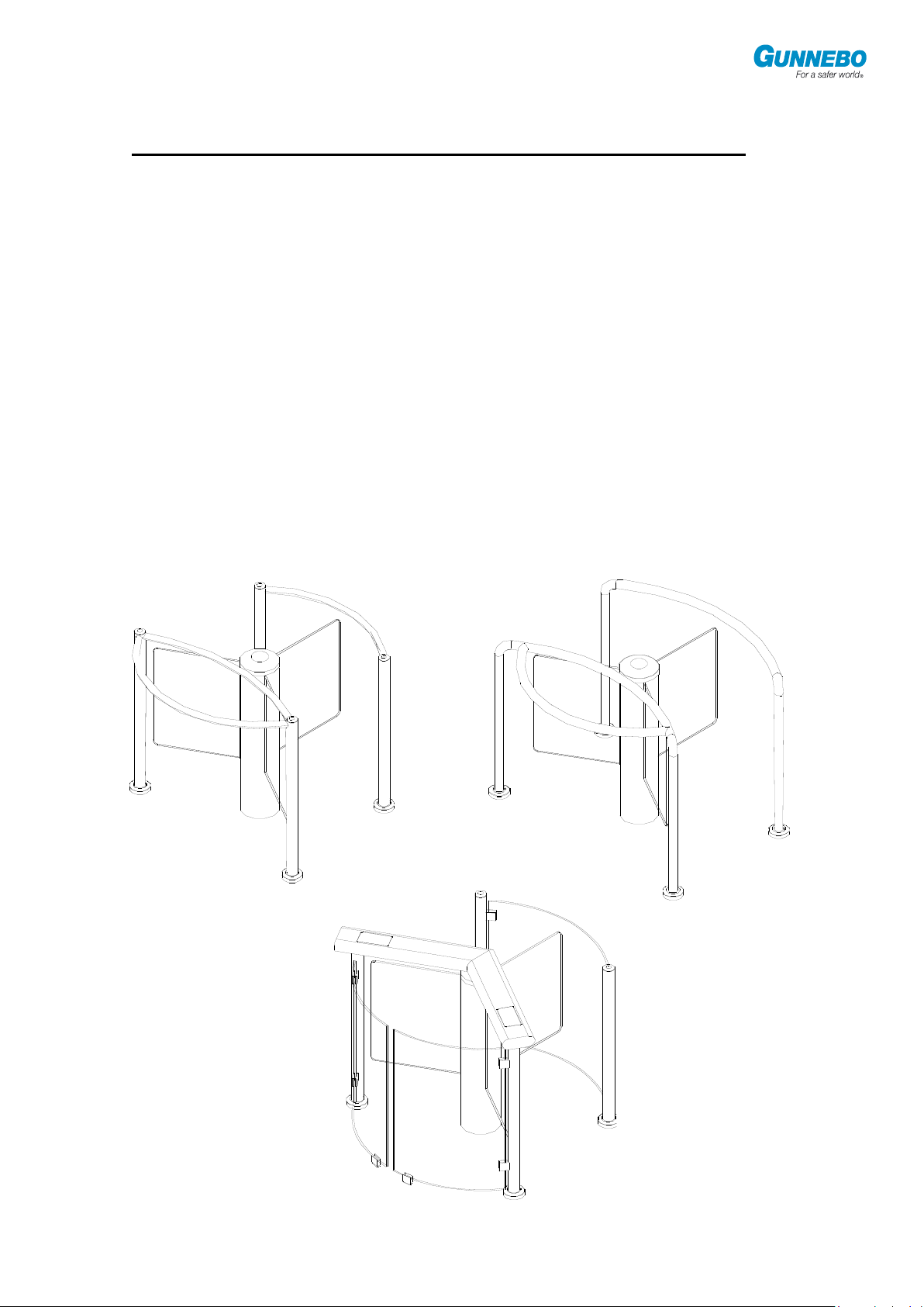
Type "A" Casework
Type "B" Casework
Type “C” Casework
Section 2 Product Description
Product Description
The Gunnebo GlasStile GSR is a revolving entrance gate with glazed panels. The GlasStile
GSR rotates clockwise or counter-clockwise 120 before being locked by an electro-magnetic
brake. The GlasStile GSR is activated in each direction by impulses to the driving electronics
unit from the reception or impulse unit (e.g. card reader or pushbutton).
Any impulse unit with a dry contact closing for between 0.5 - 1.0 seconds can be connected to
GlasStile GSR. Acknowledgement output pulse of completed rotations is given before and after
each rotation is completed. Optional status lights can show the status of the gate.
The speed, time delay, drive mode and individual setting of the panel‟s home positions can be
altered using an optional Hand Programming Unit. In the event of a power failure the
programmable functions are stored in a non-volatile memory.
The drive electronics are mounted on a printed circuit board that has connection points for
power, motor, brake, sensors, impulse units and status lights.
A 24V DC motor with gearbox drives the gate. An encoder is connected to the outgoing shaft
by a gear belt. The encoder‟s function is to monitor the position of the gate.
.............................
CCEC/ OM Manual GlasStile GSR 1.6 EN 07.2009

10
Casework
Size
Casework
Type
Height
mm
Depth
mm
Width
mm
1350
A
1050
1189
1387
1350
B
1050
1350
1350
1350
C
1076
1350
1350
Technical Specification
Unit Dimensions Column Height: 1000mm
Column Diameter: 220mm
Note: Casework is also available to special order in size 1500.
Drive 24V DC Motor and gearing
Orientation Vertical
Materials Cladding - Stainless Steel Grade 304
Panels -Toughened Glass
Power Failure Gate Rotate freely with any power loss or emergency signal
Power Supply Voltage: 110/230 VAC 50/60Hz
Power rating: 250 W, fuse 1.0 A
Note - Class C mains circuit breaker is required.
Other dimensions and materials are available upon request to Gunnebo.
.............................
CCEC/ OM Manual GlasStile GSR 1.6 EN 07.2009
11
Section 3 Instructions for Use
Instructions for Use
Starting the GlasStile
When power is switched on, the unit automatically searches for its internal zero position, moving
at a lower speed than normal. Once it has reached the blocking panel, it then automatically
moves to its programmed home position. The first time the gate is powered up it will move to its
default home position.
When the internal zero and home positions are being sought, the alarm output flashes slowly.
When searching has been completed the brake engages and the gate closed output switches.
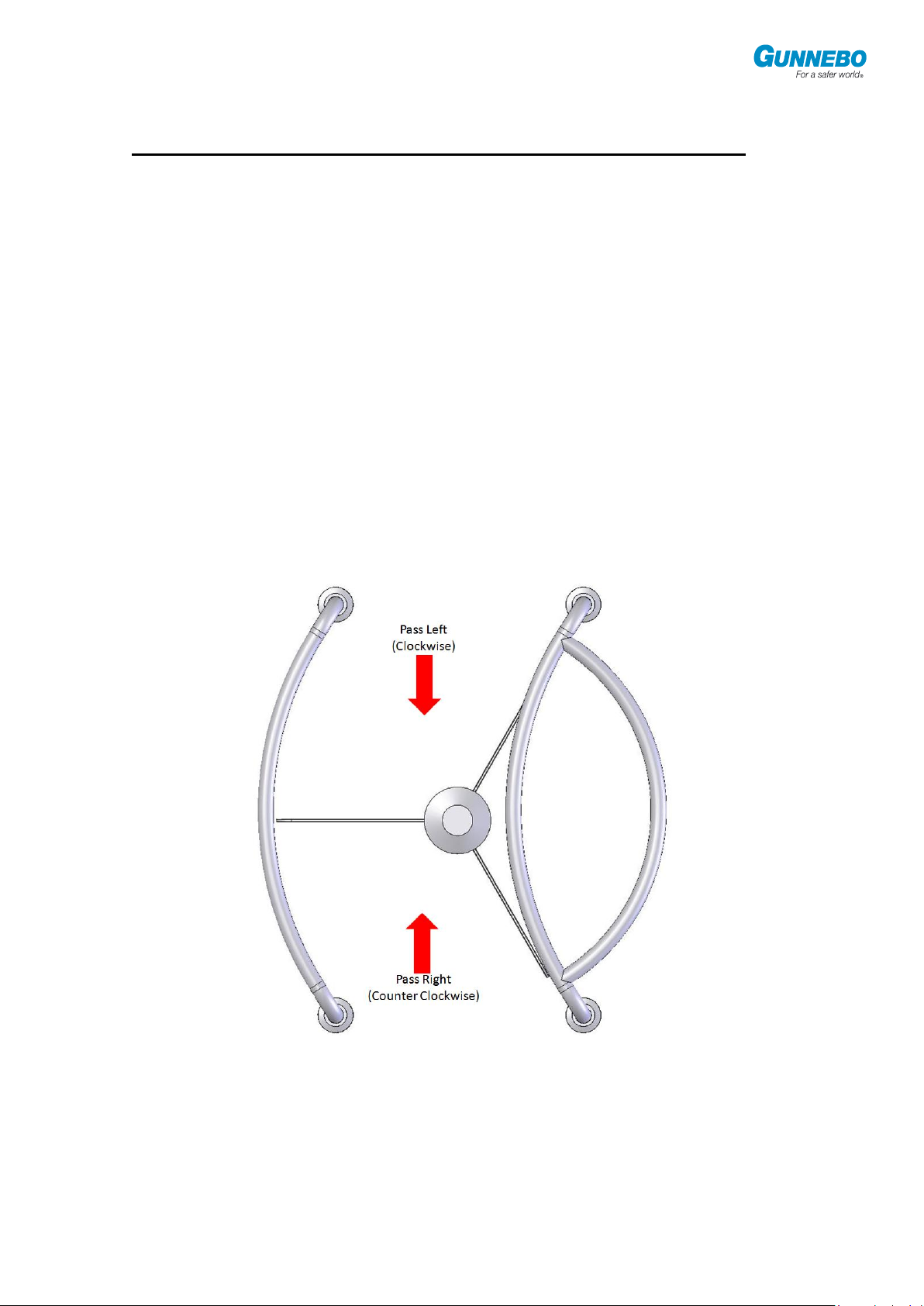
Reception Control Pass Left / Pass Right
There are two reception inputs, one each for PASS LEFT and PASS RIGHT directions.
The GlasStile GSR is passable for as long as the contact remains closed. On contact opening
the gate returns to its home position, where the electro-mechanical brake locks the wing back in
the barrier position.
No intrinsic acknowledgement of the rotation is given. The closed gate lamp illuminates and the
Status lights change from green to red.
.............................
CCEC/ OM Manual GlasStile GSR 1.6 EN 07.2009

12
Operating Modes
Card Reader Control - Push to Go
When a signal is applied to one of the two card reader inputs the unit releases the brake and
switches the gate closed output. Passage can now occur within the selected time, if no passage
is started within this time the GlasStile GSR will lock and a new impulse must be given.
The GlasStile GSR starts to rotate in the selected direction once the panel is moved from its
home position. The GlasStile GSR has acknowledgement outputs that are used when
interfacing with card reader systems. These relay contacts are, by nature, open circuit. They
can be programmed via the Hand Programmer to occur during or after a passage.
When rotation has completed and the gate is locked, the closed gate lamp comes on.
If Acknowledgement A (after rotation) is selected from the programming options, once the
rotation is completed another signal may be given from the impulse unit.
If Acknowledgement D (during rotation) is selected from the programming options then signals
may be given to the unit during a rotation, a maximum of five of these signals can be stacked.
Reset
The alarm period lasts for a period of 20 seconds, the unit‟s blocking panel will then return to the
correct position and normal operation is commenced.
Unauthorised passage
When the gate is locked, the electro-magnetic brake is activated on full power for 0.5 second.
The power is then reduced to a steady rate. This is to reduce the risk of heat build up in the
brake.
When unauthorised passage through the GlasStile GSR is attempted the braking power is less
than 240Nm, but when the lock is disturbed, the brake moves from its steady power rate to
maximum power for 5 minutes before returning to the steady rate.
Blocking or forcing GlasStile GSR during rotation
If the GlasStile GSR is blocked completely during operation for more than 10 seconds, the unit
will go into alarm mode and then commence the reset cycle detailed above.
The maximum force exerted by a unit at its highest speed during opening or closing is
45.6 Newton‟s.
The maximum force needed to break the force of the break when it is locked is 312.8
Newton‟s.
Power Failure
In the event of power failure, the brake will release & the gate will rotate freely. When the power
returns the gate searches first for its internal zero position and then for the home position similar
to when the GlasStile GSR is first started.
Fire Alarm
The GlasStile GSR has a facility for an external fire alarm input. The fire alarm output should be
a normally closed voltage free (0V) pair. When this pair is open the unit will freewheel in both
directions, this continues until the input is re-closed.
.............................
CCEC/ OM Manual GlasStile GSR 1.6 EN 07.2009

13
Section 4 Technical Information
Technical Information
The central column stands totally independent of the surrounding framework, housing the drive
motor, gearbox and electronics. All electronics and mechanical components are housed in the
centre column.
Toughened transparent glass panels are at 120O intervals.
The unit is supplied to integrate fully with all proprietary card reader systems, with a variety of
outputs and inputs, i.e. passage confirmed for updating anti-passback systems, inhibits, fire
alarm.
All that is required is a GO signal of duration between 0.5 and 1 second from the access control
system (voltage-free contact, normally open).
Material Finishes
Alternative materials, such as polished or grained stainless steel, brass or painted finishes can
be supplied to special order. Handrails can be supplied made from various materials, e.g. metal
or wood, please consult Gunnebo for further information.
Standard finish is cladding of brushed stainless steel with gate panels of 10mm transparent
toughened glass.
Flexibility of Design
Integrated design makes installation simple with a minimum of intrusion on the existing
environment.
This concept allows architects and designers the ability to design a security system that fits their
requirements for any situation. The GlasStile GSR is often installed with the addition of a
GlasStile GSS to provide disabled access.
.............................
CCEC/ OM Manual GlasStile GSR 1.6 EN 07.2009
 Loading...