

Gunnebo BLP User Manual
Ball bearing Lifting Point
(BLP)
EN User Manual
DE Montage- und Bedienungs hinweise
ES Guía del usuario
FR Manuel de l’utilisateur
IT Guida utente
SV Användarmanual
Z769449 Rev P10

User´s Guide ............................................................. 3
Bedienungsanweisung ............................................. 8
Guía del usuario ..................................................... 13
Manuel de l’utilisateur ............................................ 18
Guida utente .......................................................... 23
Användarmanual..................................................... 28

User Manual
General Information
Reference should be made to relevant standards and other statutory
regulations. Inspections must be carried out only by people who possess
sufficient knowledge.
Before installation and before every use, visually inspect the lifting points,
paying particular attention to any evidence of corrosion, wear, weld cracks
or deformations. Please ensure compatibility of bolt thread and tapped
hole.
The material construction, to which the lifting point will be attached,
should be of adequate strength to withstand forces during lifting without
deformation.
Minimum thread depth requirements (d refers to bolt diameter):
• 1 x d for steel (Yield limit >200MPa).
• 1.25 x d for cast iron (Yield limit >200MPa).
• 2.5 x d for aluminum alloy.
• For other metal alloys and other base materials, please consult your
Gunnebo Industries distributor.
General assembly instructions:
• The surface facing around the thread hole shall be flat (plane), clear of
paint and dirt, and smooth to ensure a perfect flush contact with the
shoulder surface of the lifting point.
Conditions for symmetric lifts with 1, 2, 3 or 4 legs
• For three and four leg lifts, the lifting points should be arranged
symmetrically around the center of gravity in the same plane if
possible.
• Load Symmetry: The working load limit for Gunnebo Industries lifting
points is based on symmetrical loading.
• The lifting points must be positioned on the load in such a way that
movement is avoided during lifting.
• For single leg lifts, the lifting point should be vertically above the
center of gravity of the load.
• For two leg lifts, the lifting points must be equidistant to or above the
center of gravity of the load.
Conditions for asymmetric lifts with 2, 3 or 4 legs
For unequally loaded chain legs we recommend that the Working Load
Limit is determined as follows:
• 2-leg slings calculated as the corresponding 1-leg sling.
• 3 and 4-leg slings calculated as the corresponding 1-leg sling*.
* (If 2 legs with full certainty are carrying the major part of the load, the
working load limit can be calculated as for the corresponding 2-leg sling.)
3

Extreme temperature conditions
Temperature (ºC) Reduction of Working Load Limit
-40º to 200ºC No reduction
Temperatures below -40° or
above 200º C not allowed
Surface treatment
Note! Hot-dip galvanising or plating is not allowed without control from
the manufacturer.
Severe environments
Lifting points must not be used in alkaline (> pH10) or acidic conditions
(< pH6).
Regular comprehensive examinations must be carried out when used
in severe or corrosive environments. In uncertain situations consult your
Gunnebo Industries distributor.
Protect yourself and others
• Before each use, the lifting point should be checked for obvious
damage or deterioration.
• Know the weight of the load and its centre of gravity.
• Ensure the load is ready to move and that no obstacles will obstruct the
lifting.
• Check the conformity of the load with the Working Load Limit.
• Prepare the landing site.
• Never overload and avoid shock loading.
• Never use an improper configuration.
• Never use a worn or damaged lifting point.
• Do not ever ride on the load.
• Do not ever walk or stand under the suspended load.
• Take into consideration that the load may swing or rotate.
• Watch your feet and fingers while loading/unloading.
4
Specific Information
• Make sure BLP can rotate 360° and articulate 180° without interfearing
with other parts.
• BLP should be tightened to torque according to the relevant table (+/10%). In case of turning movements the recommended torques must
be checked regularly.
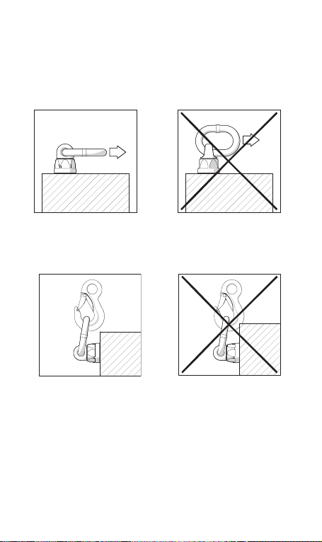
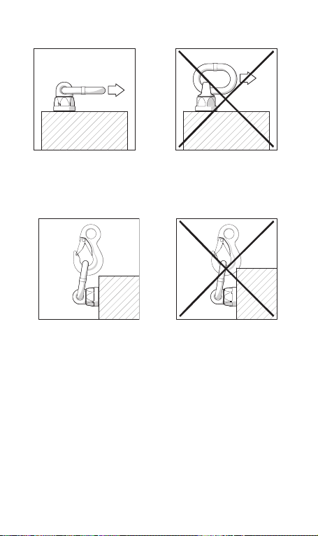
• Adjust to the direction of the pull before attaching to the lifting means.
• All fittings connected to the BLP should be free moving. When
connecting and disconnecting the lifting means (wire ropes, chain
slings, round slings), pinches and impacts should be avoided. Damage
to lifting components caused by sharp corners should also be avoided.
• To prevent unintended dismounting through shock loading, rotation
or vibration, thread-locking fluid such as Loctite (depending on the
application, please refer to the manufacturer’s instruction) should be
used to secure the bolt.
• Do not fit with larger hook than BLP can accomodate.
After fitting, an inspection for suitability should be carried out by a person
with sufficient knowledge at least annually or more frequently if conditions
merit. Inspections shall also be carried out after any damage or special
occurances.
5

Inspection criteria
• Ensure compatibility of bolt thread and tapped hole - control of the
torque.
• The lifting point should be complete.
• The working load limit and manufacturers stamp should be clearly visible.
• Check for deformation of the component parts such as body, load ring
and bolt.
• Check for mechanical damage, such as notches, particularly in high
stress areas.
• Wear should be no more than 10% of cross sectional diameter. For
measurements of the BLP please see the Gunnebo Industries product
catalogue.
• Evidence of corrosion.
• Evidence of cracks.
• Damage to the bolt, nut and/or thread.
• The body of the BLP must be free to rotate.
• Rotate the BLP in both directions while loaded by approximately 5% of
max working load limit according to table. The BLP should rotate easily,
if not, remove for service.
• Due to the ball bearing carriage way, proof loading is not suitable for
the BLP. Testing should be MPI (Magnetic Particle Inspection) and visual
check.
• The maximum gap between upper and lower part of
the BLP must not exceed 2,5 mm.
• For the user it is not recommended to disassemble the
ball bearing housing.
S
• For dimensions, please refer to Gunnebo´s product catalogue.
This safety instruction/declaration of the manufacturer must be kept on
file for the lifetime of the product.
Please inspect all lifting points prior to use. Damage, incorrect
assembly or improper use may result in serious injuries and/or
EC-Declaration of the manufacturer
According to the Machinery Directive 2006/42/EC, annex II B.
We hereby declare that the design and construction of the equipment
detailed within this document, adheres to the appropriate level of
health and safety of the corresponding EC regulation.
Any un-authorized modification and/or any incorrect use of the
equipment not adhered to within these user instructions waivers this
declaration invalid.
Failure to carry out the recommended maintenance and testing waivers
this declaration invalid.
ATTENTION:
material damage.
6
number
Spanner size Article
torque
Z102008
Z102108
36 mm
1 1/2” UNC
10 Nm
7Ft.Lbs
0.45 T
0.45 T
0.6 T
0.6 T
0.4 T
0.4 T
0.3 T
0.3 T
0.4 T
0.4 T
0.6 T
0.6 T
1.2 T
1.2 T
0.3 T
0.3 T
0.6 T
0.6 T
Z102010
Z102110
36 mm
1 1/2” UNC
15 Nm
11Ft.Lbs
0.75 T
0.60 T
1.3 T
0.8 T
0.7 T
0.5 T
0.5 T
0.4 T
0.7 T
0.5 T
1.0 T
0.8 T
2.0 T
1.6 T
0.5 T
0.4 T
1.0 T
0.8 T
Z102012
Z102112
36 mm
1 1/2” UNC
27 Nm
20Ft.Lbs
1.1 T
1.1 T
1.5 T
1.5 T
1.1 T
1.0 T
0.75 T
0.75 T
1.1 T
1.0 T
1.5 T
1.5 T
3.0 T
3.0 T
0.75 T
0.75 T
1.5 T
1.5 T
Z102016
Z102116
36 mm
1 1/2” UNC
60 Nm
44Ft.Lbs
2.2 T
2.2 T
3.1 T
3.1 T
2.1 T
2.1 T
1.5 T
1.5 T
2.1 T
2.1 T
3.0 T
3.0 T
6.0 T
6.0 T
1.5 T
1.5 T
3.0 T
3.0 T
Z102020
Z102120
50 mm
2” UNC
90 Nm
66Ft.Lbs
3.7 T
3.3 T
5.2 T
4.7 T
3.5 T
3.1 T
2.5 T
2.25 T
3.5 T
3.1 T
5.0 T
4.5 T
10.0 T
9.00 T
2.5 T
2.25 T
5.0 T
4.5 T
Z102121
Z102024
50 mm
2” UNC
135 Nm
66Ft.Lbs
4.5 T
6.0 T
6.3 T
8.4 T
4.2 T
5.6 T
3.0 T
4.0 T
4.2 T
5.6 T
6.0 T
8.0 T
14.0 T
12.00 T
3.0 T
4.0 T
6.0 T
7.0 T
Z102124
Z102030
65 mm
2” UNC
270 Nm
100Ft.Lbs
6.0 T
9.0 T
8.4 T
12.6 T
5.6 T
8.4 T
4.0 T
6.0 T
5.6 T
8.4 T
8.0 T
12.0 T
14.0 T
24.0 T
4.0 T
6.0 T
7.0 T
12.0 T
Z102130
Z102036
Z102136
65 mm
2 5/8” UNC
2 5/8” UNC
320 Nm
200Ft.Lbs
236Ft.Lbs
9.0 T
12.0 T
12.0 T
12.6 T
16.8 T
16.8 T
8.4 T
11.2 T
11.2 T
6.0 T
8.0 T
8.0 T
8.4 T
11.2 T
11.2 T
12.0 T
16.0 T
16.0 T
24.0 T
28.0 T
28.0 T
6.0 T
8.0 T
8.0 T
12.0 T
14.0 T
14.0 T
Z102042
Z102142
85 mm
3 1/8” UNC
600 Nm
440Ft.Lbs
15.0 T
15.0 T
21.0 T
21.0 T
14.0 T
14.0 T
10.0 T
10.0 T
14.0 T
14.0 T
20.0 T
20.0 T
32.0 T
32.0 T
10.0 T
10.0 T
16.0 T
16.0 T
Z102048
Z102148
85 mm
3 1/8” UNC
800 Nm
590Ft.Lbs
19.5 T
19.5 T
27.3 T
27.3 T
18.2 T
18.2 T
13.0 T
13.0 T
18.2 T
18.2 T
26.0 T
26.0 T
36.0 T
36.0 T
13.0 T
13.0 T
18.0 T
18.0 T
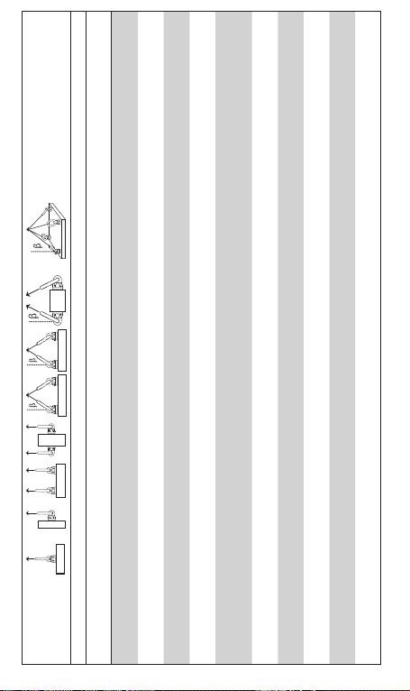
Symmetric Load
(Tonne)
No. of legs 1 1 2 2 2 symmetric 3 & 4 symmetric
Angle ß 0° * 90° 0° 90° 0-45° 45-60° 0-45° 0-45° 45-60° Tightening
BLP -M8x1.25
BLP 5/16”-18 UNC
Technical specifications
BLP -M10x1.5
BLP 3/8”-16 UNC
BLP -M12x1.75
BLP 1/2”-13 UNC
BLP -M16x2
BLP 5/8”-11 UNC
7
BLP -M20x2.5
BLP 3/4”-10 UNC
BLP 7/8”-9 UNC
BLP -M24x3
BLP 1”-8 UNC
BLP -M30x3.5
BLP 1 1/4”-7 UNC
BLP -M36x4
BLP 1 1/2”-6 UNC
BLP -M42x4.5
BLP 1 3/4”-5 UNC
BLP -M48x5
BLP 2”-4.5 UNC
Safety factor 4:1
* provided only axial loading takes place. ie no bending force applied in the direction of the thread.

Montage- und Bedienungshinweise
Allgemeine Informationen
Es wird auf allgemeine Standards und aktuelle gesetzliche Vorschriften
verwiesen. Die Montage und Inspektion darf nur von Personen ausgeführt
werden, die über entsprechende Sach- kenntnisse verfügen.
Vor der Montage und vor jeder Anwendung ist eine visuelle Kontrolle der
Anschlagpunkte durchführen. Hierbei ist besonders auf Anzeichen von
Korrosion, Verschleiß, evtl. Rissen an Schweißnähten sowie Verformungen
Bauteil und am Transportgut zu achten. Stellen sie sicher, dass das
Schraubengewinde des Anschlagpunktes und die Gewindebohrung
aufeinander abgestimmt sind.
Die konstruktive Ausführung, an die der Anschlagpunkt angebracht werden
solll , muss eine angemessene Materialstärke aufweisen, um den Kräften
während des Hubvorgangs ohne Verformung standzuhalten.
Erforderliche Mindestgewindetiefe (d bezieht sich auf den
Schraubendurchmesser ):
• 1 x d für Stahl (Dehngrenze >200MPa).
• 1,25 x d für Gusseisen (Dehngrenze >200MPa).
• 2,5 x d für Aluminiumlegierung.
• Für andere Metalllegierungen und andere Basismaterialien wenden Sie
sich bitte an Ihren Gunnebo Industries-Händler.
Allgemeine Montageanweisungen:
• Die Oberfläche um die Gewindebohrung herum muss eben (glatt ) und
frei von Farbe und Schmutz sein, um einen optimal bündigen Kontakt
mit der Auflagfläche des Anschlagpunktes zu gewährleisten.
Bedingungen für symmetrische Lastgehänge mit 1, 2, 3 oder 4 Strängen
• Für die Lastaufnahme mit 3-- oder 4-strang- Anschlagmitteln
sollten die Anschlagpunkte nach Möglichkeit symmetrisch um den
Massenschwerpunkt und in derselben Ebene angeordnet sein
• Lastsymmetrie: Die maximale Tragfähigkeit für Anschlagpunkte von
der Gunnebo Industries AB basiert auf einer symmetrischen Belastung.
• Die Anschlagpunkte müssen so an der Last angebracht werden, dass
Schwerpunktverlagerungen während des Hebenvorgans vermieden
werden.
• Beim Einsatz von 1-strang Anschschlagmitteln , sollte der
Anschlagpunkt senkrecht über dem Massenschwerpunkt der Last
angebracht werden.
• Für 2-strängige Anschlagmittel müssen die Anschlagpunkte im selben
Abstand zum, oder über dem Massenmittelpunkt der Last angebracht
werden.
Bedingungen für asymmetrische Anschlagmittel mit 2, 3 oder 4 Strängen
Für ungleich belastete Kettenstränge empfehlen wir, die maximale
Tragfähigkeit wie folgt zu bestimmen:
8

• 2-strängige Anschlagmittel werden wie 1-strängigeberechnet.
• 3- und 4-strängige Anschlagmittel werden wie die 2-strängige berechnet*.
* (Nehmen 2 Stränge mit hundertprozentiger Sicherheit den Großteil
der Last auf, kann die maximale Tragfähigkeit wie für das entsprechende
2-strängige Anschlagmittel e berechnet werden.)
Temperaturbedingungen
Bei Temperatur (ºC) Verringerung der maximalen Tragfähigkeit
-40º bis 200ºC Keine Verringerung
Achtung: Anwendung bei Temperaturen unter
-40 ° C oder über 200º sind nicht zulässig!
Oberflächenbehandlung
Achtung Wichtig! Feuerverzinkung oder -beschichtung ist nicht ohne
vorherige Genehmigung des Herstellers erlaubt.
Besondere Einsatzbedingungen
Anschlagpunkte dürfen nicht in basischer (> pH10) oder saurer Umgebung
(< pH6) verwendet werden.
Bei Anwendung in beanspruchenden oder korrosiven Umgebungen müssen
regelmäßige, gründliche Untersuchungen erfolgen. In Zweifelsfällen
wenden Sie sich bitte an Ihren Gunnebo Industries-Händler.
Schützen Sie sich und andere
• Vor jedem Einsatz sollte der Anschlagpunkt auf sichtbare Schäden oder
sichtbaren Verschleiß untersucht werden.
• Ermitteln Sie das Gewicht der Last und deren Schwerpunkt.
• Stellen Sie sicher, dass die Last anschlagbereit ist und keine
Hindernisse den Hubvorgang behindern.
• Überprüfen Sie, dass die Last mit der maximalen Tragfähigkeit übereinstimmt.
• Bereiten Sie die Abladestelle vor.
• Überlastung und Stoßbelastung sind unter allen Umständen vermeiden.
• Unter keinen Umständen eine ungeeignete Konfiguration verwenden.
• Unter keinen Umständen einen verschlissenen oder beschädigten
Anschlagpunkt verwenden.
• Unter keinen Umständen auf der Last mitfahren.
• Niemals unter hängenden Lasten aufhalten.
• Denken Sie daran, dass die Last beim Anheben kippen, schwingen
oder sich drehen kann.
• Achten Sie beim Beladen/Entladen auf Ihre Füße und Hände/Finger.
Besondere Informationen
•
Es muß sichergestellt sein, daß sich der BLP um 360° drehen und um 180°
geschwenkt werden kann, ohne das andere Teile beeinflusst werden
• Der Anschlagpunkt muss mit dem Anzugsmoment laut der
entsprechenden Tabelle angezogen sein (+/- 10%). Bei Drehbewegungen
müssen die empfohlenen Anzugmomente regelmäßig kontrolliert werden.
9
.
•
Vor dem Anschlagen an die Anschlagmittel Lastöse der Belastungsrichtung
anpassen.
• Sämtliche an den Anschlagpunkt angebrachten Befestigungen
müssen sich frei bewegen können. Beim Befestigen und Lösen
der Anschlagmittel (Stahlseile, Kettenschlingen, Rundschlingen)
sind Einschnürungen und Stöße zu vermeiden. Auch Schäden an
Anschlagmitteln aufgrund scharfer Kanten sind zu vermeiden.
• Um unbeabsichtigte Demontage durch Stoßbelastung, Drehung
oder Schwingung zu vermeiden, kann zur Sicherung der Schraube
Schraubensicherungslack wie Loctite verwendet werden (je nach
Anwendung, bitte lesen Sie die Anweisung des Herstellers).
• Beim Haken dürfen keine größeren als die zum BLP passenden Haken
verwendet werden.
Im Einsatz sollte der Anschlapunkt ( e) von einer Person mit entsprechenden
Kenntnissen mindestens einmal jährlich oder häufiger, sofern die
Bedingungen dies erfordern, überprüft werden. Auch nach einem evtl. j
Schadensfall oder besonderen Zwischenfällen muss eine Prüfung stattfinden.
Prüfungskriterien
• Stellen Sie, die korrekte Größe, Qualität und Länge von Schraube und
Mutter sicher.
• Stelle Sie sicher, dass Schraubengewinde und Gewindebohrung
aufeinander abgestimmt sind – kontrollieren Sie das Anzugsmoment.
• Der Anschlagpunkt muss vollständig sein.
10
 Loading...