

Gundlach 710 Owner's Manual
Owner’s Manual
Before operating the unit, please read this
manual thoroughly, and retain it for future
reference.
English Espanol
~
No. 710 7" Tile Saw
211 North 21st Street • P.O. Box 544
Belleville, IL 62222 • U.S.A.
Tel: 618 233-1781 Fax: 618 233-3636
www.benojgundlachco.com

Saw Exploded View...............................
Replacement Parts List...........................
Features........................................
Safety Precautions................................
Unpacking, Assembly & Setup......................
Stand Assembly..................................
Blade Installation.................................
Bearing Housing Installation........................
Water Pump Installation............................
Water Pump Maintenance..........................
Water Pump Safety Precautions.....................
Using the Cutting Table............................
Cutting Depth....................................
Belt Replacement.................................
Electrical Motor Specifications......................
Optional Accessories.............................
Do's & Don'ts for Diamond Blades....................
Saw Maintenance................................
Troubleshooting.............................
Notes..........................................
Warranty.......................................
Warning........................................
3
4,5
7
7
9
11
12
13
15
15
15
17
19
19
21
23
25
27
29,31,33
35
37
38
3
4,5
7
8
10
11
12
14
16
16
16
18
18
20
22
24
26
28
30,32,34
36
37
38
TABLE OF CONTENTS
INDICE
Diagrama de la Sierra.............................
Lista de Partes de Repuesto.......................
Caracteristicas...................................
Precauciones y Seguridad..........................
Desempaque y Ensamble..........................
Instalacion de la base.............................
Instalacion de la Cuchilla..........................
Installation del Alojamiento del Cojinete..............
Instalacion de la Bomba de Aqua...................
Mantenimiento la Bomba de Agua..................
Cuidados con Bomba del Agua.....................
Profunidad de Corte..............................
Remplazamiento de la Banda......................
Accesorios Opcionales............................
Como Usar las Cuchillas..........................
.
Uso de la Base de Corte..........................
Especificaciones electricas del Motor..................
Mantenimiento de la Sierra
........................
Problemas y Soluciones......................
Notas..........................................
Garantia.......................................
Precaucion.....................................

710 SAW EXPLODED VIEW
710 DIAGRAMA DE LA SIERRA
710 REPLACEMENT PARTS LIST
Lista de Partes de Repuesto
-3-
-4-
710
Accessories Included
(Accessorios Incluidos)
710
Accesso
ries Included
(Accessorios Incluidos)
PART NAME PART NUMBER
LCBH
Bearing Housing Package
(Paquete de Cojinete)
LCBH
Bearing Housing Package
(Paquete de Cojinete)
700-17
710-02
710-03
710-04
710-05
710-06
710-07
710-08
700-10
1000-13
710-11
710-12
G-100A4
100021
171016BJ
1000-12.1
710-18
0329SP
1000-49BJ
1000-12
700-20
700-22
1000-17
170030
700-24
700-34
1000-41
1000-35
884
1000-48
710-19
1
2
3
4
5
6
7
8
9
10
11
12
13
15
16
17
18
18.1
19
20
21
22
23
24
25
26
27
28
29
30
32
Power Cable/ Cable de Potencia
1 HP Brush Motor
Motor Shaft Pulley/ Polea del eje del motor
Motor Adjustment Clip/ Seguro de Ajuste del Motor
Mounting Plate/ Plato de Ensamble
Belt Guard Bracket/ Brazo de Montaje de la Cubierta de la Banda
Timing Belt/ Banda
Belt Guard/ Cubierta Protectora de la Banda
Belt Guard screws/ Tornillos de la Cubierta Protectora de Banda
Blade Shaft/ Eje Impulsor de Cuchilla
Blade Shaft Pulley/ Polea de Cuchilla
Sliding Rails (set of 2 )/ Rieles Deslizables (2)
Water Pump/ Bomba de Agua
Mounting Plate Adjustment Knob/
Perilla de Ajuste de la Placa de Montaje
Rear Post (Included in Metal Frame & Motor Support
Shaft)/ Poste Trasero (Incluye Estructura Metal y Soporte del
Motor
/ Baleros del Borde Exterior
Inner Flange Bearing
PolypropyleneWater Tray/ Bandeja o Deposito del Agua
Drain Plug/ Tapon de Plastico
Motor Protection Cover Shield/ Tornillos de Ensamble
Bearing Housing Lock Bolts and Nuts/ Tuercas y
Seguros del Alojamiento del Cojinete
Bearing Housing Secure Brackets (set of 2)/
Alojamiento del Cojinete Braquetas Aseguradora (2)
Pulley Bearing / Baleros de la Polea
Inner Flange/ Interior el reten de la Cuchilla
Outer Flange/ El reten Exterior de la Cuchilla
Blade Lock Nut/ Tuerca Aseguradora de la Cuchilla
Cutting Table Position Bracket/
Posicion de Braqueta para la Mesa de Cortar
U-Shape Ball Bearing Rollers (set of 2)/
Rueda Acanalada de Cojinete
Miter Block (metal)/ Bloque de Mitra (metal)
Universal Wrench/ Multiple Llave
45º/90° Rip Guide/ 45º/90° Guia de Corta Angular
Universal Tile Guide/ Guia Maestra
49
-5-
-6-
REPLACEMENT PARTS LIST continue.
ADDITIONAL HELP
Please call us if for any reason you are having difficulty that
cannot be resolved with the troubleshooting guide included in
the back of this manual. We would like to help.
To better service our customers as expediently as possible,
please make sure that you have the manufacturing serial
number available before contacting us.
PART NAME PART NUMBER
710-33
1000-03
710-35
1000-20
1000-45N
100018
700-02BJ
1000-25
170026
170027
700-13
710-44BJ
700-37
710-46
710-47
171027
33
34
35
36
37
38
39
40
41
42
43
44
45
46
47
49
Power Switch Housing(w/ Power Switch,Circuit Breaker, &
Power Cable)/ Alojamiento del Interruptor de Encendido
Power Toggle Switch / Interruptor de Encendido
Circuit Breaker/ Conector del Circuito
Water Flow “T” Adapter/ Adaptador “T” del Flujo de Agua
Water Flow “L” Adapter/ Adaptor de agua “L”
Blade Guard Adjustment Knob/
Perilla de Ajuste del Protector de la Cuchilla
Blade Guard/ Protector de la Cuchilla
Teflon Angle Bar Rollers (set of 2)/ Barras Angular de Teflon
de Rodaje (2)
Cutting Table (Includes Wheels & Ruler Guide)/ Base de
Corta (Incluye Ruedas y Guia de Reglas)
Ruler Guide/ Guia Graduada
Saw Stand with Workbench/ Mesa Dobladiza con Banca de
Trabajo
Complete LCBH(Liquid Cooling Bearing Housing)/
Alojamiento del Cojinete Completo
Rubber Splash Guard/ Protector de Salpicadura de Gamal
Carbon Brushes (set of 2)/ Cepillo del Carbon (2)
Brush Cap/ Tapa del Cepillo
Rear Post Cover/ Cubierta del Poste Posterior
Note: If there is any part that is needed and has not been included in this parts list,
please contact our customer service 618 233-1781
CUSTOMER SERVICE:
211 North 21st Street • P.O. Box 544
Belleville, IL 62222 • U.S.A.
Tel: 618 233-1781 Fax: 618 233-3636
www.benojgundlachco.com
Give us a call at
618 233-1781
-7-
-8-
• Never use the machine improperly or work in an unsafe manner.
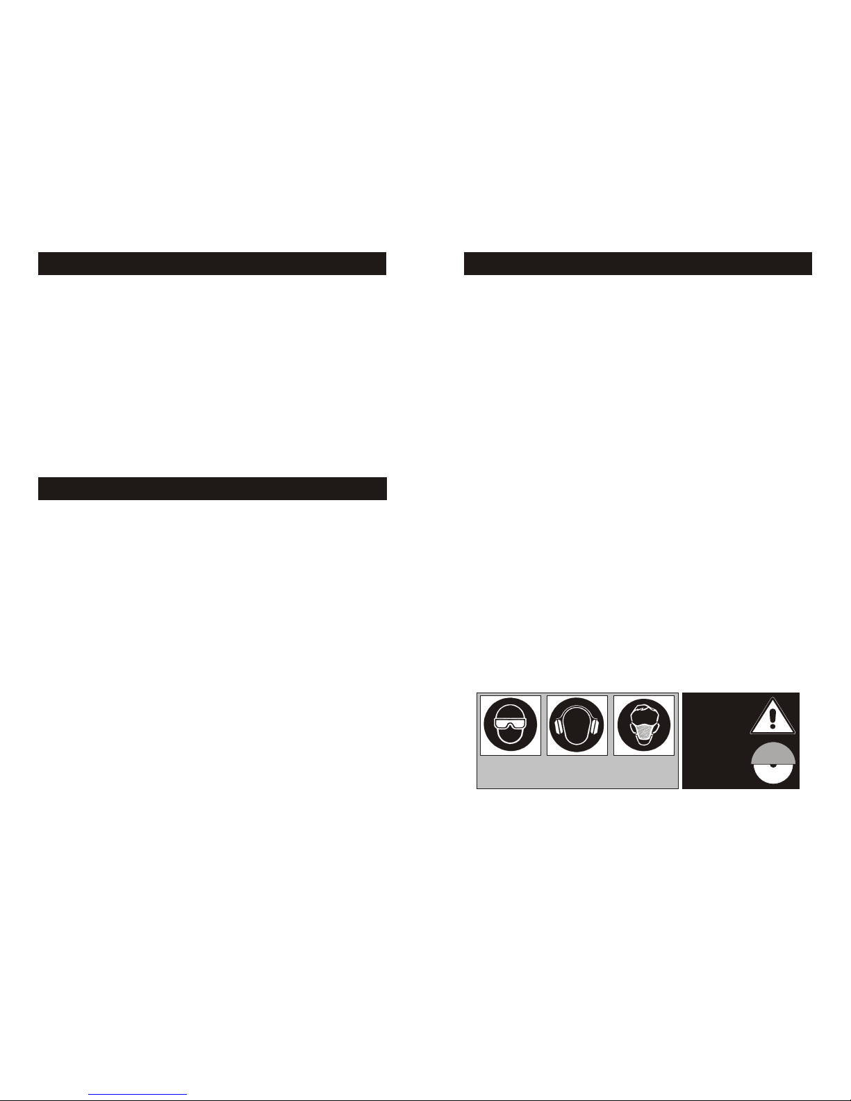
• Always wear safety goggles, dust mask, and ear protection while
operating the saw (to comply with ANSI-Z87.1).
• Always remain alert when the saw is in use. Failure to pay attention on
the operator’s part may lead to serious injury.
• Before you start working, familiarize yourself with the work site and its
surroundings. Take notice of circumstances which may impede working
or traffic, observe soil conditions (good bearing or not), and take
measures to ensure safety (i.e. the shielding of roadworks from public
traffic).
• Take measures to ensure that the machine is in a safe and trouble-free
condition prior to usage. Use the machine only when all protective
devices (i.e. guards, noise absorbers, emergency-off devices) are
operating in the intended locations.
• A visual check of the machine must be made at least once a shift to
ensure that visible damages or faults are recognized. Any changes
(including changes in the performance or behavior of the machine)
must be reported to the supervisor. If necessary, stop the machine at
once and secure it.
• In the case of a malfunction, stop the machine immediately and secure
it. Fix the problem as soon as possible.
• For starting and stopping the machine follow the operating instruction
steps and observe any indicator lights.
• Before switching the machine on make sure that the activated machine
will be of no danger to anyone.
SAFETY PRECAUTIONS
• A Powerful 1 HP brush motor makes cutting easier and quicker.
• The Automatic Thermal Overload Protection system protects your saw from
power surges and overheating.
• The high fiber plastic water tray withstands even the toughest punishment yet it
is extremely easy to remove and install.
• The saw is encased in a sturdy, durable steel frame, optional equipped with
folding stands with work bench for easier operation.
• Adjustable guide rails permit the user to align the saw during installation.
• The cutting alignment will not be affected by any water tray maintenance.
• The cutting table can be secured in place by tightening the knob screw on the
L-shaped transport retention plate.
• The cutting rip guide is designed for both 90º square cutting and 45º angle
cutting.
• The No. 710 blade capacity is 6"~7" which provides a variety of blade usage.
• Straight cuts can extend out to 17" in length and diagonal cut up to 12" in
length.
FEATURES
PRECAUCIONES Y SEGURIDAD
• Nunca use la maquina de una manera impropia o trabaje de una
manera insegura.
• Siempre use gafas de seguridad, mascarilla para el polvo, y proteccion
para los oidos cuando se encuentre operando la sierra (cumpliendo con
ANSI-287.1).
• Permanezca siempre alerta cuando la sierra este en uso. La falta de
atencion por parte del operador podria conducir a daños serios.
• Antes de empezar a trabajar, familiarizese usted mismo con el lugar de
trabajo y sus alrededores, tomando en cuenta las circunstancias que
pudieran impedir el trabajo o la circulacion libre. Observe la
condiciones del terreno (buen apoyo o no), y tome medidas que
garantizan la seguridad por ejemplo el correcto aislamiento de los
accesos al trabajo de la circulacion publica.
• Tomo medidas para garantizar que la maquina este en condiciones
seguras, y libre de problemas antes de usarla. Use la maquina
solamente cuando todos los dispositivos de proteccion esten operando
en la forma indicada, por ejemplo: cubiertas, silenciadores, y
dispositivos de desactivacion.
• Una revision visual debera hacerse al menos una vez cada turno para
asegurar que los daños visibles o fallas sean localizadas. Cualquier
cambio debera ser reportado al supervisor, incluyendo cambios en le
rendimiento o comportamiento de la maquina; si es necesario
apaguela y asegurela.
• En caso de malfuncionamiento apague la maquina inmediatamente y
asegurela. Arregle el problema lo mas pronto posible.
• Para prender y apagar la maquina siga las instrucciones de operacion, y
observe la luces indicadoras.
• Antes de encender la maquina este seguro de que la misma no sera de
ningun riesgo para alquien.
ALWAYS WEAR
SAFETY GEAR
USE
PROPERLY
GROUNDED
CIRCUIT
USE BLADE
GUARD
WHEN
OPERATING
SAW
-9-
-10-
Open the container, carefully lift the saw by the saw frame handles and
place it on a flat, level working area. Be certain that you have the following
items before you discard the container.
• Saw • Universal Wrench
• Polypropylene Water Tray • Water Pump
• 7" Saw Blade • Miter Block
• 45º / 90º Rip Guide • Owner's Manual
Proceed to the following section, to complete assembly of saw.
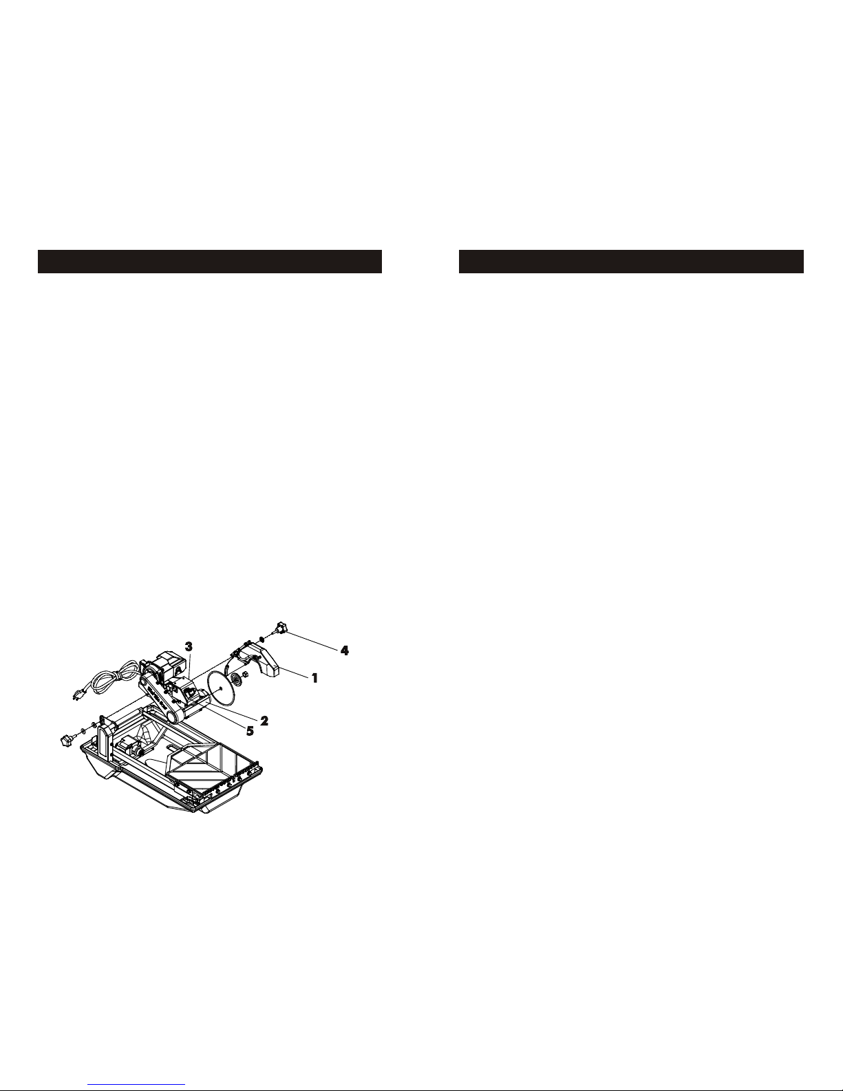
Blade Guard and Blade Assembly:
1. Remove the Blade Guard (1) and saw Blade package from the
accessory box.
2. Lift up the cutting head (2) from the insert style-foam that is designed
to re-enforce strength to the box.
3. Slide the cutting head through the rear support post’s shaft as shown in
the lower diagram and screw on the adjustment knob.
4. Slide the Blade Guard into the hex bolt (3) located at the rear of right
side of the Electrical Control Box (5) and fasten tightly using the knob
screw (4).
5. Place the 7" blade onto the shaft, make sure that the directional
arrow is pointing in the direction of the shaft rotation. Lift up the Blade
Guard, then fasten the blade tightly using the outer Flange and Lock
Nut.
UNPACKING, ASSEMBLY & SETUP
DESEMPAQUE Y ENSAMBLE
Abra el empaque cuidadosamenta y levante la sierra usando las asas del
armazon depositandola en terreno plano y nivelado en el area de trabajo.
Asegurese de que usted cuenta con los siguientes componentes antes de
desechar el empaque:
• Sierra • Llave Universal
• Deposito para el Agua de Polypropylene • Bomba de Agua
• 7" Cuchilla de la Sierra • Tapon de Drenado
• Bloque de Soporte para Cortes Diagonales • Manual de Propietario
Proceda con las siguientes secciones, para ensamblar el resto de la sierra.
Ensamble de protector de cuchilla y ensamble de cuchilla:
1. Remueva el protecor de la cuchilla (1) y la cuchilla (2) empacados en
la caja.
2. Use las asa de metal (3) para remover la maquina de la caja.
3. Deslize la cabeza cortadora en el poste de soporte como se ensena en
la parte baja del diagrama y apriete el tornillo de ajuste.
4. Deslize el protector de la cuchilla en el eje (4) localizado en la parte
trasera de la caja elctica (4) y apriete usando la perilla de ajuste (5).
5. Ponga la sierra de 7 pugadas el eje (6) asegurese que la flecha este
apuando en la direccion correcta de la rotacion del eje.Levante el
protector de la cuchilla, ponga la cuchilla apretandola usando el borde
exterior de la cuchilla (7) y asegurelo con la tuerra (8).
 Loading...