

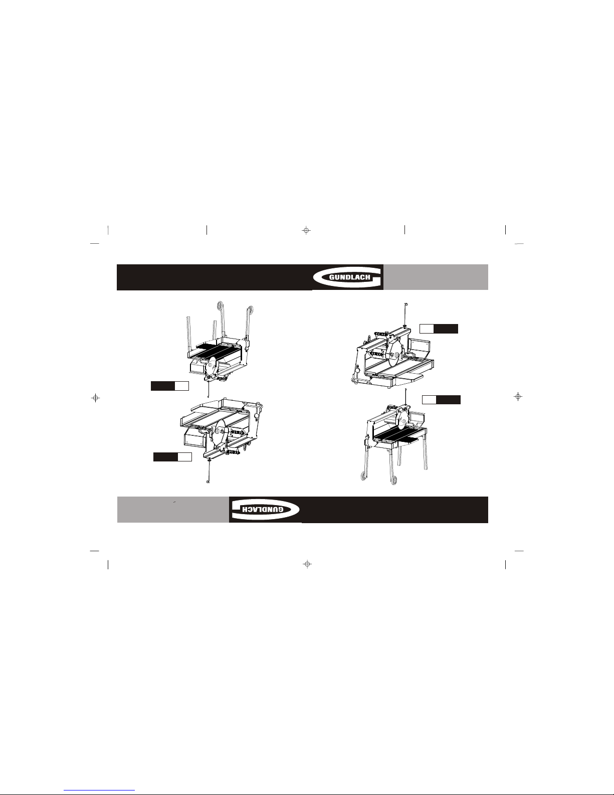
Gundlach 1027 Series, 1037 Series Owner's Manual
Manual De Operacion
Nos. 1027 / 1037 Serie Sierras
Espanol
SDT 1027
Before operating the unit, please read this
manual thoroughly, and retain it for future
reference.
Antes de usar esta maquina, favor de leer
este manual profundamente, y guarde para
referencia futura.
No. 1027
No. 1037
Owner’s Manual
Nos.1027 /1037 Series Bridge Saws
SDT 1027No. 1027
No. 1037
1
2
3
3
4
5
6
7
8
9
9
10
10
11
11, 12
13
14
14
15
16
17, 18
19, 20, 21
22
23, 24, 25
26
27, 28
29, 30, 31, 32, 33, 34, 35
36
37
Table of Contents
Safety Precautions
General Safety Rules
Health Warnings
Unpack, Assembly & Set-up
Specifications
Features
Saw Stand Assembly
Blade Installation
Cutting Head Installation
Side Table & Splash Guard Installation
Water Pump Installation
Water Level Tube
The Rip Guide
Operating the Saw
The Cutting Table
Cutting Depth
Choose the Right Blade
Optional Accessories
Do’s & Don’ts for Blades
Saw Maintenance
Water Pump Maintenance
Troubleshooting
Notes
Warranty
Replacement Parts List
No.1027 Saw Exploded View
No.1037 Saw Exploded View
Electric Motor Specifications
Saw blade should be inspected daily for excessive wear, core
cracks, and arbor damage. Replace any blade that shows
signs of damage.
. To mount blade, clean arbor and outer flanges,
tightening nut securely.
. DO NOT place any portion of body in line with blade
while it is rotating.
. Wet cutting blades must be used with water.
. To reduce risk of electrical shock, we recommend the
use of GFCI and to refer servicing to a qualified
professional.
OUR COMPANY recommends the use of these Safety
Items when Operating the Saw:
WEAR BREATHING PROTECTION
USE BLADE GUARD WHEN
OPERATING SAW
WEAR EYE PROTECTION
WEAR HEARING PROTECTION
TABLE OF CONTENTS
SAFETY PRECAUTIONS
Page
2
1
• Never use the machine improperly or work in an unsafe manner.
• Always wear safety goggles, dust mask, and ear protection while operating
the saw (to comply with ANSI-Z87.1).
• Always remain alert when the saw is in use. Failure to pay attention on the
operator’s part may lead to serious injury.
• Before you start working, familiarize yourself with the work site and its
surroundings. Take notice of circumstances which may impede working or
traffic, observe soil conditions (good bearing or not), and take measures to
ensure safety (i.e. the shielding of roadworks from public traffic).
• Take measures to ensure that the machine is in a safe and trouble-free
condition prior to usage. Use the machine only when all protective devices
(i.e. guards, noise absorbers, emergency-off devices) are operating in the
intended locations.
• A visual check of the machine must be made at least once a shift to ensure
that visible damages or faults are recognized. Any changes (including
changes in the performance or behavior of the machine) must be reported
to the supervisor. If necessary, stop the machine at once and secure it.
• In the case of a malfunction stop the machine immediately and secure it.
Fix the problem as soon as possible.
• For starting and stopping the machine follow the operating instruction steps
and observe any indicator lights.
• Before switching the machine on make sure that the activated machine will
be of no danger to anyone.
• Be sure to connect the plug to a properly grounded receptacle to reduce the
risk of electric shock.
Some dust created by power sanding, sawing, grinding, drilling, and other
construction activities contains chemicals known to cause cancer, birth
defects or other reproductive harm. Some examples of these chemicals are:
.
Lead from lead based paints,
.
Crystalline silica from bricks and cement and other masonry products,
.
Arsenic and chromium from chemically-treated lumber.
Your risk from these exposures varies, depending on how often you do this
type of work. To reduce your exposure to these chemicals: work in a well
ventilated are, and work with approved safety equipment, such as those dust
masks that are specially designed to filter out microscopic particles.
Open the container, carefully lift
the saw frame handles and
place it on a flat, level working
area. Be certain that you have
the following items before you
discard the container:
Saw
Slide-In Legs with Wheels
(1037 model only)
10” Saw Blade
Multiple Rip Guide
Multiple Wrench
Water Pump
Water Level Tube
Owner’s Manual
Drain Plug
Proceed to the following section
to complete assembly of the
saw.
Assembly & Set-Up
1. Remove the carton box cover
from the wooden frame.
2. Remove saw from the crate.
3. Loosen the lock knob on top
of the cutting head.
4. Install the side extension
table, side splash guard and
back splash guard.
5. Install the spring holder on
top of the sliding rail to hold the
power cable and the water hose.
6. Fill the tray with water before
operating the saw.
General Safety Rules
Unpack, Assembly & Set-Up
4
3
Unpack
Health Warnings:
These saws are professional
saws used for cutting floor tiles,
paving stones, stairs, largesized natural stones , and
similar materials.
These saws are designed with water flow control in mind. The water
pump, inside the tray or as an option it can be used inside a bucket, a
water control valve and splash guards ensure proper water flow during
operation.
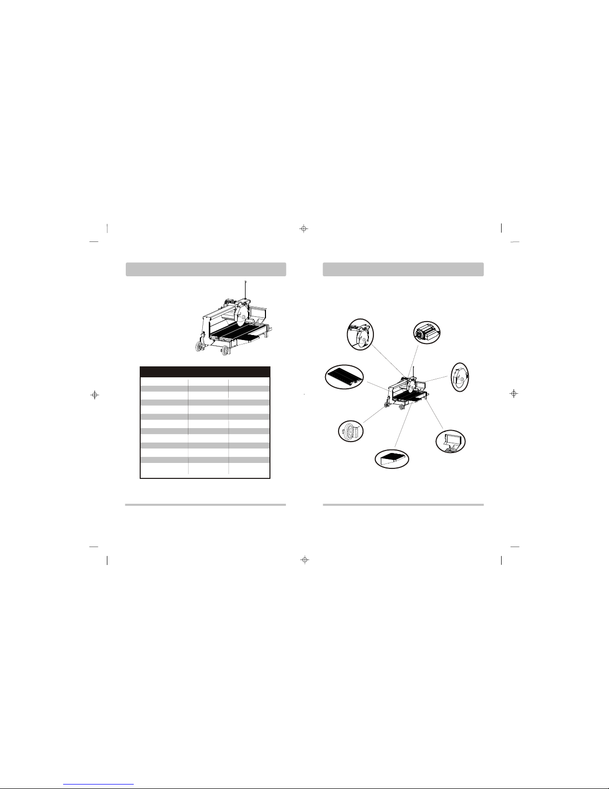
Position Lock
Cutting Head
Removable Extension
Table adds Xtra Workspace
Splash Guard reduces
Water Waste
Rubber Matted
Cutting Table
Blade Capacity of 10”
enhances Cutting Capacity
Powerful 1-1/2HP Induction
Motor cuts larger materials
Sturdy Wheels for
Easy Transport
Induction Motor
3450 rpm
Horse Power
Volts
115 votls
Amps
15 A
Hertz (Cycles)
60 Hz
Motor Type
Stand (Optional)
1010-ST
RPM
Maximum Blade Size
Arbor Size
Maximum Depth of Cut
Straight Cut Length
SPECIFICATIONS 1027 1037
Diagonal Cut Length
Weight
8”-10”
5/8”
2-5/8”
27”
19”
125 lbs.
1-1/2 HP 1-1/2 HP
115 volts
15 A
60 Hz
Induction Motor
3450 rpm
8”-10”
5/8”
2-5/8”
37”
26”
166 lbs.
Slide-In Legs w/Wheels
SPECIFICATIONS
FEATURES
6
5
1. Remove the folding stand
from its box.
2. Swing the working bench
up-right. Open the two legs
and place the work bench on
top of the folding stand.
3. After the saw stand is
completely assembled, place
the saw on top of the saw
stand.
1. Loosen the knurled nuts
securing the blade guard
and remove the guard.
2. Loosen the cutting shaft nut
(left-hand thread); while
loosening the nut, block
the cutting shaft from
turning.
3. Remove the blade
clamping flange. Check
that the contact area
between the blade holder
assembly and the diamond
saw blade is clean.
4. Install the saw blade on the
supporting flange, ensuring
the correct sense of
rotation marked by the
arrow on the blade.
5. Install the blade clamping
flange.
!
Setting the blade too low may damage the
cutting table and if set too high, the blade may
grab the material being cut, causing damage
and possibly injury.
WARNING:
6. Retignten the cutting shaft
nut. Block the cutting shaft
from turning while
tightening the nut.
7. Lightly turn the installed saw
blade by hand and check
the blade for true running.
8. Mount the blade guard.
knurled nuts
Folding Stand (1027 Optional)
1. Make sure the cutting head
is locked.
2. Lifting up one side of the
saw, slide in the legs (with no
wheels) to the front side of
the saw. Lock the wing nut to
tighten the legs in place.
3. Lift up the other side of the
saw and slide in the legs with
the wheels. Lock the wing nut
to fasten the legs in place.
Slide-In Legs (1037)
Easy Transport (1037)
1. Make sure the cutting head is locked.
2. Unlock the wing nut. Lift up the back side of the saw and slide
the legs with wheels,lock the wing nut.
3. Go to the other side of the saw and unlock the wing nut. Lift up
the other side of the saw and insert the legs, lock the wing nut.
Using the legs as handles, tilt the saw diagonally and roll the saw
on the wheels like a dolley.
No. 1010-ST SAW STAND ASSEMBLY
BLADE INSTALLATION
8
7
1. Remove the water pump
from the box and check
that it is not damaged.
2. Place the pump into the
bracket at the right front
corner of the water tray
along its side so that the
water outlet is positioned
horizontally. Connect the
water hose from the blade
guard to the pump and
plug the power cord into
the 3-prong receptacle.
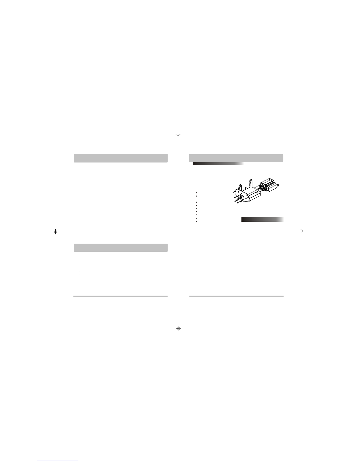
1. Slide the motor into the body of
the cutting head mainframe, holding
the motor front (outer) ring insert into
the mainframe bracket.
2. Holding the cutting head steady,
insert 4 bolts onto the front end of
the motor through the cutting head
mainframe. Lock the bolts tight to
hold the motor in position.
3. Insert the inner flange onto the
blade shaft against the motor’s front
end.
4. Place the blade onto the shaft
making sure the directional arrows
are pointing in the direction of the
shaft rotation. Secure in place with
the outer flange and blade shaft nut.
5. Insert the main long bolt in the
upright of the front plate while
holding the cutting head mainframe,
lock it tight in position. Insert the
second long bolt into the height
adjustment slot and lock it tight in
position. Place the tension spring
into position for height adjustment.
Install the side table and splash
guard as shown in the
illustration to the side. Fasten
the screws respectively to the
saw frame.
CUTTING HEAD INSTALLATION
WATER PUMP INSTALLATION
10
9
SIDE TABLE & SPLASH GUARD
INSTALLATION
WARNING:
!
Disconnect the pump before attempting to handle the pump.
Never operate pump without water in the tray.
3. Fill the water tray so that
the water intake is fully
immersed.
4. Be sure to support the
pump during installation to
prevent pump failure or
damage.
WATER LEVEL TUBE
A tube at the rear end of
the saw filters the debris from the
water produced during the cutting
operation. Debris settles in the water
tray while the water is allowed to
pass through the tube and into the
water bucket, where fresh and filtered
water reside.
Remove the water level tube
from the plastic bag.
Inser t the thin end o f the
tube into the rea r hole
nex t to the wate r pump ,
as shown in the illustration.
1.
2.
3. Fill the water
tray with water.

á The No. 884 Universal Tile
Guide is a two-piece
assembly consisting of a
template base and a
unique detachable ruler
guide. This permits any
cutting angle between 0
and 45 , with 22 and
30 clearly designated.
The ruler guide also
doubles as a measurement
tool to accurately measure
slabs up to a foot in length.
á The Universal Tile Guide
has a locking mechanism
that secures the ruler guide
firmly to the template base.
°
°°
°
°
°°
°
WARNING:
!
Always lock the rip guide prior to transporting the saw.
1. After you have made
yourself familiar with the
components of your saw,
the machine has been
properly set up, the bucket
or water tray is filled with
water, and the electrical
connection is established in
accordance with the
relevant safety regulations,
you may now begin with the
cutting operation.
2. Before you start operation
open the water shut-off
valve.
5. After the cutting operation
is finished, prevent
accidental restarting of the
saw by pushing the
emergency stop from the
switch bracket and
unplugging the power
cable.
3. During the operation, the
user must stand in front side
of the saw, holding the
handle of the swivel-joint
cutting head with his left
hand. The workpiece must
rest on the work table and
should be pressed tightly
against the side and limit
stops with the right hand.
4. Always turn off the saw
before you leave the
machine unattended.
When cutting at constant depth
the cutting head must be pulled
against the workpiece.
1. Before you start cutting, set
the cutting head at the
desired fixed cutting depth.
2. Then use the handle to pull
the cutting head slowly and
uniformly along the guide
rail and across the
workpiece.
3. Push the cutting head fully
back after you finished the
cut.
The handling of larger cutting
depths can be simplified using
the plunge cutting method.
1. In this case, the cutting head
will not be set to a fixed
position while performing
the cut.
2. As you have not fixed the
saw at a defined depth,
Cutting at Constant Depth
Plunge Cuts
The cutting head is freely
movable during seesaw
operations.
3. Hold the handle of the
cutting head with your left
hand and move it to and fro
across the workpiece while
lightly pressing the cutting
head downwards in a
discontinuos movement.
TEMPLATE BASE
DETACHABLE RULER
THE RIP GUIDE (Optional)
OPERATING THE SAW: continued
12
11
OPERATING THE SAW
 Loading...