

Gullberg Janson V80-3P, V130-3P, V250-3P Installation And Maintenance Manual
Installation and Maintenance guide
V80-3P/V130-3P/V250-3P
EN
________________________________________________________________________________________________
Rev. 2015.1
Preface
Congratulations on your purchase of a pool heat pump from Gullberg & Jansson AB. We hope
it meets your expectations and provides you with many years of energy ecient heating.
In this Installation and Maintenance Guide you can read how installation, operation, service
and maintenance are to be performed to ensure correct function. It is therefore important
that you read through the manual carefully before starting or serving the unit. Gullberg
& Jansson can not be held responsible for damage resulting from incorrect installation,
incorrect fault tracing or incorrect maintenance.
Yours sincerely,
Gullberg & Jansson AB
Subject to possible misprints and design alterations. Gullberg & Jansson AB is not responsible for misinterpretations, any obvious
misprints and consequences resulting from these.
FOR YOUR OWN RECORDS
Please complete the details below. Keep these close to hand should anything happen.
Product:
Installed by: Telephone:
Serial number:
Date of installation:
The proof of installation for registration at
Gullberg & Jansson AB is enclosed with the
installation. It is important that this is completed
and posted at the earliest possible date!
!

Table of contents
General information
Product description 4
Functional principle 4
Component part and accessories 5
Important information 5
Transport and storage 5
Installation 5
Use and operation 5
Maintenance procedures 5
Service and support 5
Checklist installation 6
Guarantee conditions 6
Safety Regulations 6
Installation
Outline diagram 7
Positioning the unit 7
Set up 7
Leading o condensation water 8
Pipe connections 8
Bypass coupling 8
Interconnection of multiple units 8
Electrical installation 9
Starting up the unit 9
Use and operation
LCD display 10
Start screen 10
Temperature setting 10
Main menu 11
Temperature values 11
Digital inputs 11
Relay outputs 11
About the software 11
Setting time and date 12
Error messages 12
Maintenance, service and
fault tracing
Winter drainage 13
Maintenance 13
Fault tracing 13
Error code table 13
Fault charting table 14
Technical specication
Connection key PC4001 15
V80-3P/V130-3P 16
Wiring diagram 16
Technical data 17
Dimensions and connections 17
V250-3P 18
Wiring diagram 18
Technical data 19
Dimensions and connections 19
General information
Product description
The models V80-3P/V130-3P/V250-3P are a range of
specically developed air/water heat pumps designed for
energy ecient heating of swimming pools or spa facilities.
The models have been developed and designed for the
Nordic climate. The pool heat pumps are designed to
work with good eciency and a low noise level.
All models feature:
• Titanium heat exchangers resistant to chlorine and salt
water
• Environmentally friendly and eective refrigerant (R410a)
• Digital LED control
• Dynamic defrost function
• Built-in ow switch
• Union or anged connections depending on model
Functional principle
The pool heat pumps are V80-3P/V130-3P/V250-3P primarily
used for heating, but can also be used for cooling. The
models are controlled via a ow
switch and in order to work the pool’s circulation pump must
be running.
The pool heat pump works with the greatest energy
eciency when there are small dierences in temperature
between the inlet and outlet. The recommendation is 1-2
degrees dierence between the inlet and outlet. The water
ow is regulated via a bypass coupling. Read more about the
bypass coupling in section 2 – Installation.
All models are developed to guarantee good eciency in
the Nordic climate. However, it is important to be aware that
the degree of eciency is dependent on the surrounding
outdoor temperature and the temperature of the pool
water. The heat pump can be seen to perform with dierent
eciency during dierent parts of the year depending on
the outdoor conditions. At the start of the season, when
the water in the pool is cold, the heat pump needs to
work continuously for a long period to produce the right
temperature in the pool. When the pool water has reached
the required temperature, the heat pump automatically stops
and starts as required. It is always cost-eective to cover the
pool when not in use, especially at night. Approximately 60
– 70 % of the heat disappears from the water surface of the
pool. Covering also reduces the heat pump’s running time.
The heat pump must always be installed outside as it draws
its energy from the surrounding air. It must be well ventilated
and must not be enclosed or in any other way shielded so the
air circulation is impaired. The circulation of the air between
the intake and exhaust impairs eciency
Frost or ice can form on the heat pump’s evaporator. This is
completely normal. An automatic defrosting cycle will start to
melt the ice. After the defrosting cycle the heat pump starts
its standard program and continues to heat the pool.
The swimming pool heat pump normal working
condition is between 5 and 40 °C ambient temperature and
between 15 and 40 °C inlet water temperature.
This chapter provides background information about the pool heat pumps covered in this Installation and Maintenance Guide.
Important information, guarantee conditions and safety instructions are also presented here. This chapter is intended for both users
and installation engineers.
1
4
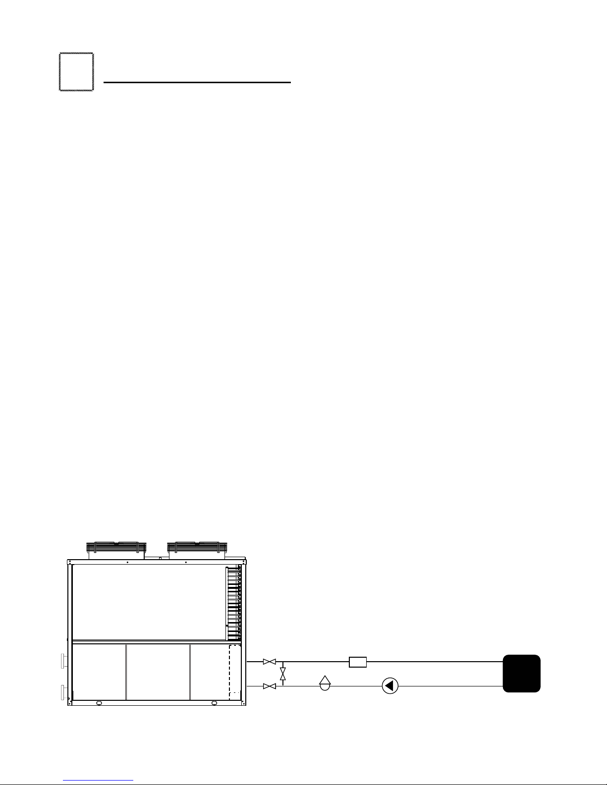
POOL
Refer to the labels on the unit before connecting the inlet and outlet.
Chlorinator
Sand lter
Circulation pump

General information
5
Component part and accessories
1. Main unit – V80-3P/V130-3P/V250-3P
2. Installation accessories
• Installation instructions
• LCD display with 20 metres of cabling
• Union couplings (V80-3P/V130-3P only)
• Damping rubber blocks (V80-3P/V130-3P only)
Important information
You can read about some especially important points
concerning transport and storage, installation, usage,
maintenance and fault tracing below.
Transport and storage
Models designed to be transported vertically must be
transported in this way. This is because the suspension inside
the compressor can be damaged if the unit is laid down. If
the heat pump is tilted during installation or draining this
should be done with care and for the shortest time possible.
The original packaging is intended to be used to reduce the
risk of transport damage.
Installation
The pool heat pump must be installed by a qualied
installation engineer and placed outdoors. The unit must
stand rmly, straight and raised from ground level. Provide a
rm and at surface.
Noise propagation must be taken into consideration when
positioning during installation. Positioning of the unit must
be done so that noise from the compressor and fan disturb
the environment as little as possible.
Large amounts of melt and condensation water can be
discharged during defrosting and operation. Consequently, it
is important to provide good drainage and run-o. The
units must stand freely so that air is not prevented to pass
the evaporator. Avoid a placement that produces cold air
circulation as this reduces the output of the heat pump.
In a combination involving solar collectors, you should
ensure that hot solar collector water does not ow directly to
the pool heat pump. If the solar collector water becomes too
hot you risk damaging the heat pump beyond repair.
Use and operation
The parameters on the display are set at the factory and do
normally not need to be adjusted. The temperature is set
to 27 °C. If you wish to increase the temperature, check rst
to ensure that your wishes of a high temperature do not
contravene any guarantees concerning the general pool
construction.
Maintenance procedures
Perform regular checks to ensure that the inlet grille is not
blocked by leaves, snow, etc. In addition, make sure that
excessive frost or ice does not build up below the unit during
cold weather conditions.
The outer case can be cleaned using a damp cloth if
necessary. Take care not to scratch the unit.
If the pool heat pump should be out of service over the
winter, it is important to drain the unit of water. The
guarantee does not cover damage due to freezing on
account of insucient maintenance. The heat exchanger can
also be ushed out to remove any remaining deposits ahead
of winter drainage. Read more about drainage in section 4 Maintenance, service and fault tracing.
Service and support
The pool heat pumps are designed for reliable operation and
a long life. If a fault should occur you are advised to contact
the installation engineer who carried out the installation.
Always specify the product serial number, which you will nd
under the rating plate on the long side of the heat pump.
A basic guide to fault tracing is presented in section 4 Maintenance, service and fault tracing.
The unit may only be repaired by a qualied installation
engineer or an accredited workshop. Original spare parts
must be used for repairs.
Installation material is enclosed inside the
machine. Open the cover and remove the
material before installation. Note that the
installation engineer provides pipes and
the bypass coupling for the installation.
!

General information
6
Checklist installation
The following checklist provides a general description of how
the installation is carried out.
; Place the heat pump on a rm and horizontal surface.
; Open the service hatch and remove the enclosed
installation kit. Ensure that all component parts have
been delivered.
; Route the pipes for incoming and outgoing water.
Exercise care to ensure the inlet and outlet are installed
correctly. Mount the heat pump after the sand lter.
; Install a bypass for regulating the right partial ow for
the pool heat pump.
; Connect the electricity.
; Energise and check the settings.
; Put in operation and adjust the ow to the pool heat
pump to the right level.
Read more about start up in section 2 under the heading –
Starting up the unit.
Guarantee conditions
The component parts of the system must be transported,
stored and installed in accordance with the provisions
set out in the manual.
Repairs must be carried out by a qualied engineer. Original
parts must be used for repairs.
The guarantee becomes void if the conditions above are
violated.
Safety Regulations
It is especially important to take into account the following
safety instructions when handling, installing and using the
heat pump:
• Only qualied persons may work on the product’s
cooling system.
• Always disconnect the power supply before working on
the system.
 Loading...