

Gulf+Western ACWC-SC Service Manual

MODEL
Screw Type
ACWC-SC
SERVICE
I & 0 6500A
MANUAL
PACKAGED
INSTALLATION,
MAINTENANCE
DESCRIPTION
Inspection & Handling
Location & Mounting ........
Wiring
Chiller
Start-Up
Maintenance
Slide Valve
Low
Control
Unit
Sequence
Sequence
Control
Control
Power Wiring Diagram
Power
Electrical Data
Cooler
Unit
Troubleshooting
Causes & Prevention
Start-Up
Operating
..............................................................................................................
Piping
Ambient
Settings
Operating
Models ACWC-160SC
Model
Wiring
Models ACWC-160SC
Wiring
Model ACWC-215SC
Across-The-Line
Wiring
Star-Delta
Pressure
Loading/Suspension
.....................................................................................................
........................................................................................................
.................
Unloading
Operation
Limitations
of
Operation
of
Operation
ACWC-215SC
Diagram
Diagram
Diagram
...................................................................................................
Check
Data
List
...
...........................................................................................
System
.........................................................................................
..................................................................................................
......................................................................................
......................................................................................
..................................................................................
....................................................................................
.............
Start
..........................................................................................
Drops
..........................................................................................
Guide
.................
of
Freeze-Up
.....................................
.....
...........
AIR
COOLED
CHILLERS
OPERATION
&
INSTRUCTIONS
TABLE OF
...
......
...............................................
.....
..................................
..................................................................................
......................................................................................
Thru
200SC
Thru
200SC
....
....
........
Points
..............................................................................
....
...........
............................................................................
........
....
..............................
CONTENTS
...
....
....
..............................
...
......................
.
.....
.. ..
..............................................
...........................
.........................
...................................
......................
.....
...........
...
............
PAGE NO.
....
2 & 3
6 & 7
8 & 9
10 &
12-15
.
........
...
......
.. 20
2
2
2
2
3
4
5
5
5
11
16
17
18
18
18
. 19
19
20
BOHN
A Gulf+Western
Danville,
..
!
HEAT TRANSFER
Company
Illinois
61832•{217)446-371 0
I
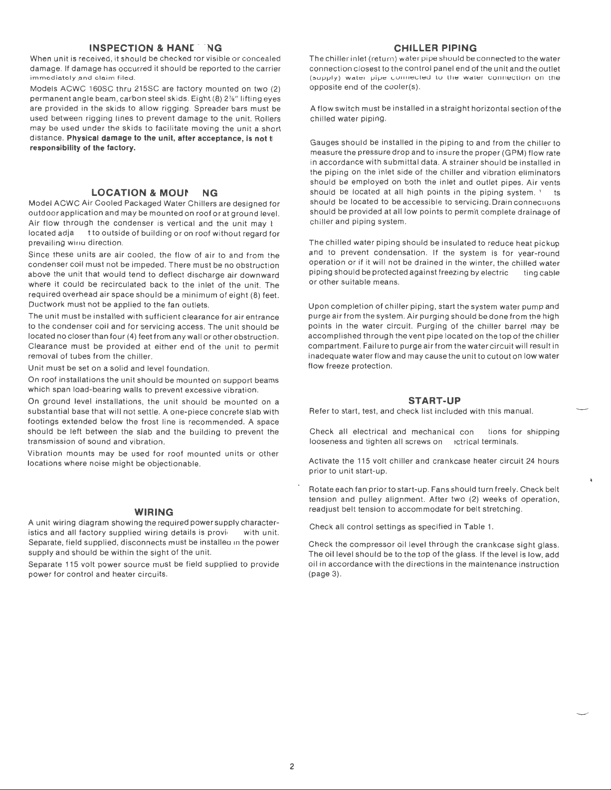
When
unit
is received,
damage
immediately .o.nd
Models
permanent
are
used between
may be used
distance
responsibility of the factory.
. If
damage
ACWC
angle beam,
provided
in the
under
. Physical damage to the unit, after acceptance,
has
clo.im
160SC
skids
rigging
it
should
occurred
filed
thru
carbon
lines
the
skids
LOCATION & MOUNTING
Model
ACWC
Air
Cooled
INSPECTION & HANDLING
outdoor
Air
located
prevailing
Since
condenser
above the
where
required
Ductwork
The
to
located
Clearance
removal
Unit
On
which
On
substantial
footings
should
transmission
Vibration
locations
application
flow
through
adjacent
wind
these
coil
unit
it
could
overhead
must
unit
must
the
condenser
no
closer than
of
tubes
must be set on a
roof
installations
span
ground
extended
be left between the
mounts
where noise
to
direction.
units
must
that
be
not
be
installed
must
be
from
load-bearing
level
base
that
of
sound
Packaged Water
and
may
the
condenser
outside
are
air
not
be impeded.
would
recirculated
air
space
be applied
coil
and
four
provided
the
solid
the
unit
walls
installations,
will
not
below
and
may
be used
might
be
it
.
215SC are
steel skids. Ei
to
allow
to
prevent
to
facilitate
be
mounted
is vertical and the
of
building
cooled,
tend
to
back
should
to
the fan
with
sufficient
for
servicing
(4) feet
from
at
either
chiller
.
and level
should
to
prevent excessive
the
settle. A
the
frost
slab
and
vibration
for
be
objectionable.
checked
should
rigging.
the
deflect
unit
line is recommended. A space
.
for
be reported
factory
Spreader bars
damage
moving
Chillers
on
or
on
flow
of
There
must
discharge
to the
be a
minimum
outlets
clearance
access. The
any wall
end
foundation
be
mounted
should
one-piece
the
building
roof
mounted
visible
mounted
ght
(8) 2W'
to
roof
or
roof
without
air
inlet
.
or
other
of
the
.
on
be
concrete
or
concealed
to
the carrier
on
lifting
the
unit. Rollers
the
unit a short
are
designed
at
ground
unit
regard
to
and
be
no
obstruction
air
downward
of
the unit. The
of
eight
for
air
unit
should
obstruction
unit
support
vibration
mounted
to
prevent
units
two
eyes
must
Is
not the
level.
may be
from
the
(8) feet.
entrance
to
permit
beams
.
on a
slab
with
the
or
other
(2)
be
for
for
be
The
CHILLER
chiller
inlet
(return)
connection
(:.upply)
opposite
A
flow
chilled
Gauges
measure
accordance
in
the
should
should
should
should
chiller
The
and
operation
piping
or
other
Upon
purge
points
.
accomplished
compartment.
inadequate
flow
closest
vvdte• 1-'ifJt::
end
of
switch
must
water
piping
should
the
pressure
with
piping
on the
be
employed
be located at all high
be located
be
provided
and
piping
chilled
water
to
prevent
or
if
should
completion
air
in
freeze
it
be protected against freezing by
suitable means.
from
the
the
water
through
Failure
waterflow
protection.
water
to
the
control
<..v""""'t"'u
the cooler(s).
be installed in a
.
be installed in
drop
submittal
inlet
side
on both the inlet and
to
be accessible
at all
low
system.
piping
should
condensation. If
will
not
be
of
chiller
system .
piping,
Air
circuit.
the
vent
to
purge
and may cause the
pipe
the
and to
data. A
of
the
points
points
be
drained
purging
Purging
pipe
air
PIPING
should
be
panel end
tv
straight
piping
insure
chiller
insulated
start
from
of
u,.,
wat.,r
horizontal
to
the
strainer
and
in the
to
servicing
to
permit
the system is
in the winter,
the
system water
should
of
the
located
the
water
unit
connected
the
unit
<,;urrrr.,<,;llun
and
from
proper
(GPM)
should
vibration
outlet
pipes.
piping
system . Vents
. Drain
complete
to
reduce heat
for
the
electric
be
done
chiller
barrel may be
on
the
top
circuit
to
cutout
to the water
and the
outlet
on
the
section
of
the
the
chiller
flow
be
connections
chilled
heating cable
from
of
will
on
rate
installed
eliminators
Air
vents
drainage
pickup
year-round
water
pump
and
the
high
the
chiller
result in
low
water
to
in
of
..
Refer
to
start, test, and
Check
all
to
electrical
unit
start-up
looseness and
Activate the 115
prior
START-UP
check
and
tighten
volt
mechanical
all screws on electrical
chiller
and crankcase heater
.
list
included
connections
with
terminals
this
manual.
for
.
circuit
shipping
24
hours
~·
A
unit
wiring
istics
and all
Separate, field
supply
and
should
Separate 115
power
for
control
diagram
factory
supplied,
be
volt
power
and heater
WIRING
showing
supplied
disconnects
within
the
source
circuits
the required
wiring
sight
must be field
power
details is
must be installed in the
of
the unit.
.
supply
provided
supplied
character-
with
unit.
power
to
provide
Rotate each fan
tension
readjust
Check
Check
The
oil in
(page 3).
2
and
pulley
belt
tension
all
control
the
compressor
oil
level
should
accordance
prior
alignment.
settings
be
with
to
start-up
to
accommodate
as
specified in Table
oil level
to
the
top
the
directions
. Fans
should
After
two
through
of
the glass. If
in the
turn
(2) weeks
for
belt stretching.
1.
the
crankcase
the
maintenance
freely.
Check
of
operation,
sight
level is low, add
glass.
instruction
belt
.
--..,_

. CAUTION:
The
discharge
sor. Liquid
All compressors are soli a mountea on 1sopads, therefore,
hold-down
cause excessive
refrigerant
hold-down
line valve
line valves
bolts
line breakage.
bolts
must
must
not
vibration
for
tightness .
must
be open
also be open
be loosened.
of
the
Prior
to
before
for
sustained
Loosening
compressor
start-up
check
starting
and may result in
MAINTENANCE
CONDENSER
Units
equipped
motors
. Fan belts, fan
maintenance
1. Fan Belts
nearly
should
maintain
checked at three (3)
2.
Fan
Bearings-
the
relubricatable
fittings,
recommended
is
with
a hand
sticker
3.
Motor
Bearings-
bearings
must
be
time
a bearing can run
will
depend
operating
hour
2000
clean closed
grease-free
Lubricant
The
air
regular
with belt drive fans have
as
-After
reached
be
good
accessible
attached to the unit.
consume
present
conditions
operating
should
inlet
preventative
bearings
follows:
two
(2) weeks
their
checked
fan and
gun
upon
container
from
of
permanent
again and
motor
month
Each fan shaft is
type
. Each bearing is provided
through
the bearings be greased
. The suggested greasing interval is
Each
motor
a very small
at all
time
without
the
operating
, the
motor
intervals. The
and
solid
fillers
have a safe
the
condenser
maintenance
and
motor
bearings
operation, the
stretch,
proper
operation
intervals.
the
individual
is
equipped
amount
to prevent
having grease added
bearings
should
or
operating
coil
adjustments
, the belt tension
provided
of
motor
conditions. Under
lubricant
be an
anti-friction
other
temperature
should
be
program
inherently
therefore
with
motor
by
adding 4 to
with
ball bearings. Ball
lubricant, but
injury.
should
should
harmful
kept
.
the
compres-
operation
compressor
these
all
compressor
require
belts will have
, each belt
ball
bearings
with
access panels. It
indicated
The
or
be
lubricated
type
ingredients
of
clean
bolts
will
protected
periodic
made.
To
should
grease
5 shots
on a
enough
length
replaced
normal
be
from
bearing
2000° F.
through
.
be
of
of
at
Locate
the
UL-3
residual pressure
Pump
glass.
Replace the
Do not
Place
jumper
#4
on
valve
on TER4 to energize
the
normal
2.
RECOMMENDED
SR-30
discharge
(see
drawing
oil
into
this
discharge
allow compressor to run with discharge valve closed.
the
system
wire, make a
terminal
feeding
operat
the
ional
operation
refrigeration
Do not add any other type of oil
Do not operate compressor
pressure
below)
by
pushing
flU'
t
u11til
port
"ON-OFF"
"short" for
block
TER5 and the
circuit
SOL
temperature
.
OIL-
oil.
port
; remove
u,.,
cap
switch
you
have
1 ). Reset return
The
If
adjacent
in on the pressure
setting and
unit
oil level
the
uil
level
. Re-open the discharge line valve.
in
the "ON" position. Using
five (5)
seconds
switched
just
"blown
is
factory-charged
to
this factory charge.
is
to
cap and release the
port
Is
to the
tOP
between
terminal
" (e.g.
water
thermostat
allow
unit
below one-half
solenoid
fitting
Of
the
terminal
of a solenoid
terminal
(~1)
to
return
with
BOHN
('h)
valve
itself.
sight
a
#121
to
to
sight
glass.
If
the
oil
level is
below
the
type
the
hand
outlined
no
reduction
minimum
refrigeration
and will not mix
screw
Agency
SR-30 is
then refill
oil is
not
than these
It
obtained
SUNISO
capacity
3.
COMPRESSOR REPAIRS (Internal) -
authorized
suspected .
of
the
attempt
is
suggested
not
on hand , you may drain the entire factory oil charge,
with
SUN ISO 4GS
synthetic
to
operate
two
specified above.
that a gallon
and kept on
4GS oil, as
loss, and
BOHN
Service
4. COMPRESSOR REPAIRS (External) -
a
.
a
unloaded
valves UL-1 ,
may be repaired
start,
UL-2
loading
, and
and UL-3.
or
replaced in the field ,
Any
specified
compressor
or
more
at the
job
above,
in
input
if a
compressor
unloading
of
these three (3) solenoid valves
oil. The
with
of
BOHN
site. The
will
result
K.W.
Contact
Proper
is
controlled
as
required .
above, and
factory
SUN
with
substitution
in a
factory
malfunction
HIGH
BOHN
(BOHN)
ISO 4GS. Do
any
oil
other
SR-30
oil
be
2%
to
4%
or
an
operation
by solenoid
PRESSURE
PORT
of
is
of
1.
OIL LEVEL -
checked
stopped
must be added .
Oil
should
turn
the
setting
, and
system "
valve in the
Refrigerant
approximately
35 PSIG,
discharge
after
the
COMPRESSOR
The
oil
periodically,
. If
the
be added
return
wait
ON-OFF" switch
discharge
pressure
80 to 90 PSI G.
but
the residual
check
compressor
oil
water
for
valve)
level is
with
only
thermostat
the
line between
inside
stops.
level in the
the
compressor
below
one-half
with
the
unit
to
pumpdown
in the "OFF"
of
the
The
discharge
will
equalize
compressor(s)
either
(
'12
) the
compressor
(T1) to a
compressor
compressor
low
pressure
pressure (upstream
back
higher
and
position
into
shut
shutoff.
cut-out
the
should
running
sight
glass, oil
off. To
temperature
Place the
. Close
and
condenser
will
setting is
suction
do
the
now
of
be
or
so,
line
.
be
the
side
3

SLIDE
VALVE
UNLOADING
SYSTEM
1 ne
tlonn
screw
modulation
operator
valves (UL-1,
The
rotors
the
capacity
Upon
to
position. After
established
temperature
response
The
pressure, whenever
internal
slide
turn;
effective
.
compressor
act
upon
slide
to
valve
compressor
consists
to
UL-2 & UL-3)
valve
forms a portion
thus,
its
rotor
the
hydraulic
30 seconds,
to
all
bearings
controller
the
supply
will
of a slide
the
position
length
start-up, UL-3
move
UL-1
capacity
compressor;
piped
with
and
piston,
during
surfaces,
is free
water
temperature
to
the
opens
Load
¢::J
valve and
plus
externally.
of
the
respect
thereby
is opened.
holding
which
UL-3
to
open
left
(loading)
to
permit
Slide Valve
control
system
hydraulic
three
chamber
to
the
This
it in
is
closed. At
and close UL-1
.
flow
piston/cylinder
hydraulic
wall in
the
rotors
percent
allows
the
time
full
by
force
to
the
fully
this
oil
Unload
c::>
for
infinite
solenoid
which
determines
of
full load
oil pressure
unloaded
oil
flow
point,
or
UL-2
of
discharge
return
(low
Oil Pressure
the
is
the
in
pressure) line.
whenever
force
The
"
pulses" to
The
point,
will
approaches
overshooting
This
water
resulting
water
UL-2
of
the
oil
temperature
the
further
the
the
longer
continue
until
the
method
sensing
in an
temperature
The
slide
opens
the
exceeds
controller
appropriate
supply
water
is
the
the
controller
set
point, the
the
set
point.
of
compressor
minimizes
exceptionally
.
Hydraulic
valve
will
oil
supply
that
of
the
sends a series
solenoid
temperature
duration
Piston
of
is satisfied. As
pulses
unloading
action/reaction
precise
move
to
(high
pressure) line,
discharge
to
adjust
is
the
pulses.
become
in
conjunction
lag
and
stable
the
gas.
of
power
from
The
the
quite
time
Vent
Suction
right
to
load
the
water
control
(unloading)
since
(energizing)
conditions
controller
series
of
temperature
brief
to
with
and
overshoot
of
to
the
set
pulses
prevent
supply
supply
.
r
Screw
Rotor
The
following
operating
modes.
Starting
Loading
Unloading
table
Oil
Pressure Lines
lists
solenoid
UL-1
Close
Open
Close
UL-1
Oil
Return
valve
position
UL-2 UL-3
Close
Close
Open
Open
Close
Close
for
all
three
Oil
Supply
~
'-...../'
4

Due
to
the
wide
operate
summer
below
the
valve
control
system
ambients
the
conditions.
60°
F.
evaporator
operation
with
control
indicated:
MEDIUM
(STANDARD
A
fan
cycling
Chillers
conditions
This
cycled
two
five-fan
units.
sequence, in
to prov1de
is an
on
and
compressors
units;
With
one
High
(Manual
Pumpdown
(Auto
Fan
(Adjustable)
Low
(Manual
LOW
range
Air
Cooled
the
pressure
is
below
. As a
the
possibility
are
control
to 30° F.
automatic
off
, as
running, three
four
compressor
response
of
applications,
Packaged
Without
available
differential
the
level
result,
FAN
proper
the
of
allowing
CYCLING
AMBIENT
EQUIPMENT
is
standard
prop
er
operating
operation
required,
fans
on
six-fan
running,
to head pressure.
it
is
Water
Chillers
control,
between
to
insure
unit
may
evaporator
the
CONTROL
-FACTORY
on
all
Air
head pressures, in
in
which
in
response
fans
are
units
; and five
all
but
sometimes
at
ambients
when
ambients
the
proper
freezing.
units
Cooled
the
cycled
the lead fan are
condenser
thermal
cycle
on
to
TO
INSTALLED)
Packaged
condenser
to
head
(in
fans
Three
operate
30°
pressure.
AMBIENT
necessary
below
expansion
low
pressure
types
at
F.
Water
ambient
fans
sequence)
on
seven-fan
cycled
drop
and
the
are
With
on
to
of
in
OPERATION
This
by
pressure
All
the
prevent
All
auxiliary
heater; the
thermostatically
The
junction
pressure
provides
prevent
ACWC-SC
CONTROL
PRESSURE
Pressure
Reset)
Cycling
Pressure Freeze
Control
Reset) HP2 & HP3
Control
Pressure
Reset)
--
ACTUATED
Control
Control
SETTINGS
LPF 2 & LPF-3
arrangement
delaying
is
provides
the
condenser
obtained.
GRAVITY
AMBIENT
LOW
(OPTIONAL
condenser
fan
discharge
convection
compressors
heater
standard
with
down
an
nuisance
LEGEND
HP-1
PD1
PD2 & PD3
2 Fan
Cell
FCP 1
FCP 2 295
Cell
3 Fan
FCP 1 260
FCP 2 275
FCP 3
4 Fan
Cell
FCP 1
FCP 2 275
FCP3
FCP4
LPF 1
EQUIPMENT-
fans
are
to
minimize
drafts
are
enclosed
is
included
temperature
controlled
condenser
the
discharge
to
oo F.
electrical
tnp-out
equipped
bypass
Cut-In
positive
fan
start-up
operation
control
until a predetermined
down
(Discharge) DAMPERS
CONTROL
FACTORY
with
the
effect
up
through
in
individual
to
supplement
within
the
compressor
.
fan
cycling
dampers, will
ambient. A 90-second
around
during
Cut-In
Cut-Out
Cut-In
Cut-Out
280
290 215
260
285
295
Cut-Out
the
cold
FACTORY
(PSIG)
gravity
of
prevailing
the
condenser
insulated
the
package,
maintain
low
start-up.
SETTING
TO
oo
INSTALLED)
dampers
coil
standard
compartment
operating
time
pressure
300 PISG
365 PSIG
55 PSIG
35 PSIG
Cut-Out
170
180
160
175
160
175
210
235
54 PSIG
to
+30°
F.
mounted
winds;
and
in
still
housings.
crankcase
in
suitable
delay
freezestat
F.
head
on
to
air.
An
is
conhead
relay
to
(.
"'-._./
-
Chiller
Low
Chiller
Water
Chiller
Heater
(Non-Adjustable
Oil
Temperature
(Adjustable)
Manual
Capacity
1.
Maximum
2.
Maximum
3.
Maximum
4.
Units
Unit
must
must
5.
TEMPERATURE
Water
Cycling
Thermostat
Reset
Control
ambient
allowable
allowable
not
have leaving
be
allowed
Temperature
Thermostat
Safety
Control
Thermostat
air
to
condenser
cooler
water
temperature
to
pumpdown
ACTUATED
Thermostat
(Adj.)
water
water
(Adjustable)
Mode
Control
is 115° F. (60
pressure
temperatures
to
at the
is 150 PSI G.
cooler
end
UNIT
is 75°
of
of
each
Hertz
42°
Position
OPERATING
operation).
F.
F.
or
lower
operating
5
LEGEND
T2
T1
Included
CBH1
LIMITATIONS
unless
cycle
With
Heater
OTS
1
OTS
2
OTS3
T3
used
(except
with a glycol
on
safety
control
FACTORY
Cut-Out
Dial Set
Dial Set
solution.
At
Cut
-In 40°
Cut-Out
Cut-Out
At
shutdown).
SETTING
37°
55°
45°
240°
44°
F.
F.
F.
F.
F.
F.

The
theory.
12
[12]
(RS)
~
~
@
&
wiring
diagrams
The
following
Line
number
Line
number
Component
Normally
Normally
Holding
Note
number
and
key
on
wiring
in
text
identification
open
contact-
closed
contact-
coil -line
sequence
shows
how
diagram
symbol
line
number
KEY
instructions
the
in
number
line
number
location
TO
on
indexing
text
(Relay #5)
location
location
30
WIRING
the
system can be used.
~
DIAGRAM
following
EXAMPLE
§]
pages have been devised
§]
INDEXING
SYSTEM
to
@@&
for
The
line
#44;
the
which
~
The
contacts
lines 66, 23, and 54.
This
is
the
number
simplify
holding
(reading
the
holding
holding
The
identifies
the
understanding
coil
for
the
from
left
coil
for
coil
shown
contact
the
line
to
on
first
right)
the
on
line
of
and
See
contact
can
second
this
line
23 is
wiring
tracing
Note
shown
be
found
contact
found
can
normally
shown
of
Number
on
line #74.
be
found
at
the
circuit
on
this
on
line
can be
closed
left.
3
on
.
SEQUENCE
MODELS
The
following
200
SC
wiring
Important Notel
The
compressor
active
PRELIMINARY
Place
"OFF"
temperature.
Activate
3] on
terminal
up
to
the
(R19) (3]. (R20)
power
to
the
chiller
3) (8,
(SCH1,
Close
the
indicating
will be two phase loss monitors, (PLM1) and (PLM2),
models).
the
compressor(s)
the
compressors
at
the
leads on
run
backwards,
COMPRESSOR WARRANTEE!
Start-up
the
water
#12 (58] and #13 [60]
sequence
(see Pages 10
diagram
Control
Circuit
for a minimum
control
position,
the
115
control
to
the
compressor
barrel
9,
1 0]
2,
3)
[3,
main
light
This
Main Incoming Power Terminal Block.
the
phase loss
the
chilled
flow
and
furnished
Identification
Line
crankcase
fa
SEQUENCE
circuit
"ON-OFF"
and set
volt
electrical
board
(TEAS)
circuit
[5].
and
heater
(optional),
5,
7]
(optional).
power
disconnect
on
the
phase loss
light
must
. If
the
will
not
causing
water
switch
completes
of
monitor,
OF
OPERATION
ACWC
of
operation
11
with
Number
24
hours
the
switches.
(R21) [7] are
crankcase
(CBH1)
and
be on
light
be
severe damage, and WILL VOID
pump.
terminal
160
for
typical
unit
for
Symbol
heater
must
prior
switches
staging
service
to
distribute
Crankcase
heaters.
(11].
the
low
switch.
monitor
to
indicate
is
not
on,
energized.
for
this
The
an
electrical
board (TEAS).
To
200
SC
is
typical
for
the
wiring
diagram).
specific
to
thermostat
to
the
ambient
Reverse
water
information.
be
energized
unit
start-up.
(SW1
thru
(T1)
terminals
power
to
the
heater relay
closed
and are
Power
receiver heaters (RH1,
crankcase
Check
to
(PLM1) is
proper
main
DO
allow
flow
circuit
phase
control
any
NOT
the
is
Terminals
the
will
ACWC
Refer
and remain
SW4) in
to
its
highest
#2 and #4
control
contacts
supplying
is also
supplied
heaters
see
that
lit
confirmed
across
the
(NOTE: There
on
208-230 volt
rotation
circuit
two
phase legs
reverse
compressor
terminals
#14 [61]
160
to
the
the
[1
and
circuit
red
for
the
THE
when
to
Upon
(T1)
[62].
safety
compressor
allowing
close,
controls
and 17). Fan
2,
the
NOTE: ALL FAN
Relay (R19) [20]
crankcase
energizing
to
minutes.
TIMES
to
Time
in an
out,
[74].
solenoid
solenoid
and #15 [63]
either
compressor
Set
the
54°
F.
return
design
the
Place
position, thus
system will
compressor will start.
demand
will
closing
controls
bringing
"cut-in"
delay relay (TD1 0) [63]
unloaded
it
will
This
provide
contact
is
running.
staging
water). Set
range
of
four
be
for
close, energizing
(R1)
No.1
the
compressor
(FCP1) and (FCP2) (see
motor
setting
FAN
CYCLING
DIFFERENT HEAD PRESSURES.
heater(s). Relay (R14) (19]
(TD7) [23].
COMPRESSOR
OUT.
energize
allows
valve
(UL
valve (UL2-1) [74].
an
(R14). (R16),
thermostat
operation
(4)
energizing
In
and
power
contact
condition
the
control
the "Time-In" mode for five minutes before any
STAGE 1
cooling,
contacts
switches
and
liquid
to
#1
will
of
(FCP1
MOTORS
7-1
This
relay (R4) [27].
the
capacity
1-1) [71].
interlock
(T1)
(e.g. 44°
circuit
the
the
relay (TD10) (63] and
7-4 [22]. 8-5 [25].
line
to
start. Fan
the
start
CONTROL
[3] opens,
will
#2
contact
for
loading
unloading
for
the
water
or
(R18) [62]
to
the
design range
capacity
are closed,
).
ARE
CANNOT
30 seconds. When relay (TD10)
control
F.
supply
switches
balance
first
line
as
force
control
of
LOADING
step
solenoid
contactor
side
Power
Wiring
soon
as
CONTROLELD
AND
de-energizing
compressor
BE
C-NC
closing
thermostat
the
compressor;
the
the
of
the
(SOL
of
the
contact
STARTED
(26]
contacts
compressor.
pump
will
close
of
thermostat
water) .
(SW1-SW4) in
control
the
staging
staging
and
control
1) (25]
(C13) (21]
fan
cycling
Diagram-
head
pressure
BY
WILL
8-5 (24] closes ,
#1
holds
the
9-6 [71] and 7-4
(T3)
starter(s);
any
time
operation
9-6 (16]. If
circuit
will
THEIR OWN
CUT
compressor#1
to
UNTIL
compressor
or
(e.g.
(T3)
to
the
the
"ON"
circuit.
The
thermostat
relay (R1)
the
[16]
for
energize,
will
also
pressure
Pages 16
reaches
IN
AT
run
for
five
(TD7)
times
to
energize
to
energize
a
,
-~
\....__./
6
 Loading...