

Gulfstream Aerospace G550 Operating Manual

OPERATING MANUAL
Title Page
Prev Page
Next Page
TOC
INDICATING / RECORDING
2A-31-10: General
1. Honeywell PlaneView System Indicating and Recording Architecture:
The indicating and recording systems of the Gulfstream G550 reside within a
highly integrated hardware and software architecture provided by the Honeywell
PlaneView system. PlaneView incorporates software avionics functions hosted on
processor cards and modules installed in three (3) Modular Avionics Units (MAUs)
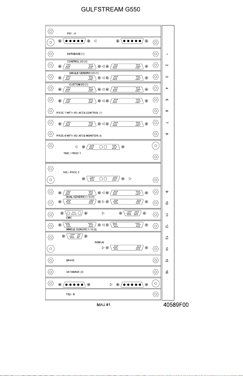
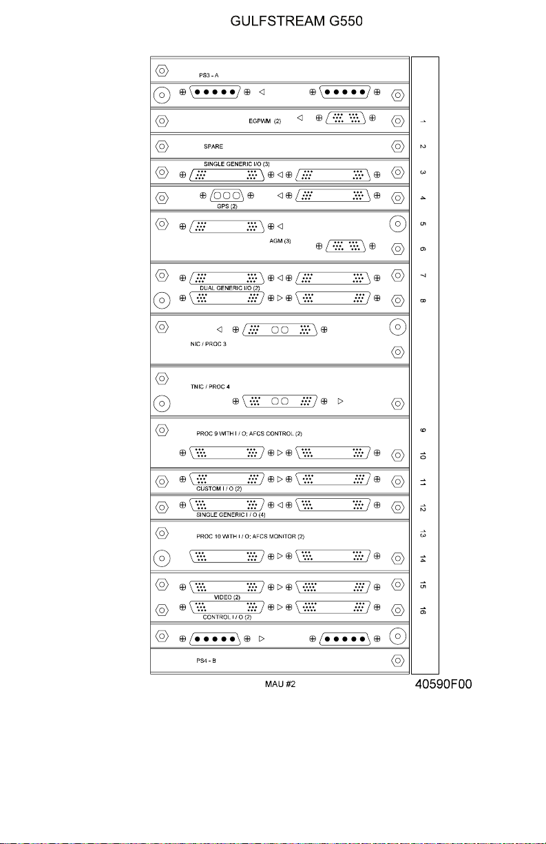
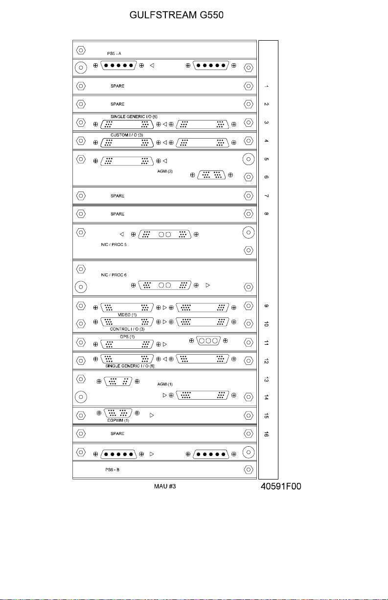
and two (2) Modular Radio Cabinets (MRCs). (The MAUs are depicted in Figure
1, Figure 2 and Figure 3.) The avionics functions communicate within the MAUs
over a digital bus called the Virtual Backplane Peripheral Component Interconnect
(VbPCI) using a Periodic Device Driver (PDD) and a Backplane Interface
Controller (BIC). Each MAU has two (2) channels, A and B with each channel
powered redundantly powered by a primary and secondary DC power source. The
dual channel, dual power source configuration provides both redundancy and
flexibility for module installation, since some modules require connection to only a
single channel while other modules must have dual channel connections. Each
MAU is also equipped with an internal fan to provide module cooling.
The processor cards and modules within the MAUs and the communication
modules residing in the MRCs exchange data over four (4) redundant version D
Avionics Standard Communication Buses (ASCB-Ds) through Network Interface
Controllers (NICs). The ASCBs and NICs provide bidirectional software
communications at 20 Mb/sec with a frame rate of 80 Hz. The ASCBs are
supplemented with a Local Area Network (LAN) that provides both a Data
Management Unit (DMU) and Personal Computer (PC) interface for loading
software data and performing maintenance analysis and testing. All data flow
within the PlaneView system is governed by a Digital Engine Operating System
(DEOS) that provides space partitioning to ensure the memory integrity within all
avionics functions and additionally provides the timing separation that allows
multiple software functions to run simultaneously.
Aircraft analog devices and independent digital avionics components connect to
the ASCB-Ds, linking to the MAUs and MRCs over other buses and interfaces
(such as ARINC-429 buses) through Input / Output (I/O) modules. The I/O
modules are directly connected to the ASCB-Ds and are integral to the MAUs.
Different types of I/O modules are incorporated in the MAUs to provide
accommodations for the various types of components requiring ASCB-D interface:
• Control I/O modules - used for communicating command data from (and to)
components that provide tuning, display choices or option selections such
as the flight guidance panel, weather radar controller, Traffic and Collision
Avoidance System (TCAS) and the Multi-function Control and Display Units
(MCDUs)
• Actuator I/O modules - provide actions such as position commands to the
aircraft flight controls from the Automatic Flight Control System (AFCS) and
the stall barrier / stick pusher system, trim control, yaw damper monitoring
and autothrottle control
• Generic I/O modules - used to interface data from components such as the
engine Full Authority Digital Electronic Controller (FADEC), Air Data
Modules (ADMs) and radio altimeters
• Custom I/O modules - provide specialized interfaces for specific external
PRODUCTION AIRCRAFT SYSTEMS 2A-31-00
Page 1
July 15/04

OPERATING MANUAL
Title Page
Prev Page
Next Page
TOC
components that require a high volume of data interchange such as the
flight data recorder.
In addition to the I/O modules, the MAUs contain:
• Aircraft Personality Modules (APMs) - two (2) housed within Timing
Network Interface Controllers (TNICs) in MAUs #1 and #2 that retain
aircraft configuration data such as installation serial numbers, identifiers,
and configuration options (SELCAL addresses, MagnaStar phone
numbers, etc.). Two (2) additional APMs are incorporated in the Modular
Radio Cabinets to store communication management functions.
• Data Base Modules (DBMs) - provide non-volatile memory for navigation
and terrain data bases and store aircraft maintenance data. The DBMs are
accessed through the cockpit data management unit (DMU) or through the
remote Personal Computer (PC) Local Area Network (LAN) data ports
located on the test and monitor panel.
• Central Maintenance Computer (CMC) module - monitors the condition
and health of all aircraft components interfaced with the MAUs, storing
detected faults, constructing a fault history database and providing a
diagnostic guide for system troubleshooting. The CMC module is equipped
with a D-sub connector, enabling use of a PC for fault downloading and
system checks.
• Advanced Graphics Modules (AGMs) - generate the visual information
shown on cockpit display units including Primary Flight Displays (PFDs),
Navigation displays, CrewAlerting System (CAS) messages, Synoptic and
System Window displays, uploaded weather overlays and real-time video
from aircraft cameras
• EGPWS module - provides all of the functionality of the Enhanced Ground
Proximity Warning System and stores the terrain database
• Global Positioning System (GPS) modules - interpret data received by the
GPS antenna to compute aircraft position. Position information is
communicated to using elements within the MAUs over a dedicated
ARINC-429 bus rather than through the MAU backplane. The GPS
modules have separate direct bus paths to the Inertial Reference System
(IRS) to provide full initial and continuous alignment data.
• Video Module - provides initial formatting of aircraft camera analog video
for subsequent use by the AGMs in constructing the Cameras system
display window.
The high degree of integration of all modules and functions residing in the MAUs
and MRCs offers the flight crew instantaneous comprehensive oversight for all on
board aircraft systems.
2. Indicating and Recording Subsystems:
Although all indicating and recording functions are distributed throughout the
PlaneView system, The specific functions of the indicating / recording system are
divided into the following subsystems:
• 2A-31-20: Cockpit Clock System
• 2A-31-30: Digital Flight Data Recorder System
• 2A-31-40: Data Management Unit
• 2A-31-50: Cockpit Printer
Page 2
July 15/04
PRODUCTION AIRCRAFT SYSTEMS2A-31-00
OPERATING MANUAL
Title Page
Prev Page
Next Page
TOC
• 2A-31-60: Central Maintenance Computer System
• 2A-31-70: Monitor and Warning System
• 2A-31-80: Electronic Display System
• 2A-31-90: Weather Radar and Lightning Sensor Systems
3. Controls and Indications:
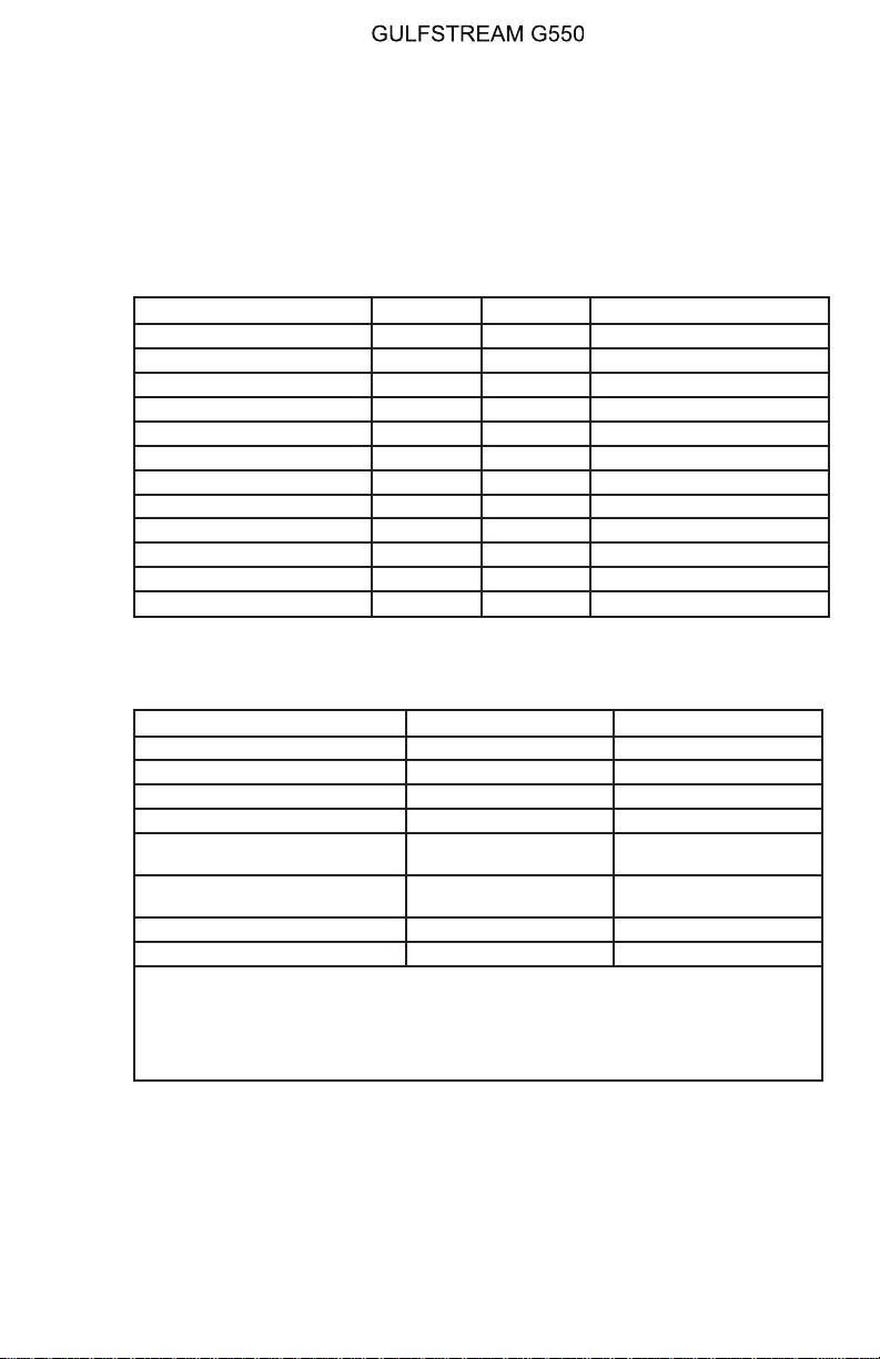
A. Circuit Breakers (CBs):
The following CBs power the MAUs:
Circuit Breaker Name: CB Panel Location: Power Source:
MAU #1A PRI POP A-10 L ESS DC Bus
MAU #1A SEC CPOP A-10 R MAIN DC Bus
MAU #1B PRI CPOP A-9 R ESS DC Bus
MAU #1B SEC POP A-9 L MAIN DC Bus
MAU #2A PRI CPOP A-8 R MAIN DC Bus
MAU #2A SEC POP A-8 L MAIN DC Bus
MAU #2B PRI CPOP A-7 R ESS DC Bus
MAU #2B SEC POP A-7 R MAIN DC Bus
MAU #3A PRI POP A-6 L MAIN DC Bus
MAU #3A SEC CPOP A-6 R MAIN DC Bus
MAU #3B PRI POP A-5 L ESS DC Bus
MAU #3B SEC CPOP A-5 R MAIN DC Bus
B. Crew Alerting System (CAS) Messages:
The following CAS messages are associated with the MAUs:
Area Monitored CAS Message Message Color
AGMs AGM 1-2-3-4 Fail Amber
APMs APM 1-2-3-4 Fail Amber
APMs APM Miscompare Amber
MAU Fans MAU 1-2-3 Fan Fail Amber
MAU MAU 1A-1B-2A-2B-
MAU MAU 1A-1B-2A-2B-
3A-3B OVRHT
3A-3B Fail
Amber
Amber
AGMs AGM 1-2-3-4 Fail Blue
APMs APM 1-2-3-4 Fail Blue
The listed caution messages may be displayed individually or in various
permutations according to the configuration of the malfunction. For instance, MAU
1A-2B-3A OVRHT or MAU 1B-3A-3B Fail might be displayed if conditions warrant.
Because of the extensive number of message combinations possible, only the
representative root messages are included in this tabulation.
NOTE
C. Limitations:
There are no limitations specific to the MAUs as of this writing.
PRODUCTION AIRCRAFT SYSTEMS 2A-31-00
Page 3
July 15/04
OPERATING MANUAL
Title Page
Prev Page
Next Page
TOC
Page 4
July 15/04
MAU #1
Figure 1
PRODUCTION AIRCRAFT SYSTEMS2A-31-00
OPERATING MANUAL
Title Page
Prev Page
Next Page
TOC
MAU #2
Figure 2
PRODUCTION AIRCRAFT SYSTEMS 2A-31-00
Page 5
July 15/04
OPERATING MANUAL
Title Page
Prev Page
Next Page
TOC
Page 6
July 15/04
MAU #3
Figure 3
PRODUCTION AIRCRAFT SYSTEMS2A-31-00

OPERATING MANUAL
Title Page
Prev Page
Next Page
TOC
2A-31-20: Cockpit Clock System
1. General Description:
The cockpit chronometers provide accurate time displays to the flight crew.
2. Description of Subsystems, Units, and Components:
There are two chronometers on the outboard sides of the forward instrument
panel: #1 on the pilot side and #2 on the copilot side. Each is capable of the
following time displays:
• Greenwich Mean Time (GMT)
• Local time (LT)
• Flight time (FT)
• Elapsed time (ET)
Greenwich and local time are displayed in hours and minutes. Flight and elapsed
time is displayed in minutes and seconds. Both are displayed in decimal form. The
flight time display, when selected, records the elapsed time since the weight-onwheels switch transitions from ground to flight mode.
Each chronometer receives power from the essential flight instrument bus, and
has replaceable batteries to ensure operation if aircraft power is interrupted. Each
installation has a two inch digital display containing the microprocessor controlled
chronometer and incandescent lighting. See Figure 4.
3. Controls and Indications:
(See Figure 4.)
A. Circuit Breakers (CBs):
The chronometers are protected by the following circuit breakers (CBs):
Circuit Breaker Name: CB Panel: Location: Power Source:
CLOCK # 1 POP B-4 ESS FLT INST Bus
CLOCK # 2 CPOP B-4 ESS FLT INST Bus
4. Limitations:
There are no limitations established for the cockpit clocks system at the time of
this writing.
PRODUCTION AIRCRAFT SYSTEMS 2A-31-00
Page 7
July 15/04

OPERATING MANUAL
Title Page
Prev Page
Next Page
TOC
Page 8
July 15/04
Cockpit Clocks
Figure 4
PRODUCTION AIRCRAFT SYSTEMS2A-31-00

OPERATING MANUAL
Title Page
Prev Page
Next Page
TOC
2A-31-30: Digital Flight Data Recorder System
1. General Description:
The digital flight data recorder (DFDR) system receives digitized dynamic aircraft
flight environmental data received from the Modular Avionics Units (MAUs). In
addition to the environmental data, the recorder tracks control column, control
wheel forces, and has an accelerometer input. The data is transmitted to the
DFDR and stored in digital memory.The DFDR is located in the tail compartment
aft of the cockpit voice recorder (CVR). See Figure 6.
DFDR operation is limited by integrated relays to record data only when the
aircraft engines are running and the weight-on-wheels (WOW) switches are in the
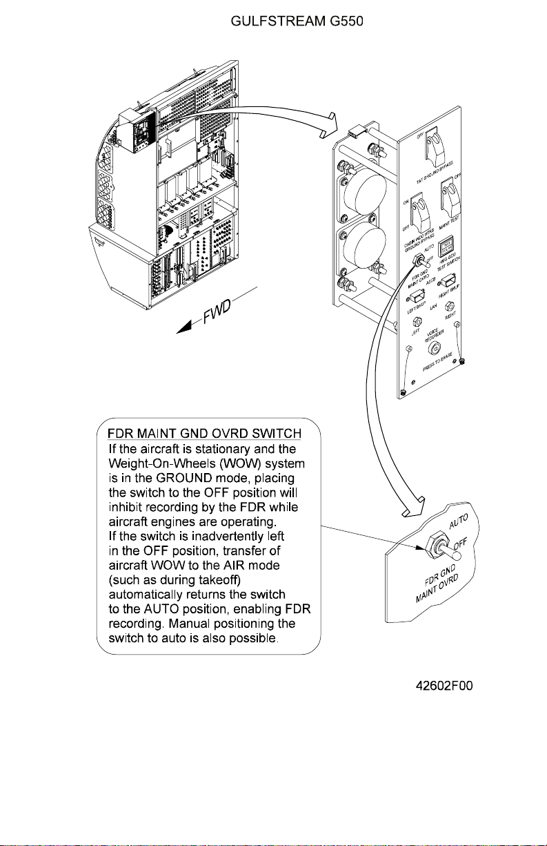
air mode. A maintenance override switch installed on the monitor and test panel
will bypass the engine fuel pressure and WOW relays to allow maintenance on
the DFDR system while the aircraft is static. The switch is illustrated in Figure 5.
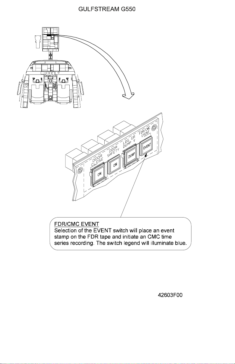
The flight crew may imprint an event stamp on the recorded data in the DFDR to
note a significant instance of flight operations that may warrant subsequent
review, for example, encountering severe air turbulence. The combined DFDR/
CMC EVENT button is located on the cockpit overhead panel above the display
system switching controls as shown in Figure 8.
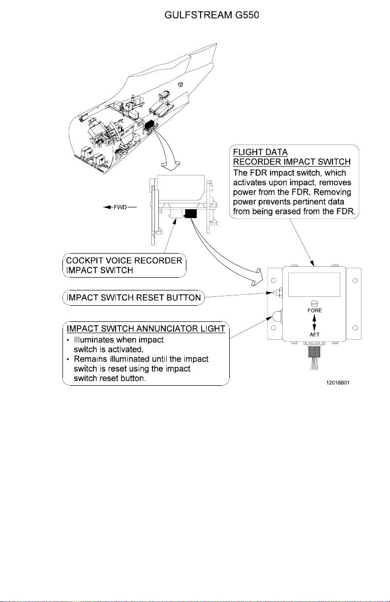
Like the CVR, the DFDR has an impact switch that closes at 2.5 G to stop the
recording process and preserve recorded data. When the impact switch has been
activated, an adjacent indicator light illuminates signalling that the DFDR has
ceased recording. The impact switch may be reset on the ground. See the
illustration in Figure 7.
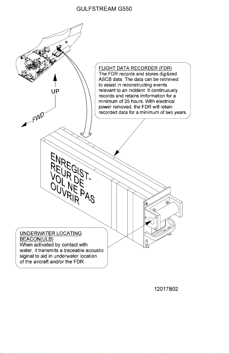
An underwater locator device (see Figure 6) is attached to the DFDR to facilitate
recovering the recorder if the aircraft is lost over water.
2. Description of Subsystems, Units and Components:
A. Digital Flight Data Recorder (FDR):
The DFDR records and stores digitized MAU data. The data can be
retrieved to assist in reconstruction of events relevant to an incident. The
DFDR continuously records a minimum of 25 hours of flight data and
retains data in a crash survivable memory unit (CSMU). With electrical
power removed, recorded data is retained for a minimum of two years. The
DFDR is located in the tail compartment aft of the CVR. It is international
orange in color for high visibility and the attached CSMU has two reflective
stripes.
B. DFDR Impact Switch:
The DFDR impact switch, which activates at an acceleration of 2.5 G,
removes power from the DFDR and preserves the data in the CSMU. The
impact switch is mounted in the tail compartment underneath the CVR
mounting shelf. Activation of the impact switch also causes an annunciator
on the switch housing to illuminate until the impact switch is reset. A reset
switch is located on the switch housing.
C. Underwater Locating Beacon (ULB):
An acoustic underwater locating beacon (ULB) is attached to the DFDR.
When activated by contact with water, it transmits an audible signal to aid
underwater location of the aircraft and/or DFDR. The ULB receives power
from a self-contained battery that has an expected life of six years. The
protective casings of the DFDR and CSMU are designed to protect data
PRODUCTION AIRCRAFT SYSTEMS 2A-31-00
Page 9
July 15/04

OPERATING MANUAL
Title Page
Prev Page
Next Page
TOC
memory to a water depth of twenty thousand (20,000) feet.
D. DFDR Maintenance Ground Override Switch:
The DFDR maintenance ground override switch is located on the Right
Electrical Equipment Rack (REER) on the system monitor test panel, and
is labeled FDR MAINT GRD OVRD. If the aircraft is stationary and the
Weight-On-Wheels (WOW) system is in the GROUND mode, placing the
switch in the OFF position will inhibit recording by the DFDR while aircraft
engines are operating. If the switch is inadvertently left in the OFF position,
transfer of WOW to the AIR mode (such as during takeoff) automatically
returns the switch to the AUTO position, enabling DFDR recording. Manual
positioning the switch to the AUTO position is also possible.
E. DFDR / CMC EVENT Switch:
The FDR / CMC EVENT switch is located on the cockpit overhead panel.
When momentarily depressed, an event stamp is placed on the FDR tape.
When the event switch is depressed, the Central Maintenance Computer
(CMC) saves a data block of information that spans from 30 seconds prior
to switch activation and continues for one minute following release of the
switch. A blue Event Record advisory message is also displayed on the
Crew Alerting System (CAS).
3. Controls and Indications:
(See Figure 5 and Figure 8.)
A. Circuit Breakers (CBs):
The flight data recording system is protected by the following CBs:
Circuit Breaker Name: CB Panel: Location: Power Source:
FDR LEER J-10 L ESS DC Bus
L FORCE SENSORS LEER J-9 #2 ESS AC Bus
R FORCE SENSORS REER E-4 #1 ESS AC Bus
B. Crew Alerting Systems (CAS) Messages:
CAS messages associated with the flight data recording system are:
Area Monitored: CAS Message: Message Color:
DFDR FDR System Fail Blue
FDR/CMC EVENT switch Event Record Blue
4. Limitations:
There are no limitations established for the flight data recording system at the time
of this writing.
PRODUCTION AIRCRAFT SYSTEMS2A-31-00
Page 10
July 15/04
OPERATING MANUAL
Title Page
Prev Page
Next Page
TOC
FDR Maintenance Ground Override Switch
Figure 5
PRODUCTION AIRCRAFT SYSTEMS 2A-31-00
Page 11
July 15/04
OPERATING MANUAL
Title Page
Prev Page
Next Page
TOC
Page 12
July 15/04
Flight Data Recorder (FDR) / Underwater Locating Beacon (ULB)
Figure 6
PRODUCTION AIRCRAFT SYSTEMS2A-31-00
OPERATING MANUAL
Title Page
Prev Page
Next Page
TOC
FDR Impact Switch
Figure 7
PRODUCTION AIRCRAFT SYSTEMS 2A-31-00
Page 13
July 15/04
OPERATING MANUAL
Title Page
Prev Page
Next Page
TOC
Page 14
July 15/04
FDR / CMC EVENT Switch
Figure 8
PRODUCTION AIRCRAFT SYSTEMS2A-31-00
OPERATING MANUAL
Title Page
Prev Page
Next Page
TOC
2A-31-40: Data Management Unit
1. General:
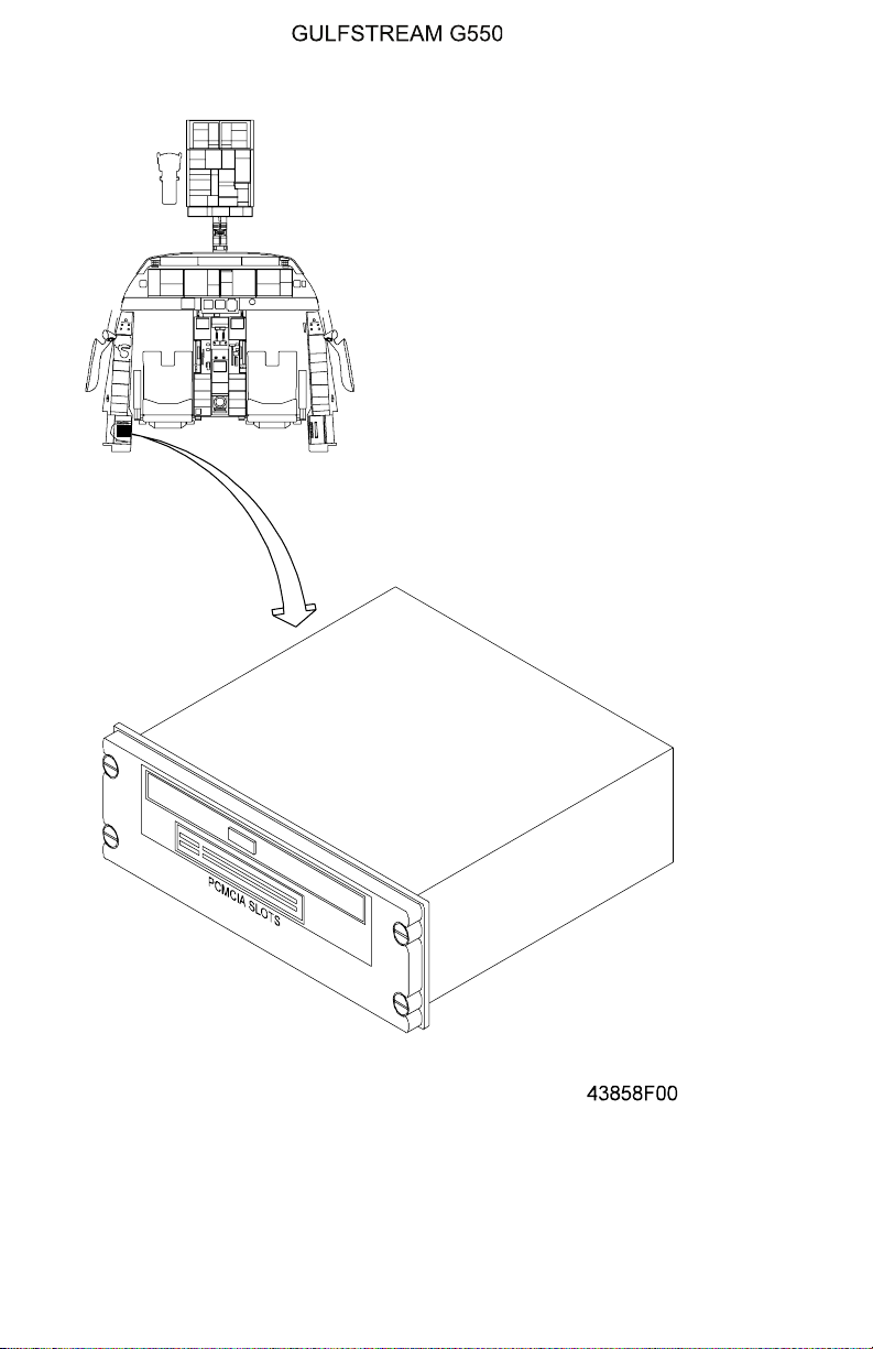
AHoneywellDataManagementUnit(DMU) is installed in the pilot side console for
use in uploading navigation and approach plate data to the Flight Management
Systems (FMS), updating the terrain database in the Enhanced Ground Proximity
Warning System (EGPWS), or for maintenance diagnostics. The DMU is
equipped with a tray accommodating Digital Versatile Discs (DVDs) and two (2)
slots for insertion of type II and type III Personal Computer Memory Card
International Association (PCMCIA) flash memory cards. The DMU is illustrated in
Figure 9.
The DMU communicates with components and systems within the PlaneView
avionics suite over a Local Area Network (LAN) connection, with data exchange
operations controlled with the Multi-function Control and Display Units (MCDUs)
or through a Personal Computer (PC) connected to a sub-D outlet on the Testand
Monitor Panel. The database transfer operations are described in Section 2B-23-
00. If a fault is detected within the DMU, DVD or PCMCIAcard during the transfer
operation, the MCDU(s) will display a message associated with the fault. A list of
DMU fault messages is contained in Section 2B-34-00.
2. Controls and Indications:
A. Circuit Breaker (CB):
The following CB powers the DMU:
Circuit Breaker Name: CB Panel: Location: Power Source:
DMU REER D-5 R MAIN DC Bus
B. Crew Alerting System (CAS) messages:
There are no CAS messages associated with the DMU. See Section
2B-33-00 for MCDU fault messages associated with the DMU and Section
2B-34-00 for a list of DMU fault codes.
3. Limitations:
There are no limitations associated with the DMU as of this writing.
PRODUCTION AIRCRAFT SYSTEMS 2A-31-00
Page 15
July 15/04
OPERATING MANUAL
Title Page
Prev Page
Next Page
TOC
Page 16
July 15/04
Data Management Unit
Figure 9
PRODUCTION AIRCRAFT SYSTEMS2A-31-00

OPERATING MANUAL
Title Page
Prev Page
Next Page
TOC
2A-31-50: Cockpit Printer
1. General:
A Miltope Corporation Model TP4840 dot-matrix thermal printer is installed in the
copilot side console. (See Figure 10.) The printer is interfaced with ARINC-429
bus connections to allow communication with the Mult-function Control and
Display Units (MCDUs) with an additional Local Area Network (LAN) ethernet
connection for data exchange with the Central Maintenance Computer (CMC)
module, or a Personal Computer (PC) connected to sub-D installations on the
CMC module face or the Test and Monitor Panel. The printer may be used to
produce hard copies of approach plates, Notice(s) to Airmen (NOTAMS), weather
information or other operational documents useful to the flight crew.
The printer is capable of producing three hundred (300) characters per second
over the ARINC-429 bus connections or four (4) pages per minute over the LAN
interface. In addition to printing a standard ninety-six (96) character set, the printer
will also reproduce bit-map formats. Printing is accomplished on a continuous roll
of thermal paper eight and one half (8.5) inches wide (216 mm) and one hundred
twenty-five (125) feet (38.1 meters) long. The paper is stored inside the printer
face with the bottom of the faceplate configured to provide a convenient tearing
surface. Paper replenishment is accomplished by opening the faceplate with two
push latches on either side of the printer.
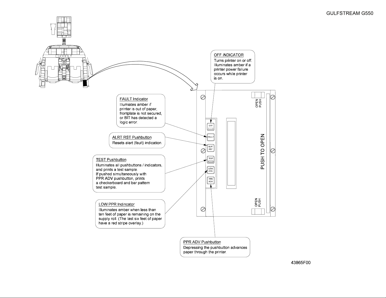
2. Controls and Indications:
A. Printer Indications:
Ahorizontal row of indicators / pushbuttons is installed on the upper face of
the printer. The legends within the indicators / pushbuttons are arranged
vertically and may require the operating crew member to view the text
sideways. The indicators and associated actions are:
• OFF - selects the printer on or off. Illuminates amber when printer
power is on and printer is selected off or if a power fault occurs with
printer selected on
• FAULT - illuminates amber if printer is out of paper, the printer
faceplate is not secured closed, or the Built-In-Test (BIT) function
has detected a fault. (The printer automatically performs a BIT
whenever the printer is selected ON).
• ALRT RST - resets the alert (fault) function
• TEST - illuminates all of the indicators on the faceplate, performs a
BIT test and prints a test sample. (NOTE: pressing the TEST and
PPR ADV pushbuttons simultaneously will print a checkerboard and
solid bar pattern sample.)
• LOW PPR - illuminates amber when only ten (10) feet (3.04 meters)
of paper are remaining on the supply roll. The last six (6) feet (1.8
meters) of paper remaining are indicated by a red stripe.
• PPR ADV - advances the paper through the printer
B. Circuit Breaker (CB):
The following CB powers the cockpit printer:
Circuit Breaker Name: CB Panel: Location: Power Source:
COCKPIT PRINTER REER C-5 R MAIN DC Bus
PRODUCTION AIRCRAFT SYSTEMS 2A-31-00
Page 17
July 15/04

OPERATING MANUAL
Title Page
Prev Page
Next Page
TOC
C. Crew Alerting System (CAS) Messages:
There are no CAS messages associated with the cockpit printer.
D. Limitations:
There are no limitations applicable to the cockpit printer as of this writing.
Page 18
July 15/04
PRODUCTION AIRCRAFT SYSTEMS2A-31-00
OPERATING MANUAL
Title Page
Prev Page
Next Page
TOC
Cockpit Printer
Figure 10
2A-31-00
Page 19 / 20
July 15/04
 Loading...