

Gulfstream Aerospace AA-58 TIGER 1977, AA-58 TIGER 1978, AA-58 TIGER 1979 Pilot Operating Handbook
'
PILOTS OPERATING HANDBOOK
~II
Gulfstrea1n
Aerospace
Model
AA-58
TIGER
1977I1978/
1979
THIS HANDBOOK INCLUDES THE
MATERIAL
REQUIRED
TO
BE
FUR·
NISHED TO THE
PILOT
BY
FAR PART 23.
REGISTRATION NO.
GULFSTREAM AEROSPACE CORPORATION
SAVANNAH, GEORGIA, U.S.A.
©
Issued:
September
30,
1976
Revision
4,
Revised
May
12,
1983
0
Copyrishl
1979
All
ri~J1h
rNntd.
induding
lht
rig.Ill to
rqm><lun~·
1hi~
puhlicalion
No parl
m~y
t>e
rtprn·
ducffi.
~lured
m ;iny
rc-lntnl
.\y.\ttm.
or
lnn\mllh'd
many
parlor
funn
or
hy
any
me-an~.
r~clronic
pholocopyin11-.
microfilm,
microfid1e, nu·chan1cal.
or
olhrrwL'il".
without
prior
wn41tn
[>t'ffiU\~Hln
of
C.ul(slrcam
Amcnr~11

GULFSTREAM AEROSPACE
MODEL
AA-5B TIGER
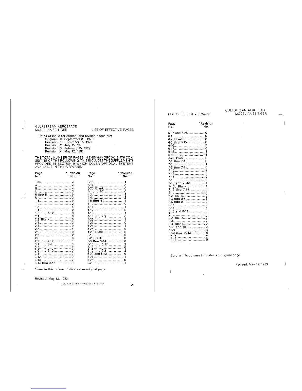
LIST OF EFFECTIVE PAGES
Dates
of
issue for original
and
revised
pages
are:
Original.
...
O ... September
30,
1976
Revision
...
1.
..
December
15, 1977
Revision
... 2 ...
July
15,
1978
Revision
...
3 ... February 15, 1979
Revision
... 4 ...
May
12,
1983
THE TOTAL NUMBER OF PAGES
IN
THIS HANDBOOK
IS
176 CON-
SISTING
OF
THE FOLLOWING. THIS INCLUDES THE SUPPLEMENTS
PROVIDED IN SECTION
9 WHICH COVER OPTIONAL SYSTEMS
AVAILABLE
IN
THE AIRPLANE.
Page
No.
*Revision
No.
Title A ............................. 4
B ............... .
..
4
.
..
4
i............
................
3
ii
thru iii .......................... O
iv.. . ................. .
...
3
.0
.2
......
4
...
2
.0
....
0
0
1-1
....................... .
1-2
........... .
1-3
..
1-4
.................... .
1-5
thru 1-12
2-1
........................ .
2-2
Blank
2-3
.....
········ 3
..
0
2-4
..
2-5
2-6.
2-7.
................... 4
......... 0
2-8
......
..
......
2
0
..
1
..
0
2-9
thru
2-12
.............
..
3-1
thru
3-4
...
..
35
......
3-6
thru 3-10
..
3-11
..
3-12
..
3-13 ....... .
3-14 thru 3-17.
......... 2
...... 0
........ 2
..
0
....
2
..........
0
Page
No.
•Revision
No.
3-18. . .... 1
3-19 ...
0
3-20 Blank
........... 0
4-1
and 4-2....
..
.... 0
4-3.................. . .......... 3
4-4............... . .... 2
4-5
thru
4-9..
..
............. 1
4-10
.................................. 0
4-11
.................................... 1
4-12
..................................
,_
0
4-13
.................................... 1
4-14
thru 4-21.. ................. 0
4-22
.................................... 1
4-23... .
0
4-24
................................... 1
4-25
.................................... 0
4-26
Blank.... . .. 0
5-1. ...............
..
... 0
5-2
Blank.... . . 0
5-3
thru
5-14
................... _ O
5-15 thru
5-17
. 2
5-18.......... .
0
5-19 thru
5-21..
. .. 2
5-22 and
5-23..
. O
5-24
.................................. 1
5-25....
..
0
5-26
......
··························- 1
·zero
in
this
column
indicates
an original page.
Revised: May
12,
1983
198]
Gulfs1reilm
Aprospacr
Corporation
A
LIST OF EFFECTIVE PAGES
Page
No.
"Revision
No.
5-27 and 5-28.....
..
0
6-1.. ................ 0
6-2
Blank ................ 0
6-3
thru 6-15.... . .......... O
6-16......................
..
..... 3
6-17 ...................................
0
6-18 ................................... 1
619
.................................... 1
6-20
Blank
....................... 0
7-1
thru
7-4
....................... 0
~5...........
. ......... 1
7-6
thru 7-11.
..
...... 0
7-12.......... 2
7-13 .................................... 4
7-14 .................................. 2
7-15 ................... -
""'""
0
7-16
and 7-16a ................. 1
7-16b Blank......... 1
7-17
thru
7-24.............. 0
~1
..
--·······--·-·--·-
.0
8-2
Blank..................
...
0
8-3
thru 8-5................ . 3
8-6
thru 8-10............. .
...
0
8-11
......... ·-..................... - 2
8-12.. . ........................ 1
8-13 and 8-14 ....................
O
9-1... ..................
..
....
0
9-2
Blank........... . ....... 0
9-3......................
..
........ a
9-4
Blank..
..
..... 0
10-1
and
10-2
.................... 0
10-3
........................ , ........... 3
10-4
thru 10-14 ................ 0
10-15
........................ "
""
2
10-16 ................................ 0
GULFSTREAM AEROSPACE
MODEL
AA-5B TIGER
·zero
in
this
column
indicates
an
original
page
.
Revised: May
12,
1983
B
GULFSTREAM
AMERICAN
MODEL
AA~58
TIGER
WELCOME
ABOARD!
WELCOME
ABOARD
y r AA-58
Tiger
has
been
designed
and
constructe?
to
provide
'fOU
wi_th
a
re~~onsive
four-place
airplane
to
serve
your
needs
for
either pleasure
or
business
flying in
both
comfort
and
economy.
This handbook has been prepared
to
.help you obtain the
maxi~um
P
!easu_re
a_nd
utility
from
your
airplane.
Read
it
carefully,
review
it
frequently,
and
keep
it
w1tl1
you
in
the
airplane
at
all
times.
With proper operational techniques and good maintenance, your
G~lfstr;arn
I
American Tiger should serve you well.
Get
to
know
your
Gulfs~ream
mencan
Dealer.
He
is
equipped
to
provide
any
assistance
that
may
be
required.
Revised:
February
15,
1979
PERFORMANCE~
SPECIFICATIONS
GULFSTREAM
AMERICAN
MODEL
AA~5B
Tl
GER
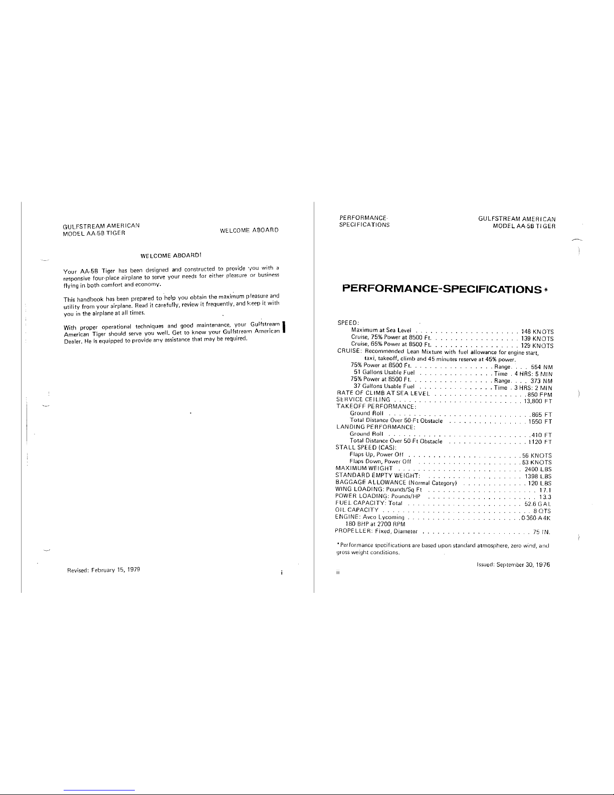
PERFORMANCE-SPECIFICATIONS*
SPEED:
Maximum
at
Sea
Level
148
KNOTS
Cruise,
75%
Power
at
8500
Ft.
139
KNOTS
Cruise, 65% Power at 8500 Ft. 128
KNOTS
CRUISE:
Recommended
Lean
Mixture
with fuel
allowance
for
engine start,
taxi, takeoff,
climb
and
45
minutes
reserve
at
45%
power.
75% Power at
8500
Ft. . . Range. 554 NM
51
Gallons
Usable
Fuel
. Time . 4
HRS:
5
~.11/N
75% Power at 8500 Ft. . Range. . . 373
NM
37 Gallons Usable
Fuel
. Time . 3
HRS:
2
~.lllN
RATEOFCLIMBATSEALEVEL
.B50FPM
SEHVICE
CEILING
. . 13,800
FT
TAKEOFF
PERFORMANCE:
Ground
Roll
Total
Distance
Over
50-Ft
Obstacle
LANDING
PERFORMANCE:
Ground
Roll
Total
Distance
Over
50-Ft
Obstacle
STALL
SPEED (CASI:
Flaps
Up,
Power
Off
.
Flaps
Down,
Power
Off
MAXIMUM
WEIGHT
STANDARD
EMPTY
WEIGHT:
BAGGAGE
ALLOWANCE
(Normal Category)
WING
LOADING:
Pounds/Sq Ft
POWER
LOADING:
Pounds/HP
FUEL
CAPACITY:
Total
01 L CAPACITY
ENGINE:
Avco Lycoming
180 BHP at 2700
RPM
PROPELLER: Fixed, Diarneter
.865
FT
.
1550
FT
.410
FT
. 1120
FT
.
56
KNOTS
. 53
KNOTS
2400
LBS
139B
LBS
.120LBS
17.1
13.3
52.6GAL
BOTS
.0360A4K
75
IN.
•Performance S[lecifications
are
based
upon
standard
atmosrhere,
zero
wind,
and
gross
weight
conditions.
Issued:
September
30,
1976
II
GULFSTREAM
AMERICAN
MODEL
AA5B
TIGER
TABLE
OF
CONTENTS
TABLE
OF
CONTENTS
GENERAL
LIMITATIONS
EMERGENCY
PROCEDURES
NORMAL
PROCEDURES
PERFORMANCE
...
WEIGHT & BALANCE/
EQUIPMENT
LIST
AIRPLANE
& SYSTEMS DESCRIPTION
AIRPLANE
HANDLING,
SERVICE &
MAINTENANCE
SUPPLEMENTS
(Optional
Systcrns Description
& Operating Procedures)
SAFETY
INFORMATION
Issued:
September
30,
1976
SECTION
. 1
,2
.3
. 4
.5
.6
. 7
. '
'8
g
10
iii
WARRANTY
GULFSTREAM
AMER
CAN
MODEL
AA-58
Tl
GER
GULFSTREAM
AMERICAN
CORPORATION
(herein
GULFSTREAM
At~ER
ICAN) warrants each new aircraft and part
thereof
manufactured by
it,
tog~ther
with
all
new
aircraft
equipnient
and
accessories
bearing
the
name
"G
JLF-
STREAM
AMERICAN,"
to
be free
from
defects in material and
workmanship
under
normal
use
and
service,
but
extends
no
warranty
o~
any
kind,
express~d
or
implled,
to
any items
not
manufactured
by
GULFSTREAM
AMERICAN,
or
not
so
bearin-g
its
name,
whether
incorporated
into
or
installed
in
the
aircraft,
except
that
the
workmanship involved
in
installing suct1 items
is
warranted to be
without
defect.
The
obligation
of
GULFSTREAM AMERICAN under this
warranty
is
limited
to
replacement
or
repair,
at
the
option
of GULFSTREAM AMERICAN,
of any such aircraft,
or
any
part
or accessory which shall within
six
(6)
months
(twelve (12)
months
on
1978
and subsequent models) of operation be
found
defective. Such aircraft, part
or
accessory
is
to be returned to a
GU
LFSTA ::AM
AMERICAN
DEALER
upon
which examination by GULFSTREAM AMERICAN,
shall disclose
to its reasonable satisfaction to
lwve
been thus defective. This war-
ranty shall
not
in
any way
apply
to
or
cover any products which are
in
GULF-
STREAM AMERICAN's
opinion
damaged
as
a result of being
in
any
manner
altered
or
repaired
outside
of
the
factory of GULFSTREAM AMERICAN or
that
shall have been subject to misuse or negligence.
GULFSTREAM AMERICAN
makes no
warranty
whatsoever with respect to
engines, radios,
propellers, ignition appar<1tus, starting devices,
~enerators,
bat-
teries,
or
other
trade
accessories, inasmuch
as
such products are generally war-
ranted separately by their respective manufocturers .
"THESE
WARRANTY
PROVISIONS ARE EXPRESSLY IN LIEU OF
ALL
OTHER
WARRANTIES,
EXPRESSED,
STATUTORY
OR
IMPLIED
IN
FACT
OR
BY
LAW,
INCLUDING
ANY
IMPLIED
WARRANTY
OF
MERCHANT·
ABILITY
OR FITNESS FOR A
PARTICULAR
PURPOSE,
AND
OF
ANY
OTHER
OBLIGATION
OR
LIABILITY
ON
Ti!E
PART
OF
GULFSTREAM
AMERICAN,
EXPRESSED
OR
IMPLIED,
OF
A~Y
NATURE
WHATSOEVER
.
GULFSTREAM
AMERICAN
NEITHER
ASSUMES NOR
AUTHORIZES
ANY
OTHER
PERSON OR BUSINESS
ORGANIZATION
TO
ASSUME FOR
IT
ANY
OTHER
WARRANTY
OR
LIABILITY
IN
CONNECTION
WITH
THE
SALE,
USE
OR
OPERATION
OF ITS PRODUCTS."
IMMEDIATELY
ON
COMMENCING
FIRST
USE
OF
AN
AIRCRAFT, A WAR-
RANTY
VALIDATION
CARD
MUST
BE
FILLED
OUT
AND
MAILED
TO
THE
ATTENTION
OF THE CUSTOMER SERVICE
MANAGER,
COMMERCIAL
LIGHT
AIRCRAFT,
P.O.
BOX
2206,
SAVANNAH,
GEORGIA,
31402. NO
WARRANTY
CLAIMS
WILL
BE
HONORED
IF
THIS
CARD
IS
NOT ON
FILE
AT
THE
FACTORY.
iv
Revised: Feilnwry 15,
1979
GULFSTREAM AMERICAN
MODEL
AA
58 TIGER
TABLE
OF CONTENTS
Three
View
..
Introduction
..
Descriptive Data
Engine .
Propeller
Fuel
..
Oil
...
SECTION
1
GENERAL
Maximum
Certificated
Weights
Standard
Airplane
Weights
Cabin
and
Entry
Dimensions
Baggage
Space and Entry Dimensions
Specific Loadings . ,
..
Symbols, Abbreviations and Terminology
General Airspeed Terminology and Symbols
Meteorological
Terminology
.......
.
Engine
Power
Terminology
. ,
....
, . . .
..
Airplane
Performance
anrl
Flight
Planning
Terminology
Weight and Balance
Terminology
....•..
Issued: September 30, 1976
SECTION 1
GENERAL
Page
. 1·2
. 1·3
. 1·3
. 1·3
. 1·3
.
1-4
. 1-4
. 1 8
. 1
·9
. 1·9
. 1·9
. 1·9
. 1·9
. 1·9
1·10
1-10
1.11
1-11
1-1
SECTION 1
GENERAL
9
....
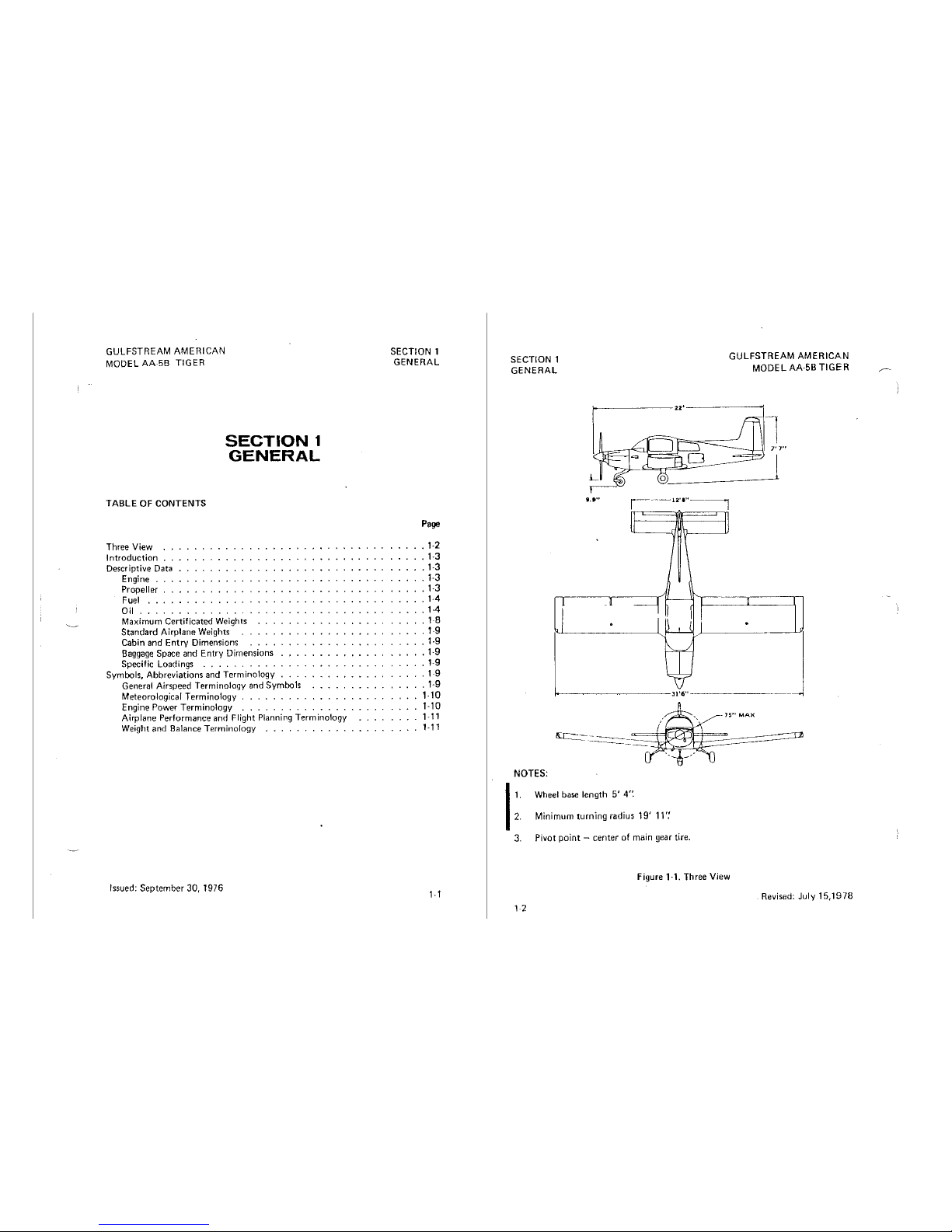
NOTES:
1
1.
2.
Wheel base
length
5'
4•:
Minimum turning radius 19' 11·;
3.
Pivot
point -center
of
main
gear tire.
GULFSTREAM AMERICAN
MODEL AA·5B
TIGER
_J
figure
1-1.
Three
View
Revised: July 15,1978
1 2
GULFSTREAM AEROSPACE
MODEL
AA58
TIGER
INTRODUCTION
SECTION
1
G'CNERAL
The ten
sections
of
this
handbook
contain
the
Information
needed
by
the
pilot
for
safe
and
efficient
operation
of
the
Gulfstream
Aerospace Model
AA·58 airplanes.
This
handbook
also
includes
the material
required
to
be
furnished
to the
pilol
by FAR, Part
23,
and
supplemen\al
data
covering
Gulfstream
Aerospace designed
optional
equipment installed in the airplane.
Section 1 provides basic data and
information
of
general Interest to
the
pilot,
to
assist
him in loading, sheltering, handling, and routine
prefllgr.t
check-
ing
of
the airplane.
Also
Included In
this
section
are
definitions
and explana-
tions
of
the
symbols,
abbreviations
and
termlnology
used
In
this
handbook.
DESCRIPTIVE DATA
ENGINE
NOTE
Unless
otherwise
noted,
a!1
per-
formance and operational
data
in
this book are based on sea
level,
standard day, and airplane
gross
weight
conditions.
Number
of Engines:
Manufacturer:
Avco
Lycoming
Model
Number: 0-360-A4K
Type: Normally-aspirated, direct-drive, air-cooled, horizonta!!y-opposed,
carburetor
equipped, four-cylinder engine
with
360
cubic
inch
displacement.
Horsepower
Rating and
Engine
Speed:
180
HP at
2700
RPM
PROPELLER
Manufacturer:
McCauley
Model
Number: 1A170/FFA 7563, 1A 170/KFA 7563 or
1A
170EIKFA 7563
Diameter: 75 inches
Type: Fixed
pitch
Revised: May
12,
1983
1·3
(0
1CJfl3
Gulfslwarn
Aerospace
Corpor;il1on
SECTION 1
GENERAL
GULFSTREAM
AME '11CAN
MODEL
AA·5B
TIGER
FUEL
CAUTION
UNDER
NO
CIRCUMSTANCES
SHOULD
FUEL
OF
A LOWER
OC.
TANE
RATING
THAN
THAT
SPECI·
FIED
BELOW,
OR
AUTOMOTIVE
FUEL
(REGARDLESS
OF
OCTANE)
BE
USED.
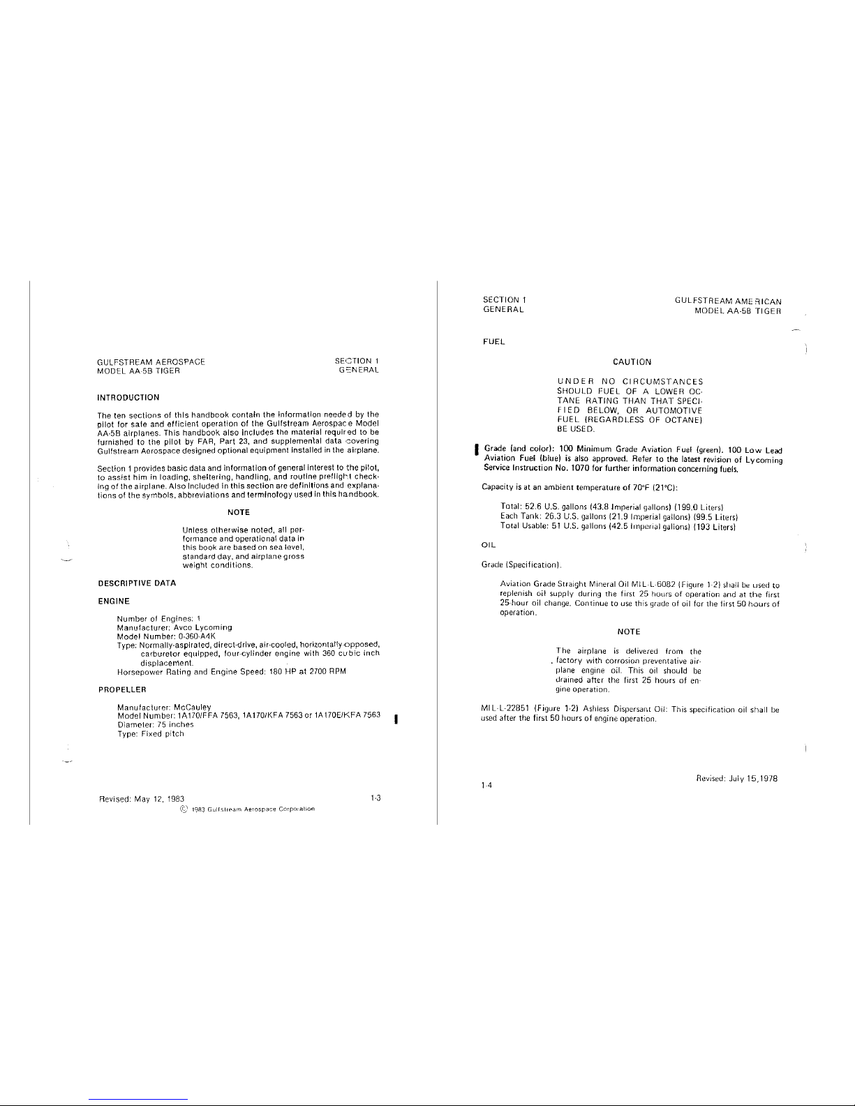
I Grade (and
color):
100
Minimum
Grade Aviation Fuel (green). 100
Low
Lead
Avia_tion
Fuel (.blue)
is
also approved. Refer
to
the latest revision
of
Lycoming
Service
Instruction
No. 1070
for
further
information
concerning fuels.
Capacity
is
at
an
ambient temperature
of
70°F (21°C):
OIL
Total: 52.6 U.S. gallons (43.8 Imperial gallons) (199.0 Liters)
Each
Tank: 26.3
U.S.
gallons (21.9 Imperial gallons) (99.5 Liters)
Total Usable:
51
U.S.
gallons (42.5 lrnpcrial gallons) (193 Liters)
Grade (Specification).
Aviation Grade Straight
Mineral Oil
Ml
L-L-6082 (Figure 1-2) shall
be
used to
replenish oil supply during the first 25 hours
of
operation and at
the
first
25-hour
oil
change. Continue
to
use
this grade
of
oil for the first 50
hours
of
operation.
NOTE
The
airplane
is
de(ivered
from
the
.
factory
with
corrosion preventative air-
plane
engine oil. This oil should
be
Urained after the first 25 hours
of
en-
gine operation.
Ml L-L·22851
~Figure
1-2)
Ast1less
Dispersant Oil: This specification oil shall
be
used
after the
first
50 hours
of
engine operation.
1 4
Revised: July 15, 1978
GULFSTREAM
AMERICAN
MODEL
AA-58
TIGER
TRADE
NAME
MIL-G-21164
GREASE (Note
1)
Aeroshell Grease
17
Braycote
664
PED 3350
Grease
Royea
64
Grease
TG-4727
Grease
MIL-G-6711
GRAPHITE (Note 1)
Graphite
Graphite
Graphite
SECTION 1
GENERAL
MANUFACTURER
Shell Oil Company
Bray
Oil
Company
Standard
Oil
Company
Royal
Lubricants
Company
Texaco
1nc.
Dixon
Company
Electrofilm
Company
Electro-Graph Company
MIL-H-5606
HYDRAULIC
FLUID
(Note 1)
3125
HVD
Oil
Humble
Oil
& Refining
Company
Brayco
Micronic
756C
Bray Oil
Company
PED-3337, -3335
Standard
Oil
Company
Royco
756A
& 8
Royal Lubricants
Company
XSL 7828
Shell
Oil
Company
YT-283
Union
Carbide
VV-P-236
PETROLATUM
(Note 1)
Braycote 236
Bray Oil
Company
Parma
70
Humble
Oil & Refining
Company
Royea
1 R
Royal Lubricants
Company
MIL-L-7870
OIL
(Note
1)
Brayco 363
Bray
Oil
Company
Cosmolube 263
E.
F.
Houghton Company
Enco Instrument
Oil
Humble
Oil
& Refining
Company
Low
Temperature Oi!
1692
Texaco
Inc.
Royco
363
Royal
Lubricants
Company
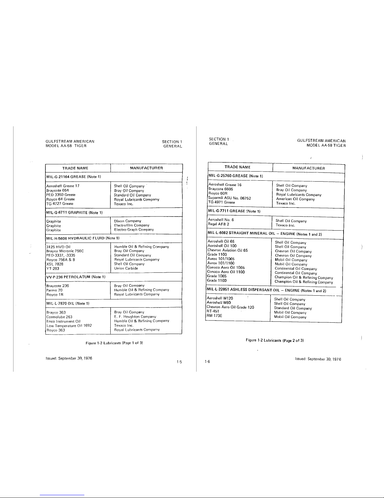
Figure 1-2
Lubricants
(Page 1
of
3)
Issued:
September
30,
1976
1 5
SECTION 1
GENERAL
TRADE
NAME
MIL-G-25760 GREASE (Note
1)
Aeroshell Grease
16
Braycote
6605
Royea
60R
Supermil ASU No. 06752
TG-4971 Grease
MIL-G-7711 GREASE
!Note
1)
Aeroshell No. 6
Regal
AFB 2
GULFSTREAM
AMERICAN
MODEL AA-58
TIGER
MANUFACTURER
Shell Oil
Company
Bray Oil
Company
Royal
Lubricants
Company
American
Oil
Company
Texaco
Inc.
Shell Oil
Company
Texaco
Inc.
MIL-L-6082
STRAIGHT
MINERAL
OIL
- ENGINE (Notes 1
and
2)
Aeroshell Oil
65
Shell Oil
Company
Aeroshell Oil
100
Shell Oil
Company
Chevron
Aviation
Oil
65
Chevron Oil
Company
Grade
1100
Chevron Oil
Company
Avrex
101/1065
Mobil Oil
Company
Avrex
101/1100
Mobil Oil
Company
Conoco
Aero
Oil
1065
Continental
Oil
Company
Conoco
Aero
Oil
1100
Continental
Oil
Company
Grade 1065
Champion
Oil & Refining
Company
Grade 1100
Champion
Oil & Refining
Company
MIL-L-22851 ASHLESS DISPERSANT
OIL
- ENGINE (Notes 1
and
2)
-
-
Aeroshell W120
Shell Oil
Conlpany
Aeroshell W80
Shell Oil
Company
Chevron
Aero
Oil
Grade
120
Standard
Oil
Company
RT-451
Mobil Oil
Company
RM-173E
Mobil
Oil
Company
Figure 1-2
Lubricants
(Page 2
of
3)
Issued:
September
30,
1976
GULFSTREAM
AMERICAN
MODEL AA-5B Tl
GER
TRADE NAME
SECTION 1
GENERAL
MANUFACTURER
MIL-L-22851 ASHLESS DISPERSANT
OIL
- ENGINE (Notes 1
and
2)
(Cont.)
RM-180E
Mobil
Oil Company
TX-6309
Texaco
Inc.
Premium
AD
120
Texaco
Inc.
Premium
AD
80
Texaco
Inc.
Oil E-120
Exxon
Company
Oil A-100
Exxon
Cornpany
Oil E-80
Exxon
Company
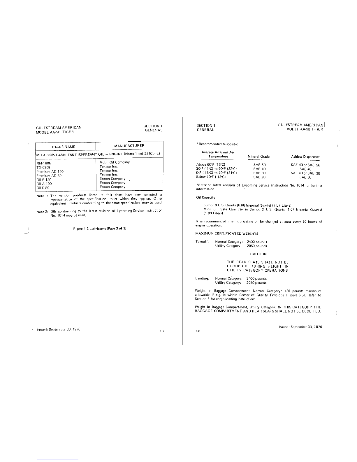
Note 1:
The
vendor
rroducts listed
in
this
chart
have been
selected
as
representative
of
the
specificntion
under
which they
appear.
Other
equivalent
rroducts
conforming
to
the same specification
may
be used.
Note
2: Oils
conforming
to
the
latest revision
of
Lycoming Service
Instruction
No.
1014
may
be
used.
Figure
1·2 Lubricants (Page 3 of 3)
Issued:
September
30, 1976
1-
7
SECTION 1
GENERAL
•Recommended
Viscosity;
Average
Ambient
Air
Temperature
Above 6(l"F (16"C)
30'F
(-1"C)
to
90'F
(32°CJ
O'F
(-18"C)
to
70'F (21"C)
Below
1
O'F
(-1
:?°C)
Mineral Grade
SAE 50
SAE
40
SAE
30
SAE
20
GULFSTREAM
AMERICAN
I
MODEL AA-5B
Tl
GER
Ashless
Dispersant
SAE
40
or
SAE
50
SAE
40
SAE
40 or
SAE
30
SAE
30
*Refer
to
latest
revision
of
Lycoming Service
Instruction
No.
1014
for
further
information.
Oil
Capacity
Sump:
8 U.S.
Quarts
(6.66
Imperial
Quarts)
(7.57
Liters)
Minimum
Safe
Quantity
in
Sump:
2 U.S.
Quarts
(1.67 Imperial
Quarts)
I 1.B9
liters)
It
is
recommended
that
lubricating oil
be
changed
at
least every
50
hours
of
engine
operation.
MAXIMUM
CERTIFICATED
WEIGHTS
Takeoff:
Landing:
Normal
Category:
Utility
Category:
2400
pounds
2050
pounds
CAUTION
THE REAR SEATS
SHALL
NOT
BE
OCCUPIED
DURING
FLIGHT
IN
UTILITY
CATEGORY OPERATIONS.
Normal
ca"tegory:
Utility
Category:
2400
pounds
2050
pounds
Weiylit
in
Baggage
Compartment,
Normal
Category:
120
pounds
maximum
allowable
if
e.g.
is
within
Center
of
Gravity Envelope (Figure 6·5).
Refer
to
Section
6 for cargo
!oading
instructions.
Weight in Baggage
Compartment,
Utility
Category:
IN
THIS
CATEGORY
THE
BAGGAGE COMPARTMENT AND REAR SEATS
SHALL
NOT
BE
OCCUPIED.
Issued:
September
30,
1976
1-8
GULFSTREAM
AMERICAN
MODEL
AA-SB
TIGER
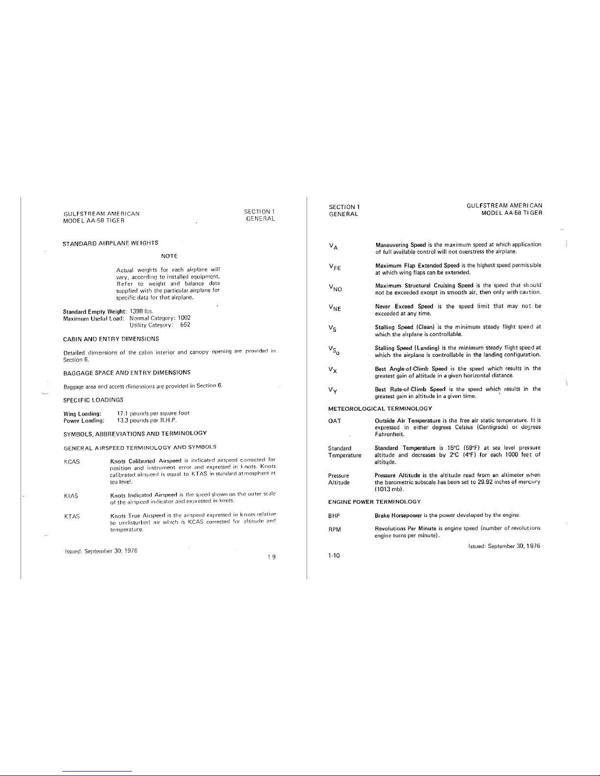
STANDARD
AIRPLANE
WEIGHTS
NOTE
Actual weights for each
airpl<:ine
wil!
vary, accordi11a
to
installed erpiipmcnt.
Refer
to weight and b<llance data
supplied
with
the
particular
airplnne
for
specific
<lata
for
that
airplane.
Standard
Empty
Weight: 1398 lbs.
Maximum Useful Load: Normal Catefjory: 1002
Utility
C<1te~1ory:
652
CABIN
AND
ENTRY
DIMENSIONS
SECTION 1
GENEnAL
Detailed
dirnensions
of
the
cabin
interior
and
canopy
opening
are
rrovirled
in
Section 6.
BAGGAGE
SPACE
AND
ENTRY
DIMENSIONS
B<iggage
area
and
access
dimensions
are
provided
in
Section
6.
SPECIFIC
LOADINGS
Wing
Loading:
Power Looding:
17
.1
pounds
per
square
foot
13.3 pounds per B.H.P.
SYMBOLS,
ABBREVIATIONS
AND
TERMINOLOGY
GENERAL
AIRSPEED
TERMINOLOGY
AND
SYMBOLS
KCAS
Kll\S
KTl\S
Knots
Calibre1ted Airspeed
is
indicated
airspeed
corrected
for
rosition
and
i11strurnent
error
and
expressed in
~nots.
Knots
calibrated
airspeed
is
equal
to
KTAS
in
standard
atmosphere
;:it
sea level.
Knots
Indicated
Airspeed
is
tile speed sfiown on
the
outer
sc;ile
of
the
oirspecd
indicator
<1nd
expressed
in
knots.
Knots
True Airspeed
is
the
<rirspced expressed
in
knots
relotive
to
undisturlird
;:iir
which
is
KCAS
corrected
for altitudP. anrl
temperature.
!ssur.d: Septcrnlir.r 30, 1976
1 g
SECTION 1
GENERAL
Vy
GULFSTREAM
AMERICAN
MODEL
AA-58
Tl
GER
Maneuvering Speed
is
the
maximum
speed
at
which
application
of
full available
control
will
not
overstress
the
airplane.
Maximum Flap Extended Speed
is
the
highest speed permissible
at
which wing flaps can be
extended.
Maximum
Structural
Cruising
Speed
is
the
speed
that
should
not
be
exceeded
except
in
smooth
air,
then
only with
caution.
Never Exceed Speed
is
the
speed limit
that
may
not
be
exceeded at
any
time.
Stalling Speed (Clean)
·is
the
minimum
steady flight
speed
at
which
the
airplane
is
controllable.
Stalling Speed (Landing)
is
the
minimum
steady flight
speed
at
which
the
airplane
is
controllable
in
the
landing configuration.
Best
Angle·of-Climb Speed
is
the
speed which results
in
the
greatest gain
of
altitude
in
a given horizontal distance.
Best
Rate-of·Climb Speed
is
the
speed which results
in
the
greatest gain
in
altitude
in
a given time.
METEOROLOGICAL
TERMINOLOGY
OAT
Standard
Temperature
Pressure
Altitude
Outside
Air
Temperature
is
the
free air
static
temperature. It
is
expressed
in
either
degrees Celsius (Centigrade)
or
degrees
Fahrenheit,
Standard
Temperature
is
15°C (59"F)
at
sea level pressure
altitude
and
decreases
by
2°C
(4°F) for each 1000
feet
of
altitLtde.
Pressure
Altitude
is
the
altitude
read
from
an altimeter
when
the
barometric
subscale has been set
to
29.92 inches
of
mercury
(1013
mb).
ENGINE
POWER
TERMINOLOGY
BHP
RPM
1-10
Brake Horsepower
is
the
power
developed by
the
engine.
Revolutions Per Minute
is
engine speed (number of revolutions
engine turns per minute).
Issued: September 30,
1976
GULFSTREAM
AMERICAN
MODEL
Ak5B
TIGER
SECTION 1
GENERAL
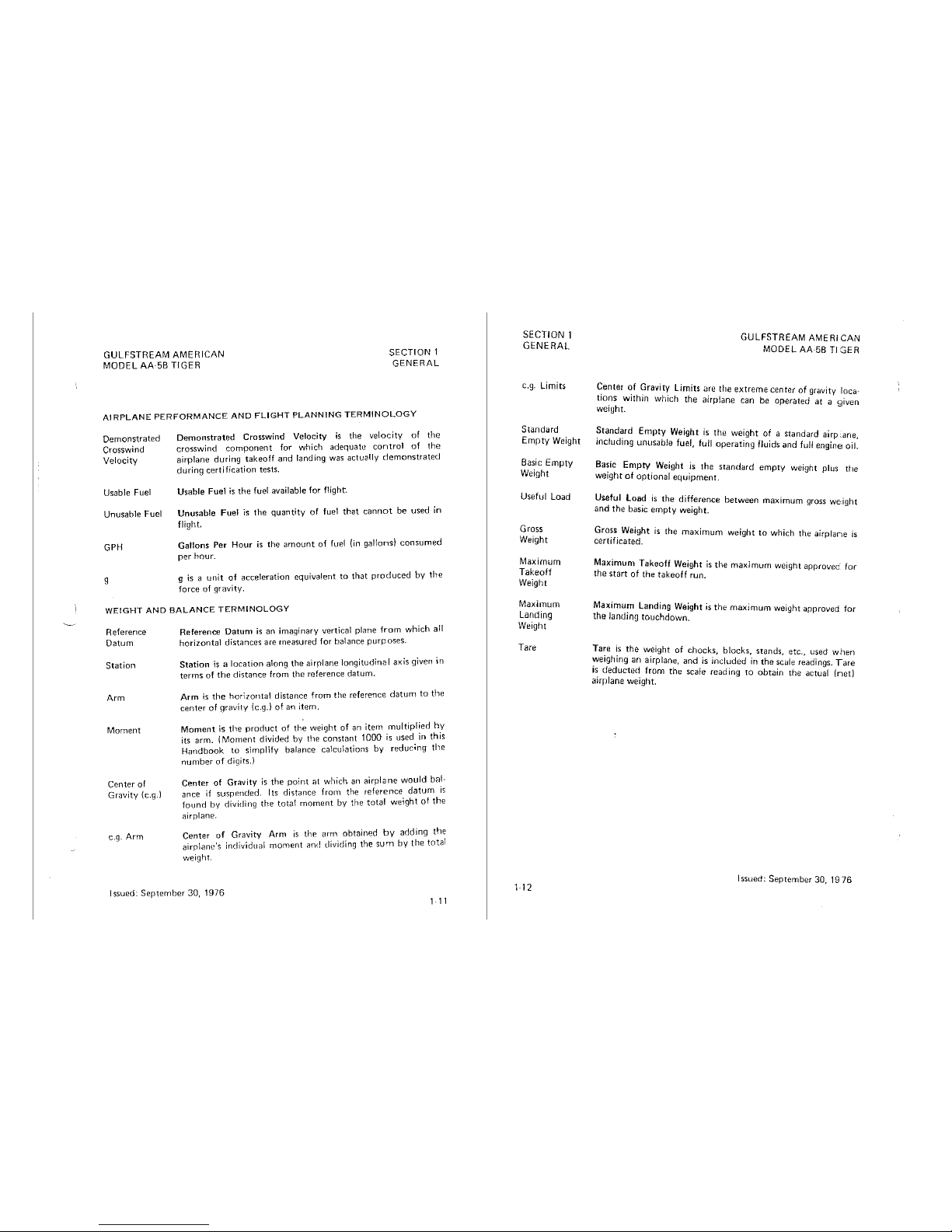
AIRPLANE
PERFORMANCE
AND
FLIGHT
PLANNING
TERMINOLOGY
Demonstrated
Crosswind
Velocity
Usable
Fuel
Unusable Fuel
GPH
g
Demonstrated
Crosswind Velocity
is
the velocity of
the
crosswind
component
for
which
adequat11
control
of
the
airplane
during
takeoff
and
landing
was
actually
demonstrated
during
certification
tests.
Usable
Fuel
is
the
fuel available
for
flight.
Unusable
Fuel
is
the
quantity
of
fuel
that
cannot
be
used
in
flight.
Gallons
Per
Hour
is
the
amount
of
fuel (in
gallons)
consumed
per
hour.
g
is a unit
of
acceleration
equivalent
to
that
produced
by
the
force
of
gravity.
WEIGHT
AND
BALANCE
TERMINOLOGY
Reference
Datum
Station
Arm
Moment
Center
of
Gravity
(e.g.)
e.g.
Arm
Reference
Datum
is
an
imaginary
vertical
plane
from
which
a!I
horizontal
distances
are
measured
for
ba!ance
purposes.
Station
is a location
along
the
airrlane
longitudina I axis
given in
terms
of
the
distance
from
the
reference
datum.
Arm
is
the
horizontal
distance
from
the
reference
datum
to
the
center
of
gravity
(e.g.)
of
an
item.
Moment
is
the
product
of
the
weight
of
an
item
multiplied
by
its
arm. ! Moment
divided
by
the
constant
1000
is
used in
this
Handbook
to
simplify
balance
calculations
by
reducing
the
number
of
digits.)
Center
of
Gravity
is
the
point
at
which
an
airplane
would
ba!·
a
nee
if
suspended.
I ts
distance
from
the
reference
datum
is
found
by
dividing
the
total
moment
by
the
total
weight
of
the
<Jirplane.
Center
of
Gravity
Arm
is
the
arm
obtained
by
adding
the
airplane's
individual
moment
and
dividing
the
sum
by
the
total
weight.
Issued:
September
30,
1976
1
11
SECTION 1
GENERAL
e.g.
limits
Standard
Empty
Weight
Basic
Empty
Weight
Useful
Load
Gross
Weight
Maximum
Takeoff
Weight
Maxiinum
Landing
Weight
Tare
GULFSTREAM
AMERICAN
MODEL
AA
58 Tl GER
~enter
~f
~ravi~
Limits
are
the
extreme
center
of
gravity
loca·
t1o~s
wuhm
which
the
airplane
can
be
operated
at a given
weight.
~tand~rd
Empty
Weight
is
the
weight
of a standard
airp:.ane,
mctud1ng
unusable
fuel,
full
operating
fluids
and
full
engine
oil.
Basic
Empty
Weight
is
the
standard
empty
weight
plus
the
weight
of
optional
equipment.
Useful
load
is
the
difference
between
maximum
gross
weight
and
the
basic
empty
weight.
Gross
Weight
Is
the
maximum
weight
to
which
the
airplane
is
certificated.
Maximun1
Takeoff
Weight
is
the
maximum
weight
approvec
for
the
start
of
the
takeoff
run.
Maxi
mu~
landing
Weight
is
the
maximum
weight
approved
for
the
landing
touchdown.
Ta~e
~s
the
w_eight
of
chocks,
blocks,
stands,
etc.,
used
when
~e1gh1ng
an
airplane,
and
ls
included
in
the
scale readings.
Tare
I~
deductec~
from
the
scale
reading
to
obtain
the
actual
(net)
airplane
weight.
Issued;
September
30,
1976
GULFSTREAM AMERICAN
MODEL
Ak53
TIGER
TABLE OF CONTENTS
SECTION
2
LIMITATIONS
SECTION 2
LIMITATIONS
Page
Introduction
...................................................
2-3
Airspeed Limitations
.........•...........................
,
......
2-4
Airspeed Indicator Markings
.........................
,
..... ~ .......
2-4
Power
Plant Limitations
..........................................
2-5
Power Plant Instrument Markings
....................................
2-5
Weight Limits
...................................................
2-6
Center
of
Gravity Limits
..........................................
2-6
Maneuver Limits
.........................
,
......................
2-7
Flight Load Factor Limits
...................••.............•.....
2-8
Fuel Limitations
...................
,
.......... , .... , ..... , ......
2-8
Placards
......................................................
2-9
Issued: September 30, 1976
2-1
/12·2 blank)
GULFSTREAM
AMERICAN
MODEL
AA·5B
TIGER
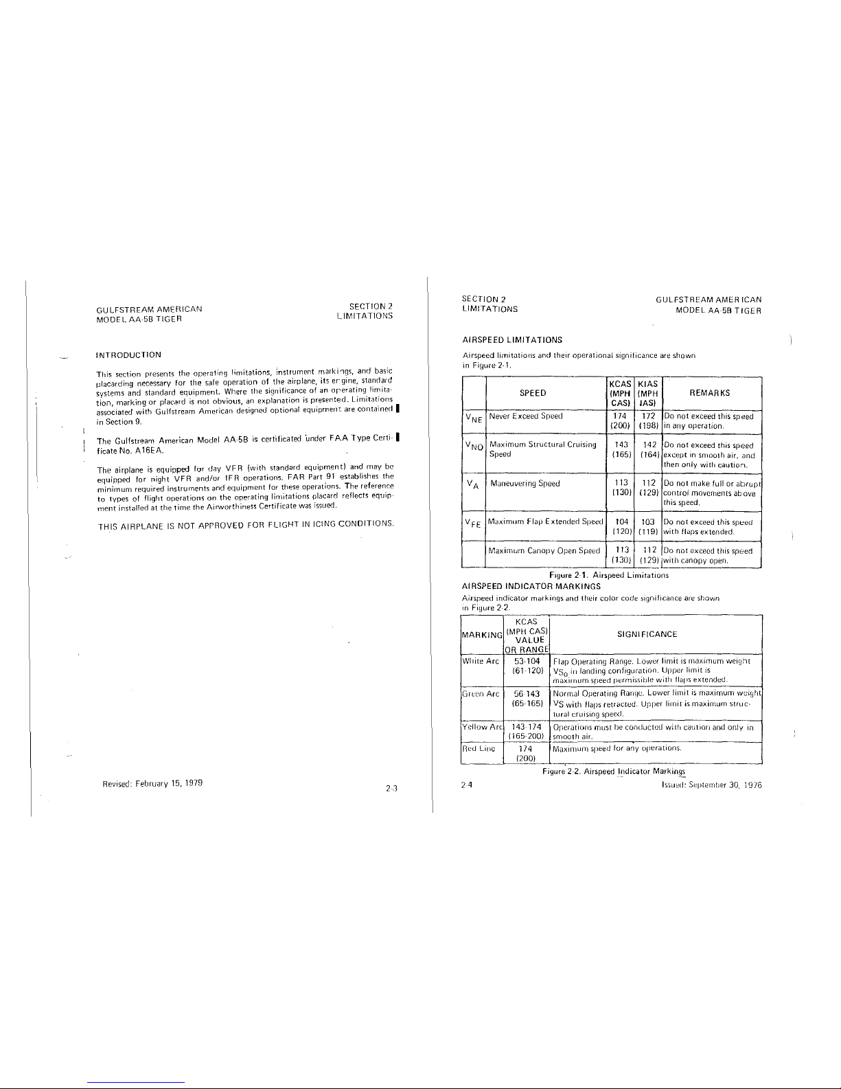
INTRODUCTION
SECTION 2
LIMITATIONS
This
section
presents
the
operating
limitations,
instrument
marki'1gs,
and
basic
placarding
necessary
for
the
safe
operation
of
the
airplane, its
ergine,
standard
systems
and
standard
equipment.
Where
the
significance
of
an
orerating
limita-
tion,
marking
or
placard
is
not
obvious,
an
explanation
is
presented.
Limitations
associated
with
Gulfstream
American
designed
optional
equipment
are
contained
I
in Section 9.
The
Gulfstream
American
Model
AA-58
is
certificated
'under
FAA
Type
Certi-
I
ficate No. A 16EA.
The
airplane
is
equipped
for
day
VFR
(with
standard
equipment)
and
may
be
equipped
for
night
VFR
and/or
IFR
operations.
FAR
Part
91
establishes
the
minimum
required
instrurnents
and
equipment
for
these
operations_
The
reference
to
types
of
flight
operations
on
the
operating
lin1itations
placarrl
reflects
equip-
inent
installed
at
the
time
the
Airvvorthiness
Certificate
was
issued.
THIS
AIRPLANE
IS
NOT
APPROVED
FOR
FLIGHT
IN ICING
CONDITIONS.
Revised:
February
15,
1979
23
SECTION 2
LIMITATIONS
GULFSTREAM
AMERICAN
MODEL
AA5B
TIGER
AIRSPEED
LIMITATIONS
Airspeed
limitations
and
their
operational
significance
are
shown
in
Figure
2-1.
KCAS
KIAS
SPEED (MPH
(MPH
REMARKS
CASI
IASI
VNE
Never
Exceed
Sreed
174 172
Do
not
exceed
this
speed
(2001 (1981
in
any
operation.
VNO
Maximum
Structural
Cruising
143 142
Do
not
exceed
this
speed
Speed
(1651 (1641
except
1n
smooth
air,
and
then
only
with
caution.
VA
Maneuvering
Sreed
113
112
Do
not
make
full
or
abrupt
(1301
1129)
control
movements
above
this
speed.
VFE
M<iximum
Flap
Extender!
Speed
104 103
Do
not
exceed
this
speed
I 120)
I
119)
with
flilps
extended.
Maximwn
Canopy
Open Speed
113
112
Do
not
exceed
tt1is speed
(130)
(129)
jwith
canopy
open.
Figure
2-1.
Airspeed
Limitations
AIRSPEED
INDICATOR
MARKINGS
Airspeed
indicator
markings
and
tt1eir
color
code
significance
are
shown
in
Figure
2·2.
KCAS
MARKING
(MPH CASI
SIGNIFICANCE
VALUE
OR RANGE
Wl1ite
Arc
53.104
Flap
Operating
Range.
Lower
limit
is
maximum
weigt1t
161·
120)
Vs
0
in
landing
configuration.
Upper
limit
is
maximum
speed
perrnissible
with
flaps
extendeci.
Grt:en
Arc
56-143
Normal
Operating
Ranqe.
Lower
limit
is
maximum
wei~Jhl
(65·
1651
Vs
with
flaps
retrac!ed.
Upper
limit
is
maximum
struc·
turnl
cruising
speed.
Yellow
Arc
143 174
Operations
must
be
conducted
with
caut'1on
and
only
'n
I 165·200)
smoo1~1
air.
Red
Linc
174
Maxirnurn
speed
for
any
operations.
(2001
Figure
2-2.
Airspeed
l~dicator
Markin~
24
lssu~d:
St~pternber
30,
1976
GULFSTREAM AEROSPACE
MODEL
AA-58 TIGER
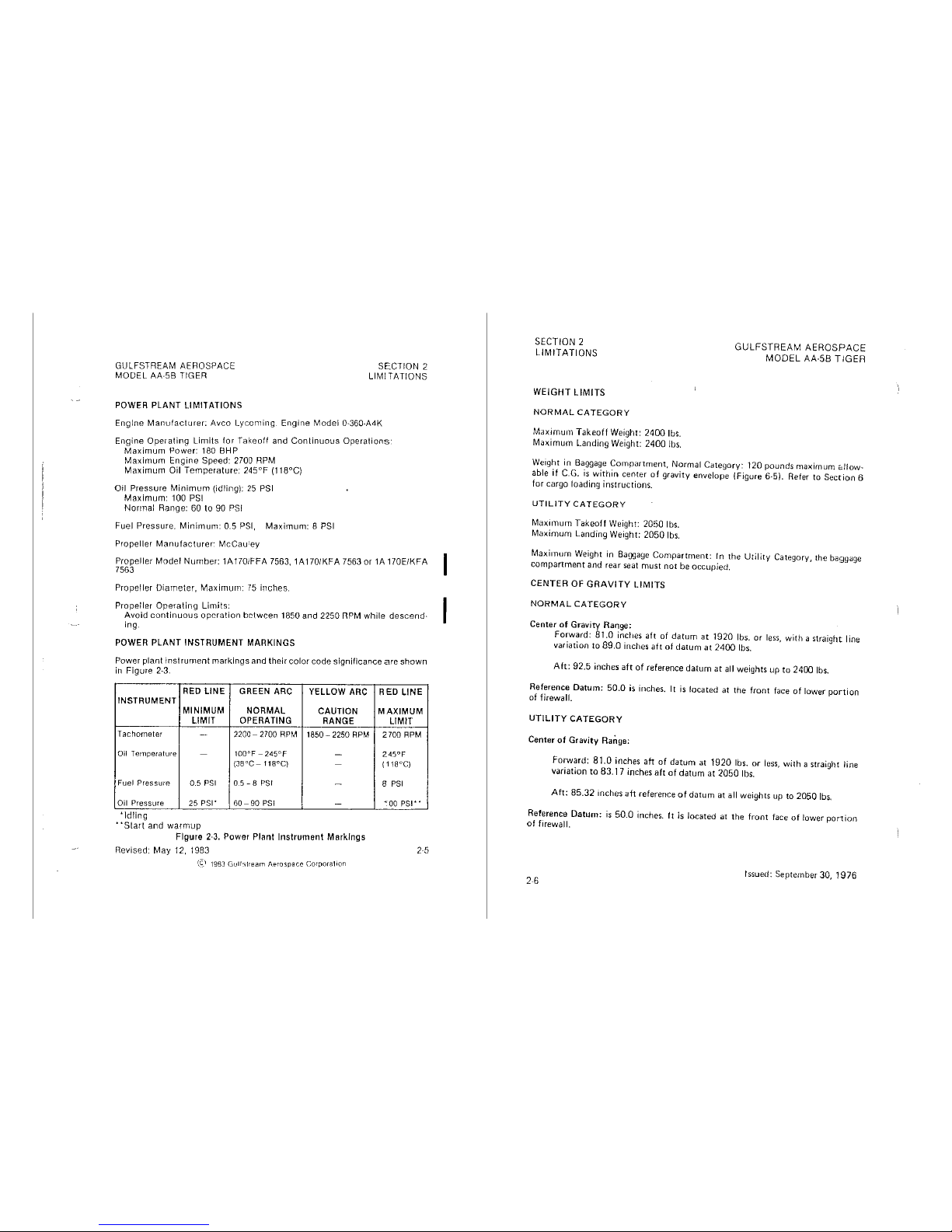
POWER PLANT LIMITATIONS
SECTION
2
LIMITATIONS
Engine
Manufacturer:
Avco Lycoming Engine Model 0-360-A4K
Engine
Operating
Limits
for Takeoff and
Continuous
Operations·
Maximum
Power:
180
BHP
Maximum
Engine Speed: 2700
RPM
Maximum
Oil Temperature: 245°F (118°C)
Oil Pressure
Minimum
(idling):
25
PSI
Maximum:
100
PSI
Normal
Range:
60
to
90
PS!
Fuel Pressure.
Minimum:
0.5
PSI,
Maximum: 8 PSI
Propeller
Manufacturer:
McCau1ey
Propeller
Model Number: 1A1701FFA 7563, 1A170/KFA 7563 or 1A 170E/KFA
7563
Propeller Diameter,
Maximum:
75
inches.
Propeller
Operating
Limits:
.
Avoid
continuous
opcrntion
between
1850
and
2250
nPM
while
descend·
ing.
POWER PLANT INSTRUMENT MARKINGS
Power plant
instrument
markings and their color code significance
are
shown
in Figure 2-3.
RED LINE GREEN ARC
YELLOW
ARC
INSTRUMENT
MINIMUM NORMAL
CAUTION
LIMIT OPERATING
RANGE
Tachometer -
2200-
2700
RPM
1850-
2250
RPM
Oil Temperature
-
100°F-245°F
-
{J8°C-
t 18°C)
-
Fuel Pressure 0.5
PSI
0.5-8
PS!
-
Oil Pressure
25
PSI•
60-90
PSI
-
'Idling
..
Start
and
warm
up
Figure
2-3.
Power Plant
Instrument
Markings
Revised: May 12, 1983
(C,\
1983
Gull:,1ream
Aerospace
Corporalion
RED
LINE
MAXIMUM
LIMIT
2700
RPM
245°F
{118°C)
B
PSI
~
00
PSI
..
SECTION 2
LIMITATIONS
WEIGHT
LIMITS
NORMAL
CATEGORY
Maximum
Takeoff
Weight: 2400 lbs.
Maximum
Landing Weight: 2400 lbs.
GULFSTREAM
AEROSPACE
MODEL
AA-58
TIGER
Weight in Baggage
Compartment,
Normal
Category:
120
pounds
maximum
c.llow-
able
if
C.G.
is
within
center
of
gravity
envelope
(Figure
6-5). Refer
to
Section
6
for
cargo
loading
instructions.
UTILITY
CATEGORY
Maximum
Takeoff
Weight: 2050 lbs.
Maximum
Landing Weight:
2050
lbs.
Maximum
Weight in Baggage
Compartment:
In
the
Utility
Category,
the
baggage
compartment
and
rear
seat
must
not
be
occupied.
CENTER OF
GRAVITY
LIMITS
NORMAL
CATEGORY
Center
of
Gravity
Range:
Forward:
81.0 inches
aft
of
datum
at
1920 lbs.
or
less,
with a straight
line
variation
to
89.0
inches
aft
of
datum
at
2400
lbs.
Aft:
92.5 inches
aft
of
reference
datum
at
all
weights
up
to
2400 lbs.
Reference
Datum:
50.0
is
inches.
It
is
located
at
the
front
face
of
lower
portion
of firewall.
UTILITY
CATEGORY
Center of Gravity
Rarige:
Forward:
81.0 inches ah
of
datum
at 1920 lbs.
or
less,
with
a straight line
variation
to
83.17 inches aft
of
datum
at
2050 lbs.
Ah:
85.32 inches
ah
reference
of
datum
at
all
weights
up
to
2050 lbs.
Reference
Datu1n:
is
50.0
inches. It
is
located
at
the
front
face
of
lower
ponion
of
firewall.
26
Issued:
September
30,
1976
GULFSTREAM
AMERICAN
MODEL
AA5B
TIGER
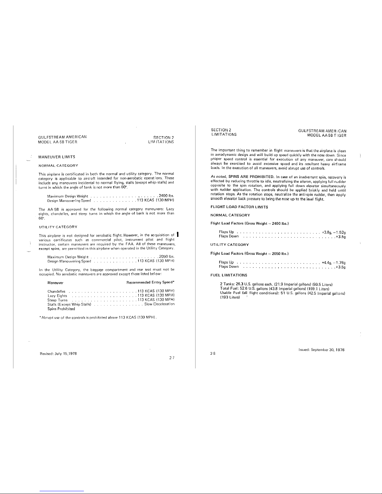
MANEUVER
LIMITS
NORMAL
CATEGORY
SECTION 2
LIMITATIONS
This
airplane
is
certificated
in
both
the
normal
and
utility
category.
The
normal
category
is
applicable
to
aircraft
intended
for
non-aerobatic
operat\ons.
These
include any maneuvers incidental
to
normal flying, stalls (except
whip
stalls) and
turns
in
which the angle of bank
is
not more than
600.
·
Maximum Design Weight
Design
Maneuverinq
Speed
........
2400 lbs.
. 113
KCAS 1130 MPH)
The
AA-5B
is
approved
for
the
following
normal
category
maneuvers:
Lazy
eights,
chandelles,
and
steep
turns
in
which
the
angle
of
bani<
is
not
more
than
60".
UTILITY
CATEGORY
This airplane
is
not
designed for aerobatic flight. However,
in
the acquisition
of
I
various certificates such
as
commercial pilot,
instrument
pilot
and
flight
instructor,
certain
maneuvers
are
required
by
the
FAA.
All
of
these
maneuvers,
except
spins,
are
permitted
in
this
airplane
when
011erated in
the
Utility
Category.
Maximum
Design
Weight
Design
Maneuvering
Speed
. 2050 lbs.
. 113
KCAS
1130
MPH)
In
the
Utility
Category,
the
baggage
compartment
and
rear
seat
must
not
be
occupied.
No
aerobatic
maneuvers
are
approved
except
those
listed
below:
Maneuver
Chandelles
Lazy
Eights
Steep
Turns
Stalls
(Except
Whip
Stalls)
Spins
Prohibited
Recommended
Entry
Speed*
.
113
KCAS 1130 MPH)
.
113
KCAS (130 MPH)
.
113
KCAS 1130 MPH)
Slow
Deceleration
..
Abrupt
use
of
the
controls
is
prohibited
above
113 KCAS {130 MPH}.
Revised:
July
15,1978
2 7
SECTION 2
LIMITATIONS
GULFSTREAM
AMER 1
CAN
MODEL AA-56
TIGER
The
important
thiny
to
remember
in flight
maneuvers
is
that
the
airplane
is
dean
in
aerodynamic
design
and
will
build
up
speed
quickly
with
the
nose
down.
Since
proper
speed
control
is
essential
for
execution
of
any
maneuver,
care
should
always
be
exercised
to
avoid
excessive
speed
and
its
resultant
heavy
airframe
loads. In
the
execution
of
all
maneuvers,
avoid
abrupt
use
of
controls.
As
noted,
SPINS
:4-RE
PROHIBITED.
In
case
of
an
inadvertent
spin,
recovery
is
effect~
by
reduc1n~
thrott!e
to
idle,
neutralizing
the
aileron,
applying
full
rudder
o~pos1te
to
the
.sp1~
rotation,
and
applying
full
down
elevator
simultaneously
with.
rudder
application.
The
controls
should
be
applied
briskly
and
held
until
rotation
stops.
As
the
rotation
stops,
neutralize
the
anti-spin
rudder,
then
apply
smooth elevator
back
pressure
to
bring
the
nose
up
to
the
level
flight.
FLIGHT
LOAD
FACTOR
LIMITS
NORMAL
CATEGORY
Flight
Load
Factors
(Gross
Weight
- 2400 lbs.)
Flaps Up
..
Flaps
Down
UTILITY
CATEGORY
Flight
Load
Factors
(Gross
Weight
- 2050 lbs.)
Flaps Up
..
Flaps
Down
FUEL
LIMITATIONS
+3.Bg,
-1.52g
.....
+3.5g
+4.4g,
-1.
76g
.....
+3.5g
2 Tanks: 26.3 U.S. gallons
each.
121.9 Imperial gallons) (99.5 Liters)
Total
Fuel: 52.6 U.S. gallons 143.8 Imperial gallons) (199.1 Liters)
28
Us.able
Fuel
(all
flight
conditions):
51
U.S.
gallons
(42.5 Imperial galiions)
(193 Liters)
Issued:
September
30,
1976
GULFSTREAM AMERICAN
MODEL
AA
5B
TIGER
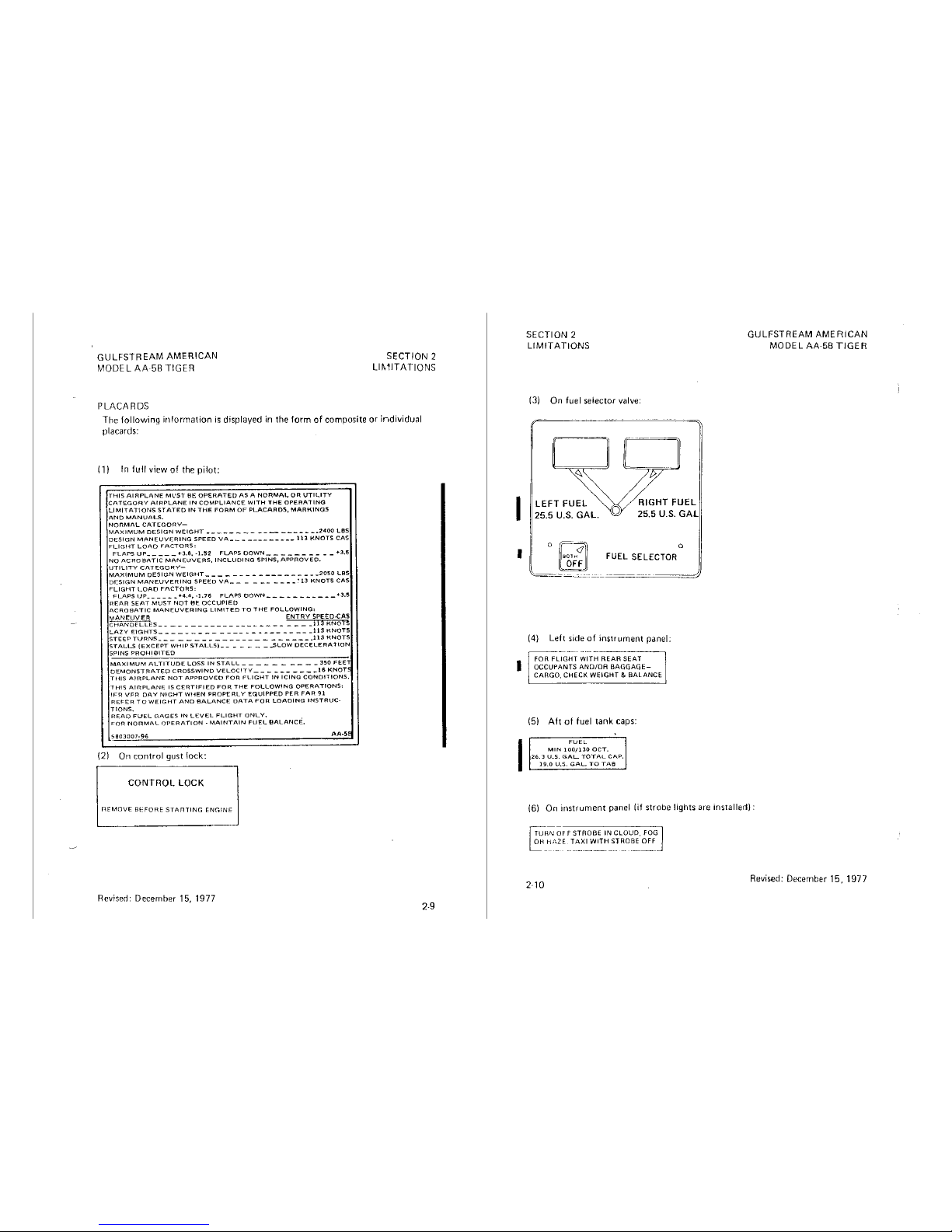
PLACARDS
SECTION
2
LIMITATIONS
The
following
information
is
displayed in the
form
of
composite or individual
placards:
( 1) In
full
view
of
the
pilot;
THIS
AIRPLANE
Ml'ST
BE
OPERATED
AS A NORMAL
OR
UTILITY
CATEGORY
AIRPLANE
IN
COMPLIANCE
WITH
THE
OPERATING
LIMITATIONS
STATED
IN
THE
FORM
OF
PLACARDS,
MARKINGS
AND
MANUALS.
NORMAL
CATEGORY-
MAXIMUM
DESIGN
WEIGHT ------ - ----
---
- -
__
2400
LBS
DESIGN
MANEUVERING
SPEED
VA-
- -
----
- - ---l
13
KNOTS
CAS
FLIGHT
LOAD
FACTORS:
FLAPS
UP
_____
+l.6,-1.52
F"LAPS
DOWN_
- - _ --____
+J.5
NO
ACROBATIC
MANEUVERS,
INCLUDING
SPINS,
APPROVED,
UTILITY
CATEGORY-
MAXIMUM
DESIGN
WEIGHT
- - - - - - - - -
----
- - - -
_2oso
LBS
DESIGN
MANEUVERING
SPEED
VA
___
_ --____
ClJ
KNOTS
CAS
FLIGHT
LOAD
FACTORS,
FLAPS
UP
______
+4.4,
-1.76
FLAPS
OOWN
- -
_________
+3.5
REAR
SEAT
MUST
NOT
0E
OCCUPIED
ACROBATIC
MANEUVERING
LIMITED
TO
THE
FOLLOWING1
MANEUVER
ENTRY
SPEED.CAS
CHANDfLLES
_______
-----
--------
____
ti3
KNOfS
LAZY
EIGHTS-----
- -
___
---
- -
------___
l13KNOTS
STEEP
TURNS
___ ----__
------
- -
______
113
KNOTS
STALLS
(EXCEPT
WHIP
STALLS)
_______
,.SLOW
DECELERATION
SPINS
PROHIBITED
MAXIMUM
ALTITUDE
LOSS
IN
STALL
___
- - _
____
350
FEE
DEMONSTRATED
CROSSWIND
VELOCITY
__ -_______
16
KNOr
THIS
AIRPLANE
NOT
APPROVED
FOR
FLIGHT
IN
ICING
CONDITIONS.
THIS
AIRPLANE
IS
CERTIFIED
FOR
THE
FOLLOW!l'<G
OPERATIONS1
IFR
VFR
DAY
N!GHT
WHEN
PROPERLY
EQUIPPED
PER
FAR
91
REFER
TO
WEIGHT
ANO
BALANCE
DATA
FOR
LOADING
INSTRUC-
TlONS.
READ
FUEL
GAGES
IN
LEVEL
FLIGHT
ONLY.
FOR
NORMAL
OPERATION -MAINTAIN
FUEL
0ALANCE',
5603007-96
AA-Sf
(2) On
control
gust lock:
CONTROL LOCK
REMOVE BEFORE
STARTING
ENGINE
Revised:
December
15,
1977
I
I
SECTION 2
LIMITATIONS
(3)
On
fuel
selector
valve:
LEFT FUEL
25.5
U.S.
GAL.
0
RIGHT FUEL
25.5
U.S.
GAL
Q
FUEL SELECTOR
(4) Left side
of
instrument
panel:
(5)
Aft
of
fuel
tank
caps:
I
FUEL
MIN
100/130
OCT.
26.3
U.S.
GAL
TOTAL
CAP.
19.0
U.S.
GAL
TO
TAB
GULFSTREAM AMERICAN
MODEL AA-5B
TIGER
(6)
On
instrument
panel
(if
strobe
lights are
installed):
~RNQFF
STROBE IN CLOUD.
FOG
~-Hi',ZE
TAXI WITH STROBE
OFF
-----
-·------~--···
-·
-~--
Revised: December
15,
197
7
GULFSTREAM AMERICAN
MODEL AA·5B TIGER
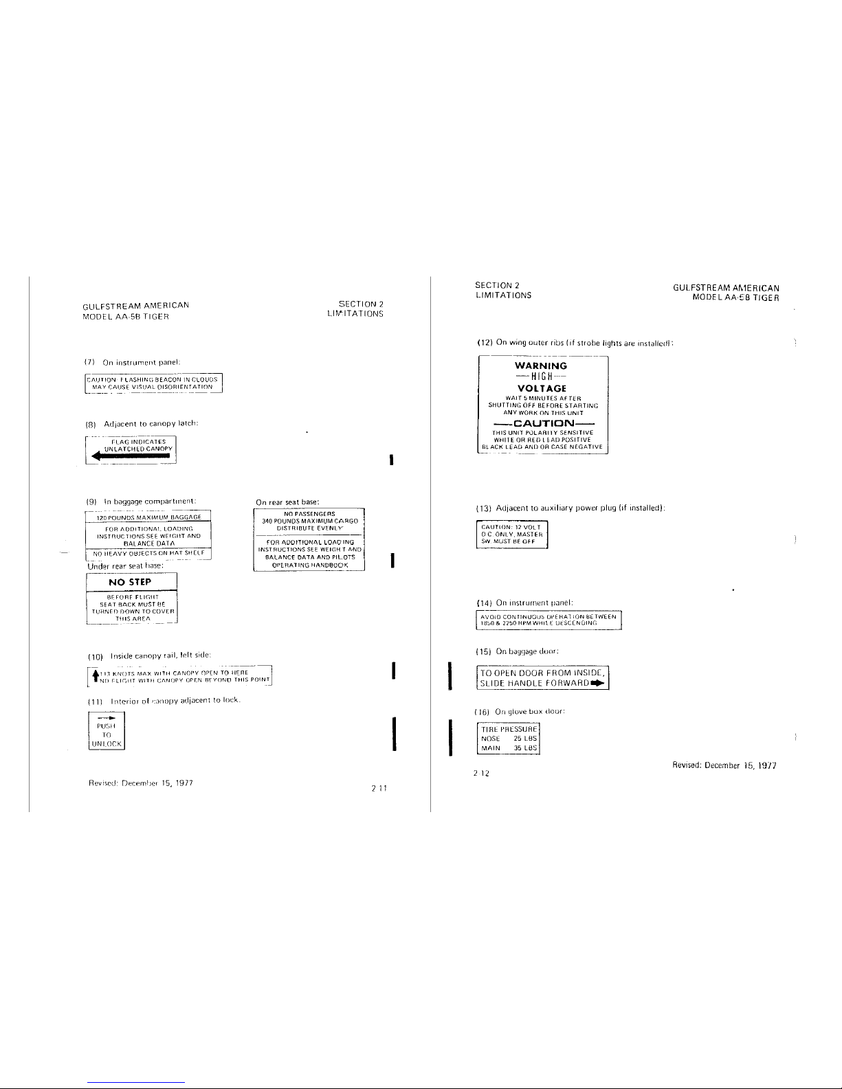
(7)
On
instrument
panel:
[
/\UT
ION F LASHINc;
BEA
co-~
IN
CLOUDS
MAY
CAUSE
VISUAL
DISORIENTATION
-
----
- ---
---------·---·-
---
(8)
Adjacent
to
canopy
latch:
(9) In baggage
compartment:
120
POUNDS
MAXIMUM
BAGGAGE
FOR
/\DDITIONAI_
LOADING
INSTnUCTIONS
SEE
WE!Gf!T
ANO
BALANCE DATA
NO
HEAVY
0!3JfCTS
ON
HAT
SHELF
Under
rear
seat
liase:
NO
STEP
BFFORF
FLIGHT
SEAT flACK MUST
flE
TURNED
f10WN
TO
COVER
THIS AREA
(10) Inside canopy
tail,
Ir.It side:
On
rear
seat
base:
SECTION 2
Lll\f
ITATIDNS
NO
PASSENGERS
340
POUNDS
MAXIMUM
CARGO
DISTRIBUTE
EVENLY
FOR
ADDITIONAL LOAOING
INSTRUCTIONS
SEE
WEIGHT
ANO
BALANCE
DATA
ANO
PILOTS
QPEAAllNG
HANDBOOK
111
KNOTS
MAX
WITH
CANOf'Y
OP[N
TO
HCRE
- .
..
. .
·----·:]
[ t
NO
rllrJllT
WITH
CANOPY
OPEN
Rf
YONO
THIS
POIN_T
{11)
l11terior
of
1:;i11opy
adjacent
to
lock.
-
PU'.;H
TO
UNLOCK
Revised: DP.CP.mlier
15,
1977
2
11
I
I
I
I
I
I
SECTION 2
LIMITATIONS
(12) On wing
outer
ribs
(1f
strobe lights
are
1nstallcdl:
WARNING
-HIGH--
VOLTAGE
WAIT
ti
MINUTES
AFTER
SHUTTING
OFF
BEFORE
STARTING
ANY
WORK
ON
THIS
UNIT
-CAUTION-
rH1s
UNIT
PULARI
l y
SENSITIVE
WHITE
OR
RED
l
~AD
POSITIVE
BLACK
LEAD
AND
OR
CASE
NEGATIVE
(13)
Adjacent
to
auxiliary
power plug
(if
installed):
CAUTION-
12
VOLT
DC
ONLY.MASTEH
SW
MUST
BE
OFF
{14)
On
instrument
panel:
AVOID
CONTINUOlJ~
Of'EHAl
ION
l:IETWEEN
18;,0
&
2250
HPM
WHll
(
Ut:SCCNUING
{ 15) On
bau~Jage
door.
TO
OPEN
DOOR FROM INSIDC,
SLIDE
HANDLE
fORWARD•
( J 6)
On
glove
liux
door:
TIRE
1-'RESSURf
NOSE 25 L8S
MAIN
35
LBS
2
12
GULFSTREAM
AMERICAN
MODEL
Ak5B
TIGER
Revised:
December
15,
1977
GULFSTREAM
AMERICAN
MODEL
Ak5B
TIGER
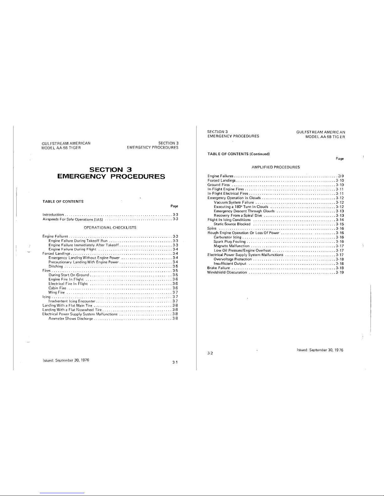
SECTION 3
EMERGENCY
PROCEDURES
SECTION 3
EMERGENCY
PROCEDURES
TABLE
OF
CONTENTS
Page
Introduction
........
. . .
..
. . . . . . . .
.. ..
. . .
..
. . . .
.....
33
Airspeeds
For
Safe
OpenHions
(IAS)
. . . . . . . . . . . . . . . . . . . . .
.........
3.3
OPERATIONAL
CHECKLISTS
Engine Failures . .
............................................
3-3
Engine Failure During Takeoff Run
...........................
3-3
Engine
Failure Immediately
After
Takeoff
........................
3-3
Engine
Failure
During
Flight
. ,
.................................
3-4
Forced Landings. . . . .
....................................
3-4
Emergency Landing
Without
Engine Power
............ , ...........
3-4
Precautionary
Landing
With Engine
Power
................
,
........
3-4
Ditching
. . . . . . . . . . . . .
..........................
3-5
Fires . . . . . . . . . . . . . . . . . . . . .
.................
,
...........
3-5
During
Start
On
Ground
. . . . .
........................
3-5
Engine Fire
In
Flight
. . . . . . . . . . . . . . . . . . .
...
3-6
Electrical Fire
In
Flight . . . .
.....................
3-6
Cabin Fire . . . . . . . . . . 3·6
Wing Fire
.........
.
Icing
......
.
Inadvertent
Icing
Encounter
........
.
Landing
With a Flat Main Tire
..
Landing With a
Flat
Nosewheel Tire
..........
.
Electrical
Power
Supply
System
Malfunctions
Ammeter
Shows
Discharge . .
......
.
:ssued: September 30, 1976
.
3-7
. . 3 7
.
..
3-7
. . 3·8
..
......
3-8
..
3-8
.......
38
3 1
SECTION
3
GULFSTREAM
AMERICAN
MODELAA5B
TIGER
EMERGENCY
PROCEDURES
TABLE
OF
CONTENTS
(Continued)
Page
AMPLIFIED
PROCEDURES
Engine Failures
.................................................
3-9
Forced
Landings . . . . . . . . . . . . . . . . . . . . . . . . . . . . . . . . . . . . . . .
...
3-10
Ground
Fires
.................................................
3-10
In-Flight Engine Fires
...........................................
3-11
In-Flight Electrical Fires
................................
,
........
3-11
Emergency
Operation
in
Clouds
...... , ...............
,
............
3-12
Vacuum
System
Failure
......................................
3·
12
Executing
a 1
BD°
Turn
in
Clouds
..................
,
............
3-12
Emergency
Descent
Through
Clouds
............................
3-13
Recovery
From a Spiral
Dive
..................................
3-13
Flight In Icing
Conditions
.......................................
3-14
Static
Source
Blocked
.......................................
3-15
Spins
.......................................................
3-16
Rough
Engine
Operation
Or
Loss
Of
Power
.........................
3-16
Carburetor
Icing..................................
.
....
3-16
Spark
Plug
Fouling
. . . . . .
..................................
3-16
Magneto
Malfunction
. . . . . . . . . . . . . . . . . .
.................
3-17
Low Oil
Pressure/Engine
Overheat
..............................
3-17
Electrical
Power
Supply
System
Malfunctions
...............
,
........
3-17
Overvoltage
Protection
................................
,
......
3-18
Insufficient
Output
.........................................
3-18
Brake
Failure
.................................................
3-18
Windshield
Obscuration
...... , ......................
,
........ , ..
3-19
3-2
Issued: September 30,
1976
GULFSTREAM
AMERICAN
MODEL
AA~5B
TIGER
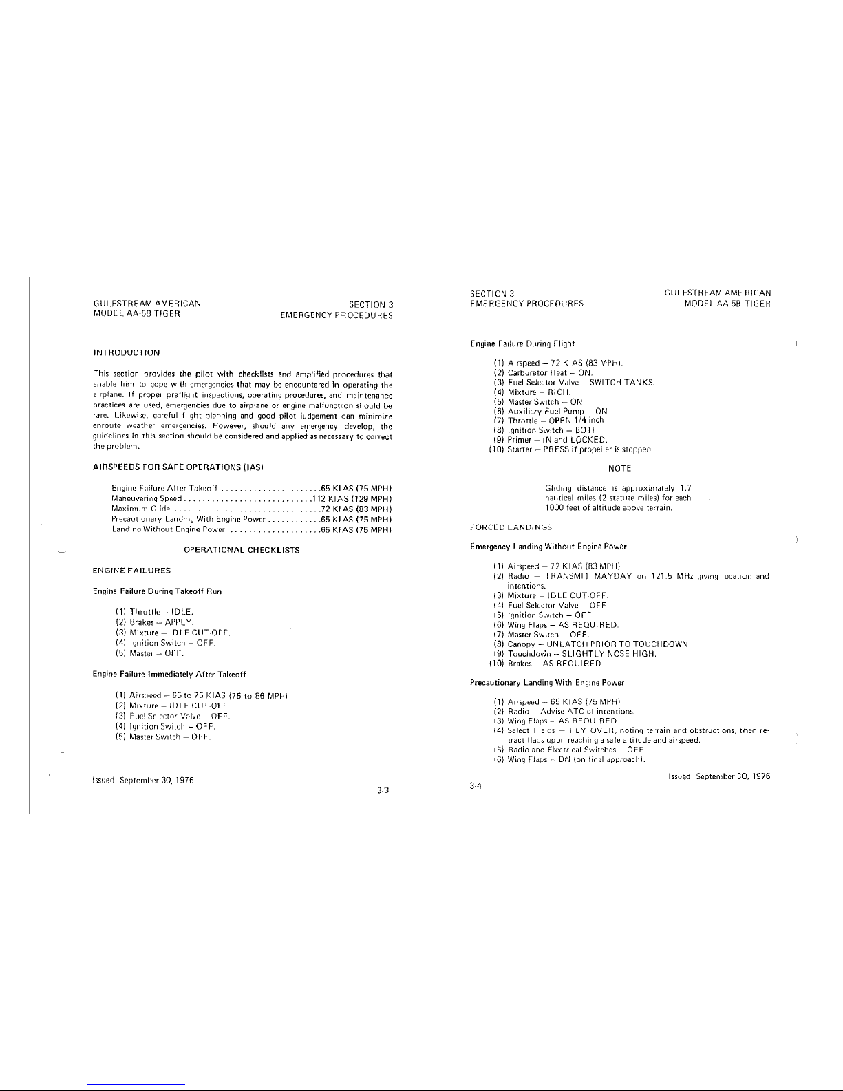
INTRODUCTION
SECTION 3
EMERGENCY PROCEDURES
This
section
provides
the
pilot
with
checklists
and
amplified
procedures
that
enable
him
to
cope
with
emergencies
that
may
be
encountered
in
operating
the
airplane. If
proper
preflight
inspections,
operating
procedures,
and
maintenance
practices
are
used,
emergencies
rlue
to
airplane
or
engine
malfunction
should
be
rare. Likewise,
careful
flight
planning
and
good
pilot
judgement
can
minimize
enroute
weather
emergencies.
However,
should
any
er;nergency
develop,
the
guidelines
in
this
section
should
be
considered
and
applied
as
necessary
to
correct
the
problen1.
AIRSPEEDS FOR SAFE
OPERATIONS
(IAS)
Engine Foi!ure
After
Takeoff
....... , .....
, . ,
... , ..
65 Kl AS (75 MPH)
Maneuvering
Speed
...................
,,
.....
, .112
KIAS
(129
MPH)
Maximum
Glide
.....................
72
KIAS
183
MPH)
Precautionary
Landing With Engine Power
..........
, .65
KIAS
(75
MPH)
Landing
Without
Engine Power
....................
65
KIAS
(75
MPH)
OPERATIONAL
CHECKLISTS
ENGINE
FAILURES
Engine Failure During Takeoff Run
Ill
Throttle -IDLE.
12)
Brakes - APPLY.
13)
Mixture -IDLE
CUT~OFF.
(4)
Ignition
Switch - OFF.
151
Master - OFF.
Engine Failure Immediately After Takeoff
11)
Aicspeed - 65
to
75 KIAS
175
to
86 MPH)
121
Mixture -IDLE
CUT~OFF.
{3) Fuel Selector Valve - OFF.
(4)
Ignition
Switch - OFF.
(5) Master Switch - OFF.
Issued: September 30, 1976
SECTION 3
GULFSTREAM
AME
RICAN
MODEL
AA·SB
TIGER
EMERGENCY
PROCEDURES
Engine Failure During Flight
Ill
Arr>peed - 72
KIAS
183
MPH).
(2)
Carburetor Heat - ON.
13)
Fuel Selector Valve
-SWITCH
TANKS.
141
Mixture
- RICH.
(5) Master Switch -
ON
(6)
Auxiliary Fuel Pump -
ON
(7)
Throttle
- OPEN
1/4
inch
(8)
Ignition Switch -
BOTH
191
Primer - IN and LOCKED.
(10) Starter - PRESS
if
propeller
is
stopped.
NOTE
Gliding distance
is
approximately 1.7
nautical miles {2 statute miles) for each
1000 feet of altitude above terrain.
FORCED
LANDINGS
Emergency
landing
Without Engine Power
Ill
Airspeed - 72
KIAS
183
MPH)
(2) Radio - TRANSMIT MAYDAY on 121.5 MHz giving location and
intentions.
131
Mixture -ID
LE
CUTOFF.
(4) Fuel Selector Valve - OFF.
(5) Ignition Switch - OFF
(6) Wing Flaps - AS REOUI RED.
(7) Master
Switch -
OFF.
(8) Canopy -
UNLATCH
PRIOR TO TOUCHDOWN
19)
Touchdown -
SLIGHTLY
NOSE
HIGH.
(10)
Brakes-
AS
REQUIRED
Precautionary
landing
With Engine Power
3-4
Ill
Air>peed - 65
KIAS
175
MPH)
(2) Radio - Advise
ATC
of intentions.
131
Wing
Flaps-
AS
REQUIRED
(4) Select Fields - FLY OVER, noting terrain and obstructions,
then
re-
tract flaps upon reactiing a safe altitude and airspeed.
(5)
Radio and Electrical Switches - OFF
(6)
Wing
Flaµs --·ON
{on
final
approach).
Issued: September
30,
1976
GULFSTREAM
AMERICAN
MODEL
AA-58
TIGER
SECTION
3
EMERGENCY
PROCEDURES
17)
Aicspeed - 65
KIAS
175
MPH)
(8) Master
Switch -OFF.
191
Canopy -
UNLATCH
PRIOR TO
TOUCHDOWN.
110)
Touchdown -SLIGHTLY
NOSE
HIGH.
(11)
Ignition
Switch
- OFF
(12) Brakes - AS
REQUIRED.
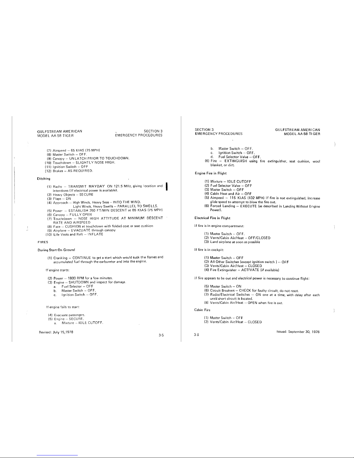
Ditching
111
Radio -
TRANSMIT
MAYDAY
ON 121.5 MHz, giving
location
and I
intentions
(lf
electrical power
is
available).
121
Heavy Objects - SECURE
131
Flaps -
ON
(4) Approach - High Winds, Heavy
Seas --INTO
THE WIND.
Light Winds, Heavy Swells -
PARALLEL
TO
SWELLS.
151
Power -
ESTABLISH
350
FT/MIN
DESCENT
at
65 KIA.S
175
MPH)
161
Canopy -
FULLY
OPEN
171
Touchdown
- NOSE
HIGH
ATTITUDE
AT
MINIMUM
DESCENT
RATE
AND
AIRSPEED
(8)
Face
- CUSHION at
touchdown
with
folded coat or
seat
cushion
(9) Airplane -
EVACUATE
through canopy
I 10) Life Vests and Raft -
INF
LATE
FIRES
During
Start
On
Ground
(
1)
Cranking -
CONTINUE
to
get a start which wou!d suck
the
flames and
accumulated
fuel
through
the
carburetor
and
into
the
engine.
If
engine starts:
(2) Power - 1800
RPM
for a few minutes.
(3) Engine -
SHUTDOWN and inspect
for
damage.
a.
Fuel Selector - OFF
b. Master
Switch -OFF.
c.
Ignition Switch - OFF.
!f
engine fails
to
start:
(4)
Evacuate passengers.
(5)
Engine -
SECURE.
a.
Mixture - IDLE
CUTOFF.
Revised:
July
15, 1978
3.5
SECTION
3
GULFSTREAM
AMERICAN
MODEL
AA-58
Tl
GER
EMERGENCY
PROCEDURES
b.
Master
Switch
- 0
FF.
c. Ignition
Switch -OFF.
d. Fuel
Selector
Valve -
OFF.
(6) Fire -
EXTINGUISH
using fire
extinguisher,
seat
cushion,
wool
blanket,
or
dirt.
Engine Fire in Flight
(1)
Mixture -IDLE
CUTOFF
(2) Fuel
Selector
Valve -
OFF
131
Master Switch -
OFF
(4)
Cabin
Heat
and
Air -OFF
(5) Airspeed -
115
KIAS
1132 MPH)
If
fire
is
not
extinguished, increase
glide
speed
to
attempt
to
blow
the
tire
out.
(6)
Forced
Landing -EXECUTE
{as
described
in Landing
Without
Engine
Power).
Electrical
Fire
in
Flight
If fire
is
in
engine
compartment:
(1) Master
Switch-
OFF.
121
Venrs/Cabin
Air/Heat -OFF/CLOSED
(3)
Land
airplane
as
soon
as possible
If
fire
is
in
cockpit:
( 1)
Master
Switch -OFF
(2) All
Other
Switches
(except
ignition
switch) -OFF
(3)
Vents/Cabin
Air/Heat -CLOSED
(4) Fire Extinguisher -
ACTIVATE
(if
available!
If
fire
appears
to
be
out
and
electrical
power
is
necessary
to
continue
flight:
(
5)
Master
Switch
- ON
(6)
Circuit
Breakers - CHECK
for
faulty
circuit,
do
not
reset.
(7)
Radio/Electrical
Switches
- ON
one
at
a
time,
with
delay
after
each
until
short
circuit
is
located.
(8)
Vents/Cabin
Air/Heat
- OPEN
when
fire
is
out.
Cabin Fire
(1) Master
Switch -OFF
(2)
Vents/Cabin
Air/Heat
- CLOSED
3-0
Issued:
September
30,
1976
GULFSTREAM AMERICAN
MODEL AA·5B TIGER
SECTION
3
EMERGENCY PROCEDURES
{3)
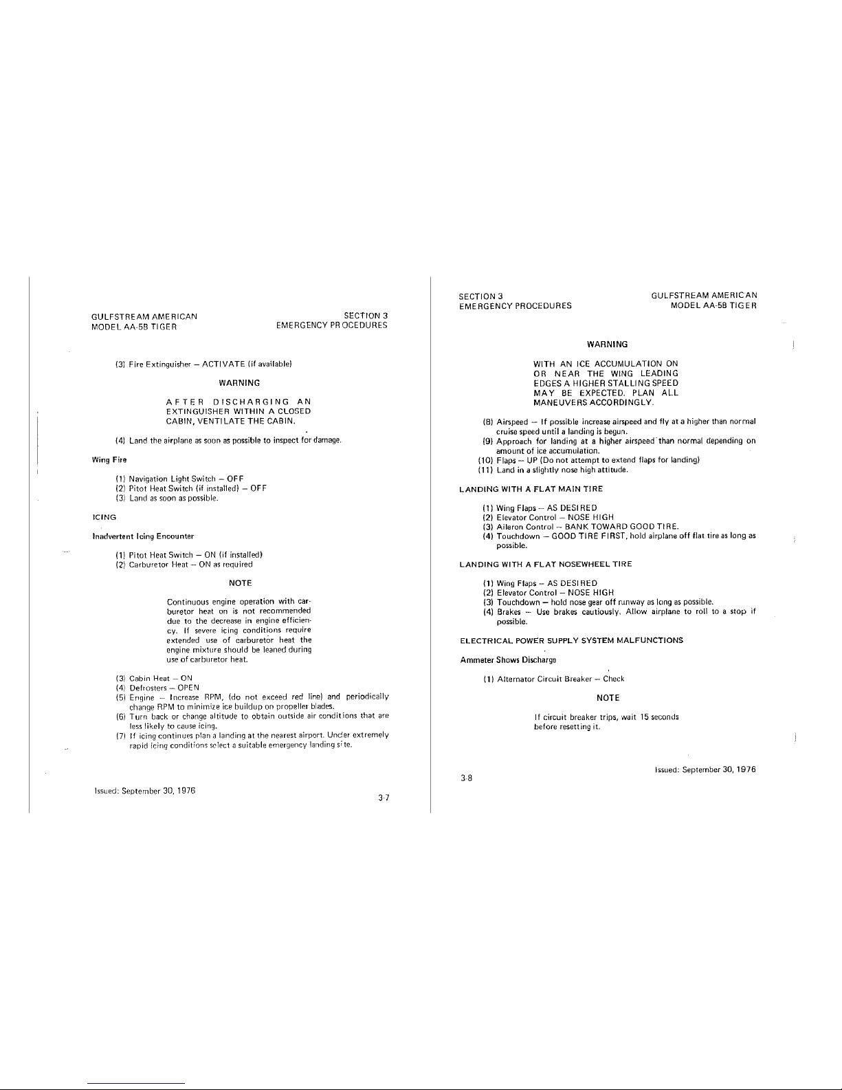
Fire Extinguisher - ACTIVATE
(if
available)
WARNING
AFTER
DISCHARGING
AN
EXTINGUISHER WITHIN A CLOSED
CABIN, VENT!
LATE THE CABIN.
(4) Land
the
airplane
as
soon as possible
to
inspect for damage.
Wing
Fire
ICING
(1)
Navigation Light Switch - OFF
(2) Pitot
Heat
Switch
(if
installed) - OFF
(3) Land
as
soon
as
possible.
Inadvertent
Icing
Encounter
(1)
Pitot
Heat
Switch -ON
(if
installed)
(2)
Carburetor Heat -
ON
as
required
NOTE
Continuous
engine
operation
with
car-
buretor
heat on
is
not
recommended
due
to
the
decrease
in
engine efficien-
cy.
If
severe icing
conditions
require
extended
use
of
carburetOr
heat
the
engine
mixture
should
be
leaned during
use
of
carburetor
heat.
(3)
Cabin
Heat - ON
(4) Defrosters - OPEN
(5)
Engine - Increase
RPM,
(do
not
exceed red
line)
and periodically
change
RPM
to
minimize ice
buildup
on
propelle1 blades.
(6)
Turn
back
or
change
altitude
to
obtain
outside
air
conditions
that
are
less likely
to
cause icing.
(7)
If icing
continues
p!an a
landing
at
the
nearest
airport.
Under
extremely
rapid icing
conditions
select a
suitable
ernergency landing
s;te.
Issued:
September
30,
1976
SECTION 3
GULFSTREAM
AMERICAN
MODEL AA·5B
TIGER
EMERGENCY PROCEDURES
WARNING
WITH AN
ICE
ACCUMULATION
ON
OR
NEAR
THE
WING
LEADING
EDGES
A HIGHER STALLING
SPEED
MAY
BE
EXPECTED. PLAN
ALL
MANEUVERS ACCORDINGLY.
(Bl
Airspeed - If possible increase airspeed
and
fly
at a higher
than
normal
cruise
speed
until a landing
is
begun.
(9)
Approach
for
landing
at a higher
airspeed·
than
normal
depending
on
amount
of
ice
accumulation.
(10) Flaps -
UP
(Do
not
attempt
to
extend
flaps for landing)
(11)
Land
in a slightly
nose
high
attitude.
LANDING
WITH A
FLAT
MAIN
TIRE
( 1)
Wing
Flaps -AS
DESI
RED
(2) Elevator Control -
NOSE
HIGH
(3) Aileron Control - BANK TOWARD GOOD
Tl
RE.
(4)
Touchdown
- GOOD
TIRE
FIRST,
hold
airplane
off
flat tire as
long
as
possible.
LANDING
WITH A
FLAT
NOSEWHEEL TIRE
(1)
Wing
Flaps -AS
DESIRED
(2) Elevator Control -
NOSE
HIGH
(3)
Touchdown
- hold
nose
gear
off
runway
as long as possible.
(4) Brakes - Use
brakes
cautiously.
Allow
airplane
to
roll to a
stop
if
possible.
ELECTRICAL
POWER
SUPPLY SYSTEM MALFUNCTIONS
Ammeter
Shows
Discharge
38
( 1)
Alternator
Circuit
Breaker
- Check
NOTE
If
circuit
breaker
trips,
wait
15
seconds
before
resetting
it.
Issued:
September
30,
1976
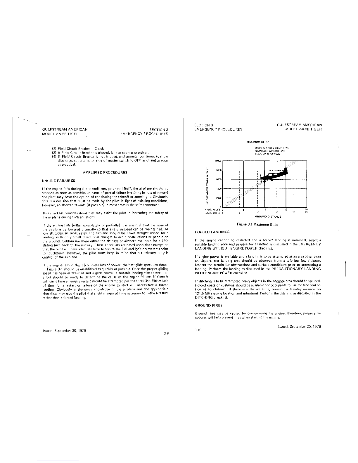
GULFSTREAM
AMERICAN
MOOEL
AA~5B
TIGER
(2) Field
Circuit
Breaker - Check
SECTION 3
EMERGENCY PROCEDURES
(3)
If
Field
Circuit
Breaker
is
tripped,
land
as
soon
as
practical.
(4) If
Field
Circuit
Breaker
is
not
tripped,
and
ammeter
continues
to
show
discharge,
set
alternator
side
of
master
switch
to
OFF
ard
land
as
soon
as practical.
AMPLIFIED
PROCEDURES
ENGINE
FAILURES
If
the engine fails during the takeoff run,
prior
to
liftoff,
the airpilane should
be
stopped
as
soon
as possible. In cases
of
partial failure (resulting in loss
of
power)
the
pilot
may
have
the
option
of
continuing
the
takeoff
or
aborting
it.
Obviously
this
is a decision
that
must
be
made
by
the
pilot
in light
of
existi:ng
conditions,
however,
an
aborted
takeoff
{if
possible)
in
most
cases
is
the
safest
approach.
This
checklist
provides
items
that
may
assist
the
pilot
in
increasin~
the
safety
of
the
airplane
during
such
situations.
If
the
engine
fails
(either
completely
or
partially)
it
is
essential
that
the
nose
of
the
airplane
be
lowered
promptly
so
that
a safe airspeed can be
maintained.
At
low
altitudes,
in
most
cases,
the
aiq1!ane
should
be
flown
straight
ahead
for a
landing,
with
only
small
directional
changes
to
avoid
obstructions
or
people
on
the
ground.
Seldom
are
there
either
the
altitude
or
airspeed
available
for
a 180"
gliding
turn
back
to
the
runway.
These
checklists
are based
upon
the
assumption
that
the
pilot
will have
adequate
time
to
secure
the
fuel
and
ignition
systems
prior
to
touchdown,
however,
the
pilot
must
keep
in
mind
that
his
primary
duty
is
control
of
the
airplane.
If
the
engine
fails in flight
(complete
loss
of
power)
the
best glide
speed,
as shown
in
Figure
3-1
should
be
established
as
quickly
as possible. Once
the
proper
gliding
speed
has
been
established
and
a glide
toward a suitable
landing
site
entered,
an
effort
should
be
made
to
determine
the
cause
of
the
engine fai! ure.
If
there
is
sufficient
time
an engine
restart
should
be
attempted
per
the
check[ist.
Either
lack
of
time
for a
restart
or
failure
of
the
engine
to
start
will
necessitate
a forced
landing.
Obviously a thorough
knowledge
of
the
airplane
and
the
appropriate
checklists
may
give
the
pilot
that
slight margin
of
time
necessary
to
make
a restart
rather
than a forced
!anding.
Issued:
September
30,
1976
39
SECTION 3
EMERGENCY PROCEDURES
MAXIMUM
GLIDF
GULFSTREAM
AMERICAN
MODEL AA-58
TIGER
SPEED
J2
KNOfS
!83 MPHI !AS
PROPELLER
WINOMILUNG
FLAPS
UP
ZERO WINO
OL..~~~-'--'-~~---'--~-'-~~'-~-'-~~~~
NAUT. MILES 0
STAT. MILES 0
FORCED
LANDINGS
10
10
GROUND
DIST
ANGE
Figure
3.1
Maximum
Glide
16
10
20
lJ
If
the
engine
cannot
be
restarted
and a forced
landing
is
imminent,
select
a
suitable
landing
zone
and
prepare
for a landing
as
discussed in
the
EMERGENCY
LANDING
WITHOUT
ENGINE
POWER
checklist.
If
engine
power
is
available
and
a landing
is
to
be
attempted
at
an area
other
than
an
airport,
the
landing area
should
be
obseived
from
a safe
but
!ow
altitude.
Inspect
the
terrain
for
obstructions
and
surface
conditions
prior
to
attempting
a
landing.
Perform
the
landing
as discussed in
the
PRECAUTIONARY
LANDING
WITH
ENGINE
POWER
checklist.
1f
ditching
is
to
be
atte~pted
heavy
objects
in
the
baggage area
should
be
secured.
Folded
coats
or
cushions
should
be available for
occupants
to
use for face
protec-
tion
at
touchdown.
If
there
i5
5ufficienl
ti111e,
transmit
a Mayday message
on
121.5
MHz giving
location
and
intentions.
Perform
the
ditching
as
discussed in
the
DITCHING
checklist.
GROUND
FIRES
Ground
fires
may
be
caused
by
over-priming
the
engine,
therefore,
proper
pro-
cedures
will help
prevent
fires
when
starting
the
engine.
Issued:
September
30,
1976
3
10
SECTION:
GULFSTREAM
AMERICAN
MOOELAA5BTIGER
EMERGENCY
PROCEDURE~
Should a ground
fire occur, the
following
procedures
are
suggested:
(
1)
Keep the engine running
to
ingest the flames into
carbur~tor.
Increase
engine
RPM
to
1800 RPM.
(2) Dispatch ground personnel
for
fire
equipment.
(3)
When
assistance
arrives,
turn
fue!
selector
valve
OFF.
Let
engine
stop
due
to
fuel starvation. Set Master
Switch
and lqnition Sv,ritch
to
OFF.
(4)
If
no
assistance
is
available
or
the fire
is
beyond
control,
turn
the fuel
selector
OFF,
mixture
OFF,
Mastet Switch OFF,
lgnitior"I
Switch OFF.
ABANDON
AIRCRAFT.
IN·FLIGHT
ENGINE
FIRES
In-flight
engine fires in today's modern
aircraft
are extremely rare.
It
should be
noted
that
the
presence
of
smoke
does
not
always
mean
that a flaming
fire exists.
For
example,
it
may
be
engine
oil
on
the
exhaust
system. If, in
the
pilot's
judgement,
an
engine
fire exists,
the
following
procedures
are
suggested:
111
Mixture -
IDLE
CUTOFF
(2)
Fuel
Selector
Valve -
OFF
(3) Master
Switch -OFF
(4)
Cabin
Heat
and
Air -OFF
(5)
Establish a maximum
safe
rate
of
descent.
Increasing
speed
may
blow
the
fire
out.
(6)
Slide
slip
maneuvers
may
be
used,
as
necessary,
to
direct
flames
away
from
cabin
area.
(7)
Select a suitable
field
for a forced
landing.
IBI
Notify
ATC
if possible.
(9)
Complete
the
forced
!anding. Do
not
attempt
to
restart
the
engine.
IN-FLIGHT
ELECTRICAL
FIRES
Indication
of
in·flight
electrical fires
may
be
wisps
of
smoke
or
the
smell
of
hot
or
burning
insulation.
Should
an
electrical
fire
develop,
the
fol(owing
procedures
are
suggested:
If
fire
is
in
engine
compartment:
(1) Master
Switch -OFF.
121
Vent/Cabin Air/Heat - OFF/CLOSED
(3)
Land
airplane
as
soon
as
possible
Revised:
July
15, 1978
3·
11
SECTION 3
GULFSTREAM
AMERICAN
MODEL
AA·5B
TIGER
EMERGENCY PROCEDURES
If
fire
is
in
cockpit:
(1) Master Switch - OFF
(2) All
Other
Switches
(except
ignition
switch) -OFF
(3) Vents/Cabin
Air/Heat
- CLOSED
(4) Fire Extinguisher -
ACTIVATE
(if
available)
If
fire
appears
to
be
out
and
electrical
power
is
necessary
to
continue
flight:
{!J)
Master
Switch
- ON
(6)
Circuit
Breakers -CHECK
for
faulty
circuit,
do
not
reset.
(7)
Radio/Electrical
Switches
- ON
one
at a time,
with
delay
after
each
until
short
circuit
is
located.
(8)
Vents/Cabin
Air/Heat -OPEN
when
fire is
out.
EMERGENCY
OPERATION
IN
CLOUDS
Vacuum
System
Failure
A
vacuum
system
failure
may
disable
the
directional
and
attitude
indicators,
thus
forcing
the
pilot
to
rely
on
the
turn
coordinator
or
turn
and
bank
indicator
if
he
inadvertently
flies
into
clouds.
The
following
procedures
assume
that
only
the
electrically"powered
turn
coordinator
or
turn
and
bank
indicator
is
operative,
and
the
pilot
is
not
instrument
rated.
Executing a 180"
Turn
in
Clouds
Upon
inadvertently
entering
the
clouds,
an
immediate
plan
should
be
made
to
turn
back
as follows:
3·
12
( 1)
Note
the
time
of
the
minute
hand
and
observe
the
position
of
the
sweep
second
hand
on
the
clock.
Note
compass
heading.
{2) When
the
sweep
second
hand
indicates
the
nearest
half-minute, initiat.e
a
standard
rate
left
turn,
holding
the
turn
coordinator
symbolic
airplane
wing
opposite
the
lower
left
index
mark
for
60
seconds.
Then roll
back
to
level
flight
by
leveling
the
miniature
airplane.
(3)
Check
accuracy
of
the
turn
by
observing
the
compass
heading
which
:;houlU
Le
reciprocal
of
the
original
heading.
(4) If
necessary,
adjust
heading
primarily
with
skidding
motions
rather
than
rolling
motions
so
that
the
compass
will
read
more
accurately.
(5)
Maintain
altitude
and
airspeed
by
cautious
application
of
elevator
con-
trol.
Avoid
overcontrolling
by
using a
very
small
pitch
control
changes.
Issued: September 30, 1976
GULFSTREAM
AMERICAN
MODEL
AA~5B
TIGER
SECTION
3
EMERGENCY PROCEDURES
Emergency
Descent
Through
Clouds
If
VFR
flight
conditions
cannot
be
re-established by performing a
180°
turn,
a
descent
through
the
cloud
deck
to VFR
conditions
may be
appropriate.
If
possible,
obtnin
radio clearance for an
emergency
descent
through
clouds.
To
guard
against a spiral dive,
choose
an easterly
or
Westerly heading
to
minimize
compass
card
swings
due
to
changing
bank
angles.
In
addition,
use a
minimum
control
wheel
movement
and steer a
straight
course
with
rudder
control
by
monitoring
the
turn
coordinator.
Occasionally
check
the
compass
heading
and
make
minor
corrections
to
hold an
approximate
course. Before
descent
into
the
I
clouds,
set
ur
a stabilized let-down
condition
as follows:
(
1)
Apply
full
carburetor
heat.
(2)
Reduce
power
to
set up a
500
to
600
ft./min.
rate of
descent.
(3)
Adjust
the
elevator
trim
control
wheel for a stabilized
descent
at
75
KIAS
186
MPH).
(4) Use
minimum
control
wheel
motion
and avoid
abrupt
movement.
(5)
Monitor
turn
coordinator
and
make
corrections
by
rudder
alone.
(6)
Check
trend
of
compass
card
movement
and make
cautious
corrections
with
rudder
to
stop
turn.
(7)
Upon
breaking
out
of
clouds,
resume
normal
cruising flight.
·Recovery Fro1n
a Spiral Dive
If a spiral
is
encountered,
proceed
as follows:
(1) Close throttle.
(2)
Stop
the
turn
by using
coordinated
aileron and rudder
control
to
align
the
symbolic
airplane
in
the
turn
coordinator
with
the
horizon
reference line.
(3)
Cautiously
apply
elevator
back
pressure
to
slowly reduce
the
indicated
airsreed
to
75 KIAS (86 MPH).
(4)
Adjust
the
elevator
trim
control
to
maintain a 75
KIAS (86 MPH) glide.
(5) Use
minimum
control
wheel
movement,
using
rudder
control
to
hold
a
straight
heading.
(6)
Apply
carburetor
heat.
(7) Clear engine occasionally,
but
avoid using enough power
to
disturb
the
trimmed
glide.
(BJ
Upon
breaking
out
of
clouds, resume normal cruising flight.
Revised: July 15,1978
3-13
SECTION 3
GULFSTREAM
AMERICAN
MODEL AA·5B
TIGER
EMERGENCY PROCEDURES
FLIGHT
IN
ICING
CONDITIONS
Carburetor
~ce
~ay
be
encountered
at
any time. Normally,
the
first indicatio;i
of
carburetor
ice
Jn
the
AA-58
is
a slight
drop
in
engine RPM which
be
. d b
1·
. '
may
accompan1e Y s 1ght engine roughness. If
carburetor
icing
is
suspected,
the
following
procedures
are suggested:
( 1)
Appl~
full
~arburetor
heat. Engine
roughness
may
then
occur
due
to
an
over-nch
mixture
or
water
from
the
melting
ice.
NOTE
Continuous
engine
operation
with
carburetor
heat
on
is
not
recommended
du~
~o
the
resultant
decrease
in
engine
etf1c1ency. If severe icing
conditions
re-
quire
extended
use
of
carburetor
heat
the
engine
mixture
should
be
leaned
during
use
of
carburetor
heat.
Flying
i~
k~o.wn
icing
conditions
is
prohibited
by FAA regulations. However,
should
wmg
1c1ng
occur
the
following
procedures
are suggested:
3-14
( 1)
Turn
pltot
heat
ON
(2)
Turn
cabin
heat
ON.
(3)
Open
windshield
defroster
vent.
(4)
If
IFR
o~
~nder
control
of
an
in-flight
ground
facility,
notify
them
of
the
cond.1t1on
and
request
assistance. A
change
of
altitude,
if
possible,
o~
reversin~
cou.rs:
to
fly
out
of
the icing
conditions
may be desirable.
(5)
Pilot
technique
1s
important
in this
situation:
A. Increase
and
decrease
engine
RPM
(do
not
exceed
red line)
to
keep
propeller
clear
of
ice.
B.
Increase ai.rspeed if possible. This
technique
reduces angle of at-
tack
exposing
less
surface
area for ice
accumulation.
C.
Do.
not
exte~d
flaps. A clean
configuration
will
expose
less
surface
_to
ice
a~d
will
prevent
a change in air flow over
the
tail surfaces.
(6)
Monitor
engine
RPM
for
any
indication
of
carburetor
ice.
(Refer
to
Carburetor
Ice Procedures.)
(7) Plan a landing
at
the
first suitable
airport.
The
following procedures are
suggested:
A.
~f
the
wi~?s~~eld
ls
obstructed,
the
canopy
may be opened
to
Improve v1s1b1hty. A forward slip may be helpful.
Issued:
September
30, 1976
GULFSTREAM
AMERICAN
MODEL
AA
58
TIGEn
SECTION
3
EMERGENCY
PR
OCEOURES
B.
Rernernber
that
ice
accumulntion
increases wing
loading,
decreases
performance,
decreases
range
and
INCREASES
STA
LL
SPEEDS.
When
landing,
plan a slightly
higher
than
normal
air
speed
during
landing
approach.
Guard
against increased stall
speed
created
by
the
above
mentioned
conditions.
Touch
down
in a slightly
nose
high
attitude.
REMEMBER:
Intentional
flying in icing conditions !S PROH!
SITED!
STATIC
SOURCE
BLOCKED
If
erroneous
readings
are
suspected
on
the
instruments
associated
with
the
pitot·static
system
{airspeed
indicator,
altimeter
and
vertical
speed
indicator)
pitot
heat
should
be
applied
(for
erroneous
airspeed
indications)
in
case
the
problem is due
to
ice
or
water
accumulation
in
the
pitot
head.
Fa~lure
of
pitot
heat
to
correct
the
problem
may
indicate
blockage
of
the
static
sources.
Obviously
in a
situation
such
as this, a
landing
should
be
planned
at
the
nearest
suitable
airport.
If
it
is
necessary
to
continue
the
flight,
and
particularly
if
the
flight
is
in
marginal
conditions, a static
source
must
be
supplied
to
the
airspeed
indicator
and
altimeter.
If
an
alternate
air
source
is
installed
on
your
airplane, a static
air
source
can
be
applied
to
these
instruments
by
pulling
out
the
ALT,STATlC
AIR valve
located
on
the
left
side
of
the
instrurnent
panel.
NOTE
Close
the
canopy
when
using
alternate
static
air
source.
At
airspeeds
above
87
KIAS 1100 MPH)
subtract
6 KIAS
17
MPH)
from
indicated
airspeed
and
80
feet
from
indicated
altitude.
If
your
airplane
is
not
equipped
with
an
alternate
static
air
source, a static
source
can
be
supplied
to
the
airspeed
indicator
and
altimeter
by
breaking
the
glass
on
the
face
of
the
vertical
speed
indicator.
If
this
is
done
remember
the
following:
( 1)
The
vertical
speed
indicator
will
be
inoperative.
(2)
Some
error
may
be
expected
in
airspeed
and
altitude
indications.
At
a;rspeeds
above
87 KIAS 1100 MPH)
subtract
6 KIAS
(7
MPH)
from
indicated
airspeed
and
80
feet
from
indicated
altitude.
(3)
The
canopy
must
be
kept
closed,
since
opening
it
could
introduce
large
errors
in
airspeed
and
altitude
indications.
Issued:
September
30,
1976
3-15
SECTION
3
GULFSTREAM
AMER!
CAN
MODEL
AA-58
Tl
GER
EMERGENCY
PROCEDURES
SPINS
-;~e
A:-58
is1nNoTt
certificated
for
spins,
in
either
the
Normal
or
Utility
category
ere
ore,
ENTIONAL
SPINS
ARE
PROHIBITED
H ,
1'
i d t · . owever,
snoud
na
ver
ent
spm
occur,
the
following
recovery
procedure
is
recomrnended:
(1)
Throttle -Idle
(2)
Ailerons -Neutral
{3)
Rudder -Hold
opposite
direction
of
rotation,
full
rudder,
:~t
Elevator
-
Ful.I
forward,
s!n:iultaneously
with
rudder
application.
Hold
contr?ls
In
these
pos1t1ons
until
rotation
stops.
{6}
When
rotation
stops
neutralize
rudder
and
recover
fronl
dive.
NOTE
If
disorientation
precludes
a visual
determination
of
the
direction
of
rotation,
the
symbolic
airplane
in
the
turn
coordinator
or
the
needle
of
the
turn
and
bank
indicator
may
be
referred
to
for
this
information.
ROUGH
ENGINE
OPERATION
OR
LOSS
OF
POWER
Carburetor
Icing
An
I.
d ·
un.exp
ame
drop
J~
RPM
and
engine
roughness
may
result
from
the
:~~ml~~';)n
aofd
carb~re~or
ice.
To
clear
the
ice,
apply
full
throttle
(do
not
exceed
n pu t e
carburetor
heat
knob
full
out
until
the
engine
runs
~mo~thly.
Then
_remove
carburetor
heat
and
readjust
the
throttle.
Jf
conditions
equ1re
the
contmued
use
of
carburetor
heat
in
cruise
flight
use
the
minim
amounht
of
_heat
nece~ry
to
prevent
ice
from
forming
and
lean
the
mixture
~;;:
smoot
engine
operation.
Spark
Plug
Fouling
A
slig~t
engine
roughness
in
flight
may
be
caused
by
one
or
mores
ark
Ju s
?ec.o.mtng
f?uled
by
carbon
or
lead
deposits.
This
may
be
verified
by
t~rnin~
t~e
ignition
swu_ch
~ome~ta.ri.ly
from
BOTH
to
either L or R position.
An
obvious
iow~~
lo;s
in
~mg!e
1gnn1on
operation
is
evidence
of
spark
plug
or
magneto
rou
e.
ssummg
that
spa~k
plugs
are
the
most
likely
cause,
lean
the
mixture
to
the
recommended
lean
setting
for
cruising flight. If
the
problem
does
not
clear
up
3
16
Issued;
September
30,
1976
GULFSTREAM
AMERICAN
MODEL
AA-58
TIGER
SECTION
3
EMERGENCY PROCEDURES
in several
minutes,
determine
if
a
richer
mixture
setting
will
produce
smoother
operation.
If
not, proceed to
the
nearest airport for repairs using
the
BOTH
position
of
the
ignition switch unless
extreme
roughness
dictates
the
use
of
single
ignition
position.
Magneto
Malfunction
A
sudden
engine
roughness
or
misfiring
is
usually evidence
of
magneto
problems.
Switching
from
BOTH
to
either L or
R ignition switch position
will
identify
which
magneto
is
malfunctioning.
Select
different
power
settings and use a
richer
mixture
to
determine
if
continued
operation
on
BOTH magnetos is
practicable.
If
not,
switch
to
the
good
magneto
and
land
at
the
nearest
airport
for rep·airs.
Low
Oil
Pressure/Engine
Overheat
A
low
oil pressure reading
may
be
caused
by
malfunction
of
the
indicating
system,
oil
pump
failure,
or
loss
of
oil.
Monitor
the
oil tei:nperature
gauge
f.or
a
marked
increase in
temperature.
If
no
temperature
change
1s
detected,
the
failure
is
most
likely in
the
oil pressure
indicating
system.
Proceed
to
the
nearest
airport,
land,
check
the
oil level and
determine
the
difficulty.
In flight, if
the
oil pressure
indication
is
low
and
is
accompanied
by
high .oil
temperatures,
reduce
power
and
proceed
to
the
nearest
airport
or
suitable
land
mg
area.
If
possible,
notify
the
nearest
ATC
radio
facility
of
your
difficulty
and
land.
REMEMBER: A THOROUGH
AND
COMPLETE
PREFLIGHT
WILL
USUALLY
PREVENT
LOW
OIL
PRESSURE EMERGENCIES.
ELECTRICAL
POWER SUPPLY SYSTEM
MALFUNCTIONS
The
ammeter
system
on
the
AA·58
indicates
current
flow to
or
from
the
battery.
During
normal
operation,
with
a fully
charged
battery,
the
ammeter
will
indicate
near
zero
or
slightly
toward
the
charge
side. This indication
will
be
true
even
though
all
electrical
systems
are
energized,
unless
the
capacity
of
the
alternator
{60 amps) has
been
exceeded.
Failure
of
the
alternator
is
easily
detected
since
the
ammeter
will
show
discharge
to
the
extent
of
the
loads being
applied.
Issued:
September
30,
1976
3-17
SECTION 3
EMERGENCY
PROCEDURES
GULFSTREAM
AMERICAN
MODEL
AA-58
TIGER
Should a component
of
the
electrical
system
fail (landing light, rndio,
turn
and
bank
indicator,
etc.),
visually
check
the
related
circuit
protector
and
replac~
or
reset
as
required.
If
the
alterr1ator field
circuit
breaker
opens
(pops
out),
wait
15
st:conds
then
attempt
to
reset
it
by
pushing
the
circuit
breaker
back
into
position.
If
the
field
circuit
breaker
will
not
reset,
turn
oft
the
alternator
switch
and
land
for electrical
system
inspection.
Overvoltage
Protection
Overvoltage
protection
is
provided
by a diode
attached
to
the
field
circuit
breaker
forward
of
the
instrument
panel. A
sustained
overvoltage
condition
will
result
in
failure
of
the
diode
and
subsequent
opening
of
the
alternator
field
circuit
breaker.
Tt1e
breaker
will
not
reset
until
the
fault
is
corrected
and
the
diode
replaced.
On
1978 Model Airplanes,
the
diode
has been
replaced
by
an
overvoltage
relay.
A
sustained
overvoltage
condition
will
cause
the
relay to energize
and
remove
the
field voltage
of
the
alternator.
The
relay
can
be
reset
by
placing
the
master
switch
I
to
the
OFF
position.
An
alternator
warning light
is
located
on
the
instrument
panel.
Insufficient
Output
If
the
ainmeter
shows
a discharge
with
the
alternator
switch ON, an
alternator
related failure
has
occurred,
or
tile electrical loads have
exceeded
the
rated
output
of
the
alternator
due
to a malfunction.
Ren1ove all
unnecessary
loads
one
at
a
time
until
the
faulty
load has
been
isolated.
In
any
event,
reduce
all
electrical
loads as
required
to
conserve
battery
energy.
BRAKE
FAILURE
Brake failure
is
infrequent
in
any
aircraft.
However,
if
a
brake
failure
is
detected,
proceed
to
the
nearest
airport
with
adequate
runway
length
to
accommodate
an
emergency
brake·f.ailure landing.
It
is
not
recon1mended,
with
a single
brake
fail-
ure,
that
either
brake
be utilized
during
landing
and
roll·out.
Plan
the
touchdown
near
the
approach
end
of
the
runway.
The
aircraft
nose
should
be aligned
with
the
runway
centerline.
Use
minimum
safe airspeeds
for
existing
conditions.
Muintain
directional
control
straight
down
the
runway
with
use
of
rudder
only.
Allow
the
airplane
to
roll
to a stop
without
the
use
of
brakes.
The
engine
1nay have
to
be
stopped
(with
mixture
control)
to
stop
the
ground
roll.
Request
assistance from
the
appropriate
ground
control
authority.
It
is
rec-
ommended
that
towing
to a
parking
area
be
accomplished
manually
with
the
hand
tow
bar
or
with a "tug".
Revised:
December
15,
1977
3 18
GULFSTREAM
AMERICAN
MODEL
AA
5B
TIGER
WINDSHIELD
OBSCURATION
SECTION 3
EMERGENCY
PROCEDURES
A windshield
obscuration
caused
by
ice
or
moisture
condensation
may
be
encountered.
Turn
cabin
heat
on
and
defroster
vent full open
to
clear
the
wind·
shield
of
moisture. If
obscuration
persists,
open
the
canopy,
and
proceed
to
the
nearest airport. A safe landing may be accomplished
by
using a
forward
slip
to
a
landing while looking
through
the
opening
in
the
canopy.
Issued: September 30, 1976
3-19/13-20 blank)
GULFSTREAM AMERICAN
MODEL AA·5B TIGER
SECTION
4
NORMAL
PROCEDURES
SECTION
4
NORMAL
PROCEDURES
TABLE
OF
CONTENTS
I
ntroducti9n
. . . . . . . . . . . . . . . . . . . . .
Speeds
for
Safe
Operation
. . .
..........
.
CHECKLIST PROCEDURES
Preflight Inspection
..
Cabin
Left
Wing,
Trailing Edge
Left
Wing
......
.
Left
Wing,
Leading Edge
Left Cowl
Nose
........
.
Right Cowl
Right
Wing
Leading Edge
Right Wing
......
.
Right Wing Trailing
Edge
Right Side
of
Fuselage
E1npennage
..
Left
Side
of
Fuselage
Night Flight Preflight
Electrical
Systems
Preflight
Cabin
Left
Wing
Tip .
Nose
..
Right
Wing
Right
Wing
Tip
Empennage
Cabin
Before Starting Engine
Starting
Engine
.
Before
Takeoff
Tnkeoff
.
Normal
Takeoff
Obstacle
Clearance
Climb
Issued:
September
30,
1976
Page
.0
. 4.3
. 4.5
. 4.5
. 4.5
. 4.5
. 4.5
. 4.5
. 4·6
. 4.5
. 4.5
. 4.7
. 4.7
. 4.7
. 4 7
. 4.7
. 4.7
. 4.7
. 4.7
.
4.3
. 4.3
. 4·8
. 4·8
.
48
. 4·8
.
48
. 4·8
.
49
4.10
4.10
4.10
4.10
4.1
SECTION 4
NORMAL
PROCEDURES
TABLE OF CONTENTS (Continued)
Cruise
....
.
Descent
...
.
Before
Landing
Balked
Landing
Landing
....
Normal
Landing
Obstacle
Clearance
Landing
After
Landing
........
.
Shut-Down/Securing
Airplane
.
GULFSTREAM AMERICAN
MODEL AA·5B
TIGER
Page
4·10
4·11
4·11
4·11
4·
11
4·11
4·12
4·12
4·
13
AMPLIFIED
PROCEDURES
Starting
Engine
...
.
Taxiing
.......
.
Warm-Up
and
Ground
Check
Takeoff
.....
.
Power
Check
Normal
Takeoff
Soft
Field
Takeoff
Short
Field
Takeoff
Crosswind
Takeoff
Climb
Cruise .
Descent
Stalls
Landing
Normal
Landing
Soft
Field
Landing
Short
Field
Landing
Crosswind
Landing-
Ba!ked
Landings
!Go-Arounds)
Slips
to
Landings
.....
.
Ground
Handling
and
Tiedown
Cold
Weather
Operation
.
Starting
. . . . . . .
Starting
With
Preheat
Starting
Without
Preheat
Flight
Operations
...
Hot
Weather
Operation
Noise
Abatement
.
4-2
4·13
4·14
4·16
4·16
4·16
4·16
4·17
4·
17
4·17
4·
18
4·18
4.19
4·19
4.20
4.20
4·21
4·21
4·21
4·21
4·21
4.22
4·22
4·22
4.22
4.23
4·24
4·24
4·24
Issued:
September
30,
1976
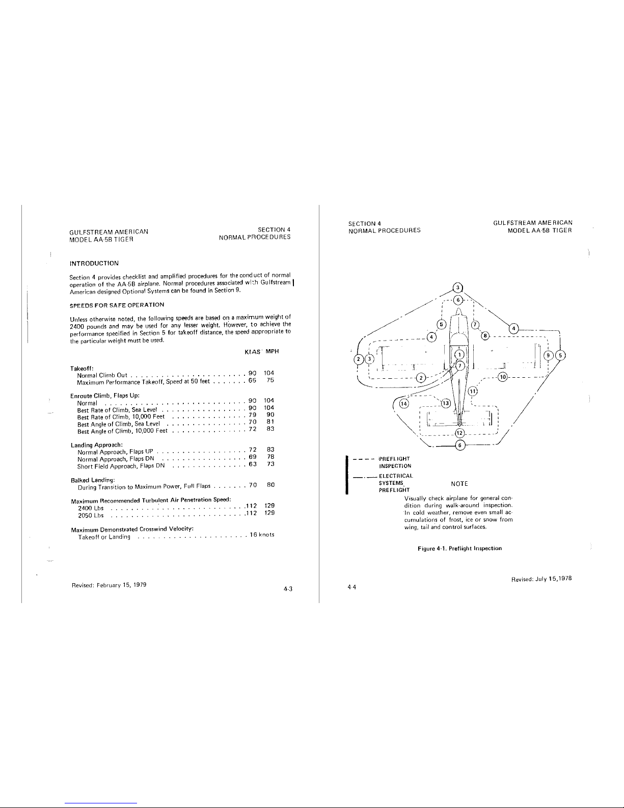
GULFSTREAM
AMERICAN
MODEL
AA·5B
TIGER
INTRODUCTION
SECTION 4
NORMAL
PROCEDURES
Section 4 provides checklist and amplified procedures for the
conduct
of
normal
operation of
the
AA-58 airplane. Normal procedures associated
wi:h
Gu
If
stream I
American designed Optional Systems can be found
in
Section 9.
SPEEDS
FOR
SAFE
OPERATION
Unless otherwise noted the following speeds are based on a maximum weight
of
2400
pounds and may1 be used for any lesser weight.
HOwever,
to
achieve the
performance
specified
in
Section 5 for
takeoff
distance, the speed
appropriate
to
the
particular
weight
must
be used.
Takeoff:
Normal Climb
Out
...............
.
Maximum Performance Takeoff, Speed at
50
feet
Enroute
Climb, Flaps Up:
Normal
Best Rate
of
Climb, Sea
Level
..
Best Rate of C!imb, 10,000 Feet
Best .!\ng!e
of
Climb, Sea
Level
Best Angle
of
Climb, 10,000 Feet
Landing Approach:
Normal Approach,
Flaps
UP
Normal Approach, Flaps ON
Short
Field Approach, Flaps
DN
Balked Landing:
During Transition to Maximum
Power, Full Flaps
Maximum Recommended Turbulent Air Penetration Speed:
2400
Lbs
.
2050
Lbs
......
.
KIAS.
MPH
90
104
65
75
90
104
90
104
79
90
70
81
72
83
72
83
69
78
63
73
...
70
80
.112
129
.112
129
Maximum Demonstrated Crosswind Velocity:
Takeoff
or Landing
.................
16
knots
Revised: February
15, 1979
4.3
SECTION 4
NORMAL
PROCEDURES
GULFSTREAM
AME
RICAN
MODEL
Ak58
TIGER
I
- - - - iPREFLIGHT
INSPECTION
- . - ELECTRICAL
SYSTEMS
NOTE
PREFLIGHT
Visually check airplane for general con·
dition during walk-around inspection.
In cold
weather,
remove even small ac·
cumulations
of
frost,
ice
or
snow
from
wing, tail aiid control surfaces.
Figure
4·1. Preflight Inspection
;
I
Revised: July
15,
1978
44

GULFSTREAM
AMERICAN
MODEL
AA5B
TIGER
CHECKLIST
PROCEDURES
PREFLIGHT
INSPECTION
1.
Cabin
SECTION 4
NORMALPFOCEDURES
(1)
Canopy
- OPEN
{turn
handle
counterclockwise
to
open.)
(2)
Control
Wheel
Lock -REMOVE
(3)
Ignition
Switch --
OFF.
(4) Master Switch - OFF
(5)
Mixture -IDLE
CUTOFF.
2.
Left
Wing
Trailing Edge
(
1)
Flap -Secure
and
undamaged.
(2)
Aileron -Freedom
of
movement
3.
Left
Wing
{ 1)
Win~J
Tip
and
Light --Undamaged
(2)
Aileron
Counterweight
Access -
Unobstructed
(3) Wing
Inspection
Plates - Secure
{4)
Tiedown -Removed
(5)
Pitot
Tube -Unobstructed
(6) Fuel Tank
Vent
- Unobstructed
4.
Left
Wing
Leading
Edge
(1) Fuel Tank - Full, cap
seal
checked for damage,
cap
secure
(2) Tank Drain - Fuel free of water and sediment, drain secure
(3) Sump Drain - Fuel free
of
water and
sediment,
drain
secure
(4)
Fue! -Proper
color
(5)
Landing
Gear
Wheel
Fairing
and
Tire -Undamaged,
tire
properly
inflated
(6)
Chocks -Removed
5.
Left
Cowl
(1)
Windshield -Clean,
undamaged
(2)
OAT
Gauge -Secure,
undamaged
(3)
Fuel
Pump
Overflow
Drain -Unobstructed
(4)
Fresh
Air
Vents -Unobstructed
(5)
Air
Cleaner
Drain -Unobstructed
{6}
Oil
Breather
Vent --Unobstructed
Revised:
December
15,
1977
I
I
I
SECTION
4
GULFSTREAM
AMERICAN
MODEL
AA
5B
TIGER
NORMAL
PROCEDURES
(7)
Cowling -Open,
secured
(8)
Baffles -Secure,
undamaged
(9)
Cowling -Closed,
latches
secured
(Hush
with
surface)
NOTE
If
engine
cowl
is
opened,
ensure
that
its
support
tube
is
secured
in
th~
retainer
clip
prior
to
closing
the
cowl.
Ensure
that
cowl
latches
are
secure
{flush
with
surface).
6.
Nose
(1)
Propeller
and
Spinner
-Secure,
undamaged
(2)
Cowling
-·
Secure,
undamaged
(3)
Landing
Light -Secured,
undamagecl
(4)
Nose
Gear,
and
Fairing -Undamaged,
tire
properly
inflated,
rnud
scraper
clear
(5)
Tow
Bar -
Removed
and
stowed
(6)
Chocks -Rernoved
(7)
Engine
Cooling
Openings -Unobstructed
7.
Right
Cowl
i1)
Cowl -Open
(2)
Engine
Baffles -Unobstructed,
undarnaged
(3)
Carburetor
Air
Duct -Unobstructed
(4)
Engine
Cooling
Openings -Unobstructed
(5)
Engine
Oil Level - 6
Quarts
minimum,
capacity B quarts
(6)
Engine
Oil
Dipstick -Secured
{finger
tight)
{7)
Vacuum
Pump
Vent -Unobstructed
(8)
Battery -Secure
(9)
Alternator
Belt -Proper
tension
( 10)
Baffles -Secured,
Undamaged
j 11)
Cowl -Closed,
latches
secured
{flush
with
surface)
B.
Right
Wing
Leading
Edge
46
(l)
Fuel
Tank -Full,
cap
seal
checked
for
damage,
cap
secured
(2)
Tank
Drain -Fuel
free
of
water
and
sediment,
drain
secured
(3)
Surnp
Drain -Fuel
free
of
water
and
sediment,
drain
secure
(4)
Fuel -Proper
color
(5)
Landing
Gear,
Wheel
Fairing
and
Tire -Undarnagerl,
tire
properly
in-
flated
Revised:
December
15,
1977
 Loading...