

Gulfstream Aerospace 1977 AA·5A CHEETAH, 1978 AA·5A CHEETAH, 1979 AA·5A CHEETAH Pilot Operating Handbook

I
",I
I
I.
I
II
if
I'
: I
,
~
(--......
L
Ii'
"
.-'
PILOT'S OPERATING HANDBOOK
t·
Model AA·5A'CHEETAH
1977
1197~
11979
THIS HANDBOOK INCLUDES THE MATERIAL
REQUIRED
TO
BE
FURN~SH~9
TO
TI1E
PILOT
BY
FA~
PART
23.
SERIAL~O.
__
--.-
__
--..,-
__
REGISTRATION NO.
____
_
J
'QII
Gulfstream
~e
Corporation
Ac:arraa
91MPANY
Savannah, Georgie,
U.S.A.
Issued: January
15,
1977
Revision
4:
March
2,
1988
©
1988
Gulfstream Aerospace Corporation
All
rights reserved, including the right
to
reproduce
this
publication.
No
part
may
be reproduced, stored in any retrieval system, or transmitted in any
part
or
form
or by any means, electronic,
photoCopying, microfilm, microfiche, mechanical,
or
otherwise, without prior written
pe~mission
of Gulfstream Aerospace Corporation.
'.
GULFSTREAMAEROSPACE
MODEL AA·5A
CH
EEl
AH
LIST OF EFFECTIVE PAGES
LIST OF EFFECTIVE PAGES
Dates of Issue for original and revised pages are:
Original ............. 0
••.......•.
January
15,
1977
Revision ............ 1 ............ Docember
15,
1977
RevisiOn
...••..•.•••
2 ............
July
15,
1978
Revision ............ 3 ............ February
15,
1979
Revision ............ 4 ..........
,.'
March
2,
1988
THE
TOTAL NUMBER OF PAGES IN THIS HAt-lDBOOK IS
181,
CONSISTING OF THE
FOLLOWING. THIS INCLUDES THE
SUPPLEM~NTS
PROVIDED IN SECTION 9 WHICH
COVER OPTIONAL
SYSTEt.!IS
AVAILABLE IN THE AIRPLANE.
Page
No.
•
Revision
No.
Title .................................................... 4
A ........................................... : ............. 4
B ......................................................... 4
I ........................................................... 3
II
thru III ............................................. 0
Iv
......................................................... 3
1·1
thru
1·2
........................................ 0
1·3
......................................... : ............. 3
L
1·4
................................ : ...................... 1
" 1·5 thru 1·12 ...................................... 0
2·1
....................................................... 0
2:2
Blank ........................................... 0
2·3
....................................................... 3
2·4
thru
2·5
........................................ 0
2-6
....................................................... 4
2·7
thru
2·8
........................................ 0
2·9
thru
2·12
...................................... 1
3·1
thru
3·4
........................................ 0
3·5
....................................................... 2
3·6
thru
3-17
...................................... 0
3·18
..................................................... 1
4·1
thru
4·2
........................................ 0
4·3
................................................ ;
....•.
3
4·4 thru
4·7
•••............... : ..................... 0
4·8
thru 4·9 ........................................ 1
4·10 .............................
::-.
...................
:.
0
4·11
..................................................... 1
."
4·12 ..................................................... 0
4,,13
..................................................... 1
l 4·14 thru
4·21
.................................... 0
'-.I
4·22 ..................................................... 1
Page
No.
"Revision
No.
4·23 ..................................................... 0
4·24
..................................................... 1
4·25 ..................................................... 0
4·26 Blank
......................................... 0
5·1
....................................................... 0
5·2 Blank ........................................... 0
5·3
thru
5·14
.•..••••..•.....•.............•....... 0
5·15
...........
i:
........................................
4
5·16
thru 5·18 .................................... 0
5·19
..................................................... 2
5·20 ..................................................... 0
5·21
..................................................... 2
5·22 thru 5·25 ...........•........................ 0
5·26
Blank ..............•.•.....• ; ................. 0
6·1
....................................................... 0
6·2 Blank ........................................... 0
6-3
thru 6-15 ...................................... 0
6-16
..................................................... 3
6·17
..................................................... 0
, 6-18
thru 6-19 .................................... 1
6-20 Blank ......................................... 0
7·1
thru
7·4
........................................ 0
7·5
........................................................ 1
7·6
thru 7·15 ........................ : ............. 0
'.
7·16 thru 7·16a .................................. 1
.
7·16b Blank ....................................... 0
, 7·17
thru 7·24 .................................... 0
8·1
....................................................... 0
..
8·2
Blank ........................................... 0
8·3
thru 8·5 ........................................ 3
,
8·6
thru 8·14 ...................................... 0
• Zero .In
this
column Indicates original page.
Revised: March
2,
1988 A
LIST
OF
EFFECTIVE
PAGES
Page
No.
• Revision
No.
9-1
....................................................... 0
9-2
Blank ........................................... 0
9·3
....................................................... 0
9-4
Blank ........................................... 0
10-1
thru
10-2
.................................... 0
10-3
..................................................... 3
104
thru
10-7
.................................... 0
10-8
..................................................... 2
10-9
thru
10-16
.................................. 0
• Zero
In
this column Indicates
an
original page.
B
GULFSTREAM
AEROSPACE
MODEL
AA·5A
CHEETAH
Revised: March
2,
1968
),
)~
(
GULFSTREAM
AMERICAN
.",~PEL
AA·5A
CHEETAH
WELCOME
ABOARD!
WE
LCOME
ABOARD
Your
AA·5A
Cheetah
has
been
designed
and
constructed
to
provide
you
with
a
responsive
four·place
airplanE!
to
serve
combortably
and
economically
your
needs
for
either
pleasure
or
busine~s.
flying.
This
handbook
has
been
prepared
to
help
you
obtain
the
maximum
pleasure
and
utility
from
your
airplane.
Read
it
carefully,
review it
frequently,
and
keep
it
with
you
in
the
airplane
at
all
times.
With
proper
operational
techniques
and
good
maintenance,
your
Gulfstream
I
American
Cheetah
should
serve
you
well.
Get
to
know
your
Gulfstream
American
Dealer. He
is
equipped
to
provide
any
assistance
that
may
be
required.
Revised:
February
15,
1979
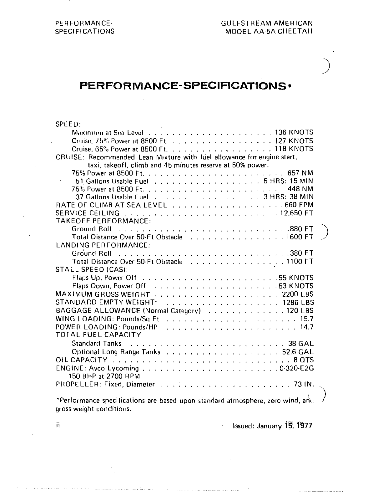
PERFORMANCE·
SPECIFICATIONS
GU
LFSTREAMAME
RICAN
MODEL
AA·5A
CHEETAH
PERFORMANCE-SPECIFICATIONS-
SPEED:
MaxillllHll
at
SI~<l
Level 136 KNOTS
Cruise,
IlJ"u
Power
at
8500 FI.
127
K~IOTS
Cruise, 65"0 Power at 8500 FI. 118 KNOTS
CRUISE:
Recommended
Lean
Mixture
with
fuel allowance
for
engine start,
taxi, takeoff, climb
ann
45 minutes
reserve
at
50%
power.
75%
Power
at
8500 FI. . .
...
657 NM
51
Gallons USilble Fuel . . . 5 HRS: 15
MIN
75%
Power
at
8500 Ft. . . . . .
...
448 NM
37
Gallons Usable Fuel . . . 3 HRS: 38
MIN
RATE
OF
CLIMB
AT
SEA
LEVEL
..
660 FPM
SERVICE
CEILING.
. . . .
.12,650
FT
TAKEOFF
PERFORMANCE:
)
Ground Roll
.....
.
Total Distance
Over 50· F t Obstacle
LANDING
PERFORMANCE:
·
.880
Fl
').
· 1600 FT
Ground
Roll
...........
.
Total Distance Over 50·Ft Obstacle
STALL
SPEED (CAS):
Flaps Up, Power
Off
...
Flaps Down, Power
Off
MAXIMUM
GROSS
WEIGHT.
STANDARD
EMPTY WEIGHT:
BAGGAGE
ALLOWANCE
(Normal Category)
WING
LOADING:
Pouncls/Sq Ft
POWER
LOADING:
Pounds/HP
TOTAL
FUEL
CAPACITY
Standard Tanks
.....
.
Optional Long
Range
Tanks
01
L
CAPACITY
.....
.
ENGINE: Avco Lycoming
..
.
150
BHP
at
2700
RPM
PROPELLER: Fixed, Diameter
·
.380
FT
· 1100 FT
.55
KNOTS
.53
KNOTS
2200
l.BS
1286 l.BS
.120
l.8S
15.7
..
14.7
38
GAl.
52.6
GAL
· .
80TS
.0·320·E2G
...
73
IN.
• Performance specifications
are
based
upon stanrlarn atmosphere, zero wind,
a~l.
gross
weight conditions.
ii
Issued: January
f!:f;
1977
)
i
I
\.
.•
9\;L~FSTREAM
AMERICAN
MODEL
AA·5A
CHEETAH
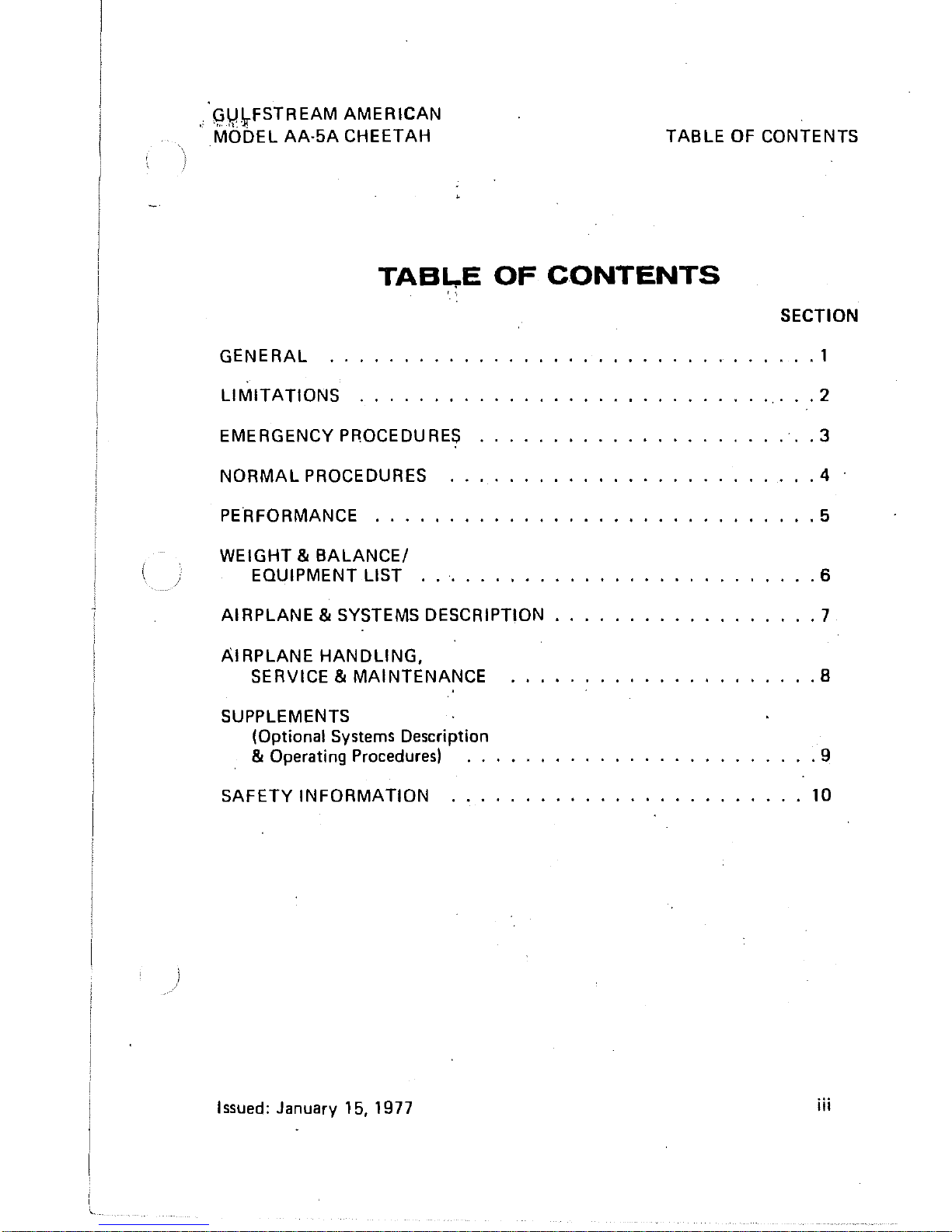
TABLE
OF CONTENTS
TAB~E
OF
CONTENTS
GENERAL
.,
LIMITATIONS
EMERGENCY PROCEDURES
NORMAL
PROCEDURES
PERFORMANCE
...
WEIGHT &
BALANCE/
EQUIPMENT LIST
AIRPLANE
& SYSTEMS DESCRIPTION
AIRPLANE
HANDLING.
SERVICE &
MAINTENANCE
SUPPLEMENTS
(Optional
Systems
Description
& Operating Procedures)
SAFETY
INFORMATION
.....
.
I ssued:
January
15.
1977
SECTION
. 1
.2
.3
.4
.5
.6
.7
.8
.9
10
iii
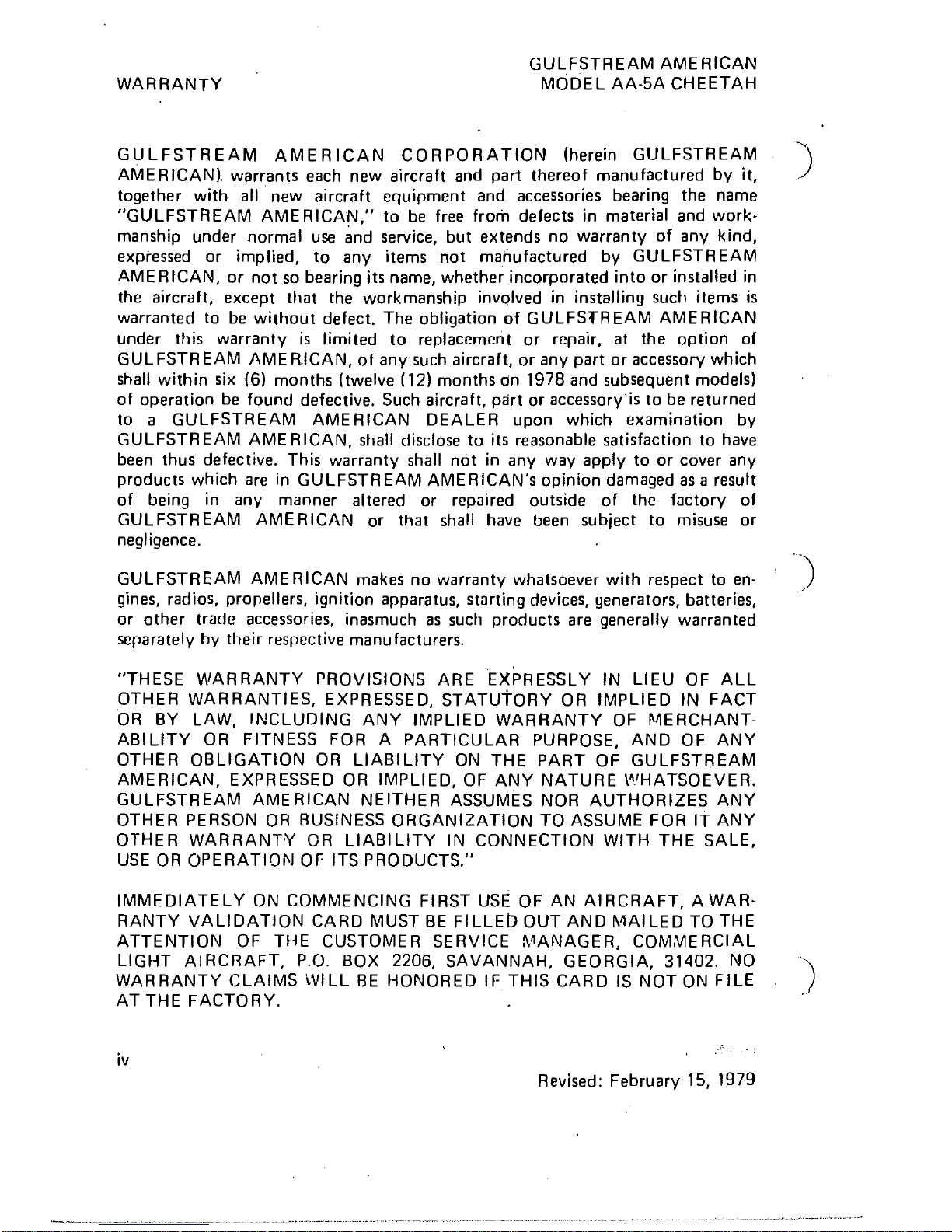
WARRANTY
GULFSTREAM
AMERICAN
MODEL
AA-5A CHEETAH
GULFSTREAM
AMERICAN
CORPORATION
(herein GULFSTREAM
~)'
AME
RICAN), warrants each new aircraft and part thereof manufactured by it,
together with
all
new aircraft equipment and accessories bearing the name
"GULFSTREAM AMERICAN," to be free from defects
in
material and workmanship under normal use and service, but extends no warranty of any kind,
expressed or
implied,
to
any items not manufactured by GULFSTREAM
AMERICAN,
or
not
so
bearing its name, whether incorporated into or installed
in
the aircraft, except thilt the workmanship involved
in
installing such items
is
warranted to
be
without defect. The obligation
of
GULFS'fREAM AMERICAN
under this warranty
is
limited
to
replacement
or
repair, at the option of
GUL
FSTR
EAM
AME
R.ICAN,
of any such aircraft, or any part
or
accessory which
shall within
six
(6) months (twelve (12) months dn 1978 and subsequent models)
of operation be found defective. Such aircraft, part or accessory
is
to
be returned
to a GULFSTREAM
AMERICAN DEALER upon which examination by
GULFSTR
EAM
AME
RICAN, shall disclose
to
its reasonable satisfaction to have
been thus defective. This warranty shall
not
in
any way apply to
or
cover any
products which are
in
GULFSTREAM AMERICAN's opinion damaged
as
a result
of being
in
any manner altered or repaired outside of the factory of
GULFSTREAM
AMERICAN or that shall have been subject to misuse
or
negligence.
GULFSTREAM
AMERICAN makes no warranty whatsoever with respect to
en-
)
gines, radios, prorellers, ignition apparatus,
st<Jrting
devices, generators, batteries,
or
other
trade accessories, inasmuch
as
such products are generally warranted
separately by their respective manufacturers.
"THESE WARRANTY PROVISIONS ARE EXPRESSLY
IN
LIEU
OF
ALL
OTHER WARRANTIES, EXPRESSED,
STATUtORY
OR
IMPLIED
IN
FACT
OR
BY
LAW,
INCLUDING ANY IMPLIED WARRANTY
OF
~~ERCHANT
ABI
LlTY
OR
FITNESS FOR A PARTICULAR PURPOSE, AND OF ANY
OTHER OBLIGATION
OR
LIABILITY
ON
THE PART OF GULFSTREAM
AMERICAN, EXPRESSED
OR
IMPLIED,
OF
ANY NATURE
t~/HATSOEVER.
GULFSTREAM
AME
RICAN NEITHER ASSUMES
NOR
AUTHORIZES ANY
OTHER PERSON
OR
AUSINESS ORGANIZATION TO ASSUME FOR
IT
ANY
OTHER WARRANTY
OR
LIABILITY
IN
CONNECTION
WITH
THE SALE,
USE
OR
OPERATION
Or-
ITS
PRODUCTS."
IMMEDIATELY
ON
COMMENCING FIRST
USE
OF
AN
AIRCRAFT, A
WAR-
RANTY VALIDATION CARD
MUST
BE
FILLED OUT AND MAILED
TO
THE
ATTENTION
OF
THE CUSTOMER SERVICE
i\~ANAGER,
COMMERCIAL
LIGHT AIRCRAFT, P.O.
BOX
2206, SAVANNAH, GEORGIA, 31402.
NO
")
WARRANTY CLAIMS WILL
FlE
HONORED
IF
THIS CARD
IS
NOT
ON
FILE
AT
THE FACTORY. .
iv
Revised: February 15, 1979
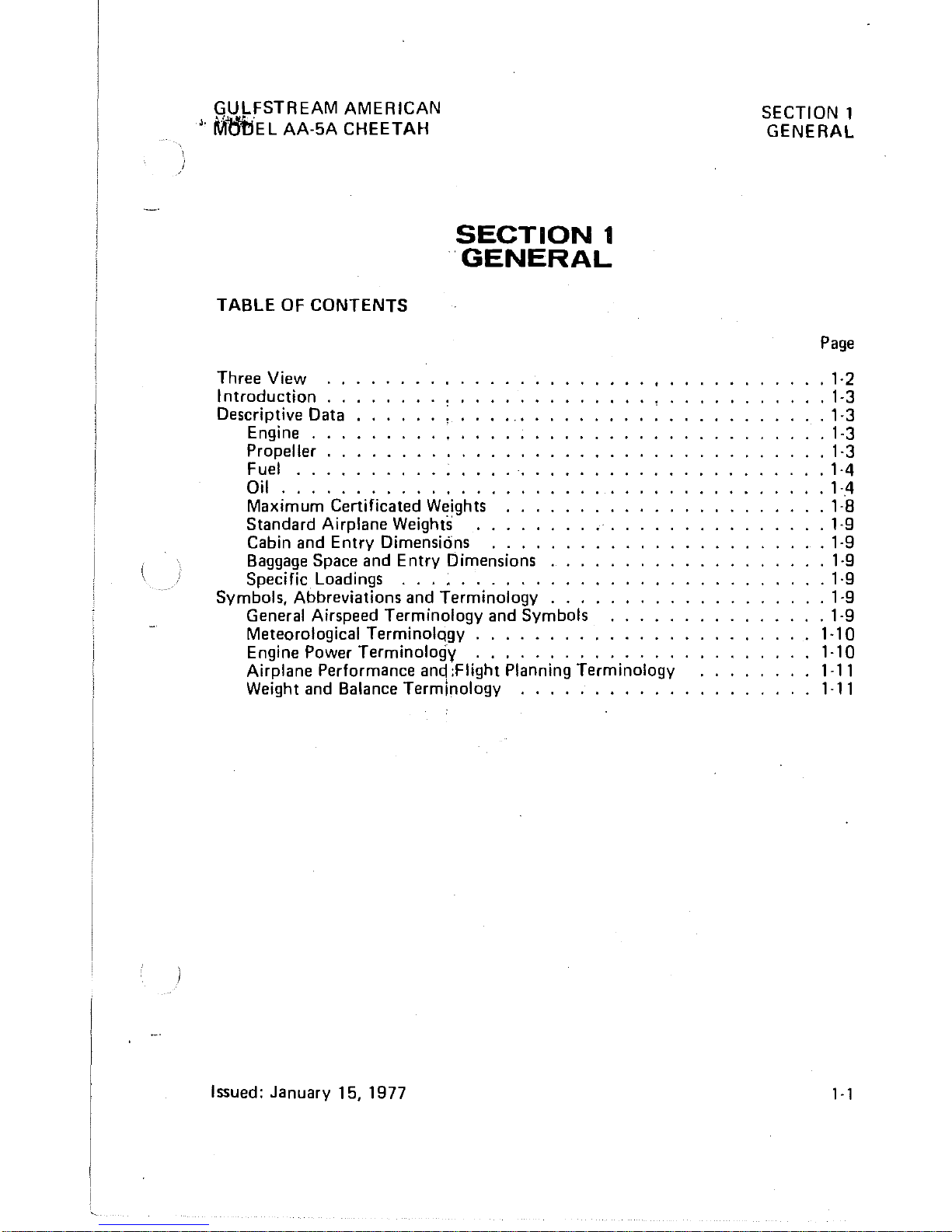
GULFSTREAM AMERICAN
J,
M6bEL
AA-5A CHEETAH
TABLE
OF
CONTENTS
Three View "
Introduction , ,
Descriptive Data
Engine,
,
Propeller , ,
Fuel
....
SECTION
1
'GENERAL
Oil
. , . , ,
..
, . , "
..
Maximum Certificated Weights
Standard
Airplane Weights
Cabin and Entry Dimensions . .
Baggage
Space and Entry Dimensions
Specific Loadings
.........
.
Symbols, Abbreviations and Terminology
...
General Airspeed Terminology and Symbols
Meteorological TerminolQgy
........
.
Engine
Power Terminologv
..........
,.
Airplane Performance and :Flight Planning Terminology
Weight and Balance Terminology
..........
.
Issued: January 15, 1977
SECTION 1
GENERAL
Page
.1·2
,1-3
· 1-3
.1-3
· 1·3
· 1-4
·
1-,4
· 1·8
· 1·9
.1-9
· 1·9
.1·9
.1-9
.1-9
1-10
1·10
1-11
1·11
,-,
SECTION 1
GENERAL
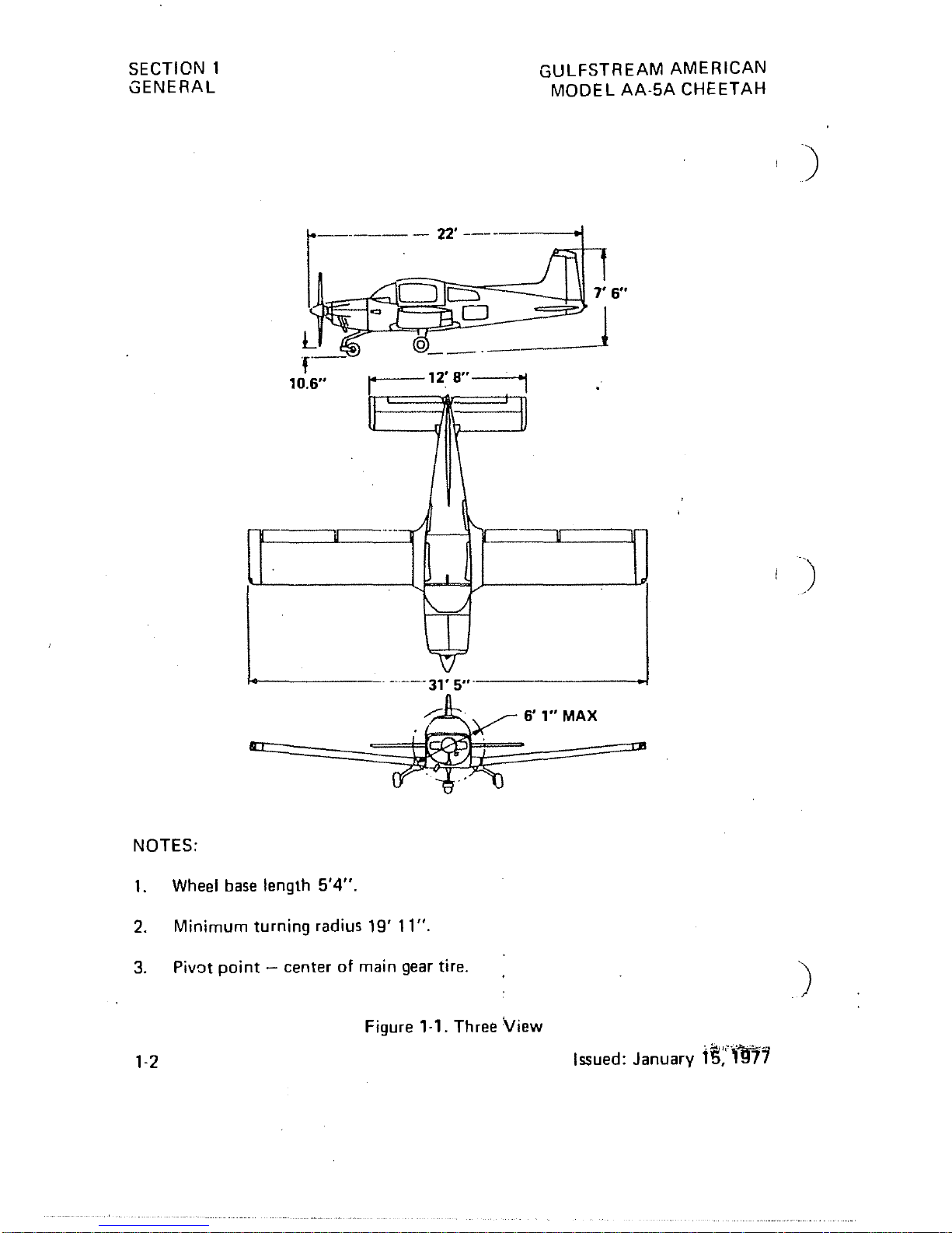
NOTES:
1.
Wheel base length
5'4".
2. Minimum
turning
radius
19'
11".
3. Pivot
point -center
of
main gear tire.
GULFSTREAM
AMERICAN
MODEL
AA-5A
CHEETAH
Figure
,-,.
Three
View
1-2
Issued:
January
lS;'""fft"j1
)
)
GULFSTREAM AMERICAN
~
',"IJl!'\QDEL
AA-5A CHEETAH
INTRODUCTION
SECTION
1
GENERAL
The ten sections of this
hanqbook contain the information needed by the pilot I
for safe and efficient oper9't;on of the Gulfstream American Model AA-5A
air-
planes_
This handbook also includes the material required to be furnished to the
pilot
by FAR, Part 23, and supplernef]tal data covering Gulfstream American
designed
optional equipment installed
in
the airplane.
Section 1 provides basic data and information of general interest to the pilot, to
assist him
in
loading, shelteiing, handling, and routine preflight checking of the
airplane. Also included
in
this section are definitions and explanations of the
symbols, abbreviations and terminology used
in
this handbook.
DESCRIPTIVE DATA
ENGINE
NOTE
Unless otherwise noted,
all
perfor-
mance and operational data
in
this
book are
based on
sea
level, standard
day, and airplane gross weight conditions.
Number
of
Eng'ines:
Manufacturer: Avco Lycoming
Model Number: 0-32D-E2G
Type: Normally-aspIrated, direct-drive, air-cooled, horizontally-opposed,
carburetor
equipped, four-cylinder engine with 319.8 cubic inch
displacement:
Horsepower Rating and Engine Speed: 150
HP
at
2700
RPM
PROPELLER
Manufacturer:
McCauley
Model
Number: 1 C 172/BTM7359
Diameter:
73
inches
Type: Fixed
Pitch
Revised: February 15, 1979
1-3
SECTION 1
GENERAL
GULFSTREAM
AMERICAf\
MODEL AA-5A CHEETAF
FUEL
CAUTION
UNDER
NO
CIRCUMSTANCES
SHOULD FUEL OF A
LOWER
OC·
TANE RATING THAN THAT SPECI·
FlED
BELOW,
OR
AUTOMOTIVE
FUEL (REGARDLESS
OF
OCTANEI
BE
USED.
Grade (and
colod:
80/87 Minimum Grade Aviation Fuel (redl 100 Low Lead
Aviation
Fuel (bluel
is
also approved. Refer 10 the latest revision of Lycoming
Service
Instruction No.
1070
for further information concerning fuels.
Capacity
at
an
ambient temperature of 70'F (21°CI:
Standard Tanks:
Total: 38 U.S. Gallons
(31~6
Imperial Gallonsl (143.8 Litersl
Each Tank:
19
U.S. Gallons (15.8 Imperial Gallonsl (71.9 Litersl
Total Usable:
37 U.S. Gallons (30.8 Imperial Gallons) (140 Liters)
Optional
Long Range Tanks
I Total: 52.6 U.S. Gallons (43.8 Imperial Gallons) (199.0 Liters)
Each Tank: 26.3 U.S.
Gallons (21.9 Imperial Gallonsl (99.5 Liters)
Total Usable:
51
U.S. Gallons (42.5 Imperial Gallons) (193 Liters)
OIL
Grade (Specification):
1·4
Aviation Grade Straight Mineral
Oil
MIL·L·6b82 (Figure 1·2) shall
be
used to
replenish oil supply during the first 25 hours of operation and
at
the first
25·hour
oil change. Continue to use this grade of
oil
for a minimum of first
50 hours
of
or until oil consumption has stabilized.
NOTE
The airplane
is
delivered from the fac·
tory' with corrosinn preventive airplane
I!~:qine
oil. This oil should be drained
after
tile first 25 hours of engine opera·
tion.
MI
L·L·22851 (Figure 1·2) Ashless Dispersant Oil: This specification oil shall
bl::
used after the rirst
50
hours of engine operation.
Revised: December
15,'''-971''
)
)
)
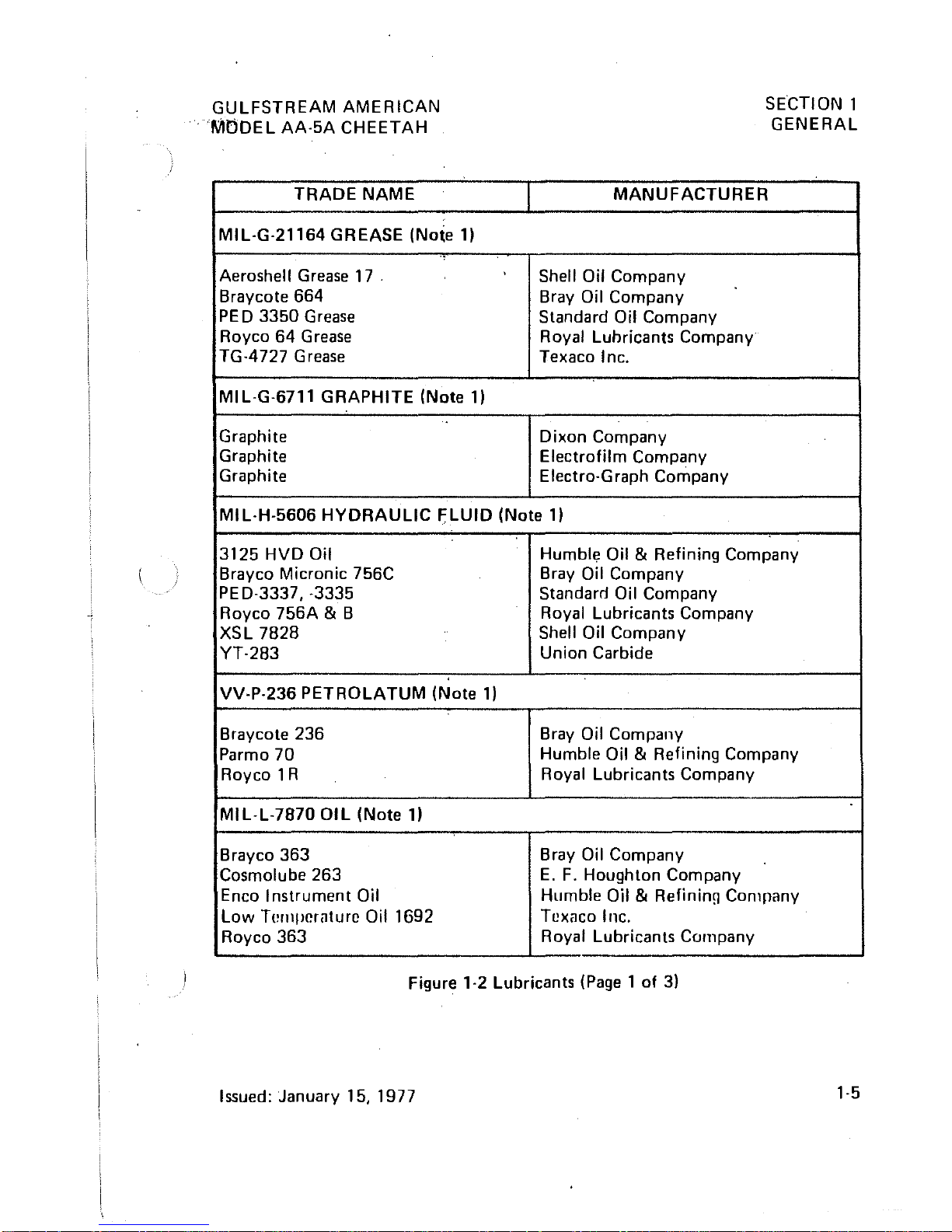
GULFSTREAM
AMERICAN
MODEL
AA-5A
CHEETAH
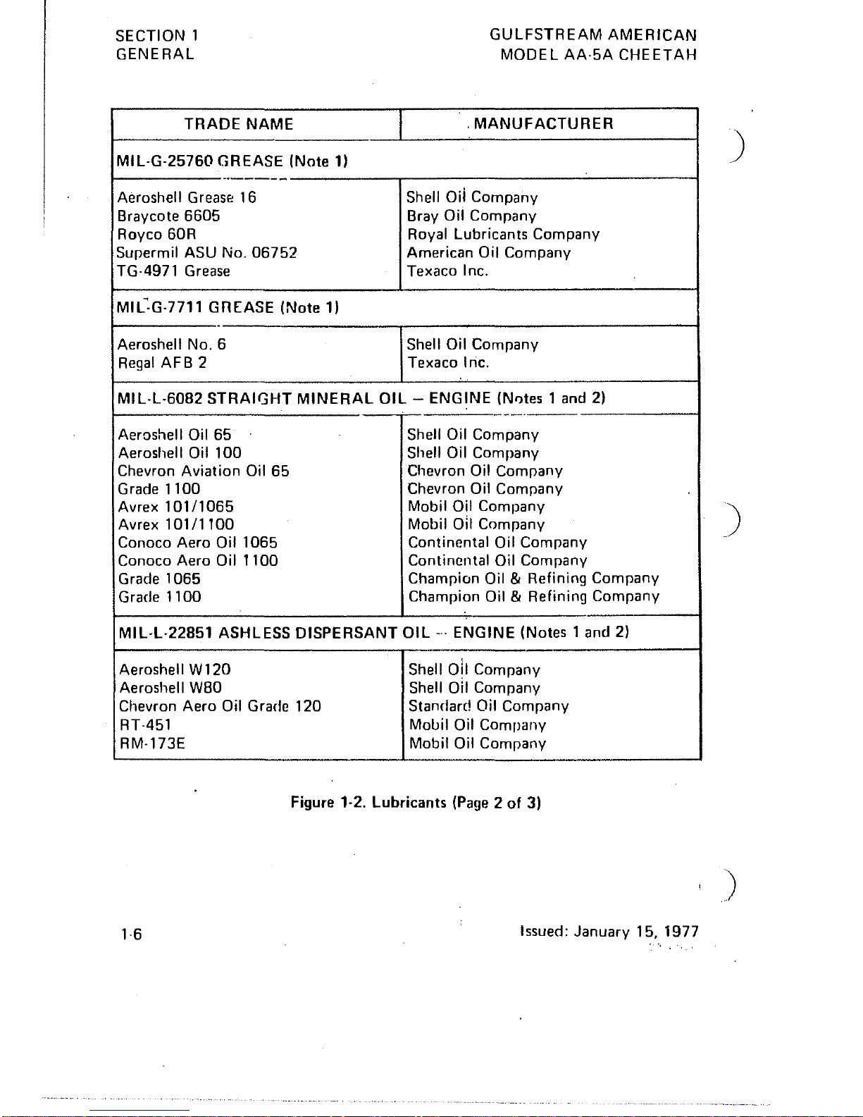
TRADE
NAME
MIL-G-21164 GREASE (Note
1)
Aeroshell
Grease
17
.
Braycote 664
PED
3350
Grease
Royco 64
Grease
TG-4727
Grease
MIL-G-6711
GRAPHITE
(Note
1)
Graphite
Graphite
Graphite
SECTION 1
GENERAL
MANUFACTURER
Shell Oil Company
Bray Oil Company
Standard Oil Company
Royal
Luhricants Company
Texaco Inc.
Dixon Company
Electrofilm Company
Electro-Graph Company
MIL·H-5606
HYDRAULIC
FLUID
(Note
1)
3125
HVD
Oil Humblt:! Oil & Refining Company
Brayco Micronic 756C Bray Oil Company
PE
D-3337, -3335
Standard Oil Company
Royco
756A
& B
Royal Lubricants Company
XSL 7828
Shell Oil Company
YT-283
Union
Carbide
VV-P-236
PETROLATUM
(Note
1)
Braycote 236 Bray Oil Company
Parmo 70
Humble Oil
& Refining Company
Royco 1 R
Royal Lubricants Company
MIL-L-7870
OIL
(Note
1)
Brayco 363 Bray Oil Company
Cosmolube
263
E.
F.
Houghton Company
Enco Instrument Oil
Humble Oil
& Refinin[l Comrany
Low
TelllpcrClture Oil 1692
Texaco Inc.
Royco 363
Royal Lubricants Company
Figure 1-2 Lubricants
(Page
1 of 3)
Issued: January 15, 1977
1-5
SECTION
1
GENERAL
TRADE
NAME
MIL·G-2576(l
GREASE
(Note
1)
~
..
-----
Aeroshell
Grease
16
Braycote
6605
Royco
60R
Supermil
ASU
No.
06752
TG-4971
Grease
MIL-:G·7711
GnEASE
(Note
1)
Aeroshell
No.6
Regal
AFB
2
GULFSTREAM
AMERICAN
MODEL
AA-5A
CHEETAH
.
MANUFACTURER
Shell
oii
Company
Bray Oil
Company
Royal
Lubricants
Company
American
Oil
Company
Texaco
Inc.
Shell Oil
Company
Texaco
Inc.
MIL·L·6082
STRAIGHT
MINERAL
OIL -ENGINE
(Nl)tes 1
and
2)
-_._--
Aeroshell
Oil
65
Shell Oil
Company
Aeroshell
Oil
100
Shell Oil
Company
Chevron
Aviation
Oil
65
Chevron
Oil
Company
Grade
1100
Chevron
Oil
Company
Avrex
101/1065
Mobil Oil
Company
Avrex
101/1100
Mobil
011
Company
Conoco
Aero
Oil
1065
Continental
Oil
Company
Conoco
Aero
Oil
1100
Continental
Oil
Company
Grade
1065
Champion
Oil &
Refining
Company
Grade
1100
Champion
Oil &
Refining
Company
MIL·L·22851
ASHLESS
DISPERSANT
OIL
...
ENGINE
(Notes 1 and
2)
Aeroshell W 120
Shell
oil
Company
Aeroshell
wao
Shell Oil
Company
Chevron
Aero
Oil
Grade
120
Standard
Oil
Company
RT-451
Mobil Oil
Company
RM-173E Mobil Oil
Company
Figure
1·2.
Lubricants
(Page 2
of
3)
1·6
Issued:
January
15,
1977
)
)
)

GULFSTREAM
AMERICAN
M.QJ;l.EL
AA·5A
CHEETAH
TRADE
NAME
SECTION 1
GENERAL
MANUFACTURER
MIL·L·22851
ASHLESS
DISP-ERSANT
OIL -ENGINE
(Notes 1 and
2)
(Cont.)
RM·180E
Mobil Oil
Company
TX·6309
Texaco
Inc.
Premium
AD
120
Texaco
Inc.
Premium
AD
80
Texaco
Inc.
Oi1E·120
Exxon
Company
Oil
A·l00
Exxon
Company
Oil
E·80
Exxon
Company
Note
1:
The
vendor
products
listed
in
this
chart
have
been
selected as
representative
of
the
specification
under
which
they
appear.
Other
equivalent
products'
conforming
to
the
same
specifications
may
be used.
Note
2:
Oils
conforming
to
the
latest
revision
of
Lycoming
Service
Instruction
No.
1014
may
be
u~l:!d.
Figure
1·2
Lubricants
(Page 3
of
3)
Issued:
January
15,
1977
1·7
SECTION 1
GENERAL
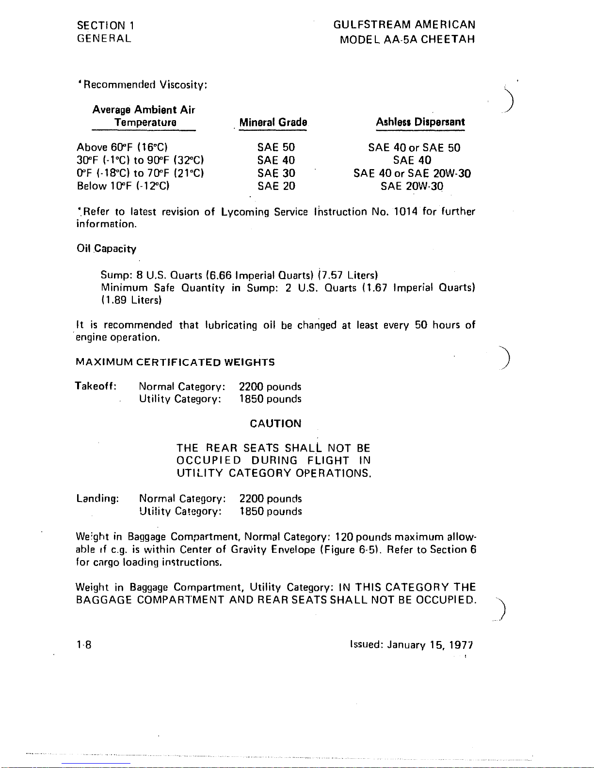
'Recommended
Viscosity:
Average Ambient Air
Temperature
Above
60"F
(16°C)
30"F (-l°C)
to 90"F (32"C)
O"F
(-l8"C)
to
70"F
(21
DC)
Below 1
O"F
(-l2"C)
. Mineral
Grade
SAE
50
SAE
40
SAE
30
SAE
20
GULFSTREAM AMERICAN
MODEL
AA-5A CHEETAH
Ashlesl Dispersant
SAE
40
or
SAE
50
SAE
40
SAE
40
or SAE 20W-30
SAE
20W-30
'.
Refer to latest revision
of
Lycoming Service Instruction
No_
1014 for further
information_
Oil
Capacity
Sump: B
U.S.
Quarts (6.66 Imperial Quarts) i7.57 Liters)
Minimum Safe Quantity
in
Sump: 2
U.S.
QUarts (1.67 Imperial Quarts)
(1.89 Liters)
It
is
recommended
that
lubricating oil
be
changed at least every 50 hours of
. engine operation.
MAXIMUM
CERTIFICATED
WEIGHTS
Takeoff:
Landing:
Normal Category:
Utility Category:
2200 pounds
1850 pounds
CAUTION
THE
REAR SEATS SHALL
NOT
BE
OCCUPI
E D DURING FLIGHT
IN
UTILITY CATEGORY OPERATIONS.
Normal Category:
Utility Category:
2200
pounds
1850 pounds
We'ght
in
Baggage
Compartment, Normal Category: 120 pounds maximum allow-
able
If
C.g.
is
within Center of Gravity Envelope (Figure 6-5l. Refer to Section 6
for cilrgo loading
in~tructions.
Weight
in
Baggage Compartment, Utility Category:
IN
THIS CATEGORY THE
BAGGAGE
COMPARTMENT
AND
REAR SEATS SHALL
NOT
BE
OCCUPIED.
Issued:
January 15, 1977
)
)
GULFSTREAM
AMERICAN
;,.
MODEL
AA·5A
CHEETA!"I
STANDARD
AIRPLANE
WEIGHTS
NOTE
Actu,,1
weights for
each
airplane
will
vary,according
to
installed
equipment.
Refer
to
weight
and
balance
data
sup-
plied
with
the
particular
airplane
for
specific
data
for
that
airplane.
Standard
Empty
Weight:
1286
Ibs.
Maximum
Useful
Load:
t-lormal
Category:
9141bs.
Utility
Category:
5541bs.
CABIN
AND
ENTRY
DIMENSIONS
SECTION
1
GENERAL
Detailed
dimensions
of
the
cabin
interior
and
canopy
opening
are
provided
in
Section
6. '
BAGGAGE
SPACE AND
ENTRY
DIMENSIONS
Baggage area
and
access
dimensions
are
provided
in
Section
5.
SPECI FIC
LOADINGS
Wing Loading:
Power
Loading:
15.7
pounds
per
square
foot
14.7
pounds
per
B.H.P.
SYMBOLS,
ABBREVIATIONS
AND
TERMINOLOGY
GENERAL
AIRSPEED
TERMINOLOGY
AND
SYMBOLS
KCAS
KIAS
KTAS
Knots
Calibrated
Airspeed
is
indicated
airspeed
corrected
fOI
position
and
instrument
error
and
expressed
in
knots.
Knotl
calibra~~d
airspeed
is
equal
to
KTAS in
standard
atmosphere
at
sea
lev~1.
Knots
Indicated
Airspeed
is
the
speed
shown
on
the
outer
scalE
of
the
~irspeed
indicator
and
expressed
in
knots.
Knots
True
Airspeed
is
the
airspeed
expressed
in
knots
relativ!
to
undisturbed
air
which
is
KCAS
corrected
for
altitude
am '
temperature.
Issued:
January
15,
1977
1-[

SECTION
1
GENERAL
VFE
103
VNO
la9
vNE
/(,1
Vs
5:5
Vs
0
53
Vx
6S
GULFSTREAM
AMERICAN
MODEL
AA-5A
CHEETAH
Maneuvl!ring
Speed
is
the
maximum
speed
at
which
application
of
full <lvailable
control
will
not
overstress
the
airplane.
Maximum
Flap
Extended
Speed
is
the
highest
speed
permissible
at
which
wing flaps
can
be
extended.
Maximum
Structural
Cruising
Speed
is
the
speed
that
should
not
be
exceeded
except
in
smooth
air.
then
only
with
caution.
Never
Exceed
Speed
is
the
speed
limit
that
may
not
be
ex-
ceeded
ilt
any
time.
Stalling
Speed
(Clean)
is
the
minimum
steady
flight
speed
at
which
the
airplane
is
controllable_
Stalling
Speed
(Landing)
is
the
minimum
steady
flight
speed
at
which
the
airplane
is
controllable
in
the
landing
configuration.
Best Angle-of-Climb
Speed
is
the
speed
which
results
in
the
greatest
gain
of
altitude
in
a given
liorizontal
distance.
)
Vy
19
Best
Rate-of-Climb
Speed
is
the . speed
which
results
in
the
)
greatest
gain
in
altitude
in a given time_
METEOROLOGICAL
TERMINOLOGY
OAT
Standard
Temperature
Pressure
Altitude
Outside
Air
Temperature
is
the
free air
static
temperature.
It
is
expressed
in
either
degrees Celsius
(Centigrade)
or
degrees
Fahrenheit.
Standard
Temperature
is
15°C
(~9°F)
at
sea level
pressure
altitude
and
decreases
by
2°C
(4~F)
for
each
1000
feet
of
altitude.
Pressure
Altitude
is
the
altitude
read
from
an
altimeter
when
the
barometric
subscale has
been
set
to
29.92
inches
of
mercury
(1013
mb).
ENGINE
POWER
TERMINOLOGY
BHP
RPM
1-10
Brake
Horsepower
is
the
power
developed
by
the
engine.
Revolutions
Per
Minute
is
engine
speed
(number
of
revolutions
engine
turns
per
minute).
.
Issued:
January
15.
1917
')
GULF~TREAM
AMERICAN
"
MobEt'AA.5A
CHEETAH
SECTION
1
GENERAL
AIRPLANE
PERFORMANCE
AND
FLIGHT
PLANNING
TERMINOLOGY
Demonstrated
Crosswind
Velocity
Usable Fuel
Unusable
Fuel
GPH
g
Demonstrated
Crosswind
Velocity
is
the
velocity
of
the
crosswind
component
for
which
adequate
control
of
the
airplane
during
takeoff
and
landing was
actually
demonstratef;!
during
certification
tests.
Usable Fuel
is
the
fuel available for flight.
Unusable
Fuel
is
the
quantity
of
fuel
that
cannot
be used in
flight.
Gallons Per
HO!lr
is
the
amount
of
fuel (in gallons)
consumed
per
hour.
9
is a unit
of
accehiration
equivalent
to
that
produced
by
the
force
of
gravity.:
WEIGHT
AND
BALANCE
TERMINOLOGY
Reference
Datum
Station
Arm
Moment
Center
of
Gravity
(e.g.!
i c.g.
Arm
Reference
Datum
is
an imaginary vertical
plane
from which all
horizontal
distances
are
measured
for
balance
purposes.
Station
is a location
along
the
airplane
longitudinal
axis given in
terms
of
the
distance
from
the
reference
datum
.
. ;
Arm
is
the
horizontal
distance
from
the
reference
datum
to
the
center
of
gravity (c.g.)
of
an
item.
Moment
is
the
product
of
the
weight
of
an
item
multiplied
by
its
arm.
(Mom!!nt divided
by
the
constant
1000
is
used in
this
Handbook
to
~implify
balance
calculations
by
reducing
the
number
of
digits.)
Center
of
Gra~ity
is
the
point
at
which an
airplane
would
balance
if susPllnded. Its
distance
from
the
reference
datum
is
found
by
dividirg
the
total
moment
by
the
total
weight
of
the
airplane.
Center
of
Gravity Arm
is
the
arm
obtained
by
adding
the
airplane's
individual
moment
and
dividing
the
sum
by
the
total
weight.. .
Issued:
January
15,
1977
1·11
SECTION 1
GENERAL
c.g. Limits
Standard
Empty
Weight
Basic
Empty
Weight
Useful Load
Gross
Weight
Maximum
Takeoff
Weight
Maximum
Landing
Weight
Tare
1·12
GULFSTREAM
AMERICAI'
MODEL
AA·5A
CHEETAI-
Center
of
Gravity Limits are
the
extreme
center
of
gravit,
).
locations
within
which
the
airplane can
be
operated
at a givel
weight.
Standard
Empty
Weight
is
the
weight
of a standard
airplane,
including unusable fuel, full
operating
fluids
and
full engine oil.
Basic
Empty
Weight
is
the
standard
empty
weight plus
the
weight
of
optional
equipm~nt.
Useful
Load
is
the
difference
between
maximum
gross
weight
and
the
basic
empty
weight.
Gross Weight
is
the
maximum
weight
to
which
the
airplane
is
certificated.
Maximum
Takeoff
Weight
is
the
maximum
weight
approved
for
the
start
of
the
takeoff
run.
Maximum Landing Weight
is
the
maximum
weight approved h )
the
landing
touchdown.
Tare
is
the
weight
of
cho~ks,
blocks, stands,
etc.,
used
when
weighing
an
airplane,
and
is
included in
the
scale readings.
Tare
is
deducted
from
the
scale reading
to
obtain
the
actual
(netl
airplane weight.
Issued:
Janua(~tl'5.
19, ,
)
GULFSTREAM
AMERICAN
MQJ}.E
L
AA-5A
CHEET
AH
TABLE
OF
CONTENTS
Introduction
. . . . . . .
Airspeed
Limitations
SECTION
2
LIMITATIONS
Airspeed I ndicator
Mark ings
Power
Plant
Limitations
. .
Power
Plant
Instrument
Markings
Weight Limits
.....
.
Center
of
Gravity Limits
Maneuver Limits . . . . .
Flight
Load
Factor
Limits
Fuel
Limitations
.
Placards
........
.
Issued:
January
15,
1977
SECTION
2
LIMITATIONS
Page
.2-3
.2-4
.2·4
.2-5
.2-5
.2-6
.2·6
.2,7
.2-8
.2·8
.2-9
2-1/(2-2
blank)
/

)
)
)
.'
~
}...,
GULFSTREAM
AMERICAN
"",,,M,PDEL
AA·5A
CHEETAH
INTRODUCTION
SECTION 2
LIMITATIONS
This
section
presents
the
operating
limitations,
instrument
markings,
and
basic
placarding necessary for the safe
operation
of
the
airplane, its engine,
standard
systems
and
standard
equipment.
iNhere the significance
of
an
operating
limita·
tion, marking
or
placard is
not
obvious, an
explanation
is
prese.nted. Limitations
I
associated
with
Gulfstreani
Americ~n
designed
optional
equipment
are
contained
in
Section
9. ,
I
The
Gulfstream
American Model AA·5A
is
certificated
under
FAA
Type
Certifi-
cate
No. A 16EA. '
The
airplane
is
equipped
for
day
VF R (with
standard
equipment)
and
may be
equipped
for
night
VFR
and/or
IFR
operations.
FAR
Part 91 establishes the
minimum
required
instruments
and
equipment
for these
operations.
The reference
to
types
of
flight
operations
on
the
operating
limitations
placard reflects equip·
ment
installed
at
the time the Airworthiness Certificate was issued.
THIS
AIRPLANE
IS
NOT!WPROVED
FOR
FLIGHT
IN
ICING CONDITIONS.
Revised:
February
15,
1979
2·3
SECTION 2
LIMITATIONS
GULFSTREAM
AMERICAN
MODEL
AA·5A
CHEETAH
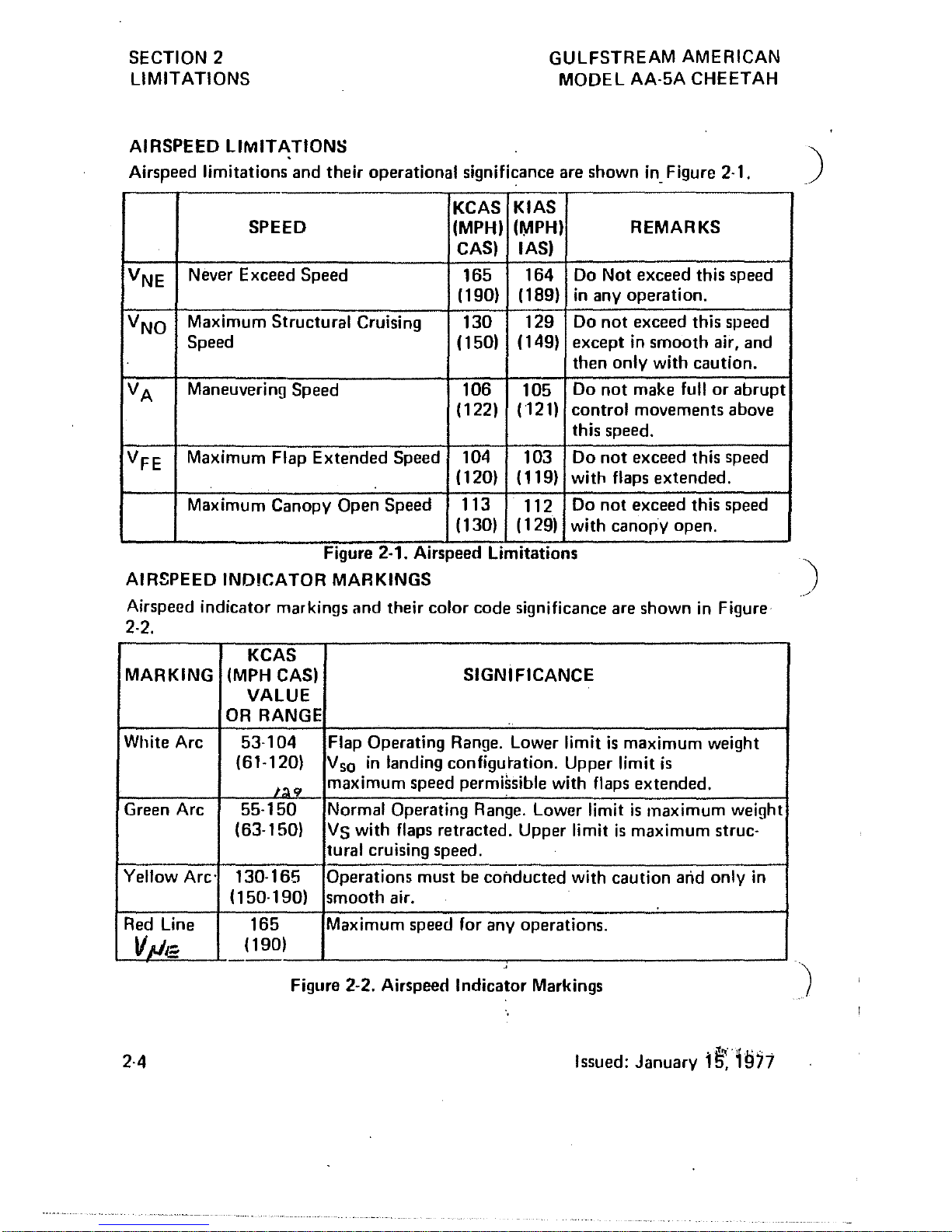
AIRSPEED
LIMITATIONS
Airspeed
limitations
and
their
operational
significance are
shown
in. Figure 2·1.
KCAS
KIAS
SPEED
(MPH)
(IYIPH)
REMARKS
CAS)
lAS)
V
NE
Never Exceed
Speed
165
164
Do
Not
exceed
this speed
(190) (189)
in
any
operation.
V
NO
Maximum
Structural
Cruising
130 129
Do
not
exceed this speed
Speed
(150)
(149)
except
in
smooth
air,
and
then
only
with
caution.
VA
Maneuvering
Speed
106
105
Do
not
make full
or
abrupt
(122)
(121)
control
movements
above
this speed.
V
FE
Maximum
Flap
Extended
Speed
104
103
Do
not
exceed this speed
(120)
( 119)
with
flaps
extended.
Maximum
Canopy
Open
Speed
113
112
Do
not
exceed this speed
(130) (129)
with
canorY
open.
Figure 2·1. Airspeed LimitatIOns
AIRSPEED
IND!CATOR
MARKINGS
Airspeed
indicator
markings
and
their
color
code
significance are
shown
in Figure
2·2.
KCAS
MARKING
(MPH CAS)
SIGNIFICANCE
VALUE
OR RANGE
White Arc
53·104
Flap Operating Range. Lower limit
is
maximum
weight
(61·120)
Vso
in
landing
configuration.
Upper limit
is
J:J.9
maximum
speed permissible with flaps
extended.
Green Arc
55·150
Normal Operating Range. Lower limit
is
maximum
weight
(63·150)
Vs
with flaps
retracted.
Upper limit
is
maximum
struc·
tural
cruising speed.
Yellow
Arc'
130·165
Operations
must be
conducted
with
caution
arid
only
in
(150·190)
smooth
air.
Red Line
165
Maximum speed for
any
operations.
V}le
(190)
Figure 2·2. Airspeed
Indicator
Markings
2·4
Issued:
January
1~~Hj71
)
)
L
GULFSTREAM AEROSPACE
MODEL AA-5A CHEETAH
POWER
PLANT LIMITATIONS
Engine Manulacturer: Avco Lycoming.
Engine Model
Num~er:
0-320-E2G
SECTION 2
LIMITATIONS
Engine Operating
Limits
lor
Takeoff and Continuous Operations:
Maximum Power: 150BHP
Maximum Engine Speed:
2700
RPM
Maximum
011
Temperature:
245
D
F
(118
D
C)
011
Pressure Minimum (Idling):
25
PSI
Maximum:
100
PSI
Normal Range: 60 to
JM)
PSI
Fuel Pressure, Minimum:
1).5
PSI
Maximum: 8
PSI
Propeller Manufacturer: McCauley
Propeller Model Number: 1 C1721 BTM
7359
Propeller Diameter, Maximum:
73
Inches.
POWER
PLANT
INSTRUM~NT
MARKINGS
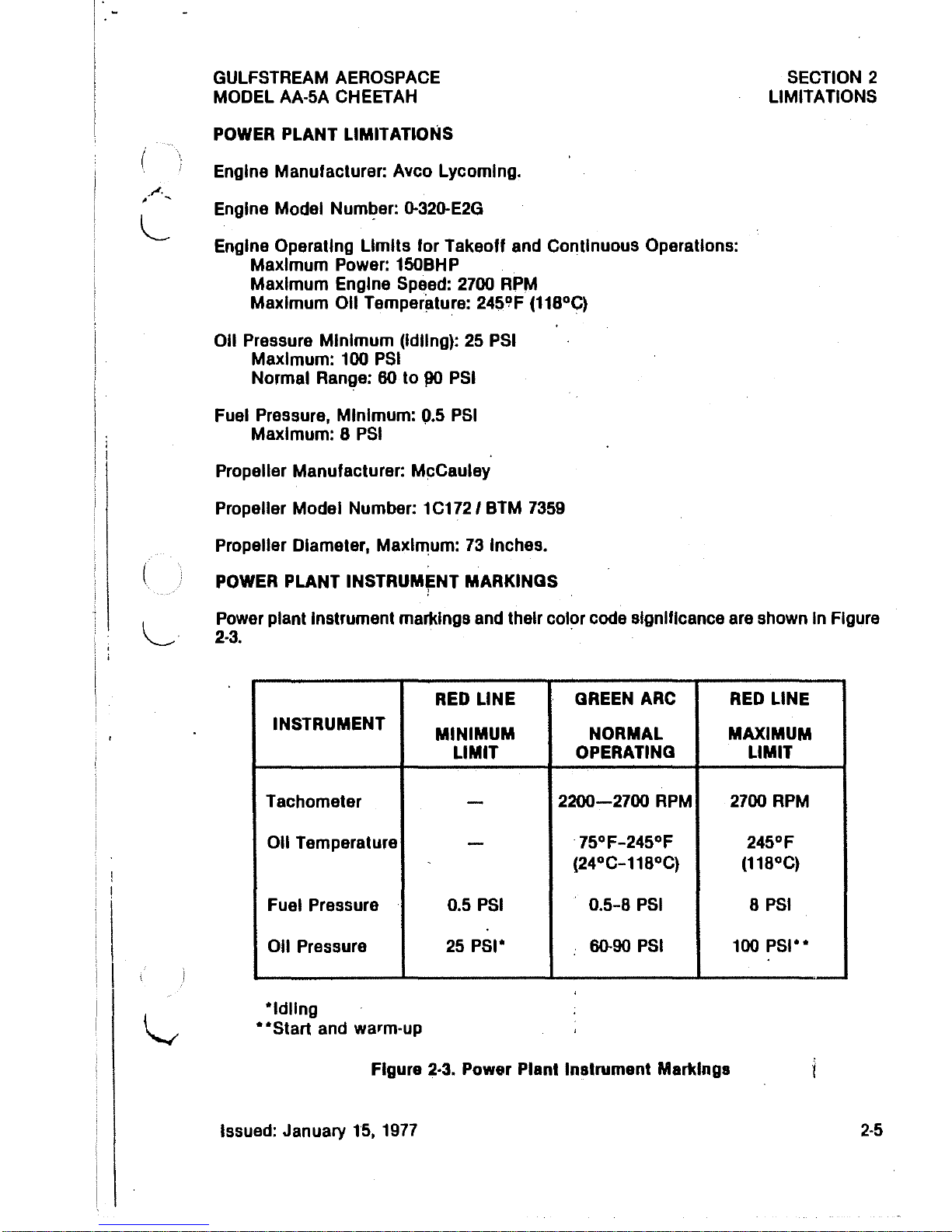
Power plant Instrument markings and their color code slgnillcance are shown In Figure
2-3.
.
RED
LINE
GREEN
ARC
RED
LINE
INSTRUMENT
MINIMUM
NORMAL
MAXIMUM
LIMIT
OPERATING LIMIT
Tachometer
-
2200-2700
RPM
2700
RPM
011
Temperature
-
75
D
F-245DF
245
D
F
(24DC-118
D
C)
(118
D
C)
Fuel Pressure 0.5
PSI
0.5-8
PSI
8
PSI
011
Pressure
25
PSI" 60-90
PSI
100
PSI""
"Idling
""Start
and warm-up
Figure 2·3. Power Plant Instrument Markings
Issued:
January
15,
1977
2-5
SECTION 2
LIMITATIONS
WEIGHT LIMITS
Nonnal Category
Maximum Takeoff Weight:
2200
Ibs.
Maximum Landing Weight:
2200
Ibs.
GULFSTREAM AEROSPACE
MODEL
AA·SA
CHEETAH
Weight
In
Baggage Compartment, Normal Category:
120
pounds maximum allowable
If
C.G.
Is within center of gravity envelope (Figure
6-S).
Refer to Section 6 for cargo
loading Instructions. .
Ullllty
Category
Maximum Takeoff Weight:
1850
Ibs.
Maximum Landing Weight:
18S0
Ibs.
Maximum Weight
In
Baggage Compartment:
In
the Utility Category, the baggage com·
partment and rear seat must not be occupied.
CENTER
OF GRAVITY LIMITS
Nonnal
Category
Center
of
Gravity Range:
Forward: 81.0 Inches aft
of
datum at
1780
Ibs.
or
less, with a straight line varia-
lion
to 85.6 Inches aft
of
datum .at
2200
Ibs.
Aft:
92.S
Inches aft
of
reference datum at all weights up
to
2200
Ibs.
a Reference Datum: Located
SO.O
Inches forward of the lower front face of the firewall.
Utility. Category
Center
of
Gravity Range:
Forward: 81.0 Inches aft of datum at
1780
Ibs.
or
lelJs,
with a straight line varia-
lion
to
81.8
Inches aft of datum at
1850
Ibs.
Aft: 86.0 Inches aft reference
of
datum at all weights up
to
1850 Ibs.
I Referellce Datum: Located
SO.O
Inches .forward
of
the lower front face
of
the firewall.
2·6
Revised: March
2,
1988

GULFSTREAM AMERICAN
MQPI=L AA·5A CHEETAH
MANEUVER
LIMITS
NORMAL
CATEGORY
SECTION 2
LIMITATIONS
This airplane
is
certificated
in
both
the
normal
and
utility category.
The
normal
category
is
applicable
to
airi:raft intended for non·aerobatic operations. These
include any maneuvers
incide"ntal
to
normal flying, stalls
(except
whip stalls)
and
turns
in which
the
angle
of
bank
is
not
more
than
60".
"
Maximum Design Weight" .
Design Maneuvering
SpeeJ1
.
.......
2200
Ibs .
•
106
KCAS (122 MPH)
The
AA·5A
is
approved for
the
following normal category maneuvers: Lazy
eights, chandelles, and steep
turns
in which
the
angle
of
bank
is
not
more
than
60".
UTILITY
CATEGORY
This airplane
is
not
designe~
for aerobatic flight. However,
in
the
acquisition
of
various certificates such
as
commercial pilot,
instrument
pilot and flight
instructor, certain maneuvers are required by
the
FAA. All
of
these maneuvers
except
spins, are
~ermitted
in this airJ;llane when
operated
in the Utility Category.
Maximum Design
Weight.
.
.......
1850
Ibs.
Design Maneuvering
Spe~d
............•.
106
KCAS (122 MPH)
In
the
Utility Category, the baggage
compartment
and rear seat
must
not
be
occupied. No aerobatic
manel.Jvers are approved
except
those listed below:
Maneuver
Chandelles
Lazy
Eigh~s
•.
Steep Tlirns
Stalls (Ex"cept
Whip Stalls)
Spins
Prohibited
Recommended
Entry
Speed-
.106
KCAS
(122
MPH)
.106
KCAS
(122
MPH)
.
106
KCAS
(122
MPH)
• Slow Deceleration
•
Abrupt
use
of
the controls
i~
prohibited above
106
KCAS
(122
MPH).
Issued:
January
15.1977
2·7
SECTION 2
LIMIT ATIONS
GULFSTREAM
AMERICAN
MODEL
AA·5A
CHEETAH
The
important
thing
to
remember
in
flight maneuvers
is
that
the
airplane
is
clean
in
aerodynamic
design
and
will build
up
speed
quickly
with
the
nose
down.
Since )
proper
speed
control
is
essential for
execution
of
any
maneuver,
care
should
.
always
be exercised
to
avoid excessive -lJeed
and
its
resultant
heavy airframe
loads.
In
the
execution
of
all maneuvers, avoid
abrupt
use
of
controls.
As
noted,
SPINS ARE
PROHIBITED.
In case
of
fin
inadvertent
spin, recovery
is
effected
by
reducing
throttle
to
idle, neutralizing:the aileron, applying full
rudder
opposite
to
the
spin
rotation,
and
applying full
down
elevator
simultaneously
with
rudder
application.
The
controls
should be. applied briskly
and
held until
rotation
stops.
As
the
rotation
stops, neutralize
the
anti· spin
rudder,
then
apply
s~ooth
elevator
back pressure
to
bring
the
nose up
to
level flight.
FLIGHT
LOAD FACTOR LIMITS
NORMAL
CATEGORY
Flight Load
Factors
(Gross Weight -
2200
Ibs.)
Flaps
Up
.....
Flaps Down
UTILITY
CATEGORY
Flight Load Factors (Gross Weight -
1850Ibs.)
Flaps Up
..
Flaps Down
FUEL
LIMITATIONS
Standard
Tanks
+3.8g,
-1.52g
.
....
+3.5g
+4.4g,
-1.76g
.....
+3.5g
2
Tanks:
19
U.S. Gallons each (15.8 Imperial Gallons)
(71.9
Liters)
Total
Fuel:
38
U.S. Gallons (31.6 Imperial Gallons)
(143.8
Liters)
Usable Fuel (all flight
conditions):
37 U.S. Gallons
(30.8
Imperial Gallons)
(140
Liters)
Unusable Fuel:
1.0
U.S. Gallon (.8 Imperial Gallon)
(3.79
Liters)
Optional
Long Range
Tanks
2
Tanks:
26.3
U.S. Gallons (21.9 Imperial Gallons) (99.5 Liters)
Total
Fuel:
52.6
U.S. Gallo.ns (43.8 Imperial Gallons) (199.1 Liters)
)
Usable Fuel (all flight
conditions):
51
U.S. Gallons
(42.5
Imperial Gallons) .
')
(193
Liters) .
Unusable Fuel:
1.6 U.S. Gallons (1.3 Imperial Gallons) (6.1 Liters)
Issued:
January
15,
,1977,
.
2·8
GULFSTREAM AMERICAN
"'i;,~~~ODEL
AA-5A CHEETAH
PLACARDS
SECTI,QN
2
LIMITATIONS
The following information
is
displayed
in
the form
of
composite
or
individual
placards:
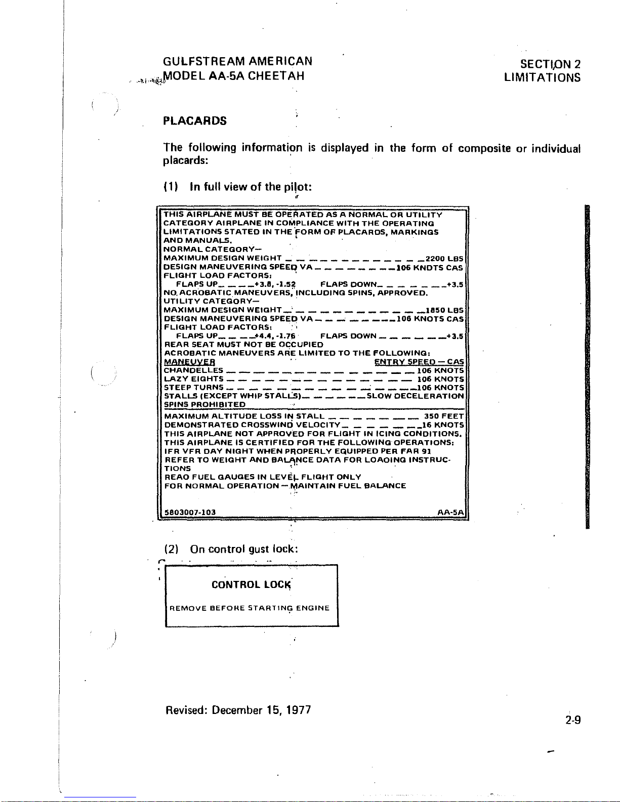
(11
I n full view
of
the pilot:
THIS
AIRPLANE
MUST
BE
OPERATED
AS A NORMAL
OR
UTILITY
CATEGORY
AIRPLANE
IN
COMPLIANCE
WITH
THE
OPERATING
LIMITATIONS
STATED
IN
THE
'FORM
OF
PLACARDS,
MARKINGS
AND
MANUALS.
' .
NORMAL
CATEGORY-
.
MAXIMUM
DESIGN
WEIGHT
_____________
2200
LBS
DESIGN
MANEUVERING
SPEEQ
VA
________
106
KNOTS
CAS
FLIGHT
LOAD
FACTORS.
'
FLAPS
UP
____
+3.8,
-1.5~
FLAPS
DOWN
_______
+3.5
NO.
ACROBATIC
MANEUVERS,
INCLUDING
SPINS,
APPROVED.
UTILITY
CATEGORY-
.
MAXIMUM
DESIGN
WEIGHT
_'
___________
1850
LBS
DESIGN
MANEUVERING
SPEED
VA
__
-'
_____
106
KNOTS
CAS
FLIGHT
LOAD
FACTORS.
. ;
FLAPS
UP
____
+4.4,
-1.76
FLAPS
DOWN
______
+3.5
REAR
SEAT
MUST
NOT
BE
OCCUPIED
ACROBATIC
MANEUVERS
ARE
LIMITED
TO
THE
FOLLOWING,
MANEUyER
ENTRY
SPEED -CAS
CHANDELLES
______________
106
KNOTS
LAZY
EIGHTS
______________
106
KNOTS
STEEP
TURNS
__________
-.:
____
106
KNOTS
STALLS
(EXCEPT
WHIP
STALLsI
______
SLOW
DECELERATION
SPINS
PROHIBITED
MAXIMUM
ALTITUDE
LOSS
IN
STALL
_______
350
FEET
DEMONSTRATED
CROSSWIND
VELOCITY
_______
16
KNOTS
THIS
AIRPLANE
NOT
APPROVED
FOR
FLIGHT
IN
ICING
CONDITIONS.
THIS
AIRPLANE
IS
CERTIFIED
FOR
THE
FOLLOWING'
OPERATIONS,
IFR
VFR
DAY
NIGHT
WHEN
PROPERLY
EQUIPPED
PER
FAR
91
:I~';SR
TO
WEIGHT
AND
BA~!'ICE
DATA
FOR
LOAOING
INSTRUC-
REAO
FUEL
GAUGES
IN
LEVEl-
FLIGHT
ONLY
FOR
NORMAL
OPERATION
-.II1AINTAIN
FUEL
BALANCE
5803007-103
(2) On control gust lock:
~~~~----~~~~~--~----~
CONTROL
lOC~
REMOVE
BEFOHE
STAR
TIN,?
ENGINE
Revised: December 15, 1977
AA-5A
2-9
SECTION 2
LI
MIT
A TIONS
GULFSTREAM AMERICAN
MODEL
AA-5A CHEETAH
(31
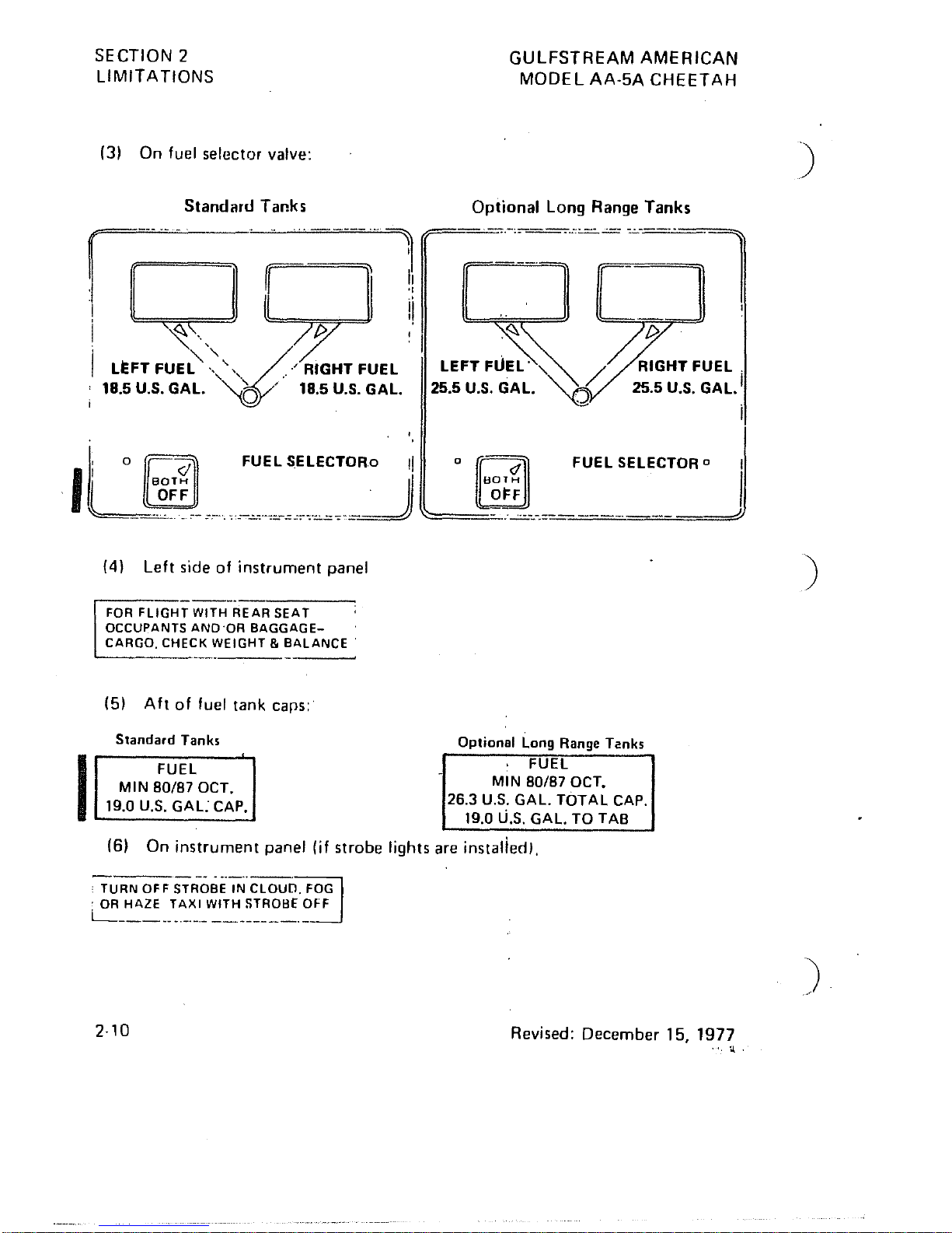
On fuel selector valve:
Standard
Tanks
Optional Long Range Tanks
fI-
n
rllr
D~[~~l
I
~
..
~'IGJ
I LEFT FUEa:-
'>""
/'
RIGHT
FUel
LE~~
:~~
/
I 18.5 U.S.
GAl.
,,©/' 18.5 U.S.
GAl.
25.5
U.S.
GAl.
(4)
Left side of instrument panel
FOR
FLIGHT
WITH
REAR
SEAT
OCCUPANTS
AND'OR
BAGGAGE-
CARGO.
CHECK
WEIGHT & BALANCE'
(5)
A
It
of fuel tank caps:
Standard
Tank,
I
FUEL
MIN
80/87
OCT.
19.0 U.S.
GAL
CAP.
Optional Long Range Tanks
FUEL
MIN
80/87
OCT.
26.3
U.S.
GAL.
TOTAL
CAP.
19.0
U.S.
GAL.
TO TAB
(6)
On instrument panel (if strobe lights are instalied).
-----
...
-
..
-~
,
TURN
OFF
STROBE
IN
CLOUD.
FOG
. OR
HAZE
TAXI
WITH
STROBE
OFF
~------."."."
--""---_._-
2·10
Revised: December
15,1977
".
"J..
)
)
)
 Loading...