

Page 1

OPERATING MANUAL
FLIGHT CONTROLS
2A-27-10: General
The Gulfstream IV primary flight controls system, shown in Figure 1, is a mechanically
actuated, hydraulically operated system that provides boosted surface control to
overcome the aerodynamic forces associated with high speed flight. This allows the
aircraft to be comfortably and reliably steered through the pitch, roll and yaw axes.
The primary flight control surfaces (elevators, ailerons and rudder) are positioned by
tandem type hydraulic actuators. The actuators receive hydraulic operating pressure
from both the Combined and Flight hydraulic systems, as shown in Figure 2. Both
hydraulic systems maintain a system pressure of 3000 psi. Loss of a single hydraulic
system has no effect on operation of the primary flight controls, as the remaining system
is capable of maintaining actuator load capacity. In the event of total loss of hydraulic
pressure in bothhydraulic systems, the primary flight controls revert to manual operation.
Mechanical pitch, roll and yaw trim systems allow the flight crew to trim the aircraft. The
pitch trim system can also be controlled electrically by pitch trim switches on the control
wheels.
A gust lock secures the elevators, ailerons and rudder to prevent wind gust damage to
the surfaces.
Secondary flight controls, shown in Figure 1, include flaps, ground spoilers and
speedbrakes. These flight controls are hydraulically powered and electrically or
mechanically controlled. The mechanically operated horizontal stabilizer moves in
conjunction with the flaps to maintain longitudinal trim.
AnAngle-of-Attack (AOA) system provides outputs to the control column shakers, control
column pusher, approach indexers, normalized AOA display and stall barrier system. The
control column shakers provides early warning of a stall scenario by vibrating the control
column before the stall while the control column pusher automatically initiates lowering
the nose if the stall is imminent.
The Gulfstream IV uses an aircraft configuration warning system to monitor landing gear,
flap, speed brake and power lever position. If an unsafe configuration is detected, the
system provides a visual and / or aural warning.
On CAA certified aircraft, a flight control automatic failure detection system compares
control inputs to actuator outputs. If a malfunction is detected, the system shuts off power
to the affected actuator.
The flight controls system is divided into the following subsystems:
• 2A-27-20: Pitch Flight Control System
• 2A-27-30: Yaw Flight Control System
• 2A-27-40: Roll Flight Control System
• 2A-27-50: Horizontal Stabilizer System
• 2A-27-60: Flaps System
• 2A-27-70: Spoiler System
• 2A-27-80: Gust Lock System
PRODUCTION AIRCRAFT SYSTEMS 2A-27-00
Page 1
January 31/02
Revision 6
Page 2

OPERATING MANUAL
THIS PAGE IS INTENTIONALLY LEFT BLANK.
Page 2
January 31/02
PRODUCTION AIRCRAFT SYSTEMS2A-27-00
Page 3
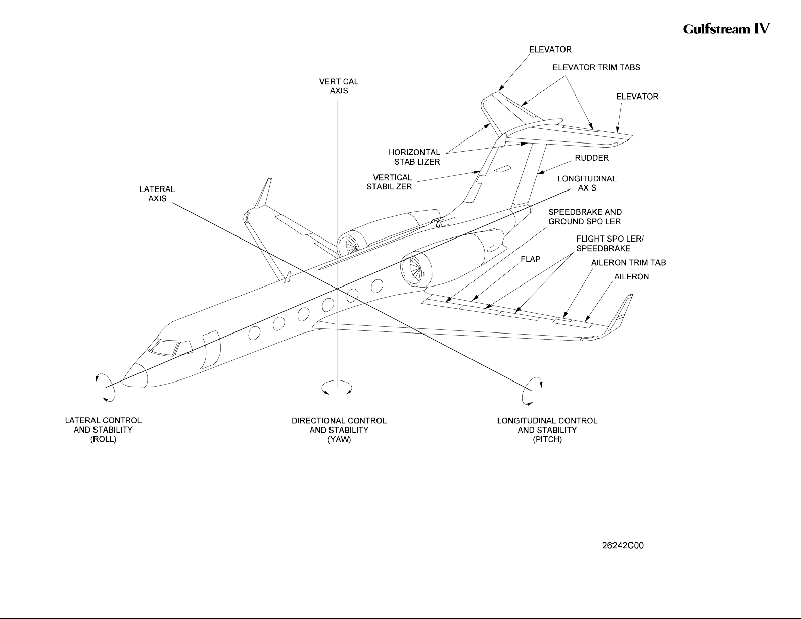
OPERATING MANUAL
GIV Flight Controls /
Aerodynamic Axes
Figure 1
2A-27-00
Page 3 / 4
January 31/02
Page 4
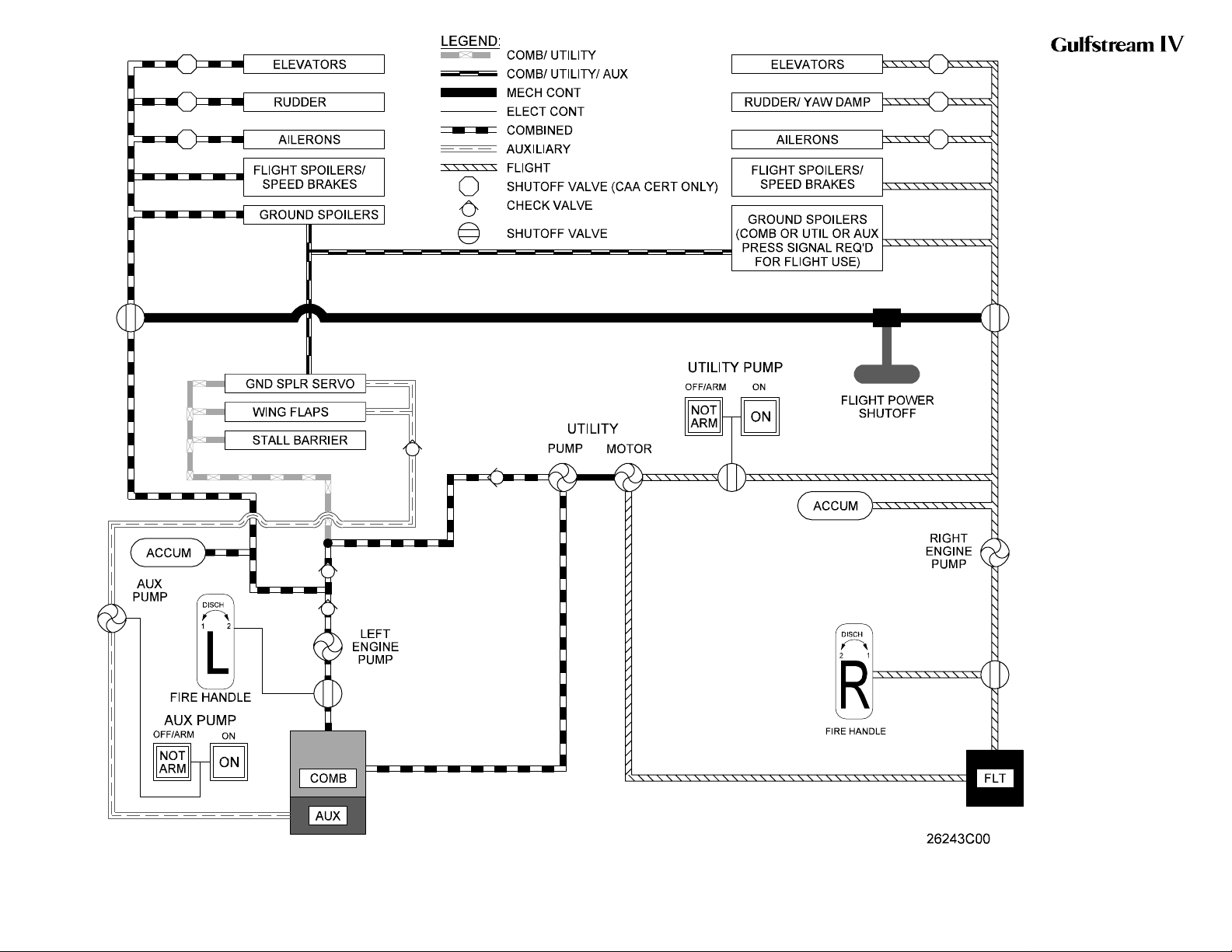
OPERATING MANUAL
GIV Flight Controls Fluid
Power Diagram
Figure 2
2A-27-00
Page 5 / 6
January 31/02
Page 5

OPERATING MANUAL
2A-27-20: Pitch Flight Control System
1. General Description:
Aircraft movement about the lateral axis (pitch) is controlled by the position of the
elevators. The elevators are manually controlled, mechanically actuated and
hydraulically boosted airfoils mounted on the trailing edge of the horizontal
stabilizer.Total elevator travel ranges from 24° trailing edge up to 13° trailing edge
down.
The elevators are positioned by a tandem type hydraulic actuator. The actuator
receives hydraulic operating pressure simultaneously from both the Combined
and Flight hydraulic systems during normal operations. Loss of a single hydraulic
system has no effect on operation of the elevators, as the remaining system is
capable of maintaining actuator load capacity. In the event of total loss of
hydraulic pressure in both systems, the elevators revert to manual operation.
Manual reversion is also possible through use of a flight power shutoff valve and
its pedestal-mounted control handle.
A pitch trim system is used to position a trim tab attached to the trailing edge of
each elevator. The tabs are positioned either manually by a pedestal-mounted
control wheel or electrically by pitch trim switches on the control wheels.
An Angle-of-Attack (AOA) system provides outputs to the control column shakers,
control column pusher, approach indexers, normalized AOA display and stall
barrier system. The control column shakers provides early warning of a stall
scenario by vibrating the control column before the stall while the control column
pusher automatically initiates lowering the nose if the stall is imminent.
On CAA certified aircraft,aflight control automatic failure detection system
compares control column inputs to elevator actuator outputs. If a malfunction is
detected, the system shuts off either or both hydraulic power sources to the
affected actuator.
The pitch flight control system consists of the following subsystems, units and
components:
• Control column system
• Mechanical actuation system
• Hydraulic boost system
• Manual reversion system
• Pitch trim system
• Angle-of-attack / stall barrier system
• Failure detection system (CAA aircraft only)
2. Description of Subsystems, Units and Components:
A. Control Column System:
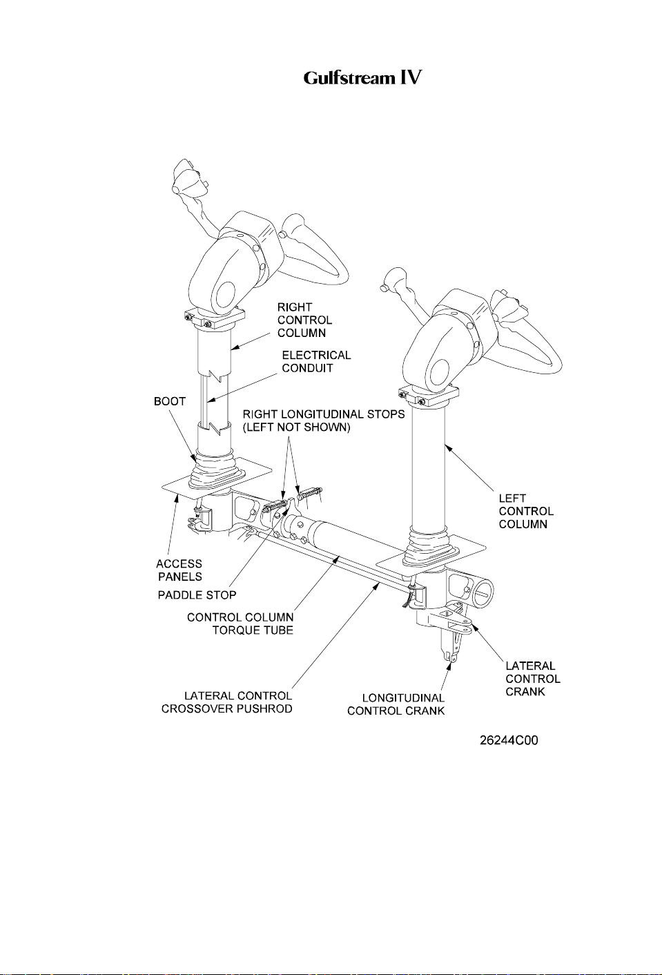
(See Figure 7.)
The pilot’s and copilot’s control columns mount to a common transverse
torque tube supported by a bearing on each end. Moving the control
column fore and aft rotates the torque tube that, in turn, transmits the
inputs rearward through conventional mechanical linkage. Adjustable stops
on the torque tube limit control column movement to eight inches aft and
five inches forward of the neutral position.
An eddy current damper is connected to the bottom of the control column
PRODUCTION AIRCRAFT SYSTEMS 2A-27-00
Page 7
January 31/02
Revision 6
Page 6

OPERATING MANUAL
output crank. The damper is designed to sense control column movement
and provide a counteracting damping force or artificial feel. Damping force
is generated in proportion to control column velocity. Should the eddy
current damper jam or fail, its internal clutch releases to allow control
column movement.
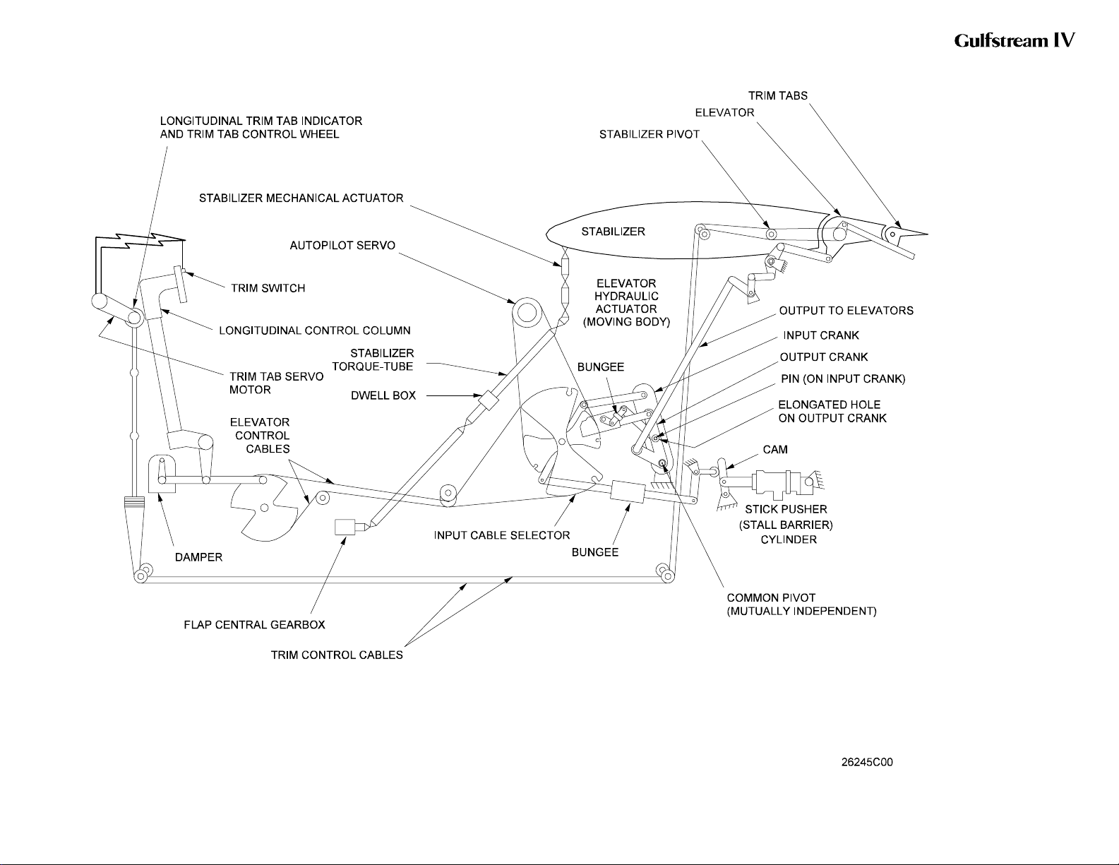
B. Mechanical Actuation System:
(See Figure 3.)
Control column inputs are transmitted rearward through a system of push-
pull rods, bellcranks, cables and a sector assembly to an input cable sector
below the base of the vertical stabilizer in the tail compartment. Connected
to the input cable sector are the elevator actuator, autopilot servo and
stability springs. Final output of the sector is to the elevator actuator input
lever.
Movement of the actuator input lever displaces the elevator actuator’s
servo control valve, directing Combined and Flight hydraulic system
pressure to the actuator cylinders. When under pressure, the actuator body
moves while the its piston remains motionless. Movement of the actuator
body in turn moves its output crank. Output crank movement is transmitted
upward and aft to the left and right elevators through a system of push-pull
rods and cranks, resulting in the desired elevator deflection.
Stability springs, commonly referred to as down springs, provide
approximately 13 pounds of pull on the control columns. This pulling force
keeps pilot feel forces out of the friction band at low airspeeds.
C. Hydraulic Boost System:
The elevator actuator is a dual tandem actuator consisting of two pistons
secured to a common shaft. The pistons move inside a common cylinder
divided to create two separate cylinders. One cylinder receives Flight
hydraulic system pressure while the other cylinder receives Combined
hydraulic system pressure.
Mechanical movement of the actuator input lever moves the servo control
valve from its neutral position. The servo control valve then directs
hydraulic pressure to one of the actuator’s two cylinders and connects
each cylinder’s opposite side to return. When the elevator reaches the
desired deflection, the servo control valve shifts to its neutral position to
lock hydraulic pressure within the actuator, in effect preventing further
surface movement.
The elevator actuator also has an internal hydraulic damper that provides
damping force proportional to the square of its input velocity. This damping
action ensures operational stability for the elevators when hydraulically
boosted whereby a portion of the actuator’s output is fed back to the input
system.
D. Manual Reversion System:
During normal flight operations, the Combined and Flight hydraulic
systems each supply and maintain 3000 psi to the elevator actuator. Loss
of system pressure due to a single system failure has no effect on
operation of the pitch flight control system.
Loss of system pressure from both hydraulic systems will automatically
revert the pitch flight control system to manual control. As pressure at the
Page 8
January 31/02
PRODUCTION AIRCRAFT SYSTEMS2A-27-00
Revision 6
Page 7

OPERATING MANUAL
actuator drops below 60 psi, bypass valves within the actuator open to
allow the actuator piston to idle. With the actuator piston idling, the system
is said to be in manual reversion, technically explained in the following
paragraph.
The actuator input crank and output crank rotate on a common pivot point.
They are linked by a pin and elongated slot arrangement. The input crank
is on the pin and the output crank is on the slot. With the actuator piston
idling, the pin moves within the slot until it reaches either end. At this point,
mechanical contact is made and the input crank now drives the output
crank. The output crank in turn drives the left and right elevators through its
push-pull rods and cranks.
Manual reversion of the pitch flight control system is also possible by
closing a normally open flight power shutoff valve. The flight power shutoff
valve is a mechanically operated shutoff valve located between the
Combined and Flight hydraulic system pressure sources and the elevator
actuator (as well as the aileron, rudder and flight / ground spoiler actuator)
pressure lines. The valve consists of two mechanically connected but
hydraulically isolated sections. A controlex cable connects the valve to a
FLIGHT POWER SHUT OFF handle located on the left aft side of the
cockpit center pedestal. See Figure 8.
Moving the FLIGHT POWER SHUT OFF handle up from its stowed
(horizontal) position to the vertical position mechanically closes the flight
power shutoff valve. With the valve closed, operating pressure is removed
from the actuator, allowing the piston to idle.
The resultant advantage of the flight power shutoff provision is the ability to
bypass a malfunctioning actuator (such as would be the need in the
unlikely event of an actuator jam) and manually fly the aircraft. Although
control column effort and response time to inputs are increased while in
manual reversion, the aircraft remains capable of positive and harmonious
control.
E. Pitch Trim System:
(See Figure 5 and Figure 9.)
(1) Elevator Trim Tabs:
A trim tab is installed on the trailing edge of each elevator. The tabs
are mechanically positioned through cable-driven drum actuators
located in each elevator. The trim actuators can be operated
manually or electrically as described in the following paragraphs.
Elevator trim tab travel ranges from 22 ±1° tab trailing edge down
(aircraft nose up) to 8 ±1° tab trailing edge up (aircraft nose down).
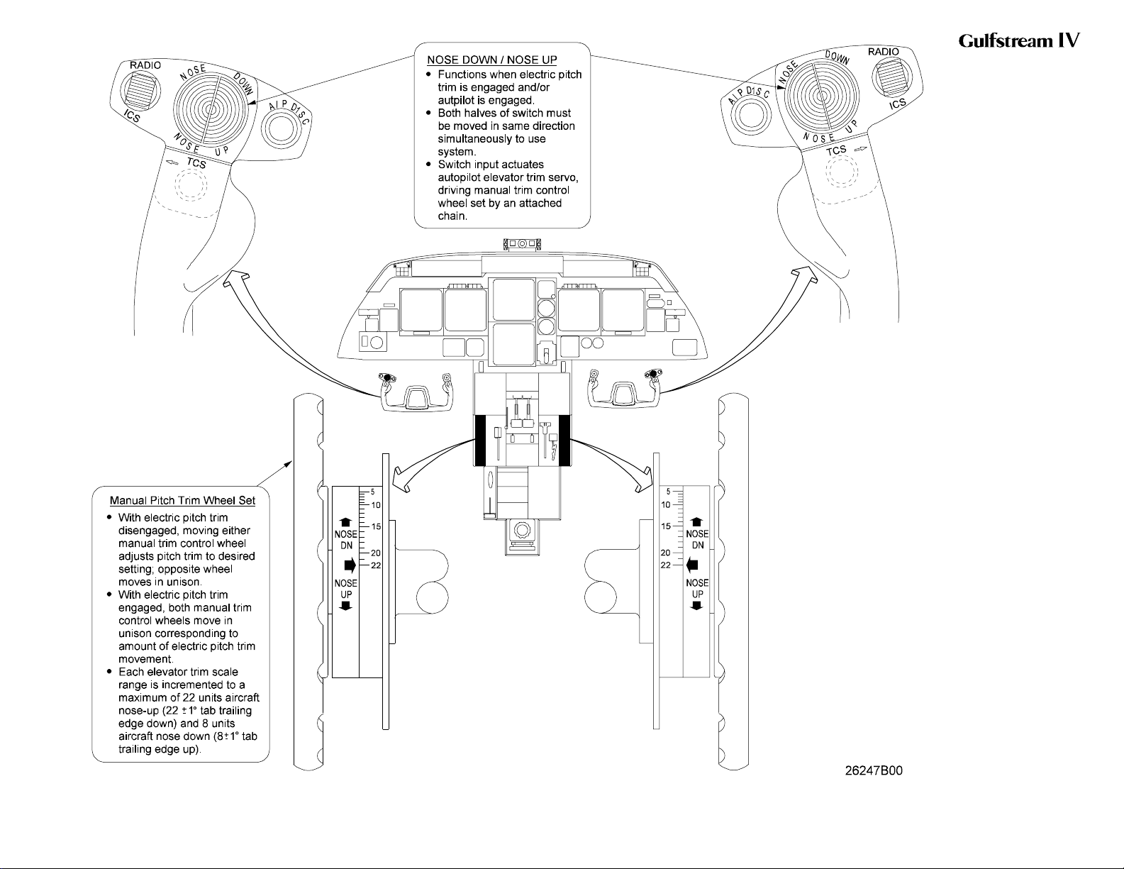
(2) Manual Trim Control:
Manual control of pitch trim is accomplished by an interconnected
manual trim control wheel set. A trim control wheel and elevator trim
scale are provided on each side of the cockpit center pedestal. With
electric pitch trim disengaged, moving either manual trim control
wheel adjusts pitch trim to the desired setting; the opposite wheel
moves in unison. With electric pitch trim engaged, both manual trim
control wheels move in unison corresponding to the amount of
electric pitch trim movement. Each elevator trim scale range is
incremented to a maximum of 22 units aircraft nose-up (22 ±1° tab
PRODUCTION AIRCRAFT SYSTEMS 2A-27-00
Page 9
January 31/02
Revision 6
Page 8
OPERATING MANUAL
trailing edge down) and 8 units aircraft nose-down (8 ±1° tab trailing
edge up).
Mechanical stops limit elevator trim wheel movement to 6.6 turns
from each stop. A shear rivet installed in the cockpit portion of the
system prevents application of excessive force by shearing at
approximately 31 pounds of force.
(3) Electric Pitch Trim:
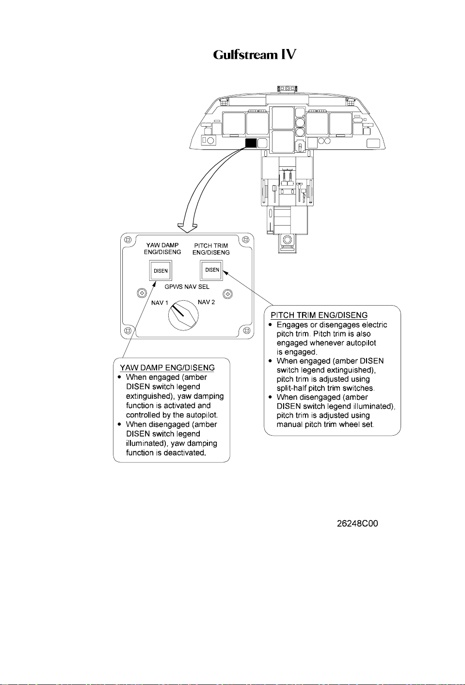
Located on the pilot’s flight panel, the PITCH TRIM ENG / DISENG
switch engages or disengages the electric pitch trim. Pitch trim is
also engaged whenever the autopilot is engaged. With electric pitch
trim engaged (amber DISEN switch legend extinguished), pitch trim
can be adjusted through use of a split-half pitch trim switch
(sometimes referred to as a “beep” switch) installed on the outboard
grip of each control wheel. Switch positions are labeled NOSE
DOWN and NOSE UP. Inadvertent actuation of pitch trim, including
runaway, is minimized through the split-half switch design. In order
for the pitch trim to be actuated, both halves of the switch must be
simultaneously moved in the same direction.
Movement of the electric pitch trim switch to NOSE DOWN or NOSE
UP actuates the autopilot elevator trim servo. The trim servo is
connected to the manual trim control wheel set by a chain. The
chain-driven movement of the manual trim control wheel set in turn
positions the elevator trim tabs.
The electric pitch trim is normally checked by the flight crew on the
first flight of the day, during the Before Starting Engines checklist. A
check usually consists of running the elevator trim fully up, then fully
down, using normal methods, i.e., using both halves of the switch
simultaneously. This is followed by attempting to run the pitch trim
using each half of the switch alone. Any movement resulting from
using either half of the switch alone indicates a malfunction that
should be corrected before flight. The check is concluded by setting
pitch trim for the takeoff Center of Gravity (CG) condition as
determined using the Airplane Flight Manual.
(4) Elevator Trim TabActuator Heat System:
Electrically-heated elevator trim tab actuators are incorporated on
airplanes SN 1380 and subsequent and SN 1000 through 1379
havingASC 342. These actuators are designed to alleviate frozen or
stiff trim tab actuators possible in extreme cold temperatures. The
system receives power from Phase C of the Left Main AC bus.
Operation of the system is automatic and transparent to the flight
crew.
F. Angle-of-Attack / Stall Barrier System:
(See Figure 4, Figure 10 and Figure 11.)
While in flight, the Angle-of-Attack (AOA) system monitors aircraft AOA to
provide warnings of an approaching stall. If AOA continues to increase
toward aerodynamic stall, the system applies a nose down control input
through the stall barrier system.
The AOA / stall barrier system consists of the following units and
components:
Page 10
January 31/02
PRODUCTION AIRCRAFT SYSTEMS2A-27-00
Revision 6
Page 9

OPERATING MANUAL
• AOA probes
• AOA display and approach indexer
• Stall warning computers
• Pilot and copilot control column shaker motors
• Stall barrier system
AOA becomes fully functional as the aircraft becomes airborne, i.e., when
the nutcracker shifts to theAIR mode. The control column shaker, however,
is disabled for the first five seconds following rotation to eliminate nuisance
activity. Pulling the SHAKER #1 and / or SHAKER #2 circuit breakers, as
appropriate, is the only way to disable a control column shaker in flight;
however, such action completely disables the associated stall warning
computer(s). System design is such that either stall warning computer is
capable of operating the control column shaker and control column pusher
should the other computer become disabled.
(1) AOA Probes:
AnAOA probe / transducer assembly is installed on the left and right
forward fuselage. The cone-shaped probes freely rotate in the
airstream to provide AOA reference data for the stall warning / stall
barrier systems and AOA display data for the flight crew. The left
AOA probe provides data the No. 1 stall warning computer while the
right AOA probe provides data the No. 2 stall warning computer.
Heating elements prevent ice accumulation on the probe and
condensation within the transducer case.
(2) AOA Display and Approach Indexer:
AOA display data supplied by the probes includes the normalized
AOA display and the approach indexer. Normalized AOA display is
shown on the lower left portion of the Primary Flight Display (PFD)
and consists of a vertical scale marked from 0.2 to 1.1 in 0.1
increments. At the bottom of the scale is a three-digit display
surrounded by a pointer that provides AOA indication within a 0.01
resolution. As AOA changes, the display / pointer moves up and
down to correspond with the indication on the scale.
An AOA approach indexer on either side of the windshield center
post indicates the optimum AOA for approach and landing. The No.
1 AOA system drives the pilot’s indexer while the No. 2 AOA system
drives the copilot’s indexer. During approach and landing, the AOA
system illuminates each indexer’s red chevron if AOA is too high, a
green circle if AOA is correct or an amber chevron if AOA is too low.
(3) Stall Warning Computers:
The No. 1 and No. 2 stall warning computers receive the following
inputs and then provide outputs to the control column shaker motors
and stall barrier system:
• AOA reference data from the associated probes
• Altitude data from the DADCs
• Nutcracker mode from the nutcracker relays
• Flaps position from the 39°flap relay
(4) Control Column Shaker Motors:
PRODUCTION AIRCRAFT SYSTEMS 2A-27-00
Page 11
January 31/02
Revision 6
Page 10

OPERATING MANUAL
A control column shaker motor is attached to the pilot and copilot
control columns. When activated by a stall warning computer, the
motor drives an off-center weight that vibrates the control column.
Activation of one motor affects both control columns due to their
mechanical interconnection.
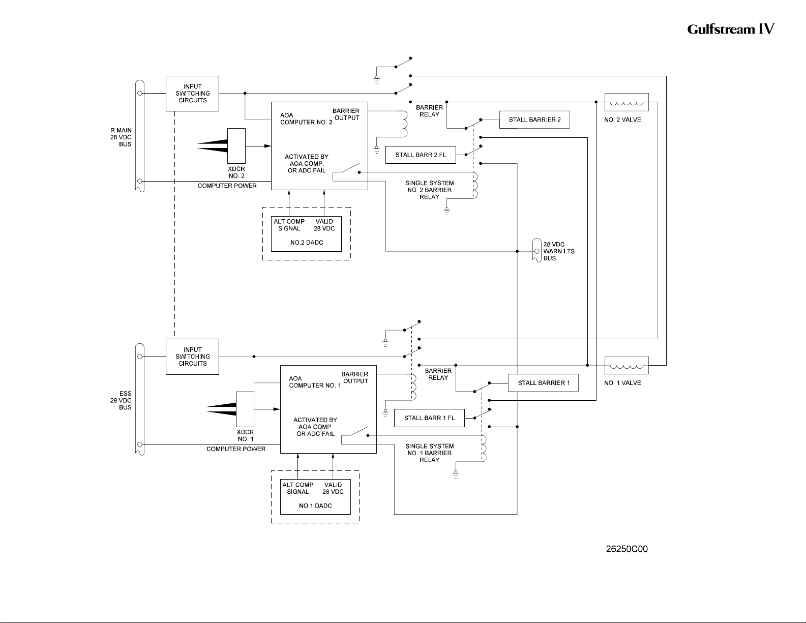
(5) Stall Barrier System:
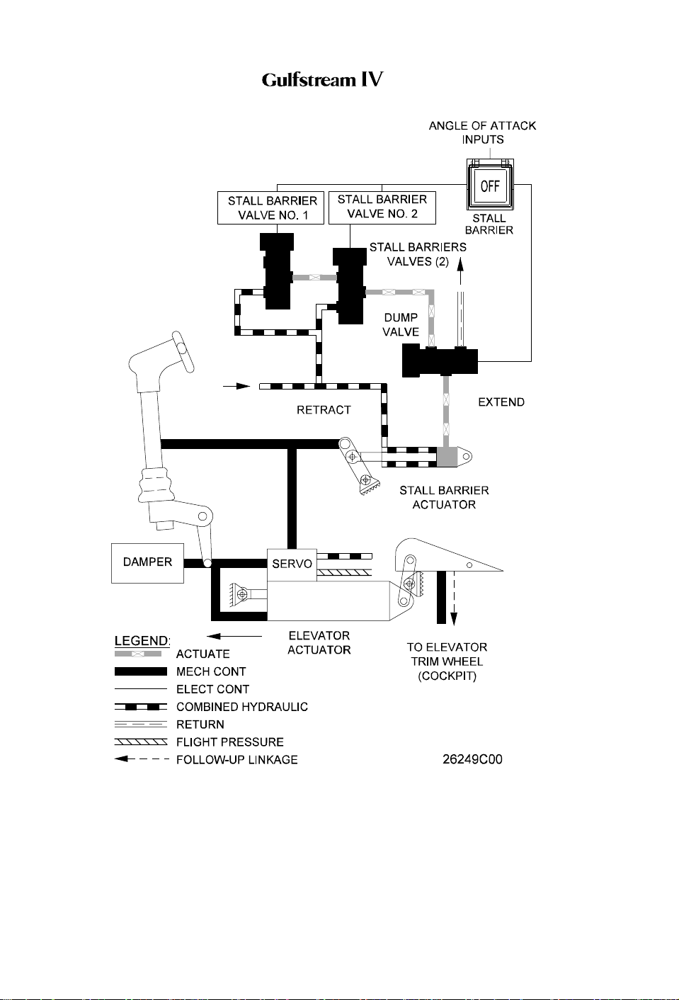
A stall barrier system (control column pusher) is incorporated in the
pitch flight control system to prevent a stall by forcing the control
columns forward when the flight crew fails to respond to either visual
indications or to the control column vibrations that warn of
impending stall. The system consists of two normally closed stall
barrier valves and an actuating cylinder that is mechanically linked
to the elevator actuator input sector. One valve receives signals
from the No. 1 stall warning computer while the other valve receives
signals from the No. 2 stall warning computer. If one system fails,
the remaining system is capable of operating the system.
When a high AOA is reached, the control column shaker motors are
activated. When a more severe AOA is reached, the control column
pusher trip detector activates its respective stall barrier valve. The
activation signal will originate from whichever system is operating No. 1, No. 2 or both. When a stall barrier valve is activated,
Combined (or Utility) hydraulic system pressure is ported to the
extend side of the stall barrier actuating cylinder. As the cylinder
extends, it applies an input to the elevator actuator input sector.This
input causes the elevator actuator to drive the elevator trailing edges
down; the control column drives forward accordingly, to
approximately one inch forward of neutral. When AOA has
decreased more than one degree, the stall barrier system
disengages.
The force generated by the stall barrier system is sufficient to
overcome any autopilot force, however, the system can be manually
overcome by the flight crew.
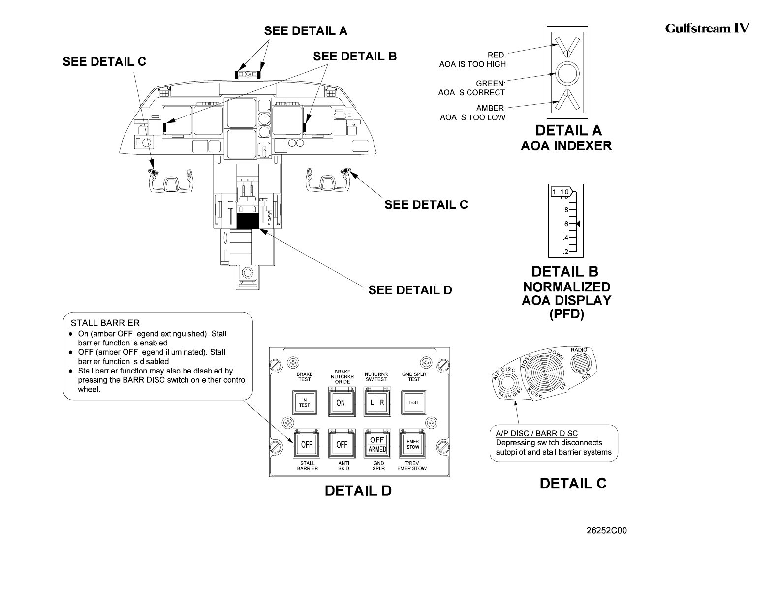
The stall barrier system can be deactivated by pressing the BARR
DISC button on either control wheel. The BARR DISC button also
serves as the autopilot disconnect button, thus is also labeled A/P
DISC accordingly. Deactivation of the stall barrier system is also
possible through selection of the STALL BARRIER switchlight to
OFF. The switchlight is located on the cockpit center pedestal just
below the left HP fuel cock. An amber OFF legend in the switchlight
will illuminate when the system is deactivated and will extinguish
when activated.
(6) Stall Warning / Stall Barrier System Test:
The stall warning / stall barrier system is normally tested by the flight
crew on the first flight of the day or every eight hours of flight time.
The test is performed only on the ground and cannot be tested in
flight. It consists of the following steps:
(a) Select the STALL BARRIER switch to on. Verify amber OFF
legend is extinguished.
(b) On both the pilot’s and copilot’s display controllers, depress
the TEST function key.
Page 12
January 31/02
PRODUCTION AIRCRAFT SYSTEMS2A-27-00
Revision 6
Page 11

OPERATING MANUAL
(c) On both the pilot’s and copilot’s display controllers,
simultaneously depress and hold the Sea Level (S/L) line
select key.
(d) Continue holding both S/L line select keys until the
normalized AOA indicator pointer slews to full scale and
observe the following:
• Stall warning (control column shaker) occurs between
0.70 and 0.80
• Stall barrier (control column pusher) occurs between
0.95 and 1.07
• Check that the BARR DISC button will override the
pusher
(e) On both the pilot’s and copilot’s display controllers,
simultaneously depress and hold the ALT line select key.
(f) Continue holding both ALT line select keys until the
normalized AOA indicator pointer slews to full scale and
observe the following:
• Stall warning (control column shaker) occurs between
0.54 and 0.65
• Stall barrier (control column pusher) occurs between
0.79 and 0.90
• Check that the BARR DISC button will override the
pusher
NOTE:
Both pilot’s and copilot’s sides have to be tested
simultaneously in order to activate the control column
pusher.
NOTE:
Another momentary push of the TEST function key
may be required to ensure the AOA indicator is in the
normal area prior to takeoff.
G. Failure Detection System:
CAA Certified Aircraft Only: A flight control automatic failure detection
system monitors flight control inputs from the control columns and
compares them to the elevator actuator outputs. If the system detects a
failure, it automatically shuts off hydraulic pressure to the actuator and
triggers the appropriate warning on the Crew Alerting System (CAS). Once
activated by a malfunction, hydraulic pressure is inhibited until power to the
respective monitoring system is interrupted, for instance, by pulling and
resetting the appropriate circuit breaker.
The monitoring system is a dual-channel system. One channel controls the
Combined hydraulic system pressure source while the other controls the
Flight hydraulic system pressure source. Power for the system is received
from the 28 VDC Essential DC bus.
A pair of limit switches monitor applied control column input while a pair of
PRODUCTION AIRCRAFT SYSTEMS 2A-27-00
Page 13
January 31/02
Revision 6
Page 12
OPERATING MANUAL
reed switches monitor actuator output in response to the input.
If a disagreement occurs between control column input and actuator
output, the associated limit switch and reed switch close to complete a
circuit to the respective hydraulic shutoff delay relay. If the relay remains
energized for more than ½ second, it energizes the respective hydraulic
shutoff control relay. The control relay in turn powers its hydraulic shutoff
valve to the closed position. Activation of the shutoff valve also causes an
amber EL CMB HYD OFF (or EL FLT HYD OFF) message to be displayed
on CAS.
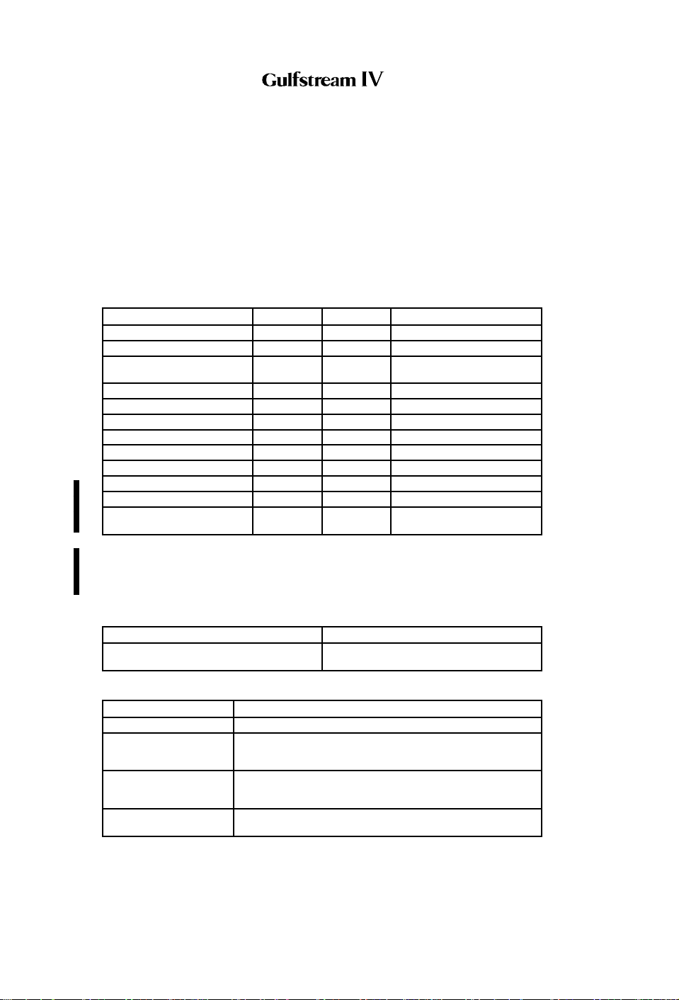
3. Controls and Indications:
(See Figure 6 and Figure 7 through Figure 9.)
A. Circuit Breakers (CBs):
Circuit Breaker Name: CB Panel: Location: Power Source:
SHAKER #1 CPO A-10 Essential DC Bus
SHAKER #2 CPO B-10 R Main DC Bus
STALL BARR DUMP
VALVE
CPO A-8 Essential DC Bus
STALL BARR VALVE #1 CPO A-12 Essential DC Bus
STALL BARR VALVE #2 CPO B-12 R Main DC Bus
STALL BARRIER #1 CPO A-9 Essential DC Bus
STALL BARRIER #2 CPO B-9 R Main DC Bus
STALL WARN CMPTR #1 CPO A-11 Essential DC Bus
STALL WARN CMPTR #2 CPO B-11 R Main DC Bus
ELEV COMB HYD S/O (1) CPO B-15 Essential DC Bus
ELEV FLT HYD S/O (1) CPO A-15 Essential DC Bus
ELEV TRIM TAB ACTR
HTR (2)
CP L-9 L Main AC Bus, φC
NOTE(S):
(1) CAA certified aircraft only.
(2) SN 1380 & subs; SN 1000 - 1379 having ASC 342.
B. Warning (Red) Messages and Annunciations:
Annunciation: Cause or Meaning:
Red chevron illuminated on pilot’s /
copilot’s AOA indexer.
AOA for approach and landing is too
high.
C. Caution (Amber) Messages and Annunciations:
CAS Message: Cause or Meaning:
AOA HEAT 1-2 FAIL Angle of attack probe heater failed.
EL CMB HYD OFF (1) The flight control automatic failure detection system has
EL FLT HYD OFF (1) The flight control automatic failure detection system has
EL MISTRIM NOSE
UP/DN
shut off Combined hydraulic system pressure to the
elevator actuator.
shut off Flight hydraulic system pressure to the elevator
actuator.
Autopilot elevator trim out of trim in direction indicated.
PRODUCTION AIRCRAFT SYSTEMS2A-27-00
Page 14
January 31/02
Revision 6
Page 13
OPERATING MANUAL
CAS Message: Cause or Meaning:
MACH TRIM LIMIT Elevator trim has reached electrical trim limit while
MACH TRIM OFF PITCH TRIM switch selected OFF or electric pitch trim has
operating airplane in Mach Trim speed region (greater
than 0.80 Mach).
failed. (This message is inhibited at less than 0.82 Mach.)
STALL BARRIER 1-2 Stall barrier system giving stall angle indication.
STALL BARR 1-2 FAIL Stall barrier failed.
It is normal for STALL BARR 1 FAIL message to be
displayed any time EMERGENCY FLAPS are used and
flaps position is greater than 22°.
STALL BARRIER OFF STALL BARRIER switch is OFF or system not powered.
TRIM LIMIT Autopilot elevator trim has reached electrical trim limits.
NOTE(S):
(1) CAA certified aircraft only.
Annunciation: Cause or Meaning:
Amber chevron illuminated on pilot’s/
copilot’s AOA indexer.
AOA for approach and landing is too low.
4. Limitations:
A. Angle-of-Attack (AOA) System:
(1) Use As A Reference:
Angle-of-Attack (AOA) may be used as reference, but does not
replace airspeed as the primary reference.
(2) Indication Parameters:
AOA indication must be within white band once forward airspeed is
attained during takeoff roll.
(3) Use As A Speed Reference:
AOA shall not be used as a speed reference for takeoff rotation.
B. Stall Barrier / Stall Warning:
(1) Takeoff Requirements:
Both stall warning / stall barrier systems must be operative for
takeoff.
(2) Use of System:
Stall barrier systems must be ON during all flight operations except
as noted in Section 05-15-40, Stall Barrier Malfunction. Refer to this
system description for a description of the stall warning / stall barrier
system checkout procedure.
C. Mach Trim Compensation / Electric Elevator Trim:
(1) Use of mach trim compensation:
Mach trim compensation must be ON during all flight operations
except as provided for in Section 05-03-40, Mach Trim
Compensation Failure.
(2) If mach trim compensation failure is coupled with yaw damper
failure:
When mach trim compensation failure is coupled with yaw damper
PRODUCTION AIRCRAFT SYSTEMS 2A-27-00
Page 15
January 31/02
Revision 6
Page 14

OPERATING MANUAL
failure, observe speed limitations for both failures and limit altitude
to 41,000 ft.
D. Mach Trim / Electric Elevator Trim Inoperative Speed:
With both mach trim compensators inoperative or electric elevator trim
inoperative, the maximum operating limit speed is 0.75 MT.
Page 16
January 31/02
PRODUCTION AIRCRAFT SYSTEMS2A-27-00
Revision 6
Page 15
OPERATING MANUAL
Pitch Flight Control
System Simplified Block
Diagram
Figure 3
2A-27-00
Page 17 / 18
January 31/02
Page 16
OPERATING MANUAL
Stall Barrier / Angle of
Attack Wiring Schematic
Figure 4
2A-27-00
Page 19 / 20
January 31/02
Page 17
OPERATING MANUAL
Pitch Trim Controls
Figure 5
2A-27-00
Page 21 / 22
January 31/02
Page 18
OPERATING MANUAL
Stall Barrier / Angle of
Attack Controls and
Indications
Figure 6
2A-27-00
Page 23 / 24
January 31/02
Page 19
OPERATING MANUAL
Control Columns
Figure 7
PRODUCTION AIRCRAFT SYSTEMS 2A-27-00
Page 25
January 31/02
Revision 6
Page 20

OPERATING MANUAL
Page 26
January 31/02
FLIGHT POWER SHUT OFF Handle
Figure 8
PRODUCTION AIRCRAFT SYSTEMS2A-27-00
Revision 6
Page 21
OPERATING MANUAL
Yaw Damper / Pitch Trim Control Panel
Figure 9
PRODUCTION AIRCRAFT SYSTEMS 2A-27-00
Page 27
January 31/02
Revision 6
Page 22
OPERATING MANUAL
Page 28
January 31/02
Stall Barrier Simplified Block Diagram
Figure 10
PRODUCTION AIRCRAFT SYSTEMS2A-27-00
Revision 6
Page 23
OPERATING MANUAL
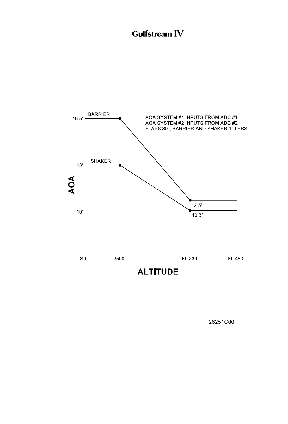
Stall Barrier / Angle of Attack Warning Parameters
Figure 11
PRODUCTION AIRCRAFT SYSTEMS 2A-27-00
Page 29
January 31/02
Revision 6
Page 24

OPERATING MANUAL
2A-27-30: Yaw Flight Control System
1. General Description:
Aircraft movement about the vertical axis (yaw) is controlled by the position of a
single rudder. The rudder is both manually (rudder pedals) and electrically (yaw
damper) controlled, mechanically actuated and hydraulically boosted. It is
mounted on the trailing edge of the vertical stabilizer. Total rudder travel ranges
from 22° left or right of neutral.
The rudder is positioned by an electrohydraulic servoactuator located in the tail
compartment. The actuator receives hydraulic operating pressure simultaneously
from the Combined and Flight hydraulic systems during normal operations. In the
event of total loss of hydraulic pressure in both systems, the rudder reverts to
manual operation. Manual reversion is also possible through use of a flight power
shutoff valve and its pedestal-mounted control handle.
A rudder trim system is used to position the entire rudder surface (no trim tab is
incorporated). Manual trim is accomplished by a pedestal-mounted control knob.
A yaw damping system is incorporated to provide stability augmentation about the
vertical axis by counteracting any dutch roll tendency. Electrical inputs made by
the yaw damper to the rudder actuator are transparent to the flight crew and can
be made simultaneously with other inputs from the flight crew.
On CAA certified aircraft,aflight control automatic failure detection system
compares rudder pedal inputs to rudder actuator outputs. If a malfunction is
detected, the system shuts off either or both hydraulic power sources to the
actuator.
The yaw flight control system consists of the following subsystems, units and
components:
• Rudder pedal system
• Mechanical actuation system
• Hydraulic boost system
• Manual reversion system
• Rudder load limiting system
• Yaw damper system
• Yaw trim system
• Failure detection system (CAA aircraft only)
2. Description of Subsystems, Units and Components:
A. Rudder Pedal System:
(See Figure 13.)
Each pair of rudder pedals functions both as a conventional rudder control
and toe brake control. With nosewheel steering operating, limited steering
control (7° left and right of neutral) is also available using the rudder
pedals.
Each pilot can adjust the resting position of their rudder pedals to enhance
comfort and usability. Lifting an adjusting lever located between each pair
of rudder pedals releases a lock to permit fore and aft adjustment. The
lever handle is then pulled aft or pushed forward, moving the rudder pedal
set in the same direction. Once in the desired position, releasing the lever
locks the pedals in place.
Page 30
January 31/02
PRODUCTION AIRCRAFT SYSTEMS2A-27-00
Revision 6
Page 25

OPERATING MANUAL
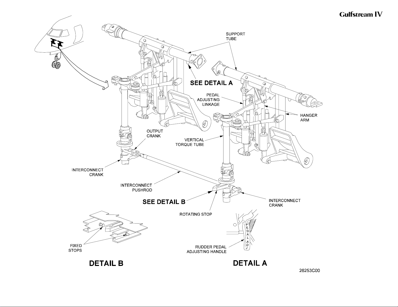
Each individual rudder pedal attaches to a pedal hanger arm that pivots
fore and aft on a lateral support tube. A rod assembly connected between
each pedal hanger arm and a vertical torque tube translates the fore and
aft movement of the pedal into rotational movement of the vertical torque
tube. An interconnect pushrod between the bases of the left and right
torque tubes interconnects the pilot’s and copilot’s rudder pedal sets. An
output crank attached to base of the right (copilot’s) torque tube ties the
rudder pedals to the rudder mechanical actuation system. A rotating lugtype stop attached to base of the left (pilot’s) torque tube limits rudder
pedal travel when it contacts either one of two adjustable stop bolts.
Artificial feel forces are supplied by a spring bungee attached to the rudder
actuator input cable sector. The bungee provides a resistant force
proportional to rudder pedal displacement.
B. Mechanical Actuation System:
(See Figure 12.)
Rudder pedal inputs are transmitted rearward through a system of push-
pull rods, bellcranks, cables and a sector assembly to an input cable sector
near the base of the rudder in the tail compartment. As the right torque tube
rotates, its output crank moves an attached pushrod forward and aft. The
pushrod transmits this movement through a motion reversing crank and
another pushrod to a cable sector. Cables from the cable sector transmit
control inputs rearward to an input cable sector. Movement of the input
cable sector then drives the rudder actuator servo control valve through an
input crank arm.
C. Hydraulic Boost System:
(See Figure 12.)
The rudder actuator is a dual tandem actuator consisting of two pistons
secured to a common shaft. The pistons move inside a common cylinder
divided to create two separate cylinders. One cylinder receives Flight
hydraulic system pressure while the other cylinder receives Combined
hydraulic system pressure.
Mechanical movement of the actuator input crank arm moves the servo
control valve from its neutral position. The servo control valve then directs
hydraulic pressure to one of the actuator’s two cylinders and connects
each cylinder’s opposite side to return. Movement of the actuator then
drives the rudder through an output crank, pushrod, and horn and tube
combination. When the rudder reaches the desired deflection, the servo
control valve shifts to its neutral position to lock hydraulic pressure within
the actuator, in effect preventing further surface movement.
The input cable sector and output crank are connected through a center
rear crank through a pin and slot arrangement. This pin and slot
arrangement creates 4° of differential motion between the input cable
sector and the output crank, allowing maximum servo control valve
displacement while providing a total of 3° of yaw damper authority.
D. Manual Reversion System:
During normal flight operations, the Combined and Flight hydraulic
systems each supply and maintain pressure to the rudder actuator. Loss of
system pressure from both hydraulic systems will automatically revert the
yaw flight control system to manual control. As pressure at the actuator
PRODUCTION AIRCRAFT SYSTEMS 2A-27-00
Page 31
January 31/02
Revision 6
Page 26

OPERATING MANUAL
drops below 75 psi, bypass valves within the actuator open to allow the
actuator piston to idle. With the actuator piston idling, the system is said to
be in manual reversion, technically explained in the following paragraph.
The input cable sector and output crank rotate on a mutually independent
common pivot. They are linked by a pin and elongated slot arrangement.
The input crank is on the pin and the output crank is on the slot. With the
actuator piston idling, the pin moves within the slot until it reaches either
end. At this point, mechanical contact is made and the input cable sector
now drives the output crank. The output crank, in turn, drives the rudder
through its push-pull rods and cranks.
Manual reversion of the yaw flight control system is also possible by
closing a normally open flight power shutoff valve. The flight power shutoff
valve is a mechanically operated shutoff valve located between the
Combined and Flight hydraulic system pressure sources and the rudder
actuator (as well as the aileron, elevator and flight / ground spoiler
actuator) pressure lines. The valve consists of two mechanically connected
but hydraulically isolated sections. A controlex cable connects the valve to
a FLIGHT POWER SHUT OFF handle located on the left aft side of the
cockpit center pedestal. See Figure 8.
Moving the FLIGHT POWER SHUT OFF handle up from its stowed
(horizontal) position to the vertical position mechanically closes the flight
power shutoff valve. With the valve closed, operating pressure is removed
from the actuator, allowing the piston to idle.
The resultant advantage of the flight power shutoff provision is the ability to
bypass a malfunctioning actuator (such as would be the need in the
unlikely event of an actuator jam) and manually fly the aircraft. Although
rudder pedal effort and response time to inputs are increased while in
manual reversion, the aircraft remains capable of positive and harmonious
control.
E. Rudder Load Limiting System:
(See Figure 12.)
Load-limiting (force-modulating) valves inside the rudder actuator restrict
Combined and Flight hydraulic system pressure to prevent vertical
stabilizer structural overload. Surface movement is limited by these valves
when higher airspeeds increase the airloads imposed against the rudder.
When the hinge moment limit is reached, the force-modulating shift,
reducing pressure to a maximum of approximately 2,250 psi, regardless of
hydraulic system pressure. Operation of either valve to restrict hydraulic
pressure closes an internal microswitch that triggers a blue RUDDER
LIMIT advisory CAS message. With the RUDDER LIMIT message
displayed, further displacement of the rudder surface is inhibited.
When on the ground with the Combined hydraulic system operating, rudder
actuator load limiting can be checked by applying gradual input force to the
rudder pedals until the rudder surface is bottomed against its stops (left or
right). The RUDDER LIMIT advisory CAS message will be displayed at the
instant of pressure limiting within the actuator. Flight crews are cautioned
that both the gust lock and nose wheel steering must be OFF before
performing this test. Also, it should be noted that if performing this test with
only the Flight hydraulic system operating, the RUDDER LIMIT message
may or may not be displayed.
Page 32
January 31/02
PRODUCTION AIRCRAFT SYSTEMS2A-27-00
Revision 6
Page 27

OPERATING MANUAL
In the event of a malfunction or failure of internal rudder actuator load
limiting, redundant limiting is provided by an additional external load
limiting valve installed upstream of the rudder actuator. With this
configuration, continuous rudder load limiting is afforded as either load
limiting valve (internal or external) will limit output pressure. The external
load limiting valve limits total hydraulic pressure to a maximum of 2,650
(Combined and Flight systems) to the rudder actuator.
The external load limiting valve is checked by observing CAS for display of
an amber SNGL RUDDER LIMIT caution message. Proper operation of the
valve is indicated by display of the message during the following sequence:
• Before starting engines (power on) — message displayed
• Right engine only operating — message displayed
• Both engines operating — message not displayed
Proper operation of the valve can also be verified during the following
sequence:
• 0 psi Combined pressure / 3,000 psi Flight pressure — message
displayed
• 3,000 psi Combined pressure / 3,000 psi Flight pressure —
message not displayed
• 3,000 psi Combined pressure / 0 psi Flight pressure — message not
displayed
F. Yaw Damper System:
A series mode yaw damper is incorporated into the rudder actuator.
Controlled by the autopilot, the yaw damper provides stability
augmentation by automatically counteracting any dutch roll tendency within
the aircraft. The system is referred to as a series mode system in that no
feedback is provided through the rudder pedals.
The yaw damper system consists of a solenoid-operated shutoff valve,
transfer valve, servo ram and summing lever / transducer. Electrical power
is supplied to the system through the Right Main and Essential 28 VDC
buses. Hydraulic power is supplied to the system by the Flight hydraulic
system only.
Located on the pilot’s flight panel, the YAW DAMP ENG / DISENG switch
engages or disengages the yaw damper. With the yaw damper engaged
(amber DISEN switch legend extinguished), 28 VDC power energizes the
solenoid-operated shutoff valve to the open position. Flight hydraulic
system pressure then flows to the transfer valve. Hydraulic pressure flow
and volume through the transfer valve is controlled by the torque motor
using a jet pipe / receiver pipe arrangement. The yaw damper / pitch trim
control panel is shown in Figure 9.
Depending on commands provided by the autopilot, the torque motor
positions a jet pipe to direct hydraulic pressure to two receiver pipes inside
the transfer valve. If equal commands are sent by the autopilot, the jet pipe
remains in a centered, or null, position. When unequal commands are sent,
the torque motor deflects the jet pipe in the necessary direction to supply
more pressure to one receiver pipe than the other. This shifts the transfer
valve spool and hydraulic pressure flows from the transfer valve to the
servo ram.
PRODUCTION AIRCRAFT SYSTEMS 2A-27-00
Page 33
January 31/02
Revision 6
Page 28

OPERATING MANUAL
Under hydraulic pressure, the servo ram then moves in the desired
direction to reposition the rudder actuator servo control valve which, in turn,
results in rudder movement.
As the system moves the rudder, a summing lever / transducer assembly
provides position information to the yaw servo amplifier. The servo
amplifier, in turn, nulls the signal to the transfer valve.
G. Yaw Trim System:
Trim control about the vertical axis is controlled by displacing the entire
rudder surface (there is no rudder trim tab). This is accomplished through
the use of a rudder trim control wheel mounted on the upper aft end of the
center pedestal, shown in Figure 14.
Rotation of the rudder trim control wheel left or right rotates a cable drum
below the cockpit floor through the use of a torque tube. As the drum
rotates, cables transmit the movement to a screw-type rudder trim actuator.
The actuator, in turn, extends and retracts, repositioning the rudder
actuator input cable sector through the trim actuator attachment to the
artificial feel bungee. Movement of the input cable sector provides input to
the rudder actuator servo control valve, thus driving the rudder to effect trim
position.
Since the are no stops incorporated in the rudder trim actuator, total travel
is determined by integral stops in the rudder trim control wheel. Total trim
wheel travel is approximately 6½ turns from stop to stop. This yields a
maximum of 10 units (7.5°) NOSE L (left) and 10 units (7.5°) NOSE R
(right) of rudder deflection from the neutral position.
H. Failure Detection System:
CAA Certified Aircraft Only: A flight control automatic failure detection
system monitors flight control inputs from the rudder pedals and compares
them to the rudder actuator outputs. If the system detects a failure, it
automatically shuts off hydraulic pressure to the actuator and triggers the
appropriate warning on the Crew Alerting System (CAS). Once activated by
a malfunction, hydraulic pressure is inhibited until power to the respective
monitoring system is interrupted, for instance, by pulling and resetting the
appropriate circuit breaker.
The monitoring system is a dual-channel system. One channel controls the
Combined hydraulic system pressure source while the other controls the
Flight hydraulic system pressure source. Power for the system is received
from the 28 VDC Essential DC bus.
A pair of limit switches monitor applied rudder pedal input while a pair of
reed switches monitor actuator output in response to the input.
If a disagreement occurs between rudder pedal input and actuator output,
the associated limit switch and reed switch close to complete a circuit to
the respective hydraulic shutoff delay relay. If the relay remains energized
for more than ½ second, it energizes the respective hydraulic shutoff
control relay.The control relay, in turn, powers its hydraulic shutoff valve to
the closed position. Activation of the shutoff valve also causes an amber
RD CMB HYD OFF (or RD FLT HYD OFF) message to be displayed on
CAS.
Page 34
January 31/02
PRODUCTION AIRCRAFT SYSTEMS2A-27-00
Revision 6
Page 29
OPERATING MANUAL
3. Controls and Indications:
(See Figure 9 and Figure 14.)
A. Circuit Breakers (CBs):
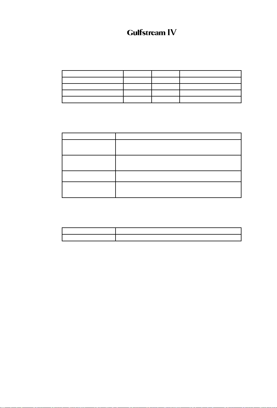
Circuit Breaker Name: CB Panel: Location: Power Source:
STABAUG SERVO #1 CPO A-6 Essential DC Bus
STABAUG SERVO #2 CPO B-6 R Main DC Bus
RUD COMB HYD S/O (1) CPO C-14 Essential DC Bus
RUD FLT HYD S/O (1) CPO A-16 Essential DC Bus
NOTE(S):
(1) CAA certified aircraft only.
B. Caution (Amber) Messages and Annunciations:
CAS Message: Cause or Meaning:
RD CMB HYD OFF (1) The flight control automatic failure detection system has
RD FLT HYD OFF (1) The flight control automatic failure detection system has
SNGL RUDDER LIMIT Failure of input pressure load limiter (with Flight and
YAW DAMPER OFF Yaw damper (YAW DAMP ENG / DISENG) switch is OFF.
shut off Combined hydraulic system pressure to the rudder
actuator.
shut off Flight hydraulic system pressure to the rudder
actuator.
Combined Hydraulic System pressure normal.)
OR:
Yaw damper failure.
NOTE(S):
(1) CAA certified aircraft only.
C. Advisory (Blue) Messages and Annunciations:
CAS Message: Cause or Meaning:
RUDDER LIMIT Rudder actuator torque limiter is in operation.
4. Limitations:
A. Yaw Damper Limitations:
(1) If yaw damper fails prior to takeoff:
Maximum fuel quantity permitted for takeoff is 9000 lb (4082 kg).
(2) If yaw damper fails in flight:
(a) Above 18,000 feet:
Maintain airspeed at or above 220 KCAS.
(b) Below 18,000 feet:
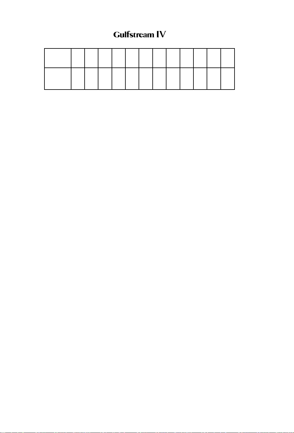
Maintain airspeed as a function of fuel quantity at or above
that shown on the following table until ready to configure for
approach and landing.
PRODUCTION AIRCRAFT SYSTEMS 2A-27-00
Page 35
January 31/02
Revision 6
Page 30
OPERATING MANUAL
Fuel Qty
-
8 1012141618202224262830
1000 Lb
Minimum
Airspeed
KCAS
96 107 117 126 135 143 151 158 165 172 178 184
B. Mach Trim Compensation / Electric Elevator Trim:
(1) Use of mach trim compensation:
Mach trim compensation must be ON during all flight operations
except as provided for in Section 05-03-40, Mach Trim
Compensation Failure.
(2) If mach trim compensation failure is coupled with yaw damper
failure:
When mach trim compensation failure is coupled with yaw damper
failure, observe speed limitations for both failures and limit altitude
to 41,000 ft.
Page 36
January 31/02
PRODUCTION AIRCRAFT SYSTEMS2A-27-00
Revision 6
Page 31
OPERATING MANUAL
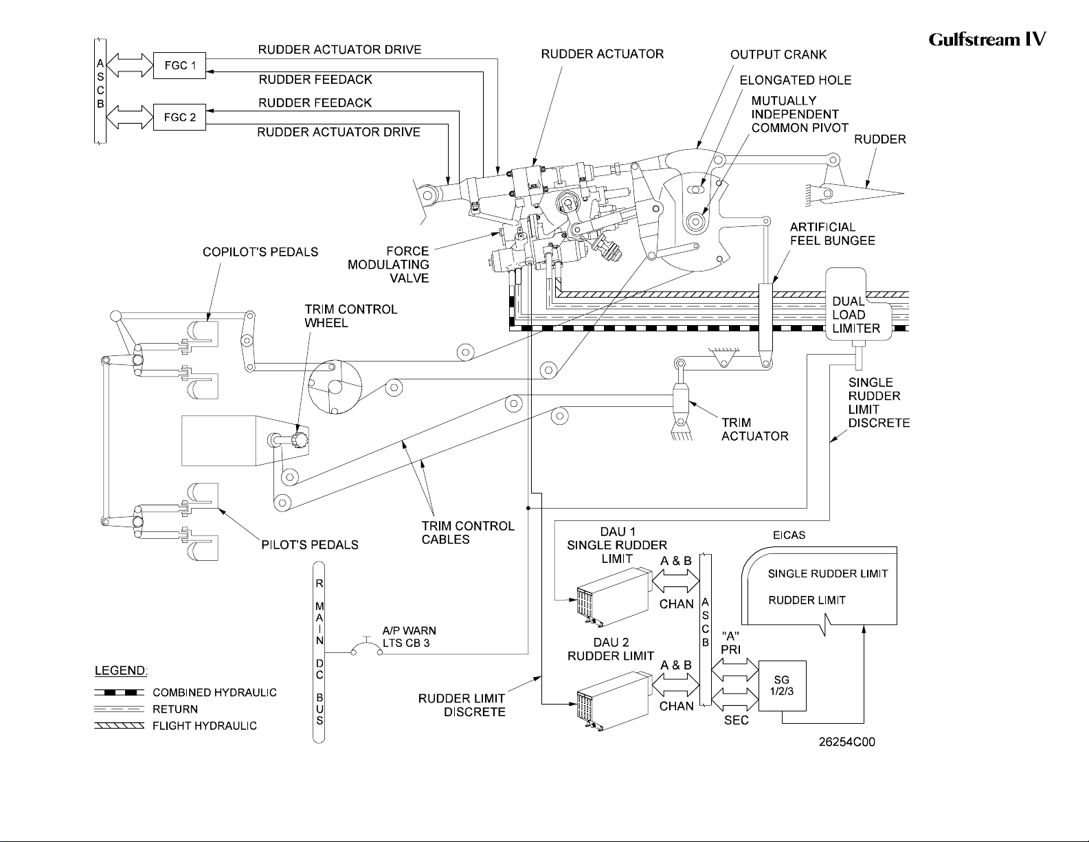
Yaw Flight Control System
Simplified Block Diagram
Figure 12
2A-27-00
Page 37 / 38
January 31/02
Page 32
OPERATING MANUAL
Rudder Pedals / Forward
Linkage
Figure 13
2A-27-00
Page 39 / 40
January 31/02
Page 33
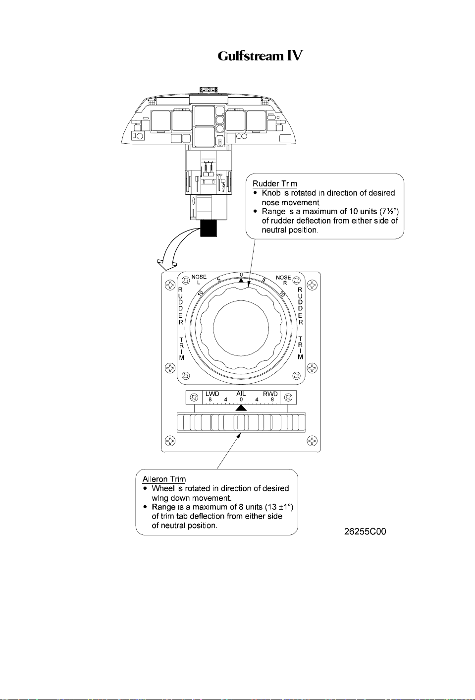
OPERATING MANUAL
Yaw Trim / Roll Trim Control Wheels
Figure 14
PRODUCTION AIRCRAFT SYSTEMS 2A-27-00
Page 41
January 31/02
Revision 6
Page 34

OPERATING MANUAL
2A-27-40: Roll Flight Control System
1. General Description:
Aircraft movement about the longitudinal axis (roll) is controlled by the position of
the ailerons. The ailerons are manually (control wheel) or electrically (autopilot
servo) controlled, mechanically actuated and hydraulically boosted airfoils
mounted on the trailing edge of each wing. Total aileron travel ranges from 10°
trailing edge up to 10° trailing edge down.
Each aileron is positioned by a tandem type hydraulic actuator. The actuator
receives hydraulic operating pressure simultaneously from both the Combined
and Flight hydraulic systems during normal operations. Loss of a single hydraulic
system has no effect on operation of the ailerons, as the remaining system is
capable of maintaining actuator load capacity. In the event of total loss of
hydraulic pressure in both systems, the ailerons revert to manual operation.
Manual reversion is also possible through use of a flight power shutoff valve and
its pedestal-mounted control handle.
Flight spoilers are incorporated into the roll flight control system to improve aircraft
roll response. During roll, the spoilers respond to upward movement of the
ailerons while the opposite spoilers remain flush to the wing as the opposite
aileron travels downward. Spoiler travel varies in proportion to the degree of the
roll, to maximum extension of 26 ±2° (55 +4/-3° with speed brakes extended). The
flight spoiler system is solely a hydraulically powered system, thus reversion to
manual control is not possible.
A roll trim system is used to position a trim tab attached to the trailing edge of the
left aileron. The tab is positioned manually by a pedestal-mounted control wheel.
On CAA certified aircraft,aflight control automatic failure detection system
monitors forces within the roll flight control system. If a malfunction is detected,
the system shuts off both hydraulic power sources to the affected actuator.
The roll flight control system consists of the following subsystems, units and
components:
• Control wheel system
• Mechanical actuation system
• Hydraulic boost system
• Manual reversion system
• Flight spoiler system
• Roll trim system
• Failure detection system (CAA aircraft only)
2. Description of Subsystems, Units and Components:
A. Control Wheel System:
(See Figure 7.)
A control wheel mounted on top of the left and right control column is used
for roll control. Each control wheel has the following controls incorporated:
• Pitch trim (NOSE UP / NOSE DOWN)
• Map light (MAP)
• Transponder identification (IDENT)
• Touch control steering (TCS)
Page 42
January 31/02
PRODUCTION AIRCRAFT SYSTEMS2A-27-00
Revision 6
Page 35

OPERATING MANUAL
• Autopilot / stall barrier disconnect (A/P DISC / BARR DISC)
• Radio / intercom push-to-talk (RADIO / ICS)
A torque shaft in the top of the control column transmits left and right
control wheel movement through a universal joint to a vertical torque tube
that descends through the column. The torque tube, in turn, connects to a
two-armed crank at the base of the column. On the rear facing arm of the
crank, a pushrod assembly interconnects the pilot’s and copilot’s control
wheels. The aileron control cables are connected to the outboard facing
arm of the crank. Non-adjustable stops in the control column limit control
wheel movement to 90° left or right of neutral.
B. Mechanical Actuation System:
(See Figure 15.)
Control wheel inputs are transmitted rearward through a synchronized
system of pushrods, bellcranks, cables and sector assemblies. The system
transmits the inputs to the outboard sector assembly. The outboard sector
assembly operates the pushrods and bellcranks that form the input and
output cranks. Cradled between these cranks is the aileron actuator. The
leverage ratio of the input and output cranks provides a 5:1 boost ratio, i.e.,
one unit of work supplied by the flight crew through the control wheel
results in five units of work provided by the actuator. Movement of the input
and output cranks about a common pivot point displaces the aileron
actuator servo control valve input lever.
C. Hydraulic Boost System:
The aileron actuator is a dual tandem actuator consisting of two pistons
secured to a common shaft. The pistons move inside a common cylinder
divided to create two separate cylinders. One cylinder receives Flight
hydraulic system pressure while the other cylinder receives Combined
hydraulic system pressure.
Mechanical movement of the actuator input lever moves the servo control
valve from its neutral position. The servo control valve then directs
hydraulic pressure to one of the actuator’s two cylinders and connects
each cylinder’s opposite side to return. When the aileron reaches the
desired deflection, the servo control valve shifts to its neutral position to
lock hydraulic pressure within the actuator, in effect preventing further
surface movement.
D. Manual Reversion System:
During normal flight operations, the Combined and Flight hydraulic
systems each supply and maintain 3000 psi to the aileron actuators. Loss
of system pressure due to a single system failure has no effect on
operation of the roll flight control system.
Loss of system pressure from both hydraulic systems will automatically
revert the roll flight control system to manual control. As pressure at each
actuator drops below 60 psi, bypass valves within the actuator open to
allow the actuator piston to idle. With the actuator piston idling, the system
is said to be in manual reversion. The ailerons are now controlled solely by
mechanical means; the flight spoilers are inoperative.
Manual reversion of the roll flight control system is also possible by closing
a normally open flight power shutoff valve. The flight power shutoff valve is
PRODUCTION AIRCRAFT SYSTEMS 2A-27-00
Page 43
January 31/02
Revision 6
Page 36

OPERATING MANUAL
a mechanically operated shutoff valve located between the Combined and
Flight hydraulic system pressure sources and the aileron actuators (as well
as the elevator, rudder and flight / ground spoiler actuator) pressure lines.
The valve consists of two mechanically connected but hydraulically
isolated sections. A controlex cable connects the valve to a FLIGHT
POWER SHUT OFF handle located on the left aft side of the cockpit center
pedestal. See Figure 8.
Moving the FLIGHT POWER SHUT OFF handle up from its stowed
(horizontal) position to the vertical position mechanically closes the flight
power shutoff valve. With the valve closed, operating pressure is removed
from the actuator, allowing the piston to idle.
The resultant advantage of the flight power shutoff provision is the ability to
bypass a malfunctioning actuator (such as would be the need in the
unlikely event of an actuator jam) and manually fly the aircraft. Although
control wheel effort and response time to inputs are increased while in
manual reversion, the aircraft remains capable of positive and harmonious
control.
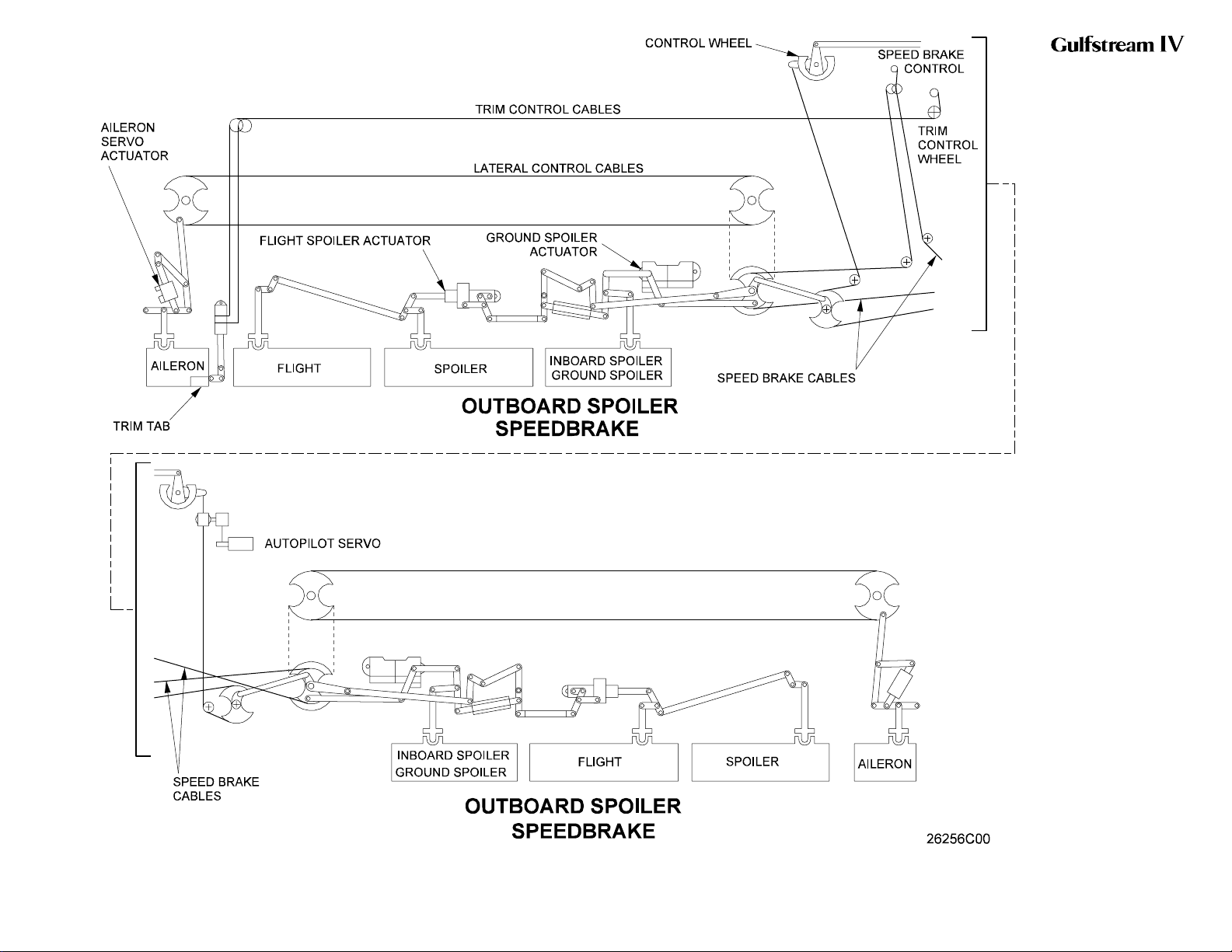
E. Flight Spoiler System:
(See Figure 15.)
A mixing linkage between the aileron and flight spoiler control mechanisms
mixes control wheel inputs to provide aileron / flight spoiler coordination.
This allows the two outboard spoiler panels on the same side as an upward
moving aileron to extend up to a maximum of 26 ±2° for roll control. If the
speed brakes are extended, the flight spoilers extend up to a maximum of
55 +4/-3°.
As the aileron control mechanism commands an aileron to deflect upward,
the mixing linkage transmits an extend command to the flight spoiler
actuator control valve through push-pull rods, bellcranks and cables. The
control valve then shifts to direct pressure to the flight spoiler actuator. The
normally-extended actuator retracts and the flight spoiler panels follow
aileron movement to assist roll control. The flight spoiler panels on the
opposite wing remain retracted.
F. Roll Trim System:
(See Figure 14 and Figure 15.)
Trim control about the longitudinal axis is controlled by displacing a trim tab
attached to the trailing edge of the left aileron. This is accomplished
through the use of an aileron trim control wheel mounted on the upper aft
end of the center pedestal.
Rotation of the aileron trim control wheel left or right rotates a cable drum
through the use of a torque tube. As the drum rotates, cables transmit the
movement to the aileron trim actuator. Mechanical linkage attached to the
actuator causes the trailing edge of the aileron trim tab to be raised or
lowered.
Movement of the aileron trim control wheel also drives an incorporated
pointer that indicates the units of Left Wing Down (LWD) or Right Wing
Down (RWD) trim from neutral. Total trim wheel travel is approximately 4½
turns from stop to stop. This yields a maximum of 8 units (13 ±1°) of trim
tab deflection from either side of the neutral position.
Page 44
January 31/02
PRODUCTION AIRCRAFT SYSTEMS2A-27-00
Revision 6
Page 37
OPERATING MANUAL
If an attempt is made to force the aileron trim control wheel past its
mechanical stops, a shear pin breaks to disconnect the control wheel from
the torque tube, disabling roll trim.
G. Failure Detection System:
CAA Certified Aircraft Only: A flight control automatic failure detection
system monitors force applied to the aileron input / manual reversion rod,
providing detection of a jammed or malfunctioning aileron actuator. If the
system detects a failure, it automatically shuts off all hydraulic pressure to
that actuator (the opposite actuator remains unaffected) and triggers the
appropriate warning on the Crew Alerting System (CAS).
With the roll flight control system operating normally, forces on the aileron
input / manual reversion rod remain relatively low because there is no lag
between control wheel input and actuator output. If an actuator
malfunctions resulting in an aileron hardover action, force levels on the rod
increase significantly. When this force exceeds 150 pounds, a force-link
limit switch closes to energize an associated time delay relay.
Similarly, a jammed actuator results in increased control inputs being
applied by the flight crew. If these control inputs exceed approximately 20
pounds, the force-link limit switch closes to energize an associated time
delay relay.
If the time delay relay remains energized for more than ½ second, it
energizes a shutoff relay. The shutoff relay, in turn, powers the actuator’s
Combined and Flight hydraulic system shutoff valves to the closed position.
Closing of the shutoff valves also causes an amber L-R AIL HYD OFF
message to be displayed on CAS.
3. Controls and Indications:
(See Figure 14.)
A. Circuit Breakers (CBs):
Circuit Breaker Name: CB Panel: Location: Power Source:
L AIL HYD S/O (1) CPO A-14 Essential DC Bus
R AIL HYD S/O (1) CPO B-14 Essential DC Bus
NOTE(S):
(1) CAA certified aircraft only.
B. Caution (Amber) Messages and Annunciations:
CAS Message: Cause or Meaning:
L AIL HYD OFF (1) The flight control automatic failure detection system has
R AIL HYD OFF (1) The flight control automatic failure detection system has
RETRIM L-R WING
DOWN
shut off Combined and Flight hydraulic system pressure to
the left aileron actuator.
shut off Combined and Flight hydraulic system pressure to
the right aileron actuator.
Lateral axis out of trim.
NOTE(S):
(1) CAA certified aircraft only.
PRODUCTION AIRCRAFT SYSTEMS 2A-27-00
Page 45
January 31/02
Revision 6
Page 38

OPERATING MANUAL
4. Limitations:
There are no limitations established for the roll flight control system at the time of
this revision.
Page 46
January 31/02
PRODUCTION AIRCRAFT SYSTEMS2A-27-00
Revision 6
Page 39
OPERATING MANUAL
Roll Flight Control System
Simplified Block Diagram
Figure 15
2A-27-00
Page 47 / 48
January 31/02
Page 40

OPERATING MANUAL
2A-27-50: Horizontal Stabilizer System
1. General Description:
A movable horizontal stabilizer provides automatic longitudinal trim assistance to
compensate for the nose pitchdown moment (tuck-in) associated with flap
extension. Stabilizer position (leading edge angle of incidence) is a direct function
of flap position, as the stabilizer is mechanically driven from the flap central
gearbox. If a malfunction occurs rendering the stabilizer immovable, a safe
landing can be made using normal pitch trim.
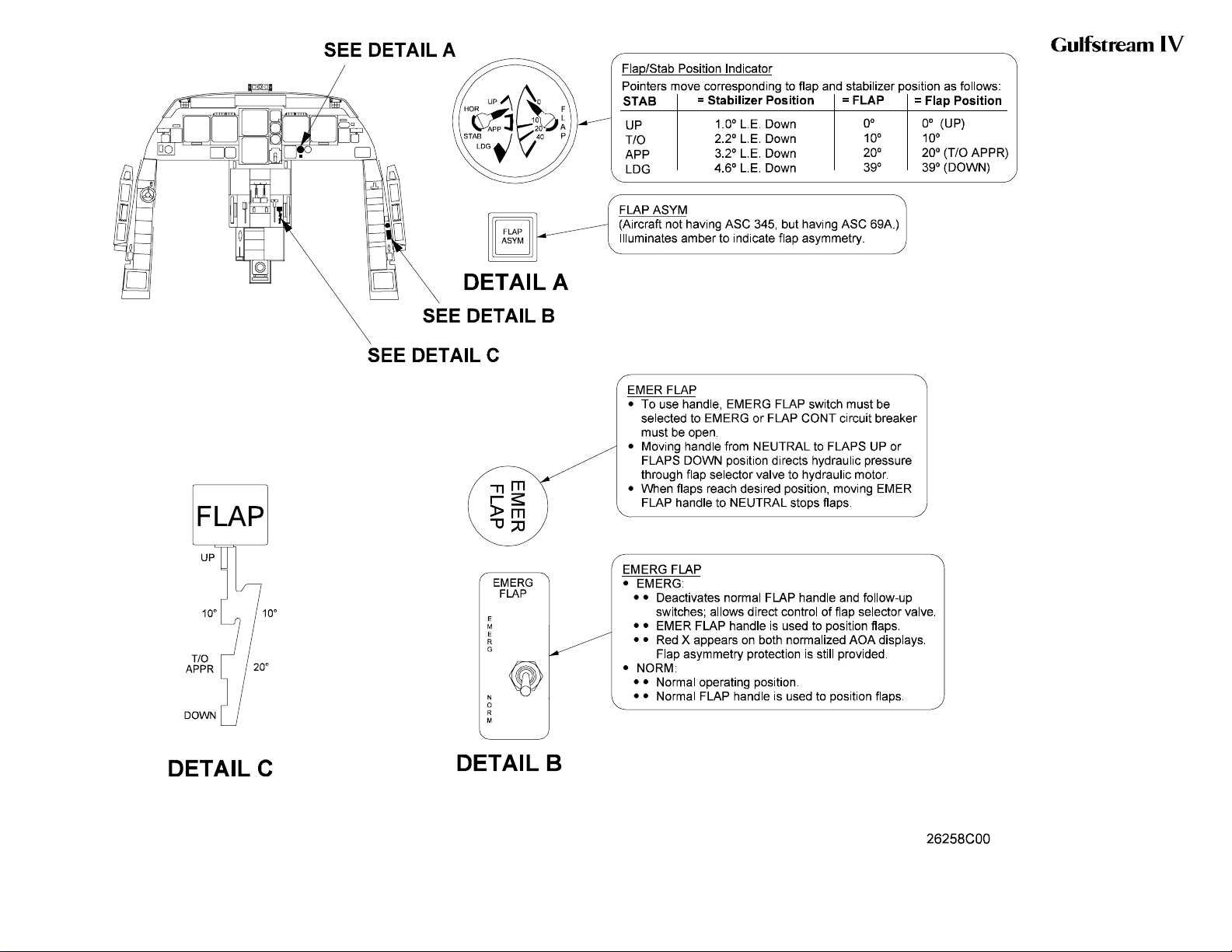
Horizontal stabilizer position is displayed on the FLAP / STAB position indicator
located on the copilot’s skirt panel.
The horizontal stabilizer system is composed of the following subsystems, units
and components:
• Stabilizer drive system
• Torque limiter
• Dwell box
• Stabilizer actuator
• Stabilizer position and warning system
2. Description of Subsystems, Units and Components:
(See Figure 16 and Figure 17.)
A. Stabilizer Drive System:
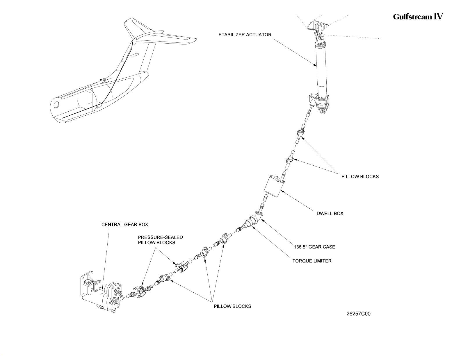
The stabilizer drive system consists of torque shafts installed beginning
from the aft side of the flap central gearbox, rearward through the tail
compartment via a dwell box, then upward through the vertical stabilizer to
the stabilizer actuator. Bearing housings and pillow blocks installed at
defined intervals support the torque shafts, preventing whiplash as they
rotate.
B. Torque Limiter:
A torque limiter is installed at the input side of the central gearbox. If the
gearbox, dwell box or stabilizer actuator should jam or fail, the torque
limiter spring jams to lock the torque shafts. This stalls the central gearbox
hydraulic motor, stopping further flap and horizontal stabilizer movement.
If a torque shaft fails, the flaps are still operable throughout their full range.
The stabilizer, however, remains at its last position prior to shaft failure. The
flight crew would then use pitch trim as necessary to compensate for the
immovable stabilizer.
C. Dwell Box:
Adwell box, located in the tail compartment, is incorporated in the stabilizer
drivetrain to control stabilizer movement during flap extension and
retraction. It contains an input side and an output side.
During flap extension, the shaft connected to the input side of the dwell box
rotates but the output side does not rotate until the flaps reach a specified
position. At the final stages of central gearbox rotation, the shaft connected
to the output side of the dwell box rotates to drive the stabilizer actuator.
During flap retraction, the shaft connected to the output side of the dwell
box immediately begins rotation to drive the stabilizer actuator. When the
flaps reach a specified position, output shaft rotation ceases, although
PRODUCTION AIRCRAFT SYSTEMS 2A-27-00
Page 49
January 31/02
Revision 6
Page 41
OPERATING MANUAL
input shaft rotation continues during flap retraction.
D. Stabilizer Actuator:
The irreversible stabilizer actuator consists of a double Acme™ screw with
a reduction gear. One end of the actuator connects to the leading edge of
the horizontal stabilizer and the other end connects to the vertical stabilizer
structure. The reduction gear reduces the input torque shaft speed of 730
RPM to an actuator screw speed of 33 RPM to remain commensurate with
the speed of flap movement. Should a malfunction, jam or failure occur, the
actuator remains in its last commanded position.
E. Stabilizer Position and Warning System:
Atransmitter at the aft upper end of the stabilizer surface supplies stabilizer
position information to the FLAP / STAB position indicator on the copilot’s
skirt panel. Although power for the system is normally supplied by the
Essential 28 VDC bus, position indication remains functional down to, and
including, emergency battery operation. Horizontal stabilizer angle of
incidence and FLAP / STAB indicator position relative to flap position is
outlined in the following table:
FLAP POSITION FLAP / STAB INDICATOR STABILIZER ANGLE OF INCIDENCE
0° (UP) UP 1° leading edge down
10° T/O 2.2° leading edge down
20° (T/O APPR) APP 3.2° leading edge down
39° (DOWN) LDG 4.6° leading edge down
A limit switch below the stabilizer position transmitter provides a warning if
the stabilizer fails to move to the proper position with flap retraction. If the
stabilizer fails to reach the 1° leading edge down position with the flaps
retracted, the limit switch causes an amber FLAP/STAB FAIL caution
message to be displayed on the Crew Alerting System (CAS).
3. Controls and Indications:
(See Figure 16 and Figure 17.)
A. Circuit Breakers (CBs):
Circuit Breaker Name: CB Panel: Location: Power Source:
FLAP/STAB POS CP E-5 Emergency DC Bus
FLAP/STAB WARN P D-3 Essential DC Bus
B. Caution (Amber) Messages and Annunciations:
CAS Message: Cause or Meaning:
STAB-FLAP FAIL Flaps UP (0°) and stabilizer not UP.
4. Limitations:
There are no limitations established for the horizontal stabilizer system at the time
of this revision.
PRODUCTION AIRCRAFT SYSTEMS2A-27-00
Page 50
January 31/02
Revision 6
Page 42
OPERATING MANUAL
Horizontal Stabilizer
System Simplified Block
Diagram
Figure 16
2A-27-00
Page 51 / 52
January 31/02
Page 43
OPERATING MANUAL
Flaps / Horizontal
Stabilizer System Controls
and Indications
Figure 17
2A-27-00
Page 53 / 54
January 31/02
Page 44

OPERATING MANUAL
2A-27-60: Flaps System
1. General Description:
The flaps system for the Gulfstream IV provides a means for the flight crew to
control the position and movement of the trailing edge flaps, in order to allow
steeper approach and climb angles, and lower takeoff and landing speeds.
The flaps are manually operated, electrically controlled, hydraulically powered,
mechanically actuated airfoils located on the inboard trailing edge of the left and
right wings. Designed as single-slotted Fowler-type flaps, they ride on rollers
along four curved flap tracks attached to the rear beam of each wing.
Mechanical actuators (commonly referred to as screwjacks), driven by a hydraulic
motor through a central gearbox, extend and retract the flaps. As the screwjacks
extend the flaps, the flaps move aft and downward to increase wing area and
camber.
An asymmetry protection system monitors flap position to prevent unequal
movement. If one flap moves further than the other, the protection system stops
flap movement by shutting off the hydraulic pressure source to the hydraulic
motor.
A FLAP handle, located on the center pedestal, controls normal flap extension
and retraction to four positions. Emergency flap control is provided by an EMER
FLAP handle located on the copilot’s right console. Flap position is displayed on
the FLAP / STAB position indicator located on the copilot’s skirt panel.
Extending the flaps normally results in a nose pitch down movement as the flaps
increase wing lift. To compensate for nose pitch down, the horizontal stabilizer
leading edge moves down corresponding to flap extension. Horizontal stabilizer
operation is described in Section 2A-27-50, Horizontal Stabilizer System.
Units and components in the flaps system receive electrical power from the
Essential DC bus. The primary source of hydraulic power for the system is the
Combined hydraulic system, with the Utility hydraulic system available as a
backup source. If both the Combined and Utility hydraulic systems are not
available, the Auxiliary hydraulic system can be used to position the flaps using
the AUX pump.
The flap system is composed of the following subsystems, units and components:
• Flap handles
• Flap shutoff valve
• Flap selector valve
• Hydraulic motor and central gearbox
• Flap actuators
• Flap follow-up switches
• Flap asymmetry protection system
• Flap position indication system
• Aircraft configuration warning system
• Flap control circuit breakers
A description of flap operation is also provided in this section.
2. Description of Subsystems, Units and Components:
(See Figure 17 through Figure 20.)
PRODUCTION AIRCRAFT SYSTEMS 2A-27-00
Page 55
January 31/02
Revision 6
Page 45

OPERATING MANUAL
A. Flap Handles:
Normal positioning of the flaps is accomplished by a FLAP handle located
on the right side of the cockpit center pedestal. It has four detents that set
the flaps to each of its positions: UP (0°), 10°, Takeoff / Approach (T/O /
APPR [20°]) and DOWN (39°). The handle moves vertically into each
detent. At each detent, operating limit switches control electrical power to
the flap circuitry.
An EMER FLAP handle on the copilot’s side console mechanically controls
the flap selector valve if the normal flap control system malfunctions. The
handle moves vertically to select one of three detents: FLAPS UP,
NEUTRAL (no movement) or FLAPS DOWN. Before using the EMER
FLAP handle, however, the EMERG FLAP switch (just aft of the EMER
FLAP handle) must be in the EMERG position in order to bypass the
normal FLAP handle switches and flap follow-up switches.
If both the Combined and Utility hydraulic systems are not available, the
Auxiliary hydraulic system can be used to position the flaps using the AUX
pump. In this scenario, the normal FLAP handle would still be used.
During normal FLAP handle operation, both the FLAP CONT and MANUAL
FLAP CONT circuit breakers must be set. During EMER FLAP handle
operation, only the MANUAL FLAP CONT circuit breaker must be set.
B. Flap Shutoff Valve:
A normally closed (spring-loaded) shutoff valve controls hydraulic fluid flow
to the flap selector valve. Electrically controlled by the flap control relay and
the follow-up switches, the valve is energized open to allow fluid flow to the
selector valve.
If an asymmetrical flap condition occurs, the flap asymmetry switches open
the flap control relay to de-energize the flap shutoff valve and stop
hydraulic pressure flow to the flap selector valve. Flap movement ceases at
this point.
C. Flap Selector Valve:
The solenoid-operated flap selector valve directs hydraulic pressure flow to
the hydraulic motor. When electrically actuated by the FLAP handle, one of
the valve’s two solenoids energizes to supply hydraulic pressure to the
hydraulic motor to drive it in the required direction to extend or retract the
flaps. When the flaps reach the commanded position, flap follow-up
switches de-energize the flap selector valve through the control relay.
Hydraulic pressure flow to motor is shut off and the motor stops.
Two flow regulators limit hydraulic fluid flow to the hydraulic motor to 2.6
Gallons Per Minute (GPM) and from the motor to return at 2.9 GPM.
D. Hydraulic Motor and Central Gearbox:
A fixed-displacement hydraulic motor powered by the Combined, Utility or
Auxiliary hydraulic systems provides power to the flap system central
gearbox. The gearbox employs 8.22:1 reduction gears to provide a 730
RPM output that drives the flap actuators.
The gearbox has three output shafts that drive the left and right flap
actuators and the horizontal stabilizer actuator. An additional output shaft
drives the flap follow-up switch assembly and flap position transmitter.
Multi-section torque shafts transmit rotational force from the gearbox to the
Page 56
January 31/02
PRODUCTION AIRCRAFT SYSTEMS2A-27-00
Revision 6
Page 46

OPERATING MANUAL
flap actuators and the horizontal stabilizer actuator. To compensate for
wing flexing and allow free running, universal joints connect the torque
shaft sections. Pillow blocks and bearings support the torque shafts to
prevent whiplash.
E. Flap Actuators:
Each flap actuator consists of a gearcase with a rotating jackshaft and a
ball nut connected to the flap structure. As the gearcase rotates the
screwjack, the ball nut is driven forward and aft to extend or retract the
flaps. Non-jamming mechanical stops are installed on each end of the
screwjack. Because the inboard and outboard actuator screwjacks are
different lengths, they rotate at different speeds to provide equal flap
movement.
An internal torque limiter in each screwjack prevents damage to the flap by
locking the input shaft if the flaps are extended at excessive airspeeds. By
locking the input shaft, the hydraulic motor is stalled and flap movement
stops. (This should not be confused with an asymmetrical flap condition, in
which flap movement is restrained.) Once airspeed is reduced to the
proper extension speed, flap movement can be resumed by moving the
FLAP handle to the next upward or downward position, then back to the
desired position.
If a torque shaft fails with the flaps extended, a “no-back” device in the
gearcase prevents the flaps from creeping up (retracting) under airloads.
The device consists of a clutch-type brake and a friction plate that senses
compression loads on the screwjack. During normal screwjack movement,
the brake remains released to allow flap retraction.
F. Flap Follow-Up Switches:
Twelvefollow-up switches, actuated by a cam on the central gearbox, open
and close as the flaps extend and retract. Once the flaps reach a selected
position, the cam opens one of the switches to control the flaps and provide
signals to other systems that require flap position information.
Six of the twelve switches (S1 through S6) control flap position in
conjunction with the four flap handle switches. Once the flaps reach a
selected position, the cam opens the respective follow-up switch, breaking
the circuit to the flap control relay. The relay de-energizes to close the flap
shutoff valve. Hydraulic pressure stops and the flaps stop moving.
G. Flap Asymmetry Protection System:
A flap asymmetry protection system monitors left and right flap movement
to prevent an asymmetrical flap condition. Each outboard actuator has an
asymmetry switch assembly connected to the opposite flap asymmetry
switch to form an electrical circuit. The circuit serves to detect one flap
moving faster than the other or movement of only one flap. With the flaps
operating normally, the switches are in phase. If flap movement separates
¼ inch or more in any flap position, the circuit to the flap control relay is
broken. The relay de-energizes to close the flap shutoff valve. Hydraulic
pressure stops and the flaps stop moving. In order to maintain lateral
stability, once flap operation is stopped due to asymmetry, further flap
movement in either direction is not possible.
For SPZ-8400 equipped aircraft having ASC 69A (Flap Asymmetry
Indicator Installation) incorporated: When the flap control relay
PRODUCTION AIRCRAFT SYSTEMS 2A-27-00
Page 57
January 31/02
Revision 6
Page 47

OPERATING MANUAL
de-energizes to close the flap shutoff valve, a signal is sent causing an
amber FLAP ASYMMETRY caution message is displayed on the Crew
Alerting System (CAS).
For SPZ-8000 equipped aircraft having ASC 69A incorporated: When
the flap control relay de-energizes to close the flap shutoff valve, a signal is
sent causing an amber FLAP ASYM indicator (below the FLAP / STAB
position indicator) to illuminate.
H. Flap Position Indication System:
A flap position transmitter is installed on the central gearbox. As the flaps
extend and retract, an output shaft on the gearbox rotates the transmitter
shaft, sending an electrical signal to the FLAP pointer on the FLAP / STAB
position indicator.
I. Aircraft Configuration Warning System:
(See Figure 21.)
An aircraft configuration warning system monitors speed brake, power
lever and flap position to provide visual and aural warnings of an unsafe
aircraft configuration both on the ground and in flight.
The system receives inputs from the landing gear handle, speed brake
handle, power lever takeoff power, flap follow-up switches and nutcracker
switches. The Fault Warning Computers (FWCs) receive these inputs and
generate the appropriate warnings if an unsafe configuration is detected.
A red ACFT CONFIGURATION warning message will be displayed on
CAS, along with the associated warning tone, whenever the following
conditions exist:
• Extending the flaps to DOWN (39°)inflight with the SPEED BRAKE
handle not in the RETRACT detent
• Extending the landing gear in flight with the SPEED BRAKE handle
not in the RETRACT detent
• Advancing either power lever above 80% HP RPM on the ground
with the SPEED BRAKE handle not in the RETRACT detent
• Advancing either power lever above 80% HP RPM on the ground
with the FLAP handle set to UP (0°) or DOWN (39°), i.e., flaps not in
the takeoff range of 10° or T/O APPR (22°)
For aircraft having a Standby Warning Lights Panel (SWLP) installed, a red
ACFT CONFIG light will be illuminated whenever the following conditions
exist:
• Extending the flaps past T/O APPR (22°)inflight with the SPEED
BRAKE handle not in the RETRACT detent
• Extending the landing gear in flight with the SPEED BRAKE handle
not in the RETRACT detent
• Advancing either power lever above the takeoff power range on the
ground with the SPEED BRAKE handle not in the RETRACT detent
• Advancing either power lever above the takeoff power range on the
ground with the FLAP handle set to UP (0°) or DOWN (39°), i.e.,
flaps not in the takeoff range of 10° or T/O APPR (22°)
Page 58
January 31/02
PRODUCTION AIRCRAFT SYSTEMS2A-27-00
Revision 6
Page 48

OPERATING MANUAL
J. Flap Control Circuit Breakers:
The FLAP CONT circuit breaker incorporates a switch which closes if the
breaker opens (manually pulled or popped). Power through the closed
MANUAL FLAP CONT circuit breaker and asymmetry switches will then
energize the flap control relay. The flap control relay, in turn, energizes the
flap shutoff valve open and hydraulic pressure flows to the flap selector
valve. In this configuration, the EMER FLAP handle can be used to select
flap position. If the MANUAL FLAP CONT circuit breaker opens (manually
pulled or popped), both normal and emergency operation of the flaps is
inhibited.
K. Flap Operational Description:
(1) Normal Operation:
Moving the FLAP handle from one detent to another actuates one of
the four handle switches associated with the selected flap position.
The switch closes and power is routed through a follow-up switch
associated with the desired flap position and direction (e.g., down to
10°)totheflap control relay through flap asymmetry switches.
If the flaps are symmetrical, the flap control relay energizes. The flap
shutoff relay energizes to the open position and the flap selector
valve shifts to the extend or retract position. Combined, Utility or
Auxiliary hydraulic system pressure then flows through the open
shutoff valve to the selector valve, which directs pressure through
flow regulators to the appropriate side of the hydraulic motor.
As the hydraulic motor turns, it drives the flaps in the desired
direction through the central gearbox, torque shafts and screwjacks.
The central gearbox at the same time also drives the horizontal
stabilizer to the desired setting to maintain longitudinal stability.
When the flaps reach the desired position, the follow-up switch
opens, breaking the circuit to the flap control relay. The relay
de-energizes to close the flap shutoff valve and the flap selector
valve is de-energized closed. Hydraulic pressure stops and the flaps
stop moving.
(2) Emergency Operation:
Placing the EMERG FLAP switch to EMERG deactivates the normal
FLAP handle and follow-up switches to allow direct control of the
flap control relay. A red X appears on both the pilot’s and copilot’s
normalized AOA display (lower left portion of the Primary Flight
Display [PFD]). The flap control relay energizes to open the flap
shutoff valve and hydraulic pressure flows to the flap selector valve.
Flap asymmetry protection is still provided because flap control
relay power is routed through the asymmetry switches.
Moving the EMER FLAP handle from NEUTRAL to the FLAPS UP
or FLAPS DOWN position directs hydraulic pressure through the
flap selector valve to the hydraulic motor. The motor operates and
the flaps move. When the flaps reach the desired position, moving
the EMER FLAP handle to NEUTRAL stops the flaps.
3. Controls and Indications:
(See Figure 17.)
PRODUCTION AIRCRAFT SYSTEMS 2A-27-00
Page 59
January 31/02
Revision 6
Page 49
OPERATING MANUAL
A. Circuit Breakers (CBs):
Circuit Breaker Name: CB Panel: Location: Power Source:
FLAP CONT CPO A-1 Essential DC Bus
FLAP/STAB POS CP E-5 Emergency DC Bus
MANUAL FLAP CONT CPO B-1 Essential DC Bus
SPD BRAKE/FLAP ALARM P D-4 Essential DC Bus
B. Warning (Red) Messages and Annunciations:
CAS Message: SWLP Indication Cause or Meaning:
ACFT
CONFIGURATION
ACFT CONFIG Position of one or more of the
following controls is not correct:
• FLAP Handle
• SPEED BRAKE Handle
• Landing Gear Control Handle
C. Caution (Amber) Messages and Annunciations:
CAS Message: Cause or Meaning:
FLAP ASYMMETRY (1) Flap position asymmetry detected. Flaps have stopped
moving toward selected position.
NOTE(S):
(1) For SPZ-8400 equipped aircraft having ASC 69A (Flap Asymmetry
Indicator Installation).
Annunciation: Cause or Meaning:
FLAP ASYM indicator under FLAP /
STAB position indicator illuminated
amber. (1)
Flap position asymmetry detected. Flaps
have stopped moving toward selected
position.
4. Limitations:
A. Maximum Landing Flaps Extended Operating Altitude:
B. Flaps Extended Speeds (V
Page 60
January 31/02
NOTE(S):
(1) For SPZ-8000 aircraft having ASC 69A (Flap Asymmetry Indicator
Installation).
Maximum operating altitude for extending landing flaps (39°), or flying with
landing flaps extended is 20,000 ft MSL.
FE /MFE):
(1) Takeoff (10°): 250 KCAS / 0.60 MT
(2) T/O APP (20°): 220 KCAS / 0.60 MT
(3) DOWN (39°):
• 170 KCAS / 0.60 MT — SN 1000 through 1213 without ASC
190
• 180 KCAS / 0.60 MT — SN 1214 and subs, SN 1000 through
1213 with ASC 190
PRODUCTION AIRCRAFT SYSTEMS2A-27-00
Revision 6
Page 50
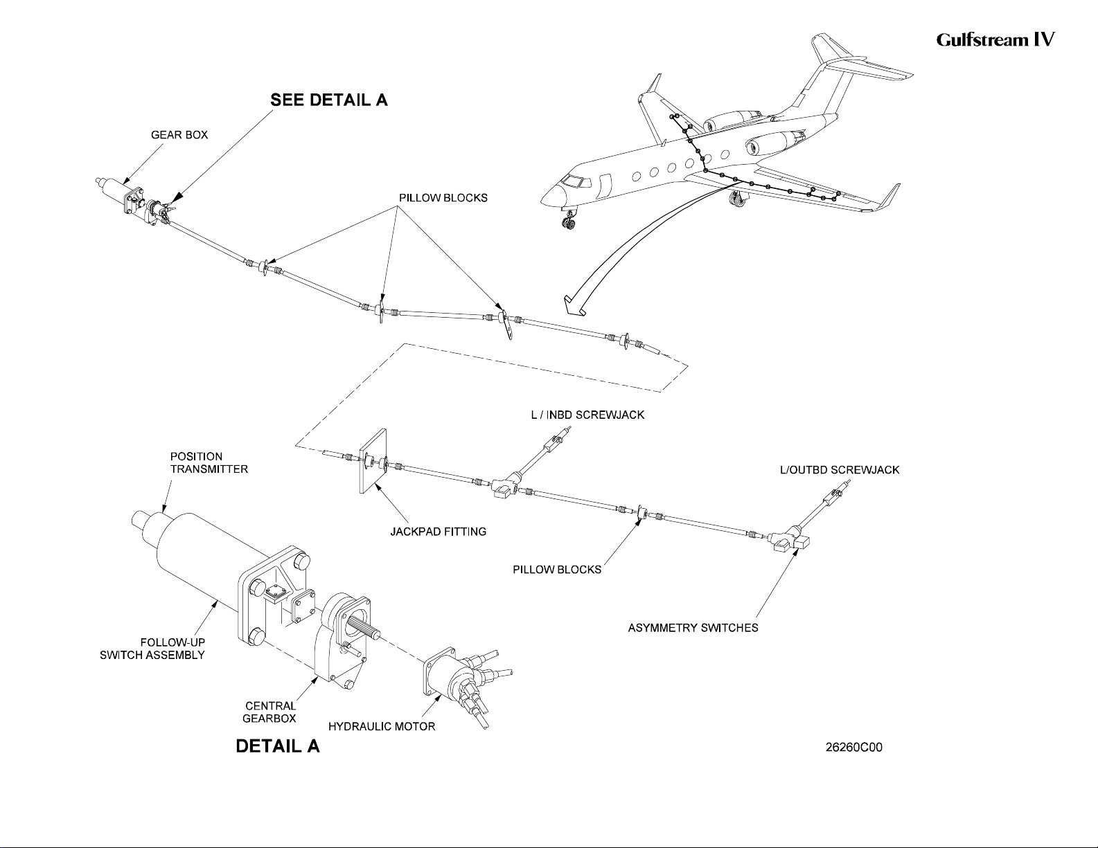
OPERATING MANUAL
Flaps Simplified Block
Diagram
Figure 18
2A-27-00
Page 61 / 62
January 31/02
Page 51
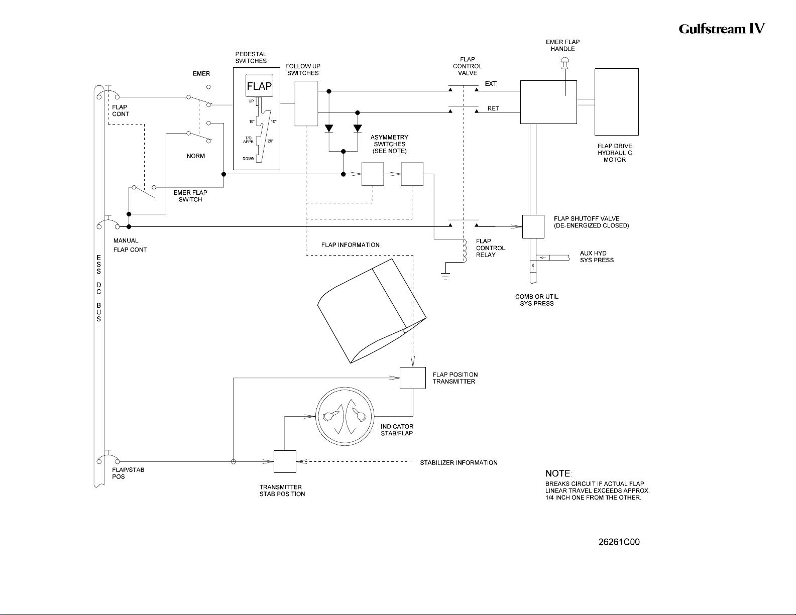
OPERATING MANUAL
Flaps Simplified Electrical
Diagram
Figure 19
2A-27-00
Page 63 / 64
January 31/02
Page 52
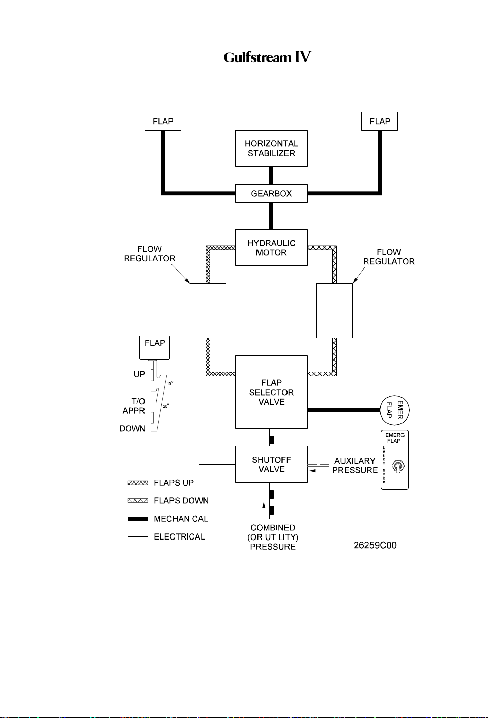
OPERATING MANUAL
Flaps / Horizontal Stabilizer System Hydraulic Control Diagram
Figure 20
PRODUCTION AIRCRAFT SYSTEMS 2A-27-00
Page 65
January 31/02
Revision 6
Page 53
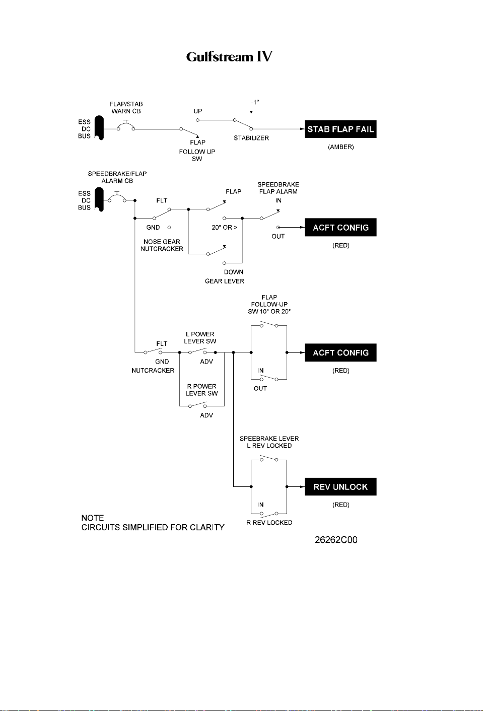
OPERATING MANUAL
Page 66
January 31/02
Configuration Warning System Simplified Electrical Diagram
Figure 21
PRODUCTION AIRCRAFT SYSTEMS2A-27-00
Revision 6
Page 54
OPERATING MANUAL
2A-27-70: Spoiler System
1. General Description:
The spoiler system for the Gulfstream IV assists the flight crew in maintaining roll
control of the aircraft, functioning as flight spoilers. Additionally, while in flight, the
spoilers extend to decrease airspeed and increase descent rate, functioning as
speed brakes. On the ground after landing, they function as ground spoilers,
extending to help dump any remaining lift and increase braking effectiveness.
The aircraft has three spoilers on the upper trailing edge of each wing (from
inboard to outboard): a ground spoiler, an inboard flight spoiler and an outboard
flight spoiler. The spoilers are manually and electrically controlled, hydraulically
powered, and mechanically actuated. They are hinged to open forward when
extended and close aft when retracted. Four hydraulic actuators convert hydraulic
pressure to a linear mechanical force to position the spoilers.
Spoiler panel function and position depends upon the control input. Moving the
SPEED BRAKE handle to the extend position extends all six spoiler panels
simultaneously to function as speed brakes. Rotating the control wheel from the
neutral position extends the inboard and outboard spoiler panels on the same
wing as the raised aileron, functioning as flight spoilers to assist with roll control.
When armed, all six spoiler panels extend automatically extend on touchdown to
dump lift and increase braking effectiveness, functioning as ground spoilers.
Panel function and position is summarized in the following table:
INPUT CONDITION PANEL POSITION
Maximum Aileron, No Speed Brakes Two Down-Wing Flight Spoilers Extended
Maximum Speed Brakes, No Aileron All Six Panels Extended 26°
Maximum Speed Brakes, Maximum
Aileron
Automatic Ground Spoilers All Panels Extended 55°
The spoiler system is composed of the following subsystems, units and
components:
• Flight Spoiler System
• Speed Brake System
• Ground Spoiler System
• Flight Power Shutoff System
2. Description of Subsystems, Units and Components:
A. Flight Spoiler System:
(See Figure 25.)
Flight spoilers are incorporated into the roll flight control system to improve
aircraft roll response. Spoiler travel varies in proportion to the degree of roll
input. The flight spoiler system is solely a hydraulically powered system,
thus reversion to manual control is not possible.
As the aileron control system commands an aileron to deflect upward, a
mixing linkage between the aileron and flight spoiler control systems
transmits an extend command to the flight spoiler actuator servo control
valve. The servo control valve then shifts to direct pressure to the flight
23°, All Other Panels Retracted
Two Down-Wing Flight Spoilers Extended
55°, Two Ground Spoilers Extended 26°,
Two Up-Wing Flight Spoilers Extended
26°,
PRODUCTION AIRCRAFT SYSTEMS 2A-27-00
Page 67
January 31/02
Revision 6
Page 55

OPERATING MANUAL
spoiler actuator. This allows the two outboard spoiler panels on the same
side as the raised aileron to extend commensurate with the amount of roll
input, up to a maximum of 23 ±2°. The opposite spoilers remain flush to the
wing as that aileron travels downward.
If the speed brakes are extended, the flight spoilers may extend up to a
maximum of 55 +4/-3°. The opposite spoilers remain in the position
commanded as speed brakes.
B. Speed Brake System:
(See Figure 23 and Figure 25.)
The speed brake system provides a method for manual symmetrical
deployment of all six spoiler panels in flight to decrease airspeed and
increase descent rate. They may also be manually extended on the ground
to increase braking effectiveness, should the ground spoilers not
automatically extend upon landing or an aborted takeoff. This is
accomplished by mechanical control of the left and right flight spoiler
actuators through the use of the SPEED BRAKE handle located on the
cockpit center pedestal. The speed brake system is solely a hydraulically
powered system, thus reversion to manual control is not possible.
Moving the SPEED BRAKE handle out of the RETRACT detent provides
simultaneous mechanical input to the left and right flight spoiler mixing
linkages. Each mixing linkage then shifts the associated flight spoiler
actuator servo control valve to the extend position. The servo control valve
then directs Combined and Flight hydraulic system pressure to the actuator
piston. The pistons extends and the attached mechanical linkage drives all
six spoiler panels to a position commensurate with SPEED BRAKE handle
position. Speed brake position is infinitely variable between fully retracted
(0°) and fully extended (26 ±2°), depending on handle position.
With speed brakes extended, rotation of the control wheel repositions the
mechanical linkage between the aileron and flight spoiler control
mechanisms. Movement in either direction will further extend the outboard
two (inboard and outboard flight spoiler) panels on the side of the raised
aileron, up to a maximum of 55 +4/-3°. These panels will return to their
original speed-brakes-extended position when the control wheel is returned
to neutral.
When speed brakes are extended, a blue SPD BRAKE EXTNDED
advisory message is displayed on the Crew Alerting System (CAS). In
addition, the SPEED BRAKE handle will illuminate blue.
Should the fault warning computer and flight guidance computer disagree
on the position of the speed brakes, a blue SPD BRAKE SWITCH advisory
message is displayed on CAS.
A red ACFT CONFIGURATION warning message will be displayed on
CAS, along with the associated warning tone, whenever the SPEED
BRAKE handle is not in the RETRACT detent and the following conditions
occur:
• Advancing either power lever above 80% HP RPM on the ground
• Extending the flaps to DOWN (39°) or extending the landing gear in
flight
For aircraft having a Standby Warning Lights Panel (SWLP) installed, a red
ACFT CONFIG light will be illuminated whenever the SPEED BRAKE
Page 68
January 31/02
PRODUCTION AIRCRAFT SYSTEMS2A-27-00
Revision 6
Page 56

OPERATING MANUAL
handle is not in the RETRACT detent and the following conditions occur:
• Advancing either power lever above the takeoff power range on the
ground
• Extending the flaps past 22° or extending the landing gear in flight
C. Ground Spoiler System:
(See Figure 22 through Figure 24.)
(1) General:
The ground spoiler system provides the capability for full and
automatic deployment of all six spoiler panels upon aircraft
touchdown in order to dump any remaining lift and increase braking
effectiveness. Also, if takeoff is aborted, the system provides for
automatic deployment of all spoiler panels.
The inboard spoilers on each wing are used as ground spoilers and,
through electrical control, are powered by the Combined or Flight
hydraulic system. Ground spoiler operation is dependent on control
signal pressure being available from the Combined, Utility or
Auxiliary hydraulic system. When the system is armed (GND SPLR
switch selected to ARMED), the ground spoilers extend to 55 +4/-3°
upon touchdown as the power levers are retarded to the ground idle
setting. Movement of the two ground spoiler actuators provides an
input to the two flight spoiler actuators, causing flight spoiler
extension to 55 +4/-3°. These two actions result in all six panels
extending. After rollout is completed, all six spoiler panels are
retracted by selection of the GND SPLR switch to OFF. Switch
selection to OFF also causes a blue GND SPOILER UNARM
advisory message to be displayed on CAS.
NOTE:
The GND SPLR switch is normally selected to ARMED
on lineup before takeoff. If either power lever is
advanced above idle after the spoilers are armed, the
electrical circuit to the primary and secondary
solenoid-operated hydraulic control valves is broken.
The spoilers will remain stowed even though the GND
SPLR switch is selected to ARMED.
If the aircraft is operating on Essential DC bus power only, the
ground spoilers are inoperative, as power for the system is required
from the Main DC bus. If Main DC bus power is not available and the
GND SPLR switch is selected to ARMED, a red NO GND
SPOILERS warning light (windshield center post) illuminates when
the power levers are retarded to ground idle after landing. Since the
ground spoilers are inoperative, no input is made to the flight
spoilers, thus they also do not extend. In this case, the speed brakes
would be extended at the discretion of the flight crew.
The ground spoiler system incorporates two distinct warning
functions. The first warning function occurs only on the ground, and
is activated if the ground/flight spoilers do not automatically extend
upon touchdown. This is annunciated by illumination of the red NO
GND SPOILERS warning light on the windshield center post. The
PRODUCTION AIRCRAFT SYSTEMS 2A-27-00
Page 69
January 31/02
Revision 6
Page 57

OPERATING MANUAL
second warning function can occur both on the ground and in flight,
and is activated if there is a failure within the ground spoiler system
which might result in inadvertent spoiler extension. This is
annunciated by a red GND SPOILER warning message displayed
on CAS and, if installed, the SWLP.
(2) Hydraulic Operation:
The ground spoiler system requires both control pressure and
operating pressure. Control pressure, also known as servo
pressure, is normally supplied by the Combined hydraulic system,
but can be supplied by either the Utility or Auxiliary hydraulic
systems. Operating pressure is supplied by the Combined and
Flight hydraulic systems. The ground spoiler system is solely a
hydraulically powered system, thus reversion to manual control is
not possible.
The ground spoiler hydraulic system contains primary and
secondary solenoid-operated hydraulic control valves located in the
main wheel well. Two ground spoiler actuators (one per side) are
located at the inboard ends of the left and right wing rear beam.
During normal operation, Combined and Flight hydraulic system
pressure is supplied through the open flight power shutoff valve to
the retract side of the ground spoiler actuators.
The ground spoiler automatic deployment feature is accomplished
by a common hydraulic signal that overrides any input to the servo
valve through the SPEED BRAKE handle. The override signal is
supplied by Combined (or Utility or Auxiliary) hydraulic pressure to
both actuators through normally-closed solenoid valves. Since the
override signal is common to both the left and right actuators, the
possibility of asymmetrical extension is virtually eliminated.
In the unlikely event that the ground spoilers inadvertently extend
during low-speed flight, the ground spoiler control system will extend
all six spoiler panels in unison to 55 +4/-3°. Should this occur at
higher airspeeds, the panels will “blow back” to an angle that
balances the aerodynamic load against the panels with the force
applied by the actuators.
If both Combined and Flight hydraulic system pressure is lost, a
bypass feature in the actuators allows the spoiler panels to “blow
down” to a trail position.
(3) Operational Logic:
The ground spoiler control system will automatically extend all six
spoiler panels in unison to 55 +4/-3° when the following parameters
are satisfied:
• Main DC bus power is available to provide electrical power
for the system
• Combined (or Utility or Auxiliary) hydraulic pressure is
available to provide servo pressure for spoiler control
• Combined or Flight hydraulic pressure is available to provide
operational pressure to extend the spoilers
• GND SPLR switch is selected to ARMED
Page 70
January 31/02
PRODUCTION AIRCRAFT SYSTEMS2A-27-00
Revision 6
Page 58

OPERATING MANUAL
• Both power levers are retarded to ground idle
• Main landing gear Weight-On-Wheels (WOW) is sensed by
the nutcracker system
• At wheel spinup greater than 57 knots (48 knots for aircraft
with ASC 307 incorporated) when:
• Flaps position is greater than 22° OR:
• Flaps position is less than 22° and the GND SPLR
FLAP ORIDE switch is selected to ON
(4) Ground Spoiler Warning System:
The ground spoiler system is monitored by a warning circuit that will
detect certain in-flight and on-ground malfunctions within the ground
spoiler system.
(a) A red GND SPOILER warning message will be displayed on
CAS and, if installed, the SWLP, should any of the following
events occur while in flight:
• One or both ground spoilers not fully retracted with
SPEED BRAKE handle in RETRACT detent
• Primary solenoid-operated hydraulic control valve
failure with secondary solenoid-operated hydraulic
control valve pressurized
• Secondary solenoid-operated hydraulic control valve
electrically energized
• Failure of the primary solenoid-operated hydraulic
control valve nutcracker relay No. 6
• Failure of the secondary solenoid-operated hydraulic
control valve nutcracker relay No. 1
Additionally,the red GND SPOILER warning message will be
displayed should any of the following events occur while on
the ground:
• Primary solenoid-operated hydraulic control valve
failure with the power levers not in ground idle
• Unlocked ground spoiler with power levers at takeoff
power
(b) A red NO GND SPOILERS warning light, located adjacent to
the pilot’s AOA indexer on the windshield center post, will
illuminate if the ground spoilers do not automatically extend
upon touchdown.
(5) Ground Spoiler System Check:
The following ground spoiler system check should be performed
during the After Starting Engines checklist prior to the first departure
of each day. It provides a complete functional check of the automatic
ground spoiler system and ground spoiler warning system.
(a) Verify the GND SPLR switch is selected to OFF.
(b) Verify left and right power levers are positioned to idle. Verify
the following indications:
• Ground spoilers are stowed (visually check)
PRODUCTION AIRCRAFT SYSTEMS 2A-27-00
Page 71
January 31/02
Revision 6
Page 59

OPERATING MANUAL
• NO GND SPOILERS light is extinguished
• GND SPOILER warning message is not displayed on
CAS
• GND SPOILER UNARM advisory message is
displayed on CAS
(c) Select the GND SPLR switch to ARMED. Verify the following
indications:
• Ground spoilers are extended (visually check)
• NO GND SPOILERS light is extinguished (may flash
momentarily)
• GND SPOILER warning message is not displayed on
CAS
• GND SPOILER UNARM advisory message is not
displayed on CAS
(d) Advance the left power lever out of idle. (See Note 1.) Verify
the following indications:
• Ground spoilers are stowed (visually check)
• NO GND SPOILERS light is extinguished
• GND SPOILER warning message is not displayed on
CAS (may appear momentarily)
(e) Advance the right power lever out of idle.
(f) Retard the left power lever to idle. Verify the following
indications:
• Ground spoilers remain stowed (visually check)
• NO GND SPOILERS light is extinguished
• GND SPOILER warning message is not displayed on
CAS
(g) Select the GND SPLR switch to OFF. Verify the following
indications:
• GND SPOILER UNARM advisory message is
displayed on CAS
(h) Press and hold the GND SPLR TEST switch. (See Notes 2
and 3.) Verify the following indications:
• Ground spoilers remain stowed (visually check)
• NO GND SPOILERS light is illuminated
• GND SPOILER warning message is displayed on CAS
• Both MASTER WARN lights illuminate
• GND SPOILER UNARM advisory message is
displayed on CAS
• GND SPOILER light on SWLP (if installed) is
illuminated
(i) Release the GND SPLR TEST switch. Verify the following
indications:
• Ground spoilers remain stowed (visually check)
Page 72
January 31/02
PRODUCTION AIRCRAFT SYSTEMS2A-27-00
Revision 6
Page 60

OPERATING MANUAL
• NO GND SPOILERS light is extinguished
• GND SPOILER warning message is not displayed on
CAS
• Both MASTER WARN lights are extinguished
• GND SPOILER UNARM advisory message is
displayed on CAS
• GND SPOILER light on SWLP (if installed) is
extinguished
(j) Retard the right power lever to idle. Verify the following
indications:
• NO GND SPOILERS light is extinguished
• GND SPOILER warning message is not displayed on
CAS
• GND SPOILER UNARM advisory message is
displayed on CAS
NOTE:
(1) When the power lever is advanced, the red GND
SPOILER warning message may be displayed
momentarily and then extinguish. If the message
remains extinguished, continue the test.
(2) The absence of either the NO GND SPOILERS
light or the GND SPOILER message during Step 6 of
the ground spoiler system check, or any incorrect
indication, constitutes an unsuccessful ground spoiler
system check.
(3) The ground spoilers cannot always be observed
from the cockpit. The correct GND SPOILER message
and NO GND SPOILERS light indications are
sufficient for satisfactory preflight functional
verification.
D. Flight Power Shutoff System:
The flight power shutoff valve is a mechanically operated shutoff valve
located between the Combined and Flight hydraulic system pressure
sources and the flight and ground spoiler actuator pressure lines. The
valve consists of two mechanically connected but hydraulically isolated
sections.A controlex cable connects the valve to a FLIGHT POWER SHUT
OFF handle located on the left aft side of the cockpit center pedestal. See
Figure 8.
Moving the FLIGHT POWER SHUT OFF handle up from its stowed
(horizontal) position to the vertical position mechanically closes the flight
power shutoff valve. With the valve closed, operating pressure is removed
from the spoiler actuators and use of the system is not possible.
In accordance with limitations established in the GIV Airplane Flight
Manual, pulling the FLIGHT POWER SHUTOFF handle with speed brakes
PRODUCTION AIRCRAFT SYSTEMS 2A-27-00
Page 73
January 31/02
Revision 6
Page 61
OPERATING MANUAL
extended is prohibited.
The resultant advantage of the flight power shutoff provision is the ability to
bypass a malfunctioning actuator (such as would be the need in the
unlikely event of an actuator jam) and manually fly the aircraft. Although
control column effort and response time to inputs are increased while in
manual reversion, the aircraft remains capable of positive and harmonious
control.
3. Controls and Indications:
(See Figure 23 and Figure 24.)
A. Circuit Breakers (CBs):
Circuit Breaker Name: CB Panel: Location: Power Source:
GND SPOILER CPO C-6 Left Main DC Bus
SPD BRAKE/FLAP ALARM P D-4 Essential DC Bus
B. Warning (Red) Messages and Annunciations:
CAS Message: SWLP Indication Cause or Meaning:
ACFT
CONFIGURATION
ACFT CONFIG Position of one or more of the
following controls is not correct:
• FLAP Handle
• SPEED BRAKE Handle
• Landing Gear Control Handle
GND SPOILER GND SPOILER Failure of ground spoiler
component or deployed ground
spoiler panel.
Annunciation: Cause or Meaning:
Red NO GND SPOILERS light on
windshield center post.
Failure of ground spoiler component or
deployed ground spoiler panel.
C. Advisory (Blue) Messages and Annunciations:
CAS Message: Cause or Meaning:
GND SPOILER
UNARM
SPD BRAKE
EXTNDED
Ground spoiler system is not armed.
Speed brakes are extended.
SPD BRAKE SWITCH FWC and FGC disagree on position of speed brakes.
Annunciation: Cause or Meaning:
SPEED BRAKE handle illuminated (pale
blue).
SPEED BRAKE handle not in RETRACT
detent.
4. Limitations:
A. Flight Manual Limitations:
(1) Use of Speed Brakes:
Speed brakes are not approved for extension with flaps at 39°
(DOWN) or with landing gear extended in flight.
(2) Use of FLIGHT POWER SHUTOFF:
Do NOT pull FLIGHT POWER SHUTOFF handle with speed brakes
extended.
PRODUCTION AIRCRAFT SYSTEMS2A-27-00
Page 74
January 31/02
Revision 6
Page 62

OPERATING MANUAL
(3) Automatic Ground Spoilers:
Takeoff is permitted with automatic ground spoilers inoperative,
provided anti-skid is operative and 20° flaps are used for takeoff.
When the Standby Electrical System is in operation, the following
limitations also apply:
(4) Use of Speed Brakes:
Speed brakes may be used, however, operation should be slow
(approximately five [5] seconds for full range movement).
(5) Landing with Standby Electrical System Operating:
Landing is approved provided automatic ground spoilers and thrust
reversers are not used for landing. See Section 05-17-50, Landing
With Standby Electrical Power System Operating.
B. Other Operational Information:
(1) Speed Brake Operating Envelope:
Speed brake operation is permitted within the flight envelope up to
and including V
MO/MMO.
(2) Speed Brake Operating Altitude:
The use of speed brakes at altitudes below 2,000 feet AGL is not
recommended.
(3) Effects of Speed Brake Operation:
A mild nose-up trim change and some buffet may be expected when
speed brakes are fully extended. For passenger comfort, it is
recommended that speed brakes be extended and retracted slowly,
retrimming as required.
PRODUCTION AIRCRAFT SYSTEMS 2A-27-00
Page 75
January 31/02
Revision 6
Page 63

OPERATING MANUAL
THIS PAGE IS INTENTIONALLY LEFT BLANK.
Page 76
January 31/02
PRODUCTION AIRCRAFT SYSTEMS2A-27-00
Page 64
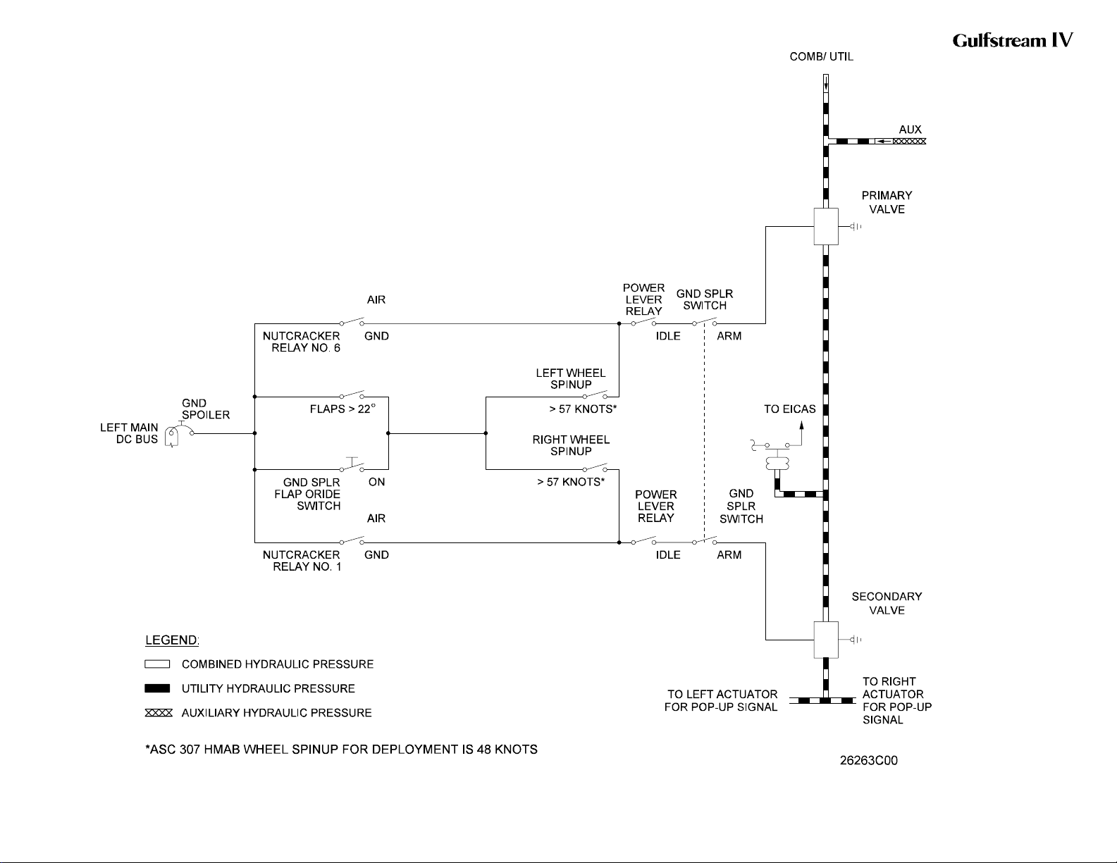
OPERATING MANUAL
Spoiler Control System
Simplified Electrical
Diagram
Figure 22
2A-27-00
Page 77 / 78
January 31/02
Page 65
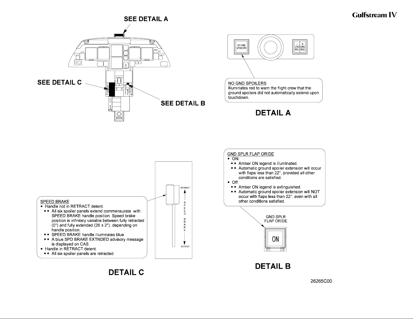
OPERATING MANUAL
Spoiler/Speed Brake
Controls and Indications
Figure 23
2A-27-00
Page 79 / 80
January 31/02
Page 66
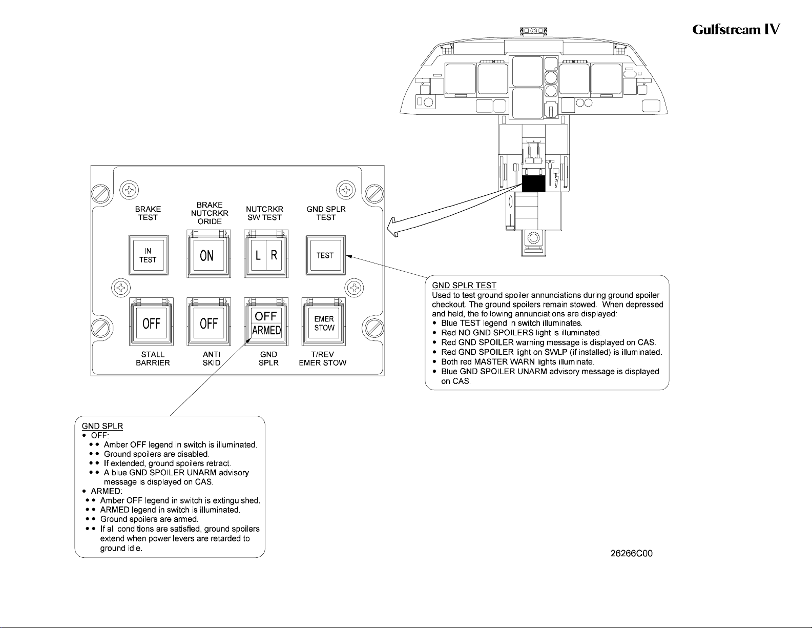
OPERATING MANUAL
Ground Spoiler Controls
and Indications
Figure 24
2A-27-00
Page 81 / 82
January 31/02
Page 67
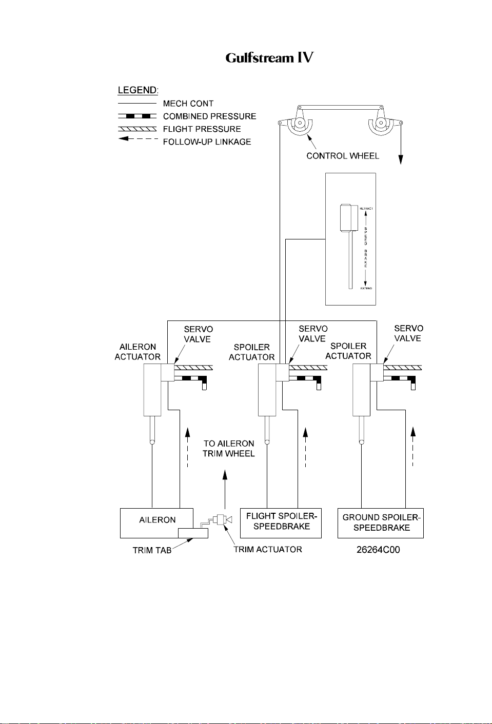
OPERATING MANUAL
Spoiler/Speed Brake Control System Simplified Block Diagram
Figure 25
PRODUCTION AIRCRAFT SYSTEMS 2A-27-00
Page 83
January 31/02
Revision 6
Page 68

OPERATING MANUAL
2A-27-80: Gust Lock System
1. General Description:
The gust lock system for the Gulfstream IV provides a means for the flight crew to
manually protect the unpowered flight control surfaces from movement by wind
gusts while the aircraft is on the ground.
The gust lock is a mechanical ground safety system that neither affects the flight
performance of the aircraft nor receives any flight loads. The ailerons, elevators
and rudder are locked against gust loads by mechanical latches operated by the
GUST LOCK handle located on the cockpit center pedestal.
2. Description of Subsystems, Units and Components:
A. Surface Lock System:
(See Figure 26.)
A single T-shaped handle, located on the right side of the cockpit center
pedestal and labeled GUST LOCK, controls the gust lock system. A spring
loaded trigger is incorporated in the gust lock handle to prevent the handle
from inadvertently being pulled. Releasing the trigger and then raising and
pulling the GUST LOCK handle aft actuates conventional mechanical
linkage consisting of cables, springs, latches and a bungee rod. Moving the
ailerons and rudder to the neutral position and the elevator to the trailing
edge down position allows the gust lock to engage and lock the flight
controls as their linkages reach the locking position. Releasing the trigger
and then lowering the GUST LOCK handle releases the gust lock.
Safety features prevent the gust lock from inadvertently engaging or a
failure of the system preventing gust lock release. With the gust lock
released, the bungee rod acts as a fixed rod to prevent inadvertent flight
control locking. If the gust lock fails when engaged, the springs will unlock
the gust lock.
B. Mechanical Power Lever Interlock:
A mechanical interlock is incorporated in the GUST LOCK handle
mechanism that restricts simultaneous movement of the power levers to a
maximum of six percent above ground idle with the gust lock engaged.
Force applied to advance both power levers simultaneously cannot
override the interlock. To prevent any hydraulic forces acting upon an
engaged gust lock, the gust lock should be released prior to engine starting
and not engaged until all hydraulic pressures read zero.
3. Controls and Indications:
(See Figure 26.)
4. Limitations:
A. Flight Manual Limitations:
There are no limitations for the gust lock system at the time of this revision.
Page 84
January 31/02
PRODUCTION AIRCRAFT SYSTEMS2A-27-00
Revision 6
Page 69

OPERATING MANUAL
B. Other Operational Limitations:
The gust lock is effective in protecting the flight controls in wind gusts up to
60 knots.
CAUTION
ENSURE HYDRAULIC PRESSURE IS DEPLETED
PRIOR TO ENGAGING GUST LOCK. CYCLE THE
CONTROLS WITH THE CONTROL COLUMN,
CONTROL WHEEL AND RUDDER PEDALS TO
DEPLETE ANY RESIDUAL PRESSURE.
PRODUCTION AIRCRAFT SYSTEMS 2A-27-00
Page 85
January 31/02
Revision 6
Page 70
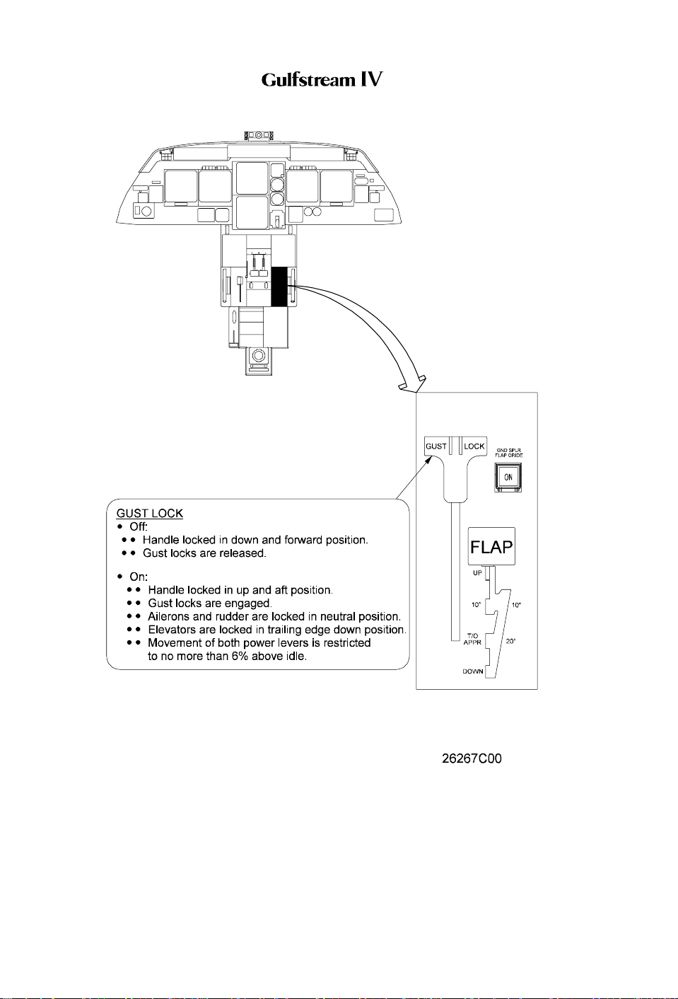
OPERATING MANUAL
Page 86
January 31/02
GUST LOCK Handle
Figure 26
PRODUCTION AIRCRAFT SYSTEMS2A-27-00
Revision 6
 Loading...