

Page 1

OPERATING MANUAL
Title Page
Prev Page
Next Page
TOC
FLIGHT CONTROLS
2A-27-10: General
1. General Description:
The aircraft flight controls allow the flight crew to guide the aircraft in the
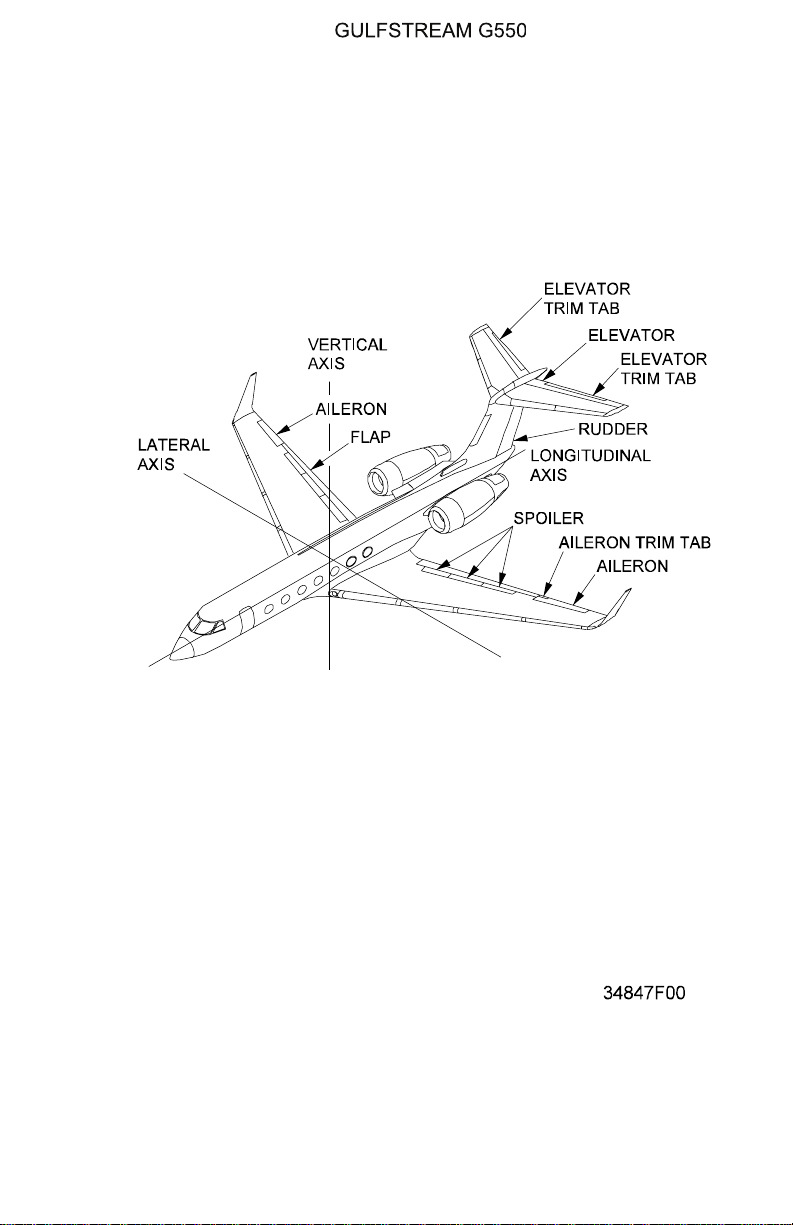
longitudinal, vertical and horizontal axes (see Figure 2). The primary flight controls
are:
• Elevator to control aircraft pitch
• Rudder to control aircraft yaw
• Aileron to control aircraft roll
The primary flight controls are positioned by moving the pilot and copilot control
yokes and rudder pedals. Both yokes are mechanically linked together so that
either crew position has full control authority and control inputs are transparent to
both crew members since movement of one set of controls will move the
corresponding set of controls. Each yoke has a dedicated cable connection to the
elevator and aileron control on that respective side, but since the yokes are
mechanically linked, moving one side elevator or aileron will move the flight
controls on both sides. For instance, the copilot yoke is cable-linked to the right
elevator and the right aileron but any movement of the copilot yoke also moves
the pilot yoke that is in turn cable-linked to the left aileron and left elevator. This
system of split control authority and linked yoke movement provides a means to
maintain some flight control movement if one of the flight controls or associated
linkages becomes jammed. If a malfunction prevents movement of either the
elevators or ailerons, the mechanical links joining the two pilot yokes can be
severed, thereby allowing movement of the left or right elevator or aileron that
remains operational by commands using the yoke connected to the side of the
free control surface.
The two sets of rudder pedals are similarly mechanically linked together, but both
are connected to the rudder by a single cable. For this reason, there is no
provision for interrupting the linkage between the two sets of pedals, since each
set does not have an independent route to the rudder.
The cable connections from the yokes and rudder pedals are continuous loop
installations, providing feedback to the moveable controls. The control cables
engage bell cranks that translate cable movement into displacement commands
for hydraulic actuators that boost contol inputs to move the flight controls. Each
hydraulic actuator has a single shaft, but dual piston chambers in order that the
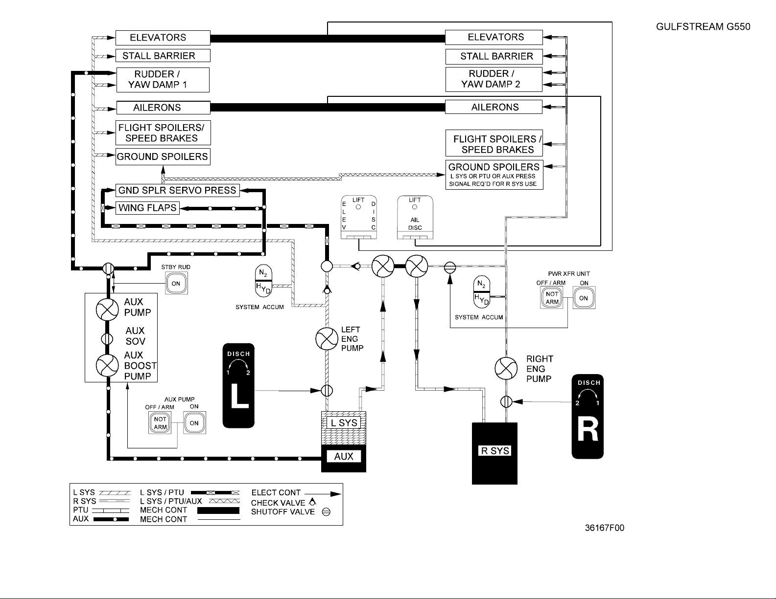
actuator may be driven by both (or either) left and right hydraulic system. (The
hydraulic system power sources for the flight controls are shown in Figure 1.) The
rudder actuator may also be powered by the Auxiliary (AUX) hydraulic system in
the event of dual hydraulic power failure. Each of the hydraulic actuators is
connected to the associated flight control by pushrods and bell cranks to impart
mechanical movement to the control surface. A bungee piston filled with hydraulic
fluid moderates the rate of actuation of the flight control and provides an artificial
feel input to the flight crew through the closed loop cable system. The failure of a
single hydraulic system does not degrade flight control operation - the remaining
system provides adequate power for flight control movement, and the actuator
chamber for the failed system bypasses fluid so there is no resistance to flow. If
both (or all, in the case of the rudder) hydraulic systems fail, both actuator
chambers bypass fluid, and pilot input through the cable connection moves the
PRODUCTION AIRCRAFT SYSTEMS 2A-27-00
Page 1
August 14/03
Page 2

OPERATING MANUAL
Title Page
Prev Page
Next Page
TOC
internal shaft of the actuator and the associated pushrods and bellcranks without
powered assistance. More pilot force is required, but full movement of the flight
controls is attainable.
The autopilot is interfaced with the primary flight controls through electric servos
to move parallel cable linkages to the hydraulic actuators. Each flight control
surface has a Linear Variable Displacement Transducer (LVDT) that provides an
electrical signal proportional to flight control surface displacement from neutral.
The LVDT signal provides feedback to the autopilot for positioning the flight
controls, and also communicates control surface position for display on systems
and synoptic windows through interface with the Modular Avionics Units (MAUs).
The description of the Digital Automatic Flight Control Systems (autopilot) makes
up the entire content of Section 2B of this manual, and for that reason is not
covered in this Section. However, for the convenience of the reader, a tabulation
of the Crew Alerting System (CAS) messages associated with the autopilot is
included below.
The elevators and ailerons have trim tabs to position the flight controls with
aerodynamic forces to moderate the amount of physical effort to maintain the
control surfaces in the desired steady-state condition. The rudder is not equipped
with a trim tab, but instead has a mechanical trim input to reset the neutral
position of the rudder. The mechanical trim uses the hydraulic actuator to project
the rudder slightly into the windstream in the desired direction to compensate for
induced yaw.
The secondary flight controls and functions are:
• Wing flaps - enhance wing lift characteristics
• Flight and Ground Spoilers - reduce wing lift and add overall drag
• Movable horizontal stabilizer - aligns the elevator with aircraft angle of
attack
• Yawdamper - uses the autopilot rudder servo to moderate aircraft heading
oscillation
Some functions of the secondary flight controls are integrated with the operation
of the primary flight controls and other functions mutually complement the
operation of other secondary controls.
• As flaps extend, moving the wing center of lift aft, a downward pitch
moment is created - the moveable stabilizer automatically compensates for
the pitch moment by trimming downward. The opposite movement occurs
as flaps are retracted and the nose of the aircraft pitches up.
• When ailerons are used, flight spoilers on the downward wing activate to
increase roll rate and provide yaw into the turn. Ground spoilers decrease
ground roll distance during landings and aborted takeoffs.
• The yaw damper provides a degree of turn coordination for aileron roll
commands, provided wing flaps are not selected to more than thirty
degrees (30°).
Safety features incorporated into the flight controls system include:
• A stick shaker warning and a stick pusher stall prevention actuator.
• A gust lock that prevents damage to flight controls while the aircraft is
secured on the ground.
Page 2
August 14/03
PRODUCTION AIRCRAFT SYSTEMS2A-27-00
Page 3
OPERATING MANUAL
Title Page
Prev Page
Next Page
TOC
2. Primary and Secondary Flight Controls Subsections:
The primary and secondary flight controls are discussed in the following
subsections:
• 2A-27-20: Elevator Pitch Control
• 2A-27-30: Rudder Yaw Control
• 2A-27-40: Aileron Roll Control
• 2A-27-50: Horizontal Stabilizer and Wing Flaps
• 2A-27-60: Stall Warning and Prevention System
• 2A-27-70: Speed Brake and Ground Spoilers
• 2A-27-80: Flight Controls Gust Lock
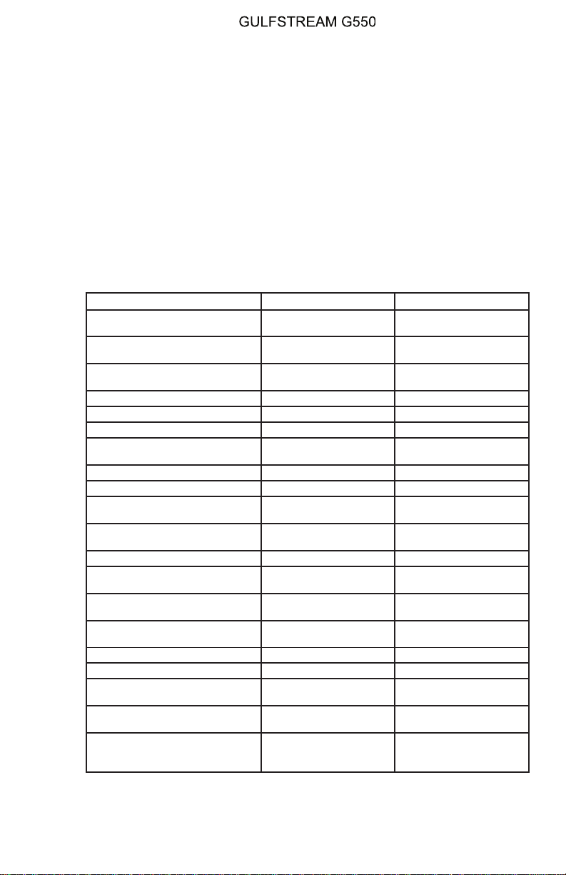
3. Autopilot Crew Alerting System (CAS) Messages:
The following CAS messages are associated with the operation of the autopilot
and integrated subsystems:
Area Monitored: CAS Message: Message Color:
Flight Guidance Computer
Internal Monitor
Flight Guidance Panel AP
Engage Switch
AP Engage Switches AP Engage Inhibit -Sw
AP 1-2 Fail Amber
AP Control Switch
Stuck
Active
Blue
Blue
Air Data System AP Inhibit - ADS Blue
Inertial Reference System AP Inhibit - IRS Blue
Control Column Force AP Inhibit - Left Column Blue
Control Column Force AP Inhibit - Right
Column
Blue
Control Wheel Force AP Inhibit - Left Wheel Blue
Control Wheel Force AP Inhibit - Right Wheel Blue
Manual Trim Wheel AP Inhibit - Man Trim
Autopilot Quick Disconnect
Switch
Active
AP Inhibit - QD Blue
Blue
Stall Shaker AP Inhibit - Stall Blue
Autopilot Touch Control
Steering Switch
Control Wheel Electric Trim
Switch
Weight On Wheels (WOW)
System
AP Inhibit - TCS Blue
AP Inhibit -Trim Cmd Blue
AP Inhibit - WOW Blue
Autopilot Power Source AP 1-2 Power Fail Blue
Autopilot Elevator Trim Servo AP / Trim Fail Blue
Flight Guidance Panel Speed
Window
Flight Guidance Computer /
WOW System
Take Off and Go Around
(TOGA) Engage Switch / Flight
Guidance Panel Manual Speed
Check Speed Target Blue
FGC - WOW Fault Blue
Go Around Pitch Blue
PRODUCTION AIRCRAFT SYSTEMS 2A-27-00
Page 3
August 14/03
Page 4

OPERATING MANUAL
Title Page
Prev Page
Next Page
TOC
THIS PAGE IS INTENTIONALLY LEFT BLANK.
Page 4
August 14/03
PRODUCTION AIRCRAFT SYSTEMS2A-27-00
Page 5
OPERATING MANUAL
Title Page
Prev Page
Next Page
TOC
Flight Controls System:
Simplified Fluid Power
Diagram
Figure 1
2A-27-00
Page 5 / 6
August 14/03
Page 6

Title Page
Prev Page
Next Page
TOC
Page 7
OPERATING MANUAL
Title Page
Prev Page
Next Page
TOC
Flight Controls System Components
Figure 2
PRODUCTION AIRCRAFT SYSTEMS 2A-27-00
Page 7
August 14/03
Page 8

OPERATING MANUAL
Title Page
Prev Page
Next Page
TOC
2A-27-20: Elevator Pitch Control
1. General Description:
The aircraft has a dual elevator installation to control aircraft pitch attitude. The
elevators are composed of a baked graphite-epoxy material. Each of the cockpit
yokes is connected to one of the aircraft elevators. The pilot yoke is connected to
the left elevator,the copilot yoke to the right elevator.Eachyokeisalsoconnected
to the other by a mechanical torque tube beneath the cockpit floor. Since both
yokes are interconnected, moving one yoke moves both elevators.
Braided steel cables run from each yoke to hydraulic assist actuators in the tail of
the aircraft. The cables are routed beneath the aircraft floor using pulley
connections to clear other installed equipment. The cables mate with the hydraulic
assist actuators via bellcranks that translate pulley rotational motion into forward
and aft motion. The actuators each have a single shaft powered by two piston
chambers, one chamber for each (left and right) hydraulic system. Both hydraulic
systems normally power the actuators, but one system is sufficient for full elevator
movement. The actuators are connected to the respective elevator by linkages
and bellcranks, moving the elevator up or down about the pivot points on the aft of
the horizontal stabilizer. The deflection range of the elevators is twenty-four
degrees (24°) up and thirteen degrees (13°) down.
Each connection of yoke to elevator is a continuous loop. Incorporated into the
loops adjacent to the actuators is a bungee cylinder filled with viscous fluid to
resist yoke / elevator movement in order to provide artificial feel to each yoke.
Each elevator also has a stability spring incorporated into the cable linkage to
provide a forward pull to the control yoke and to contribute additional feel input.
Both sides of the hydraulic actuators are monitored to assure correct operation.
The cockpit cable input motion must result in a corresponding actuator output
motion, and similarly the output side of the actuator should not move without
cockpit input. If input and output do not correspond, actuator hydraulic pressure is
bypassed to prevent movement of the elevator.
Anytime hydraulic pressure to the actuators is bypassed or lost (in the instance of
dual hydraulic system failure) the elevators remain operable with manual yoke
movement that positions the actuator shaft and connecting linkages to the
elevator. Control forces will be higher, since normal hydraulic assist provides a six
(6) to one (1) boost advantage to move the elevator surfaces.
Each elevator is equipped with a trim tab that uses aerodynamic pressure to aid in
positioning the control surface. The trim tabs are controlled manually by rotating a
wheel on the cockpit pedestal or electrically using switches on the control yokes.
Manual trim uses a dedicated braided wire connection from the cockpit to a
mechanical linkage in the tail. Electrical switch trim movement commands an
electric servo to move the same linkage.
Both the elevators and elevator trim incorporate Rotary Variable Differential
Transducers (RVDTs) to feed back position information to the autopilot for
elevator control and trim and to the ModularAvionics Units (MAUs) for formulation
of control surface position display on the Flight Controls 2/3 synoptic page. RVDTs
measure the angle of the elevators and trim tabs and transmit an electrical signal
proportional to displacement from a neutral position.
When the autopilot is engaged, the elevators are positioned by electric servos that
move parallel cable connections to the hydraulic actuators. The autopilot also
uses the electric trim servo to move the trim tabs, minimizing hydraulic actuator
force.
Page 8
August 14/03
PRODUCTION AIRCRAFT SYSTEMS2A-27-00
Page 9

OPERATING MANUAL
Title Page
Prev Page
Next Page
TOC
If a malfunction or failure in any portion of the loopbetweenacockpityokeandthe
corresponding elevator prevents control surface movement, the mechanical
torque tube connection between the two control yokes can be separated to allow
control of the aircraft with the free (unjammed) elevator. The autopilot may be
used in single elevator operation.
2. Description of Subsystems, Units and Components:
A. Elevator Hard Over Prevention System (HOPS):
Movements of the elevators contrary to the commanded position are
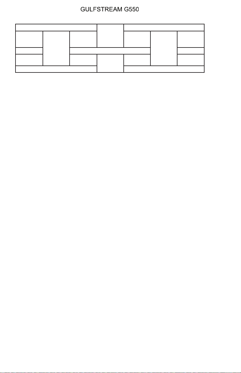
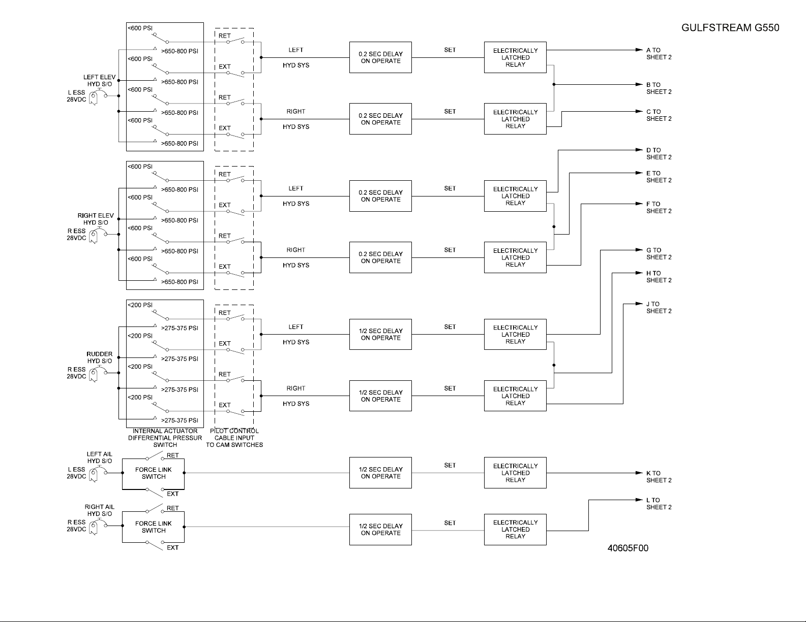
limited by a Hard Over Prevention System (HOPS), illustrated in Figure 3.
The system incorporates eight switches for each elevator to monitor
mechanical and hydraulic elevator operation. Four external mechanical
switches are integrated into the elevator control linkage to provide a
comparison reference for four switches mounted internally within the
hydraulic actuator. Of the four external switches, two are for left hydraulic
system reference and two are for right hydraulic system reference. Of the
two switches for each hydraulic system, one provides a up elevator
command reference and the other provides a down elevator command
reference. The switches are plunger-type contact switches, and are
installed on each side of a bracket attached to the command input side of
the elevator actuator. On one side of the bracket are the up elevator
command input switches for the left and right hydraulic systems. On the
other side of the bracket are the down elevator command input switches for
the left and right hydraulic systems. Inserted between the switches in the
bracket is a cam-type arm mated to the elevator hydraulic actuator output
linkage. The cam arm is positioned with a defined amount of clearance
between the plunger-type switches. Under normal conditions, the bracket
holding the switches moves with elevator command input and the cam arm
moves with the elevator hydraulic actuator output, so the clearance
between the switches and the arm is maintained.
If a malfunction occurs and the elevator moves opposite to or further from
the commanded direction, the cam arm that is attached to the output
linkage of the elevator actuator will move to close the clearance gap
between the cam arm and the plunger-type switches, making contact with
the switches on the side of the bracket. When the plungers of the switches
are depressed, a relay closes and an electrical signal is sent to a
corresponding set of switches mounted internally within the hydraulic
actuator.
Four pressure switches monitor left and right hydraulic system pressures
within the pistons of the elevator actuator. In normal conditions, all four
switches sense stabilized pressures since hydraulic outputs positioning the
elevator are balanced by air load pressures on the elevator surface acting
against actuator pressures. When a malfunction occurs and the elevator
moves contrary to the commanded direction, the hydraulic actuator shaft
moves in the contrary direction, causing an increase in hydraulic pressure
on the opposite sides of the pistons within the actuator. The left and right
system opposite side pressure switches close, completing the circuit
initiated by closure of the bracket plunger switches, and an electrical signal
is sent to a timing relay. If the contrary elevator movement persists for
longer than one tenth (1/10) of a second, hydraulic pressure from both left
an right systems is shut off to the elevator actuator.
PRODUCTION AIRCRAFT SYSTEMS 2A-27-00
Page 9
August 14/03
Page 10
OPERATING MANUAL
Title Page
Prev Page
Next Page
TOC
Left Hydraulic System Right Hydraulic System
Up
Elevator
←
Down
Elevator
→
Up
Elevator
←
Hydraulic Actuator Shaft
Pressure
Switch
Pressure
Switch
Pressure
Switch
In a similar manner, if a hydraulic malfunction causes the shaft of the
actuator to move in a direction opposite the commanded elevator direction,
the increased pressures in the wrong direction sides of the pistons would
close the monitoring switches, and movement of the actuator shaft would
cause the cam arm to contact the plunger switches on the external bracket,
and hydraulic pressure would be shut off to the elevator actuator after a
one tenth (1/10) of a second delay.
If a hydraulic malfunction in a single system (left or right) side of the
actuator moves the actuator shaft in a wrong direction, only the hydraulic
pressure of the malfunctioning system is shut off. For instance in a
stabilized condition, if the left hydraulic system piston attempts to move the
actuator shaft in the up direction, the increased pressure in the down
elevator side of the left piston will close the monitor switch and actuator
shaft displacement will close both the left and right hydraulic system up
elevator bracket plunger switches, completing the shut off circuit for the left
hydraulic system after a one tenth (1/10) second delay. (In this case
hydraulic pressure in the up elevator side of the right hydraulic system
piston will decrease due to the increase in area caused by actuator shaft
movement.) The elevator hydraulic actuator will continue to function using
the remaining hydraulic system.
The operation of the hydraulic shut off valves by the HOPS is signaled to
the MAUs (left elevator to MAU #1, right elevator to MAU #2) over ARINC429 connections. The shut off condition is monitored by the MWS, and a
CAS message corresponding to the condition is displayed on the CAS
window. If either or both hydraulic systems are shut off, an amber caution
message of “L (or) R Elevator Hydraulics Off” is displayed. If only a single
hydraulic system has been shut off, the remaining hydraulic system will
provide full elevator operation. If both hydraulic systems have been shut
off, manual elevator control may remain possible, depending upon the
cause of the hardover condition. If the cause of the condition is thought to
be momentary, and the use of the elevator is deemed necessary for
continued safe flight and landing, the hydraulic shut off valve(s) may be
reset by cycling the RIGHT ELEV HYD S/O and/or LEFT ELEV HYD S/O
circuit breaker. If the cause has not been rectified, the shut off valve(s) will
close and hydraulic boost for the elevator will be unavailable if both
hydraulic systems have been shut off. (HOPS is powered by the left
essential DC bus for the left elevator and the right essential DC bus for the
right elevator.)
To prevent the HOPS from shutting off hydraulic system pressure to the
elevator during normal flight maneuvers that may involve rapid changes in
elevator direction, HOPS activation is buffered by three elements:
• The clearance between bracket plunger switches and the actuator
Down
Elevator
→
Pressure
Switch
Page 10
August 14/03
PRODUCTION AIRCRAFT SYSTEMS2A-27-00
Page 11

OPERATING MANUAL
Title Page
Prev Page
Next Page
TOC
cam arm
• Inertia in the build up of hydraulic pressures in the elevator actuator
• The one tenth (1/10) second delay in electrically latching the shut off
of hydraulic pressure
B. Elevator Disconnect Handle:
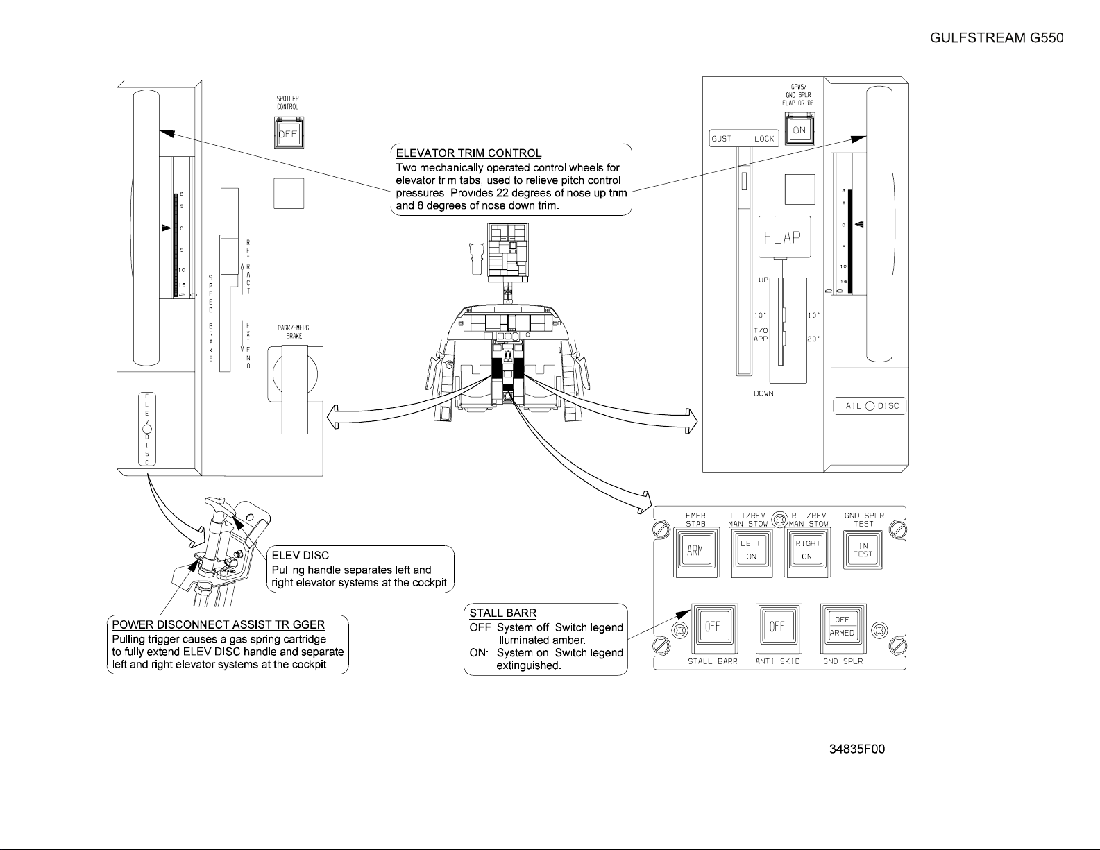
(See Figure 4.)
The mechanical torque tube beneath the cockpit connecting the pilot and
copilot yokes may be disconnected if a malfunction in one of the cable
connections, hydraulic actuators or elevators renders the respective
elevator inoperative. Disconnecting the torque tube prevents both elevators
from being disabled by a malfunction in one elevator linkage.
An elevator disconnect handle is located on the pilot side of the center
pedestal beneath a protective cover. The handle is connected by a cable to
a pin securing the two halves of torque tube together. Pulling out on the
disconnect handle removes the pin and allows each yoke to move
independently. If the elevator linkage malfunction has resulted in opposite
movement between the two yokes, making retraction of the mating pin
difficult, a power assist gas-spring cartridge may be activated to provide
additional force to remove the pin. The power assisted disconnect is
activated by pulling a trigger beneath the disconnect handle, and provides
an upward lifting moment of thirty-three feet per second (33 ft./sec).
After the yokes have been separated, the malfunctioning elevator is
isolated and the operable elevator may be used to control the aircraft. with
manual or autopilot inputs. If it is discovered that separating the yokes
freed the previously malfunctioning elevator linkage, the yokes may be
reconnected by pushing in on the disconnect handle when the yokes are
aligned, provided that the power assist disconnect was not used.Areset of
the yoke torque tube coupling is not possible without special maintenance
tools after activation of the power assist disconnect.
C. Pitch Trim System:
(See Figure 4 through Figure 6.)
Each elevator has a trim tab installed on the trailing edge. The trim tabs are
manufactured from the same graphite-epoxy material as the elevators, but
incorporate a ceramic heating element that is continuously electrically
powered to maintain a temperature of one hundred seventy-five degrees
Fahrenheit, plus or minus twenty degrees (175°F±20) around the tab
actuator linkage. Elevator trim heat is powered by 115V AC from the right
main bus. The trim tabs have a range of movement of twenty-two degrees
(22°) trailing edge down (aircraft nose up) to eight degrees (8°) trailing
edge up (aircraft nose down). Limit switches are installed at the travel limits
that will prompt the display of Crew Alerting System (CAS) messages
notifying the crew that the elevator trim tabs are at maximum displacement.
If a trim limit message is displayed while the autopilot is engaged, extreme
care should be taken prior to disengaging the autopilot. An abrupt attitude
change will occur if trim displacement is not moderated prior to
disengaging the autopilot.
Operation of the trim tabs employs aerodynamic force to maintain the
elevator in the desired position. As the trim tab is moved from the neutral
position (faired with the elevator) into the airstream, the air impinging on
PRODUCTION AIRCRAFT SYSTEMS 2A-27-00
Page 11
August 14/03
Page 12

OPERATING MANUAL
Title Page
Prev Page
Next Page
TOC
the tab forces the hinged elevator into the opposite direction. As the
elevator is moved from the neutral position (faired with the horizontal
stabilizer), it also encounters pressure forces from the airstream, thus the
amount of elevator movement from neutral is determined by a balance of
airstream forces acting on both the trim tab and the elevator. Since the
surface area of the trim tab exposed to the airstream is less than the
surface area of the elevator, the elevator is deflected in much smaller
increments than trim tab displacement (excluding other factors, trim tab
effectiveness is a ratio of tab surface area to elevator surface area).
The flight crew manually controls the amount of trim tab deflection by
moving control wheels on either side of the center console. The wheels are
hubs connected to a common axial shaft, so that moving one wheel moves
the other. The shaft is connected to a continuous loop of wire cables that
connect through a series of pulleys and bellcranks to the elevator trim tabs.
Rotating a trim wheel forward positions the trim tab up forcing the elevator
down resulting in an aircraft nose down moment. Trim wheel rotation aft
results in an aircraft nose up moment.
The flight crew has the option of electrically moving the elevator trim tabs.
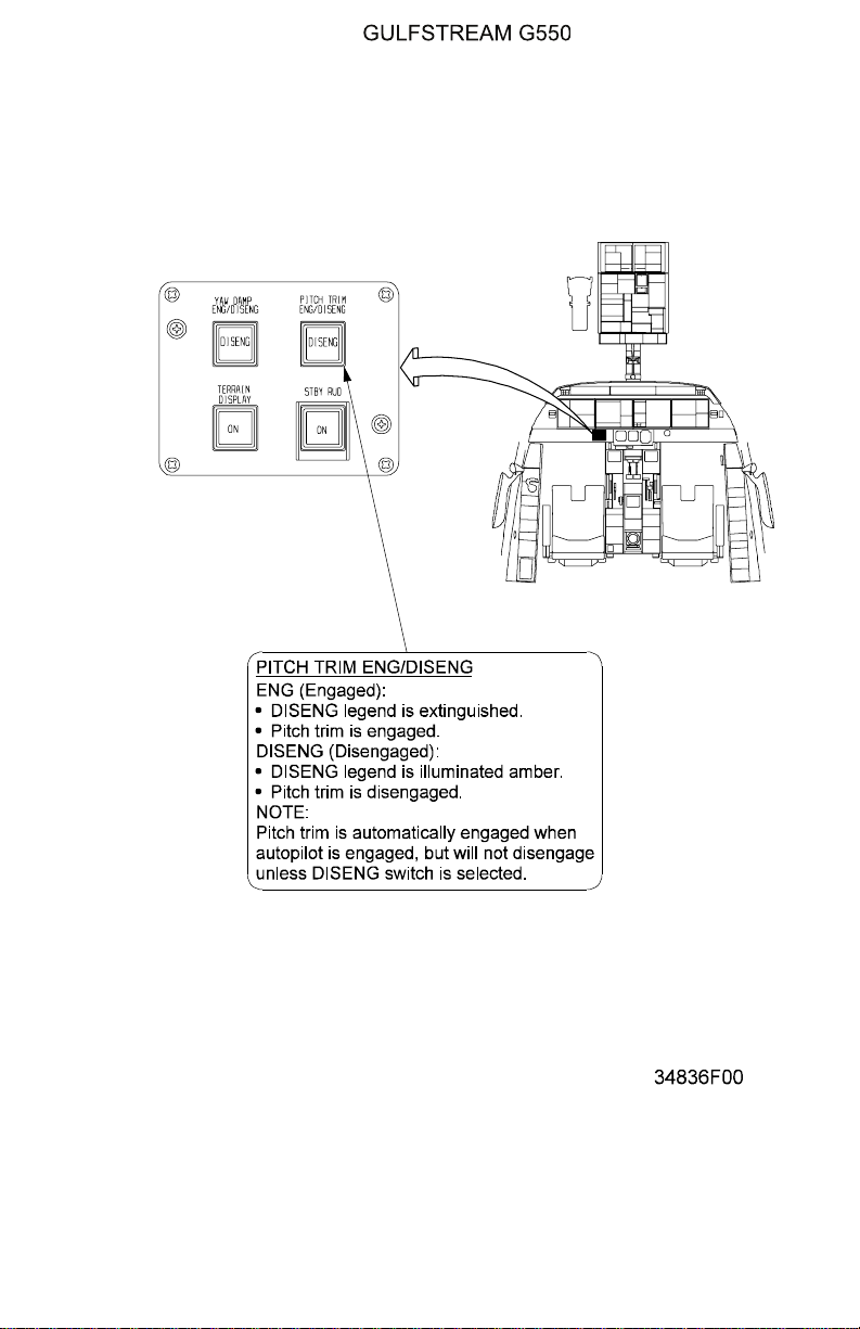
A pushbutton, labelled PITCH TRIM ENG / DISENG, located to the left of
the standby flight instruments on the lower instrument panel enables
electrical operation of trim switches mounted on the outboard side of the
control yokes. Electric pitch trim is normally engaged. The amber DISENG
legend in the pushbutton will illuminate if the button is not pushed in to
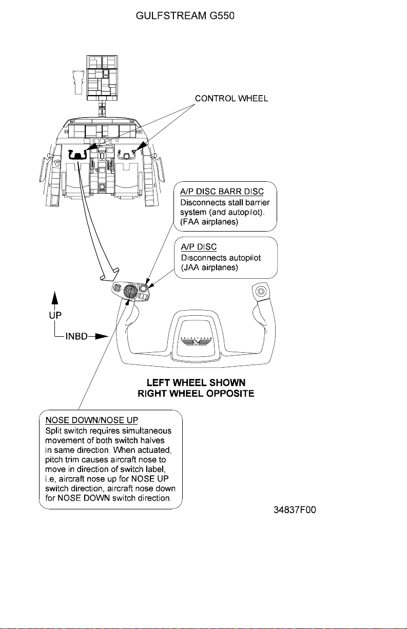
engage electric trim. The yoke trim switches are composed of split halves.
Both halves must be moved in the same direction to move the elevator
trim. The split switch design helps to prevent accidental trim input. The
switches are wired to an electric servomotor that is located in the tail of the
aircraft and incorporated into the cable linkage to the trim tabs. An electric
signal from a cockpit trim switch results in the servomotor rotating an
attached pulley, moving the elevator trim cable loop in the desired
direction. The manual trim wheels on the pedestal will rotate with electric
trim inputs, since the control cabling is a continuous loop.
When the autopilot is engaged, autopilot servomotors move the elevators
and also control elevator trim with the same servomotor employed by the
yoke electric trim switches. The PITCH TRIM ENG / DISENG switch is
automatically engaged whenever the autopilot is engaged (to enable
autopilot trim). However the reverse is not true - electric pitch trim will not
disengage when the autopilot is disengaged, but must be selected off with
the switch.
Elevator trim must be within a defined range for takeoff, with the specific
setting within the range determined by aircraft Center of Gravity (COG) and
takeoff gross weight. The limits of the acceptable pitch trim range are eight
degrees nose up to nineteen degrees nose up (8° - 19° up). The takeoff
elevator trim range is marked in green on the trim setting indices of the
manual trim wheels at each side of the center pedestal. The same limits
are shown in a green band on the trim scale of the Flight Controls 2/3
synoptic page. Failure to set pitch trim within the defined range will result in
a warning annunciation and CAS message as the power levers are
advanced for takeoff.
Page 12
August 14/03
PRODUCTION AIRCRAFT SYSTEMS2A-27-00
Page 13
OPERATING MANUAL
Title Page
Prev Page
Next Page
TOC
D. Mach Trim:
The autopilot employs elevator control to provide the aircraft with Mach
trim. Mach trim is necessary because at high speed flight the center of lift
on the wing transits aft with increases in speed, producing a nose down
pitch moment termed Mach tuck. The autopilot electrically repositions the
elevator trim to neutralize the nose down force. Mach trim is an automatic
function of the Flight Guidance Computers.
NOTE:
The autopilot does not have to be engaged to provide
Mach trim. Automatic Mach trim is available whenever
the PITCH TRIM ENG/DISENG switch is engaged.
3. Controls and Indications:
(See Figure 4 through Figure 6.)
NOTE:
A full description of the Flight Controls 2/3 synoptic
page appears in section 2B-07-00.
A. Circuit Breakers (CBs):
The following CBs protect elevator pitch control:
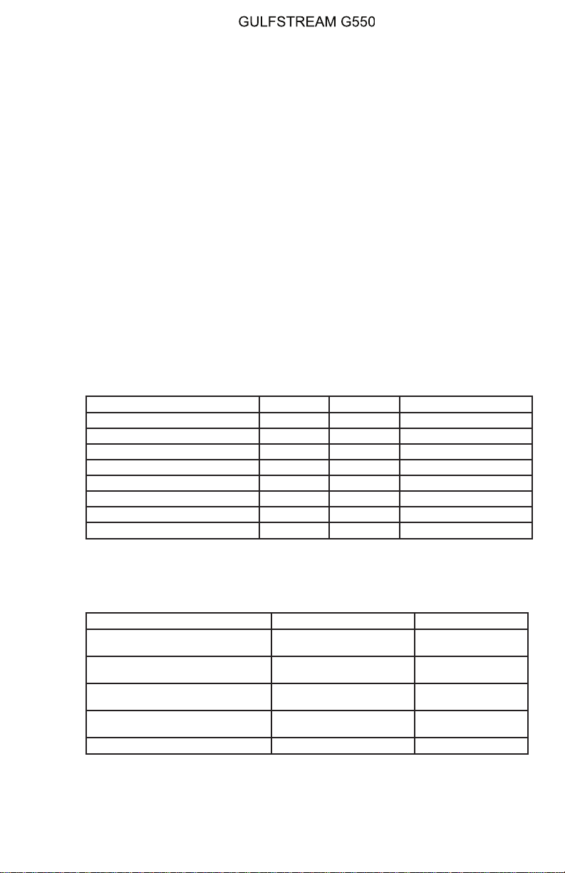
Circuit Breaker Name: CB Panel: Location: Power Source:
ELEV SERVO #1 POP D-4 L ESS DC Bus
ELEV SERVO #2 CPOP D-4 R ESS DC Bus
PITCH TRIM SERVO #1 POP E-2 L ESS DC Bus
PITCH TRIM SERVO #2 CPOP E-1 R ESS DC Bus
L ELEV TRIM HEAT REER E-16 R MAIN AC Bus
R ELEV TRIM HEAT REER F-16 R MAIN AC Bus
LEFT ELEV HYD S/O POP C-5 L ESS DC Bus
RIGHT ELEV HYD S/O CPOP C-5 R ESS DC Bus
B. Crew Alerting System (CAS) Messages:
The following CAS messages are associated with the elevator pitch
controls:
Area Monitored: CAS Message: Message Color:
Elevator Trim Tab RVDTs vrs
takeoff range
Elevator and Trim Tab RVDTs and
MAUs
Elevator and Trim Tab RVDTs and
MAUs
L/R Elevator HOPS and MAUs L/R Elevator Hydraulics
Aircraft Configuration Red
Elevator Mistrim Nose
Down
Amber
Elevator Mistrim Nose Up Amber
Off
Amber
Electric Pitch Trim Servos Elevator Trim 1-2 Fail Amber
PRODUCTION AIRCRAFT SYSTEMS 2A-27-00
Page 13
August 14/03
Page 14
OPERATING MANUAL
Title Page
Prev Page
Next Page
TOC
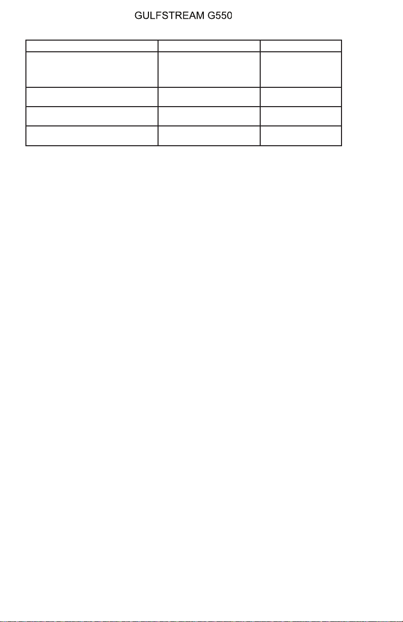
Area Monitored: CAS Message: Message Color:
Electric Pitch Trim Servos / Trim
ENG/DISENG Switch
Electric Pitch Trim Servos and
MAUs
Electric Pitch Trim Servos and
MAUs
Electric Pitch Trim Servos and
MAUs
Mach Trim Off
(inhibited below 0.82
Mach)
NOTE
Amber
Pitch Trim 1-2 Power Fail Blue
Elevator Trim Down Limit Blue
Elevator Trim Up Limit Blue
4. Limitations:
A. Mach Trim / Electric Elevator Trim Functions:
(1) Use of Mach Trim / Electric Elevator Trim Functions:
Mach trim / electric elevator trim must be ON during all flight
operations except as provided for in Section 05-02-40: Mach Trim
Failure.
(2) With both Mach Trim / Electric Elevator Trim Inoperative:
M
is reduced to 0.80MT.
mo
Page 14
August 14/03
PRODUCTION AIRCRAFT SYSTEMS2A-27-00
Page 15
OPERATING MANUAL
Title Page
Prev Page
Next Page
TOC
Hard Over Prevention
System (HOPS)
Figure 3 (Sheet 1 of 2)
2A-27-00
Page 15 / 16
August 14/03
Page 16

Title Page
Prev Page
Next Page
TOC
Page 17

OPERATING MANUAL
Title Page
Prev Page
Next Page
TOC
Hard Over Prevention
System (HOPS)
Figure 3 (Sheet 2 of 2)
2A-27-00
Page 17 / 18
August 14/03
Page 18

Title Page
Prev Page
Next Page
TOC
Page 19
OPERATING MANUAL
Title Page
Prev Page
Next Page
TOC
Pitch Flight Controls
System Controls and
Indications (Cockpit
Center Pedestal)
Figure 4
2A-27-00
Page 19 / 20
August 14/03
Page 20

Title Page
Prev Page
Next Page
TOC
Page 21
OPERATING MANUAL
Title Page
Prev Page
Next Page
TOC
Electric Pitch Trim Engage / Disengage Switch Controls and Indications
Figure 5
PRODUCTION AIRCRAFT SYSTEMS 2A-27-00
Page 21
August 14/03
Page 22
OPERATING MANUAL
Title Page
Prev Page
Next Page
TOC
Page 22
August 14/03
Electric Pitch Trim / Stall Barrier System Controls and Indications
Figure 6
PRODUCTION AIRCRAFT SYSTEMS2A-27-00
Page 23

OPERATING MANUAL
Title Page
Prev Page
Next Page
TOC
2A-27-30: Rudder Yaw Control
1. General Description:
The flight crew controls the direction of the aircraft around the vertical axis by
movement of the rudder. The rudder panel is composed of graphite-epoxy fabric
baked at high temperatures to form a strong but light weight structure. The rudder
is positioned by inputs from the pilot or copilot rudder pedals, or by autopilot
electro-servos. The pilot and copilot rudder pedals are connected by a common
torque tube so that either may control rudder movement. (The individual pedal
pairs are adjustable to accommodate differences in pilot leg length.) The common
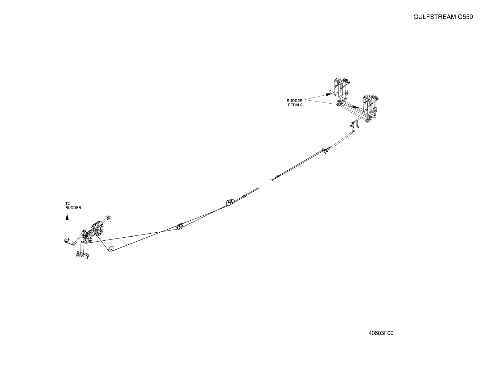
torque tube is connected by a bellcrank to a single stranded wire cable loop
located on the right side of the aircraft beneath the cockpit and cabin floor.(Since
there is only one rudder flight control surface, there is no need for dual cable
linkages from both yokes to the rudder, nor is there a need for a system to
separate pilot and copilot rudder pedal inputs to the rudder.) The cable loop
incorporates pulleys and bellcranks to route the cable around other installations
beneath the aircraft floor. At the end of the loop is a bellcrank connected to a dual
piston hydraulic actuator. The bellcrank translates movement of the control cable
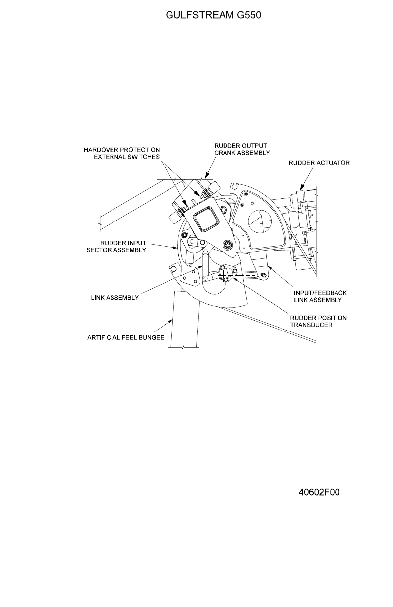
into lateral displacement inputs to the actuator. The rudder control cable linkage is
illustrated in Figure 7 and the termination of the cable linkage at the rudder
actuator is shown in Figure 8. The actuator has a single shaft with a piston
chamber for each (left and right) hydraulic system. Both hydraulic systems
provide up to three thousand (3,000) psi pressure to assist in moving the rudder
surface. Internal regulator valves limit the pressure output of the two pistons within
the hydraulic actuator to a maximum of fifteen hundred (1,500) psi each to prevent
structural damage to the rudder and vertical stabilizer. The output end of the
hydraulic actuator shaft is connected to linkages that move the rudder around the
pivot point connections on the vertical stabilizer. If one hydraulic system fails, the
regulator valve of the remaining system shifts to provide up to three thousand
(3,000) psi to move the rudder. Additionally, in the event of dual hydraulic system
failures, the auxiliary (AUX) hydraulic pump will power the rudder using the left
system piston in the actuator provided sufficient fluid remains in the auxiliary
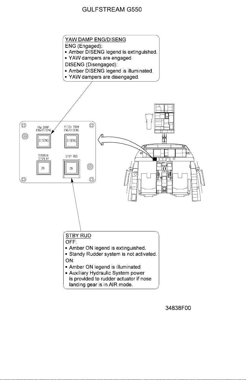
reservoir of the left hydraulic system. AUX hydraulic system power for the rudder
is activated by the selection of the STBY RUD (Standby Rudder) switch on the
lower portion of the pilot instrument panel to the left of the standby flight
instruments.
Mechanical stops are incorporated into the rudder mounting structure to physically
limit rudder displacement to a maximum of twenty-two degrees (22°) either side of
neutral, although full displacement is available only at low airspeeds. As airspeed
increases, the airload on the rudder surface increases proportionally. When the
airload on the rudder surface equals the available hydraulic pressure output of the
rudder actuator, no further rudder displacement is possible. The Monitor and
Warning System (MWS) software monitors aircraft speed, angle of attack and
rudder displacement to formulate an advisory message informing the flight crew
when maximum rudder displacement has been reached.
2. Description of Subsystems, Units and Components:
A. Yaw Damper and Autopilot Rudder Operation:
Automatic rudder compensation for aircraft yaw produced by dutch roll
inherent to swept-wing aircraft is provided by the yaw damper function of
the autopilot. The yaw damper function is engaged with the YAW DAMP
ENG / DISENG switch located on the lower pilot side instrument panel
PRODUCTION AIRCRAFT SYSTEMS 2A-27-00
Page 23
August 14/03
Page 24

OPERATING MANUAL
Title Page
Prev Page
Next Page
TOC
adjacent to the STBY RUD switch, shown in Figure 9. The yaw damper is
normally engaged even if the autopilot is not operating. (The DISENG
legend in the switch will be illuminated amber if the yaw damper is not
engaged.) If the autopilot is engaged, the yaw damper must be engaged,
since autopilot rudder commands use the yaw damper circuits to displace
the rudder.
The yaw damper function is a redundant dual-channel installation. Yaw
damper channel #1 is controlled by the autopilot function hosted in
processor modules in Modular Avionics Unit (MAU) #1, channel #2 by MAU
#2. Each channel has a dedicated Electro-Hydraulic Servo Valve (EHSV)
internal to the rudder actuator. The autopilot processor detects an
uncommanded yaw displacement by monitoring data from the Inertial
Reference Units (IRUs). The autopilot processor signals a rudder
displacement to counter the aircraft yaw through an Actuator Input/Output
Processor (AIOP) module via ARINC-429 bus connection to the EHSV on
the rudder actuator. The amount of rudder displacement necessary is a
function of airspeed / Mach number, and the AIOP uses information from
the Air Data Application (ADA) in the MAU to determine the amount of
rudder to apply. A feedback loop from a Rotary Variable Displacement
Transducer to the AIOP confirms the rudder position. The maximum
amount of rudder displacement available to the yaw damper is five degrees
(5°).
Since only one yaw damper channel is necessary for rudder control, the
active channel alternates on each flight segment (a function of weight-onwheels) to prolong system life. If the active channel fails, the standby
channel will automatically assume yaw damper control.
The yaw damper function also provides a rudder input for aircraft turn
coordination provided the flaps are not set to thirty degrees (30°) or more.
The yaw damper will add up to five degrees (5°) of rudder in the direction
of turn without pilot rudder input.
Autopilot control of the rudder is the same functional process as the yaw
damper, but the amount of rudder displacement available to the autopilot is
greater (up to the 22° limit). Larger rudder inputs are necessary for the
lower airspeeds associated with coupled approaches or during single
engine operations.
B. Rudder Trim:
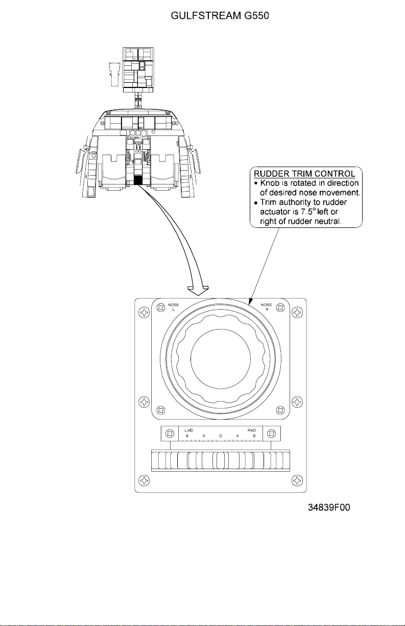
The rudder is trimmed by manual inputs from the trim wheel mounted on
the cockpit aft center pedestal (see Figure 10). There is no trim tab on the
rudder, rather the whole rudder panel moves in response to trim input. The
rudder may be displaced up seven and a half degrees (7½°) left or right
with trim commands. Rotation of the trim wheel moves a cable linkage to a
drum mounted adjacent to the rudder hydraulic actuator. Movement of the
trim wheel rotates the drum and a linkage attached to the drum moves the
shaft of the rudder actuator. The rudder actuator hydraulically positions the
rudder by the commanded amount of deflection, and the linkage from the
drum establishes the trimmed rudder position as a new neutral setting for
the actuator. Manual or yaw damper / autopilot rudder deflections are then
summed to the existing trimmed rudder displacement. (The autopilot does
not have a separate trim input to the rudder.)
Page 24
August 14/03
PRODUCTION AIRCRAFT SYSTEMS2A-27-00
Page 25

OPERATING MANUAL
Title Page
Prev Page
Next Page
TOC
C. Rudder Limiting:
The G550 does not have a separate load limiter unit, but relies instead
upon MWS software to compute maximum rudder deflection for a given
airspeed, matching airloads on the rudder surface with the hydraulic
function of the rudder actuator.Although at low airspeeds full rudder travel
of twenty-two degrees (22°) is available, at higher airspeeds less rudder
travel is necessary to achieve the desired amount of aircraft heading
control. To avoid excessive loads, the rudder hydraulic actuator uses
internal pressure switches to signal the MWS when full hydraulic pressure
output of the actuator has been reached. The MWS formulates a CAS blue
advisory message text of “Rudder Limit” for display on the CAS window
indicating the maximum rudder hydraulic power assist condition.
The amount of rudder deflection at which maximum rudder hydraulic assist
occurs is dependent upon airspeed. As speed increases, air loads increase
as the rudder is displaced. Since the rudder surface is linked mechanically
to the rudder hydraulic actuator shaft, the force of the rudder airload
opposes the force of the hydraulic system(s) moving the actuator.
Whenever the airload force equals hydraulic system force (1,500 psi with
both left and right systems operating or 3,000 psi with a single hydraulic
system) no further rudder displacement is possible, and the “Rudder Limit”
advisory message is displayed on the CAS window.
D. Rudder Hard Over Prevention System (HOPS):
Movements of the rudder contrary to the commanded position are limited
by a Hard Over Prevention System (HOPS) that incorporates eight
switches to monitor mechanical and hydraulic rudder operation (see Figure
3. Four external mechanical switches are integrated into the rudder control
linkage to provide a comparison reference for four switches mounted
internally within the hydraulic actuator. The external HOPS switches are
noted on Figure 8. Of the four external switches, two are for left hydraulic
system reference and two are for right hydraulic system reference. Of the
two switches for each hydraulic system, one provides a left rudder
command reference and the other provides a right rudder command
reference. The switches are plunger-type contact switches, and are
installed on each side of a bracket attached to the command input side of
the rudder actuator. On one side of the bracket are the left rudder
command input switches for the left and right hydraulic systems. On the
other side of the bracket are the right rudder command input switches for
the left and right rudder systems. Inserted between the switches in the
bracket is a cam-type arm mated to the rudder hydraulic actuator output
linkage. The cam arm is positioned with a defined amount of clearance
between the plunger-type switches. Under normal conditions, the bracket
holding the switches moves with rudder command input and the cam arm
moves with the rudder hydraulic actuator output, so the clearance between
the switches and the arm is maintained.
If a malfunction occurs and the rudder moves opposite to or further from
the commanded direction, the cam arm that is attached to the output
linkage of the rudder actuator will move to close the clearance gap
between the cam arm and the plunger-type switches, making contact with
the switches on the side of the bracket. When the plungers of the switches
are depressed, a relay closes and an electrical signal is sent to a
corresponding set of switches mounted internally within the hydraulic
PRODUCTION AIRCRAFT SYSTEMS 2A-27-00
Page 25
August 14/03
Page 26
OPERATING MANUAL
Title Page
Prev Page
Next Page
TOC
actuator.
Four pressure switches monitor left and right hydraulic system pressures
within the pistons of the rudder actuator. In normal conditions, all four
switches sense stabilized pressures since hydraulic outputs positioning the
rudder are balanced by air load pressures on the rudder surface acting
against actuator pressures. When a malfunction occurs and the rudder
moves contrary to the commanded direction, the hydraulic actuator shaft
moves in the contrary direction, causing an increase in hydraulic pressure
on the opposite sides of the pistons within the actuator. The left and right
system opposite side pressure switches close, completing the circuit
initiated by closure of the bracket plunger switches, and an electrical signal
is sent to a timing relay. If the contrary rudder movement persists for longer
than one half (½) second, hydraulic pressure from both left an right
systems is shut off from the rudder actuator.
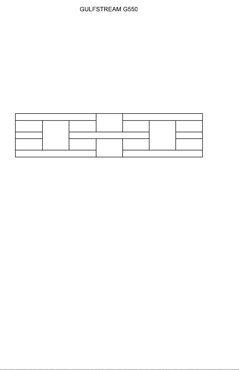
Left Hydraulic System Right Hydraulic System
Left
Rudder ←
Right
Rudder →
Left
Rudder ←
Hydraulic Actuator Shaft
Pressure
Switch
Pressure
Switch
Pressure
Switch
In a similar manner, if a hydraulic malfunction causes the shaft of the
actuator to move in a direction opposite the pilot or yaw damper / autopilot
commanded direction, the increased pressures in the wrong direction sides
of the pistons would close the monitoring switches, and movement of the
actuator shaft would cause the cam arm to contact the plunger switches on
the external bracket, and hydraulic pressure would be shut off to the rudder
actuator after a one half (½) second delay.
If a hydraulic malfunction in a single system (left or right) side of the
actuator moves the actuator shaft in a wrong direction, only the hydraulic
pressure of the malfunctioning system is shut off. For instance in a
stabilized rudder condition, if the left hydraulic system piston attempts to
move the actuator shaft to the right, the increased pressure in the right side
of the left piston will close the monitor switch and actuator shaft
displacement will close both the left and right hydraulic system bracket
plunger switches, completing the shut off circuit for the left hydraulic
system after a one half (½) second delay. (In this case hydraulic pressure
in the right rudder side of the right hydraulic system piston will decrease
due to the increase in area caused by actuator shaft movement.) The
rudder hydraulic actuator will continue to function using the remaining
hydraulic system. During single hydraulic system operation the pressure
regulator valve will open, allowing the remaining hydraulic system pressure
output to increase up to three thousand (3,000) psi for rudder actuation.
The operation of the hydraulic shut off valves by the HOPS is signaled to
MAU #2 over an ARINC-429 connection. The shut off condition is
monitored by the MWS, and a CAS message corresponding to the
condition is displayed on the CAS window. If both hydraulic systems are
shut off, an amber caution message of “Rudder Hydraulics Off” is
displayed. Manual rudder control may remain possible, depending upon
Right
Rudder →
Pressure
Switch
Page 26
August 14/03
PRODUCTION AIRCRAFT SYSTEMS2A-27-00
Page 27

OPERATING MANUAL
Title Page
Prev Page
Next Page
TOC
the cause of the hardover condition. If the cause of the condition is thought
to be momentary, and the use of the rudder is deemed necessary for
continued safe flight and landing, the hydraulic shut off valves may be reset
by cycling the RUDDER HYD S/O circuit breaker. If the cause has not been
rectified, the shut off valves will close and hydraulic boost for the rudder will
be unavailable. Loss of rudder hydraulic pressure will also prevent yaw
damper (and autopilot rudder) operation.
If only one hydraulic system is shut off to the rudder, the remaining system
will provide full boost to the rudder and yaw damper / autopilot rudder
operation. The amber caution CAS message of ”Rudder Hydraulics Off will
be accompanied by a blue advisory “Single Rudder” message.
To prevent the HOPS from shutting off hydraulic system pressure to the
rudder during normal flight maneuvers that may involve rapid changes in
rudder direction, HOPS activation is buffered by three elements:
• The clearance between bracket plunger switches and the actuator
cam arm
• Inertia in the build up of hydraulic pressures in the rudder actuator
• The one half (½) second delay in electrically latching the shut off of
hydraulic pressure
E. Standby Rudder System:
In the event that both hydraulic systems fail during flight, the Auxiliary
(AUX) hydraulic pump can be used to pressurize the left hydraulic system
to actuate the rudder and yaw damper provided that fluid remains in the left
system reservoir and there is no leak in the left hydraulic system lines
connecting to the rudder actuator. The AUX hydraulic pump, located in the
right main landing gear wheel well, is powered by left essential DC bus and
can provide three thousand (3,000) psi at a flow rate of two (2) gallons per
minute. Normally the AUX is used to actuate the flaps, ground spoiler
servos, brakes and nose wheel steering in the event of a dual hydraulic
system failure. However a valve in the left hydraulic system plumbing,
controlled by the STBY RUD switch on the lower portion of the pilot
instrument panel, can be used to divert the total output of the AUX
hydraulic pump to the left hydraulic system piston of the rudder actuator.
Powering the rudder and yaw damper, especially at higher altitudes,
provides dutch roll compensation and avoids the airspeed restrictions
necessary without an operating yaw damper. As the aircraft descends to
lower altitudes and airspeeds during the approach phase, airloads on the
rudder are reduced and manual rudder control is adequate for steering
commands. The STBY RUD switch can then be selected off to enable the
AUX hydraulic pump to provide the pressure for flap extension, pressurize
ground spoiler servos, wheel brakes and nose wheel steering during
landing. If the STBY RUD switch is not selected off prior to landing, the
standby rudder valve will automatically close when the nose gear weighton-wheels (WOW) switch is compressed on landing, enabling AUX pump
power for stopping and steering the aircraft.
PRODUCTION AIRCRAFT SYSTEMS 2A-27-00
Page 27
August 14/03
Page 28
OPERATING MANUAL
Title Page
Prev Page
Next Page
TOC
3. Controls and Indications:
(See Figure 9 and Figure 10.)
NOTE:
A full description of the Flight Controls 2/3 and
Hydraulics 2/3 synoptic pages appears in section
2B-07-00.
A. Circuit Breakers (CBs):
The following CBs protect the rudder flight controls:
Circuit Breaker Name: CB Panel: Location: Power Source:
RUDDER HYD S/O CPOP C-3 R ESS DC Bus
YAW DAMP SERVO #1 POP D-6 L ESS DC Bus
YAW DAMP SERVO #2 CPOP D-6 R ESS DC Bus
AUX HYD PUMP LEER C-16 L ESS DC Bus
B. Crew Alerting System (CAS) Messages:
The following CAS messages are associated with the yaw flight controls
system:
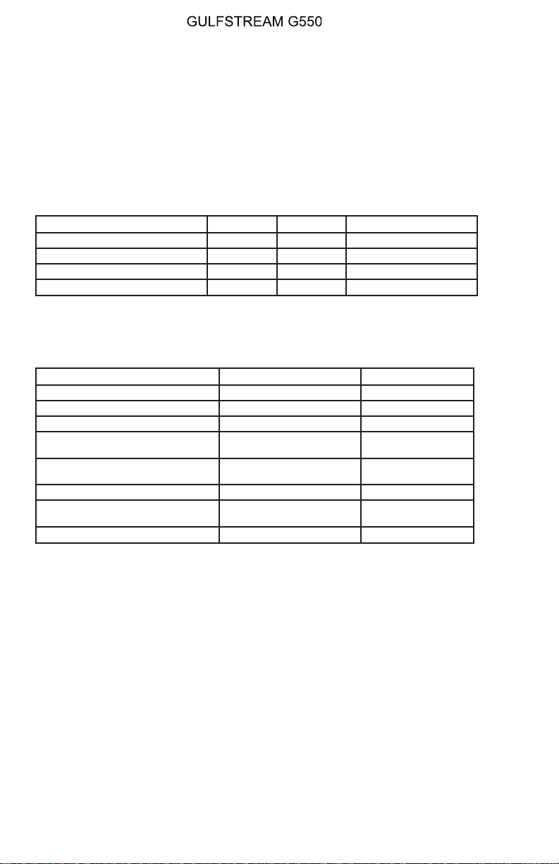
Area Monitored: CAS Message: Message Color:
Rudder Hydraulic Shutoff Valves Rudder Hydraulics Off Amber
Yaw Damper Servo Valves Yaw Damper 1-2 Fail Amber
YAW DAMP ENG/DISENG Switch Yaw Damper Off Amber
Autopilot, YAW DAMP ENG/
DISENG Switch
MWS Software, Aircraft Speed,
Rudder Position (RVDT)
No YD Turn Coordination Blue
Rudder Limit Blue
Rudder Hydraulic Shutoff Valves Single Rudder Blue
Standby Rudder Switch / AUX
Pump
Standby Rudder Hyd On Blue
Yaw Damper Servo Valves YD 1-2 Power Fail Blue
4. Limitations:
Page 28
August 14/03
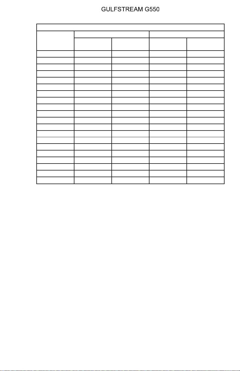
A. Yaw Damper Inoperative Speeds:
Maximum Speeds:
• Above 10,000 Feet: 260 KTS / 0.80 MT
• Below 10,000 Feet: 250 KCAS
Minimum Speeds:
• Above 20,000 Feet: 210 KTS
• Below 20,000 Feet:
The minimum speed is in accordance with the following schedule
until ready to configure for approach and landing. V
the airspeed tape of the PFD, is the approach speed for landing for
the current flap setting.
PRODUCTION AIRCRAFT SYSTEMS2A-27-00
REF, as shown on
Page 29
Minimum Speeds: Yaw Damper Inoperative
Title Page
Prev Page
Next Page
TOC
Flaps 0, 10,
Fuel - lb
23,000 V
24,000 V
25,000 V
26,000 V
27,000 V
28,000 V
29,000 V
30,000 V
31,000 V
32,000 V
33,000 V
34,000 V
35,000 V
36,000 V
37,000 V
38,000 V
39,000 V
40,000 V
41,000 V
41,300 V
OPERATING MANUAL
Sea Level to 5000 ft 5000 to 20,000 ft
20
REF VREF VREF 135
REF VREF VREF 141
REF VREF VREF 147
REF VREF VREF 153
REF VREF VREF 159
REF VREF 147 160
REF VREF 153 160
REF VREF 158 160
REF VREF 163 160
REF VREF 168 160
REF VREF 174 160
REF VREF 179 160
REF VREF 184 160
REF VREF 189 160
REF VREF 195 160
REF VREF 200 160
REF VREF 205 160
REF VREF 211 160
REF VREF 216 160
REF VREF 217 160
Flaps 39
Flaps 0, 10,
20
Flaps 39
PRODUCTION AIRCRAFT SYSTEMS 2A-27-00
Page 29
August 14/03
Page 30

OPERATING MANUAL
Title Page
Prev Page
Next Page
TOC
THIS PAGE IS INTENTIONALLY LEFT BLANK.
Page 30
August 14/03
PRODUCTION AIRCRAFT SYSTEMS2A-27-00
Page 31
OPERATING MANUAL
Title Page
Prev Page
Next Page
TOC
Rudder Control Cable
Linkage
Figure 7
2A-27-00
Page 31 / 32
August 14/03
Page 32

Title Page
Prev Page
Next Page
TOC
Page 33
OPERATING MANUAL
Title Page
Prev Page
Next Page
TOC
Control Cable Termination at Rudder Actuator
Figure 8
PRODUCTION AIRCRAFT SYSTEMS 2A-27-00
Page 33
August 14/03
Page 34
OPERATING MANUAL
Title Page
Prev Page
Next Page
TOC
Page 34
August 14/03
Yaw Flight Controls System Controls and Indications
Figure 9
PRODUCTION AIRCRAFT SYSTEMS2A-27-00
Page 35
OPERATING MANUAL
Title Page
Prev Page
Next Page
TOC
Rudder Trim Controls
Figure 10
PRODUCTION AIRCRAFT SYSTEMS 2A-27-00
Page 35
August 14/03
Page 36

OPERATING MANUAL
Title Page
Prev Page
Next Page
TOC
2A-27-40: Aileron Roll Control
1. General Description:
The flight crew controls the motion of the aircraft around the longitudinal axis by
displacement of the ailerons. The ailerons, composed of baked epoxy graphite
fabric, are mechanically linked to the pilot and copilot control yokes by a dual
installation of multi-strand braided cables and a system of pulleys and bellcranks.
A hydraulic actuator is incorporated in the cable linkage of each aileron to provide
a powered assist in deflecting the ailerons. The hydraulic actuators provide a
boost advantage of six to one (6 : 1) to pilot manual yoke inputs. Rotation of the
control yokes left or right produce a roll in the corresponding direction. Each
control yoke is linked to one aileron: the pilot yoke is cable-linked to the left aileron
and the copilot yoke is cable-linked to the right aileron. Although the ailerons are
independently linked, the control yokes are coupled together by a mechanical arm
beneath the cockpit floor so that rotation of one yoke will rotate the other yoke,
producing motion in both ailerons. Like the elevator system previously described,
the link between the control yokes may be separated if a malfunction causes one
aileron to become inoperative. A disconnect handle on the copilot side of the
center pedestal can be pulled out to separate the link between the yokes, allowing
independent operation of the free (unjammed) aileron.
Operation of the ailerons is symmetrical but opposite. If a control yoke is rotated to
the left to command a left roll, the aileron on the trailing edge of the right wing
deflects downward, producing a small change in the chord of a section of the
wing, and creating lift. The right wing then rises due to the increased lift
component. At the same time the aileron on the left wing trailing edge deflects
upward, disrupting airflow over the wing and decreasing lift. The left wing falls due
to the decrease in lift on a portion of the wing. A roll in the opposite direction is
accomplished by reversing the direction of the aileron deflection, creating the
same circumstances on opposite wings. The maximum aileron deflection is
eleven degrees (11°) up or down.
To increase the response time for roll commands, two of the three spoiler panels
on each wing are mechanically coupled to the aileron control cable linkage. The
two outboard spoilers on the falling wing (with the aileron deflected up) deploy,
creating additional disruption of airflow over the wing to increase roll rates. The
spoiler panels on the upward moving wing (with aileron deflected downward) do
not move, remaining faired with the upper wing surface.
A single trim tab on the left aileron is manually positioned to reduce control yoke
forces in maintaining a stabilized condition around the longitudinal axis. An aileron
trim wheel on the aft section of the cockpit center pedestal is linked by a cable
directly to the trim tab. The trim wheel is rotated left and right to produce the
corresponding trim input to position the left aileron. Since the ailerons are linked
through the mechanical connection between the control yokes, moving the left
aileron will move the right aileron in the opposite direction for a equal amount of
deflection. The trim tab has a ceramic surface surrounding the hinge points that is
heated to prevent ice formation that might interfere with tab operation.
The autopilot is integrated into the cable linkage to the ailerons through electric
servos. The aileron cables are wrapped around a drum driven by the servos. The
autopilot servos rotate the drum, producing cable inputs to position the ailerons.
Page 36
August 14/03
NOTE:
The autopilot has no trim input to the ailerons
PRODUCTION AIRCRAFT SYSTEMS2A-27-00
Page 37

OPERATING MANUAL
Title Page
Prev Page
Next Page
TOC
The ailerons, like the other primary flight controls, are monitored for correct
operation by a Hard Over Prevention System (HOPS). The HOPS will shut off
hydraulic pressure to both aileron actuators if aileron movement does not
correspond to flight crew of autopilot commands.
If no hydraulic pressure is available to the aileron actuators, the hydraulic control
valves of the actuators will bypass any residual pressure and full aileron deflection
will be available using manual control inputs from the cockpit yokes. A slower
response time to aileron manual operation can be expected due to the lack of
boost authority and the absence of assist from the flight spoilers (if the spoilers
cannot be hydraulically powered).
2. Description of Subsystems, Units and Components:
A. Aileron Control Linkage:
Rotation of each control yoke produces a parallel rotation of the other yoke
through the mechanical arm beneath the cockpit floor. As both yokes rotate
bellcranks translate rotational movement into linear displacement of the
control cables leading to the hydraulic actuators that move the ailerons.
Integrated into the cable linkage are the autopilot electric servos and a
series of bellcranks and linkages to route the cables around existing
equipment beneath the cabin floor. The aileron cable links transit aft along
the fuselage until reaching the aft bulkheads of the main landing gear
wheel wells. At this point the cables pass though pulleys that translate the
forward and aft motion of the cables ninety degrees (90°) and out the aft
face of each main wing beam. The cable linkages connect to the flight
spoiler mixing and summing links and continue out to the aileron hydraulic
actuators. The hydraulic actuators are located on the aft wing beam
between the flaps and the ailerons. The actuators boost manual or
autopilot control inputs and position the ailerons in the commanded
direction.
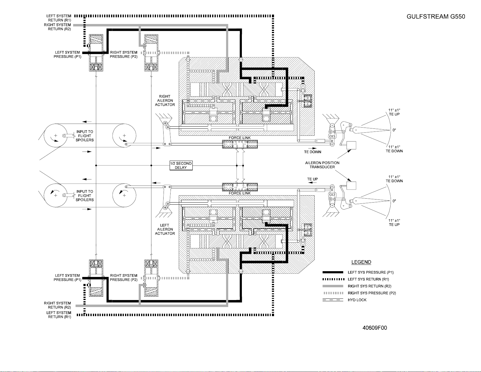
Each hydraulic actuator is powered by both hydraulic systems. The
actuators have a central shaft surrounded by a dual piston chamber. Each
chamber is powered by a dedicated left or right hydraulic system. The
pistons are moved by hydraulic pressure ported to the extend or retract
sides of the chamber by control valves moved by the aileron cable linkage.
The pistons extend or retract the central shaft of the actuator that in turn
moves a bellcrank and linkage to position the aileron. A mechanical
linkage, termed a force link, between the control cable input to the actuator
and the output of the actuator to the aileron parallels actuator operation
and provides the sensing element for operation of the HOPS provision.
Loss of a single hydraulic system will not degrade aileron activation since
the remaining system is capable of providing sufficient power for a full
range of aileron displacement. See the illustration of the linkages and
actuators in Figure 11.
B. Aileron Control Disconnect:
If a malfunction causes one of the ailerons to become inoperative, the
mechanical link between the two cockpit control yokes can be separated to
allow independent operation of the normally functioning aileron. A handle
on the right side of the cockpit center pedestal, labelled AIL DISC is
connected to a pin in the mechanical linkage. (See Figure 12). Pulling up
on the handle retracts the pin mating the two yokes and allows full control
of the operative aileron. If the flight crew is unable to exert sufficient force
PRODUCTION AIRCRAFT SYSTEMS 2A-27-00
Page 37
August 14/03
Page 38

OPERATING MANUAL
Title Page
Prev Page
Next Page
TOC
to retract the pin, a trigger mechanism beneath the handle can be activated
to supply additional gas cartridge pressure to assist in retracting the pin. If
the cartridge assist is used, the aileron channel linkage cannot be
reconnected in flight since it requires special maintenance tools. However,
if only manual force is used to disconnect the aileron channels, the pin may
be reinserted in the mechanical arm link by pushing in on the handle if it is
determined that the malfunctioning aileron has returned to normal
operation.
C. Aileron Hard Over Prevention System (HOPS):
The conformity of the motion of aileron hydraulic actuators to aileron
control inputs from cockpit yokes or the autopilot is monitored by force link
mechanisms. The force links are the sensing elements that initiate aileron
HOPS activation. (See the flight controls HOPS system diagram in Figure
3). The mechanisms are essentially telescoping tubes with two sections one section that travels within the other. The end of one section of the tube
is connected to the cable linkage control inputs to the hydraulic actuator
and the end of the other tube section of the is connected to the actuator
shaft output to the aileron. The dual tube mechanism thus parallels the
action of the aileron actuator. Each tube section is spring loaded to resist
the push and pull motion transmitted through the actuator to move the
aileron. If a control cable input to the actuator is in the push direction and
the actuator shaft does not transmit a push assist or the aileron does not
move, the spring at the push end of the force link tube is compressed, and
an electrical contact within the spring initiates a signal to the hydraulic
control valves of both left and right aileron hydraulic actuators to bypass
system pressure. (If a resistance to control link input is present in the pull
direction, the spring and electrical contact at the end of the other section
would operate in the same way to activate HOPS bypass of hydraulic
pressure.)
The electrical signal incorporates a one half (½) second delay before
activating the hydraulic pressure bypass. Once activated, the control
valves are latched to the bypass position. If, in the judgement of the flight
crew, the condition causing the malfunction is transient, and the use of the
ailerons is deemed essential to continued safe flight and landing, the
HOPS initiated bypass can be reset by cycling both the LEFTAIL HYD S/O
and RIGHT AIL HYD S/O circuit breakers. If the malfunction is still present
the control valves will re-latch to the bypass state after the one half (½)
second delay.The left aileron shut off valve is powered by the left essential
DC bus and the right aileron shut off valve by the right essential DC bus.
When the electrical signal bypasses hydraulic pressure to the actuators,
signals are also sent to Input / Output (I/O) modules in the Modular
Avionics Units (MAUs). The left aileron state is communicated to MAU #1
and the right aileron state to MAU #2. The MAUs communicate with the
Monitor and Warning System (MWS) that formats the appropriate
messages for presentation on the Crew Alerting System (CAS) window.
To prevent inadvertent HOPS bypass of the aileron actuators during flight
conditions requiring quick reversals of the ailerons, the actuation of the
HOPS is filtered by:
• The compression of the springs within the force link sections
• Inertia in hydraulic piston action
Page 38
August 14/03
PRODUCTION AIRCRAFT SYSTEMS2A-27-00
Page 39

OPERATING MANUAL
Title Page
Prev Page
Next Page
TOC
• The one half (½) second electrical delay
D. Aileron Position Sensing:
The position of each aileron is sensed by a Rotary Variable Displacement
Transducer (RVDT). The RVDTs are installed at the hinge point of the
ailerons, and transmit an electrical signal proportional to the displacement
of the aileron from the neutral position. The signals are communicated to
the autopilot processor modules in the MAUs where, in conjunction with the
Actuator Input / Output Processors (AIOPs), autopilot commands are
formulated for the electric servos in the cable control linkage for the
ailerons. The MAUs also provide aileron position information to the MWS
for generation of the graphic display of control surface position on the Flight
Controls 2/3 synoptic page.
E. Aileron Trim System:
(See Figure 12.)
Only one trim tab is installed for both ailerons, since both the left and right
ailerons work in symmetrically opposite directions through the cable
linkage and mechanical arm connecting both control yokes. The trim tab is
located on the left aileron and is made of carbon epoxy fabric. The aileron
trim tab is a manually operated by cable linkage from the aileron trim wheel
on the aft section of the cockpit center pedestal to the trim tab bellcrank
actuator. Moving the trim wheel to the left positions the trim tab down into
the airstream, deflecting the left aileron up to reduce lift on the left wing,
moving the wing downward. At the same time the connecting linkage
moves the right aileron down to increase lift on the right wing and move the
wing up. The range of travel for the aileron trim tab is 15 degrees up or
down.
The aileron trim tab actuator has ceramic element that is heated to prevent
the actuator from freezing. The actuator is maintained at a constant
temperature of 175°±20°F. The heater is controlled by the AIL TRIM HEAT
circuit breaker on the Right Electronic Equipment Rack (REER) and
receives power from the right main AC bus.
The trim tab is also equipped with a RVDT to provide information to MAU
#1 for the autopilot processor and the MWS for graphic display on synoptic
and system windows.
F. Flight Spoiler Roll Augmentation:
The aircraft is equipped with three spoiler panels on the top surface of each
wing, just forward of the flaps. The spoiler panels are rectangular in shape
and are hinged at the forward edge to allow the panels to pivot upward, into
the airflow over the wing to disrupt lift. The spoiler panels are hydraulically
powered by actuators supplied with three thousand (3,000) psi pressure
from both hydraulic systems. Loss of one hydraulic system will not effect
spoiler operation since a single system supplies sufficient pressure for full
spoiler activation. The spoilers serve three functions:
• As speed brakes, all six spoilers (three on each wing) are extended
to disrupt airflow over the wing and decrease lift in order to slow the
aircraft and/or increase descent rates
• On landing, with weight on the wheels, all six panels (three on each
wing) extend to provide aerodynamic drag to aid in slowing the
aircraft
PRODUCTION AIRCRAFT SYSTEMS 2A-27-00
Page 39
August 14/03
Page 40
OPERATING MANUAL
Title Page
Prev Page
Next Page
TOC
• As flight spoilers, only the two outboard spoilers on each wing (a
total of four spoiler panels) can be used in conjunction with the
ailerons to increase the rate of roll of the aircraft
Flight spoilers deploy upward on the side of the upward displaced aileron to
contribute to the decrease in lift on the downward rolling wing. By
interrupting additional airflow over the wing on the inside of a turn, roll rate
into the turn is increased. Spoilers are activated by the same cable linkage
that controls aileron deployment. A bellcrank in the aileron cables on the aft
wing beam provides an input to a mixing and summing series of pushrods
and hinges to provide a mechanical command to the hydraulic actuator for
the two outboard spoiler panels.
The amount of flight spoiler extension is proportional to aileron
displacement. Maximum aileron displacement is eleven degrees (11°) from
neutral and maximum flight spoiler extension is forty-seven degrees (47°)
up from the faired position. The following table shows examples of the
aileron / flight spoiler displacement ratio:
Aileron Displacement Flight Spoiler Extension
Up one half degree (+½°) Up one half degree (+½°)
Up one degree (+1°) Up five and one half degrees (+5.5°)
Up seven degrees (+7°) Up twenty-eight degrees (+28°)
Up eleven degrees (+11°) Up forty-seven degrees (+47°)
If the spoilers are in use as speed brakes, all three spoiler panels on each
wing can be extended up to thirty degrees (30°) with commands from the
speed brake control handle on the cockpit center pedestal. If a turn is
initiated with speed brakes extended, the two outboard spoiler panels on
the downward rolling wing will extend an additional amount up to fifty-five
degrees (55°) to increase the roll rate into the turn.
Malfunctions in the spoiler system are controlled by selecting the spoilers
off. There is no manual extension provision for spoilers. A SPOILER
CONTROL pushbutton is installed in the cockpit center pedestal just
forward of the speedbrake handle, as shown in Figure 12. Pushing the
button in will bypass all hydraulic pressure to the spoilers and illuminate the
amber OFF legend on the face of the button.
3. Controls and Indications:
(See Figure 12.)
NOTE:
A full description of the Flight Controls 2/3 synoptic
page appears in section 2B-07-00.
A. Circuit Breakers (CBs):
The following circuit breakers protect the aileron and flight spoiler roll
controls:
Circuit Breaker Name: CB Panel: Location: Power Source:
LEFT AIL HYD S/O POP C-4 L ESS DC Bus
RIGHT AIL HYD S/O CPOP C-4 R ESS DC Bus
PRODUCTION AIRCRAFT SYSTEMS2A-27-00
Page 40
August 14/03
Page 41
OPERATING MANUAL
Title Page
Prev Page
Next Page
TOC
Circuit Breaker Name: CB Panel: Location: Power Source:
SPLR FLT PWR S/O CPOP E-3 R ESS DC Bus
AIL TRIM HEAT REER D-16 R MAIN AC Bus
B. Crew Alerting System (CAS) Messages:
The following CAS messages are associated with the roll flight controls
system:
Area Monitored: CAS Message: Message Color:
L / R Aileron Hydraulic Actuators L - R Aileron Hydraulics
Off
Amber
Spoiler Control Switch Spoilers Hydraulic Off Amber
Aileron Trim Tab RVDT and
Autopilot Aileron Servos
Aileron Trim Tab RVDT and
Autopilot Aileron Servos
Retrim Left Wing Down Amber
Retrim Right Wing Down Amber
4. Limitations:
There are no limitations established for the aileron roll control system at the time
of this writing.
PRODUCTION AIRCRAFT SYSTEMS 2A-27-00
Page 41
August 14/03
Page 42

OPERATING MANUAL
Title Page
Prev Page
Next Page
TOC
THIS PAGE IS INTENTIONALLY LEFT BLANK.
Page 42
August 14/03
PRODUCTION AIRCRAFT SYSTEMS2A-27-00
Page 43
OPERATING MANUAL
Title Page
Prev Page
Next Page
TOC
Aileron Linkage and
Actuators
Figure 11
2A-27-00
Page 43 / 44
August 14/03
Page 44

Title Page
Prev Page
Next Page
TOC
Page 45
OPERATING MANUAL
Title Page
Prev Page
Next Page
TOC
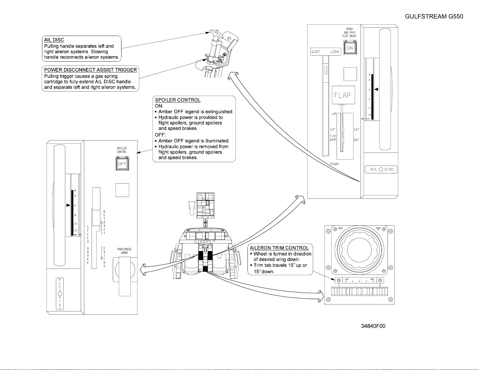
Aileron and Spoiler
Controls and Indications
Figure 12
2A-27-00
Page 45 / 46
August 14/03
Page 46

Title Page
Prev Page
Next Page
TOC
Page 47

OPERATING MANUAL
Title Page
Prev Page
Next Page
TOC
2A-27-50: Horizontal Stabilizer and Wing Flaps
1. General Description:
The aircraft horizontal stabilizer is mounted at the top of the vertical stabilizer.The
horizontal stabilizer is movable in order to provide a flexible aircraft neutral
stability position in the pitch axis as flaps are extended or retracted. As the flaps
extend they effectively produce a large change in the wing airfoil. The airfoil
change moves the center of lift aft, causing a nose down moment in the pitch axis.
The horizontal stabilizer will automatically compensate for pitch changes as the
flaps extend by moving leading edge down, moderating elevator trim change and
conserving elevator deflection for landing. As flaps are retracted, the stabilizer
moves leading edge up to reduce elevator forces as the wing center of lift transits
forward.
The Fowler-type flaps installed on the trailing edge of each wing provide the
additional lift required to fly at slower airspeeds. By extending aft and down, the
flaps change airflow over the wing, effectively lengthening wing chord and
increasing wing thickness. By emulating a larger wing surface, the flaps decrease
takeoff and landing speeds.
2. Description of Subsystems, Units and Components:
A. Horizontal Stabilizer and Actuator
The horizontal stabilizer is an all-metal structure mounted to the top of the
vertical stabilizer at two points. The aft point consists of a shaft installed
through an opening allowing the stabilizer to pivot. The front attachment is
an electrically powered jackscrew that moves the leading edge of the
stabilizer up and down. The range of movement available for the horizontal
stabilizer is 1.25°up to 4.6°down. The jackscrew is driven by an electric
actuator with two motor windings, and incorporates a locking ratchet
mechanism that prevents movement of the stabilizer if there is no electrical
input to the AC drive motor. The two AC motor windings are independently
powered by the left and right standby AC buses that can be energized by
the Hydraulic Motor Generator (HMG) in the event of electrical failure.
Each AC motor winding has an independent essential DC bus powered
control channel for increased redundancy. (The horizontal stabilizer is fully
operational using a single motor and control channel.) A Rotary Variable
Displacement Transducer (RVDT) is mounted on the actuator to provide
feedback to control signals and to furnish position information for display
on the Flight Controls 2/3 synoptic page and on the Horizontal Situation
Indicator (HSI) portion of the Primary Flight Director (PFD). Stabilizer
position data is communicated to MAU #1 and #2 through ARINC-429 bus
connections from the Flap Control Unit (FCU) where it is shared with the
Monitor and Warning System (MWS).
NOTE:
The CrewAlerting System (CAS) messages generated
by the MWS use the following convention to denote
the redundant power and control sources for the
operation of the horizontal stabilizer:
• Stabilizer channel A = left standby AC power and
left essential DC control
• Stabilizer channel B = right standby AC power and
PRODUCTION AIRCRAFT SYSTEMS 2A-27-00
Page 47
August 14/03
Page 48

OPERATING MANUAL
Title Page
Prev Page
Next Page
TOC
right essential DC control
Control inputs to drive the actuator come from two (2) sources:
(1) The Flap / Horizontal Stabilizer Control Unit (FCU) to compensate
for flap extension.
(2) Pilot or Copilot yoke trim switches in the Emergency Stabilizer mode
to provide aircraft pitch control if the elevators malfunction or jam.
All control inputs to move the horizontal stabilizer are routed through the
Flap Control Unit (FCU) that coordinates stabilizer position with aircraft
configuration. The FCU prioritizes control inputs to the stabilizer AC motors
so that:
• The stabilizer position schedule is matched to flap position
• Arming the Emergency Stabilizer cancels all other stabilizer
operating modes
Other control and coordination functions of the FCU are discussed in the
following wing flap section - the position of the stabilizer is scheduled by
wing flap extension settings to allow the greatest range of elevator
effectiveness for takeoffs and landings.
If the elevators become jammed or otherwise malfunction, selecting the
EMERG STAB pushbutton switch (shown in Figure 14) to ARM (the
pushbutton legend will illuminate amber) enables the trim switches on the
pilot and copilot yokes to control the position of the stabilizer. As soon as
the yoke trim switch is moved in either direction, the FCU isolates the
stabilizer from all other command inputs. The yoke trim switches can then
be used for a reduced amount of pitch control during flight and landing.
The emergency stabilizer mode is communicated from the FCU to the
Flight Management System (FMS) Actuator Input / Output Processor
(AIOP) modules in MAU #1 and #2 and the MWS processors in MAU #1,
#2 and #3. The MWS initiates the display of a CAS message indicating
emergency stabilizer operation and provides the stabilizer position display
on the Flight Controls 2/3 synoptic page and HSI on the PFD.
B. Flap Control Unit (FCU) and Horizontal Stabilizer Operation:
The Flap and Stabilizer Controller, most often termed the Flap Control Unit
(FCU) is located in the Baggage Compartment Electronic Equipment Rack.
The FCU is a processor that receives external position commands for the
flaps and horizontal stabilizer and also internally computes position
commands for the horizontal stabilizer to coordinate stabilizer position with
flap position. External commands for the flaps are initiated by the flap lever
in the cockpit, and external stabilizer commands are sourced from the
electric trim switches when the emergency stabilizer mode is selected. The
FCU responds to position commands for the flaps and stabilizer by
providing dual channel DC control signals to position the flaps and dual
channel DC control and AC actuator power to move the stabilizer to
commanded positions. A block diagram of the Flap / Stabilizer Controller
(or FCU) is shown in Figure 13.
Flap position commands are obtained from two RVDTs on the cockpit flap
control lever.The FCU compares the commanded position with the existing
flap position derived from RVDTs on each wing flap. If there is a difference
in the two positions, the FCU signals operation of the Power Drive Unit
(PDU) that hydraulically actuates the flaps to the commanded position.
Page 48
August 14/03
PRODUCTION AIRCRAFT SYSTEMS2A-27-00
Page 49
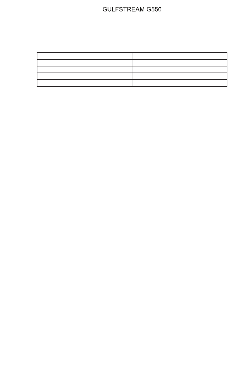
OPERATING MANUAL
Title Page
Prev Page
Next Page
TOC
(The operation of the aircraft flaps is described in the following sections.)
The FCU moves the horizontal stabilizer to compensate for the change in
the center of lift on the wing as flaps are extended. The FCU processor
schedules stabilizer position according to the following table:
Flap Position Horizontal Stab Position
0° (flaps up) −1.5° ±.1°
10° −2.7° ±.1°
20° −3.6° ±.1°
39° (flaps down) −4.6° ±.1°
If a malfunction such as a flap asymmetry prevents the flaps from moving,
the FCU cancels movement of the horizontal stabilizer. The horizontal
stabilizer remains operative in the EMER STAB mode, and can be
positioned with the cockpit yoke trim switches.
If the EMER STAB mode is used to control the horizontal stabilizer, and
subsequently control of the horizontal stabilizer is returned to normal
operation (by deselecting theARM state with the EMER STABpushbutton),
the FCU will move the stabilizer to align with the existing flap setting
according to the processor internal schedule. During this process, an
advisory (blue) CAS message of “Stabilizer Syncing A - B” will be
displayed.
C. Wing Flaps:
A Fowler-type flap is installed on the trailing edge of each wing. Fowler
flaps, when extended, move aft and down from the wing trailing edge,
increasing wing area to generate additional lift for low speed flight. Fowler
flaps have a cross-section similar to wing airfoils, and by deploying aft of
the wing trailing edge, open up a gap between the wing and flap allowing
additional airflow over the flap. RVDTs are installed on the outer section of
the flaps to provide position feedback information to the FCU.
Flap extension and retraction is controlled with the flap handle on the
copilot side of the center console, shown in Figure 16. Each flap extends
back from the wing along four tracks with rollers attached to the flaps
moving within the tracks. The two middle track installations on each wing
also contain the jackscrews that extend or retract the flaps. The jackscrews
on each wing are driven by torque tubes installed on the aft section of the
wing running inboard to a hydraulic Power Drive Unit (PDU) located in the
main landing gear wheel well. The PDU is powered by the left hydraulic
system and uses a gearbox to transmit hydraulic pump rotation to the
torque tubes. If the left hydraulic system is not available due to a
malfunction, the auxiliary (AUX) hydraulic pump or the Power Transfer Unit
(PTU) can be used to pressurize left hydraulic system fluid to operate the
PDU. A schematic of the wing flaps system operation is shown in Figure
15.
The direction of PDU rotation is controlled by two solenoid valves, one to
extend the flaps and the other to retract the flaps. Each solenoid valve has
dual control channels (A and B) from the FCU. The FCU compares the
position of the RVDTs on the flap handle in the cockpit to the position
indicated by the flap RVDTs, and signals the extend or retract solenoid
valve on the PDU, powering the PDU in the required direction to extend or
PRODUCTION AIRCRAFT SYSTEMS 2A-27-00
Page 49
August 14/03
Page 50

OPERATING MANUAL
Title Page
Prev Page
Next Page
TOC
retract the flaps.
Incorporated into the flap jackscrew actuators are force limiters that
prevent structural damage to the flaps from high airspeeds. If the flaps are
selected to a setting greater than that allowed by airspeed limits, the force
limiters will brake the motion of the jackscrews, preventing further
extension of the flaps (the jackscrews will continue to attempt to turn, but
are unable to overcome the force limiters). During the overspeed condition,
the flaps will operate in the opposite direction if retracted to a lower setting.
If the flaps are not retracted, the force limiters will release once airspeed
drops below the limit for the selected flap setting.
NOTE:
If airspeed exceeds the limit for the current flap
setting, the overspeed condition will be signalled by
the change in color of the airspeed tape on the PFD
and the OVERSPEED aural clacker will sound over
cockpit speakers.
D. FCU and Flap Operation:
The FCU uses RVDT data from the flap handle and flap position to drive
the PDU in the correct direction to extend or retract the flaps. The FCU also
uses flap handle RVDT data to position the horizontal stabilizer in the
correct position according to the schedule corresponding to flap position.
The FCU processor software also monitors performance of the flaps,
horizontal stabilizer and flap / stabilizer scheduled positions. If a fault is
detected, the operation of the malfunctioning unit (flaps or stabilizer) is
interrupted and through ARINC-429 connections to the MAUs, the MWS
generates the display of the appropriate CAS message(s). For instance, if
the FCU detects an asymmetry during the extension of the two wing flaps,
the FCU stops operation of the PDU and signals the condition to the MWS
through the MAUs. The MWS generates an amber “Flap Asymmetry”
caution message on the CAS display.(The complete list of CAS messages
pertaining to flap and horizontal stabilizer operation are shown at the end of
this section.)
Flap RVDT reported position is supplied by the FCU to open or close a
relay at a flap setting of twenty-two degrees (22°). The relay provides the
flap position input for the configuration warning horn of the landing gear
control system. The landing gear warning horn will sound if:
• Power levers at idle, flaps extended less than 22°, landing gear not
down and altitude less than three hundred fifty feet (350 ft.)
• Power levers at any setting, flaps extended more than 22° and
landing gear not down
The FCU is used to perform maintenance functions involving recalibration
of wing flap position to flap handle position and horizontal stabilizer position
to flap position. The maintenance process uses selector switches on the
face of the FCU to perform the recalibration. Various CAS messages will be
displayed during the maintenance procedure, and are included in the list at
the end of this section for information only.
Page 50
August 14/03
PRODUCTION AIRCRAFT SYSTEMS2A-27-00
Page 51
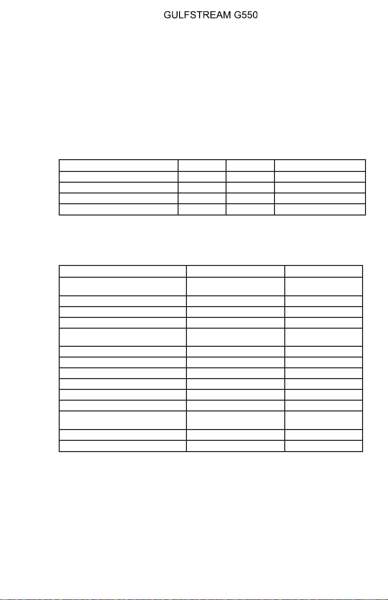
OPERATING MANUAL
Title Page
Prev Page
Next Page
TOC
3. Controls and Indications:
(See Figure 14.)
NOTE:
A full description of the Primary Flight Display appears
in section 2B-05-00 and a description of the Flight
Controls 2/3 synoptic page appears in section 2B-07-
00.
A. Circuit Breakers (CBs):
The following CBs protect the horizontal stabilizer system:
Circuit Breaker Name: CB Panel: Location: Power Source:
FLAP/STAB LEFT DC POP C-6 L Essential DC Bus
FLAP/STAB RIGHT DC CPOP C-6 R Essential DC Bus
FLAP/STAB L STBY AC POP D-2 L Standby AC Bus
FLAP/STAB R STBY AC CPOP D-2 R Standby AC Bus
B. Crew Alerting System (CAS) Messages:
The following CAS messages are associated with the horizontal stabilizer
system:
Area Monitored: CAS Message: Message Color:
EMER STAB Switch / Stabilizer
Motor Channels
Emergency Stabilizer On
A-B
Amber
Flap Control Unit Flap Asymmetry Amber
Flap Control Unit Flap Command Invalid Amber
Flap Control Unit Flaps Failed Amber
Flap Control Unit
Flap/Stab IndependentOpAmber
Flap Control Unit Flap/Stab Miscompare Amber
Flap Control Unit Flap/Stab Sync Fail Amber
Flap Control Unit Stabilizer Failed Amber
Flap Control Unit Uncommanded Flaps Amber
Flap Control Unit Uncommanded Stabilizer Amber
Flap Control Unit Flap/Stab Maint Reqd A-B Blue
Flap Control Unit
Flap/Stab System Fail
A-B
Blue
Flap Control Unit Flap/Stab Rig Complete Blue
Flap Control Unit Stabilizer Syncing A-B Blue
4. Limitations:
Flap Altitude and Airspeed Limits:
• Maximum operating altitude for extending landing flaps (39° DOWN) or
flying with landing flaps extended is 20,000 ft MSL
• Maximum operating altitude for extending flaps to 10° or 20° or flying with
the flaps extended to 10° or 20° is 25,000 ft MSL
• Maximum airspeed for flaps extended to 10° is 250 KCAS / 0.60 M
T
PRODUCTION AIRCRAFT SYSTEMS 2A-27-00
Page 51
August 14/03
Page 52

OPERATING MANUAL
Title Page
Prev Page
Next Page
TOC
• Maximum airspeed for flaps extended to 20° is 220 KCAS / 0.60 M
• Maximum airspeed for flaps extended to 39° is 170 KCAS / 0.60 M
T
T
Use of Flaps:
Use of flaps in icing conditions is restricted to takeoff, approach and landing only.
Holding in icing conditions is limited to 0° flaps only.
Emergency Stabilizer Trim:
Maximum airspeed with the emergency stabilizer armed with the autopilot
engaged and a jammed elevator is 270 KCAS / M.80.
Page 52
August 14/03
PRODUCTION AIRCRAFT SYSTEMS2A-27-00
Page 53
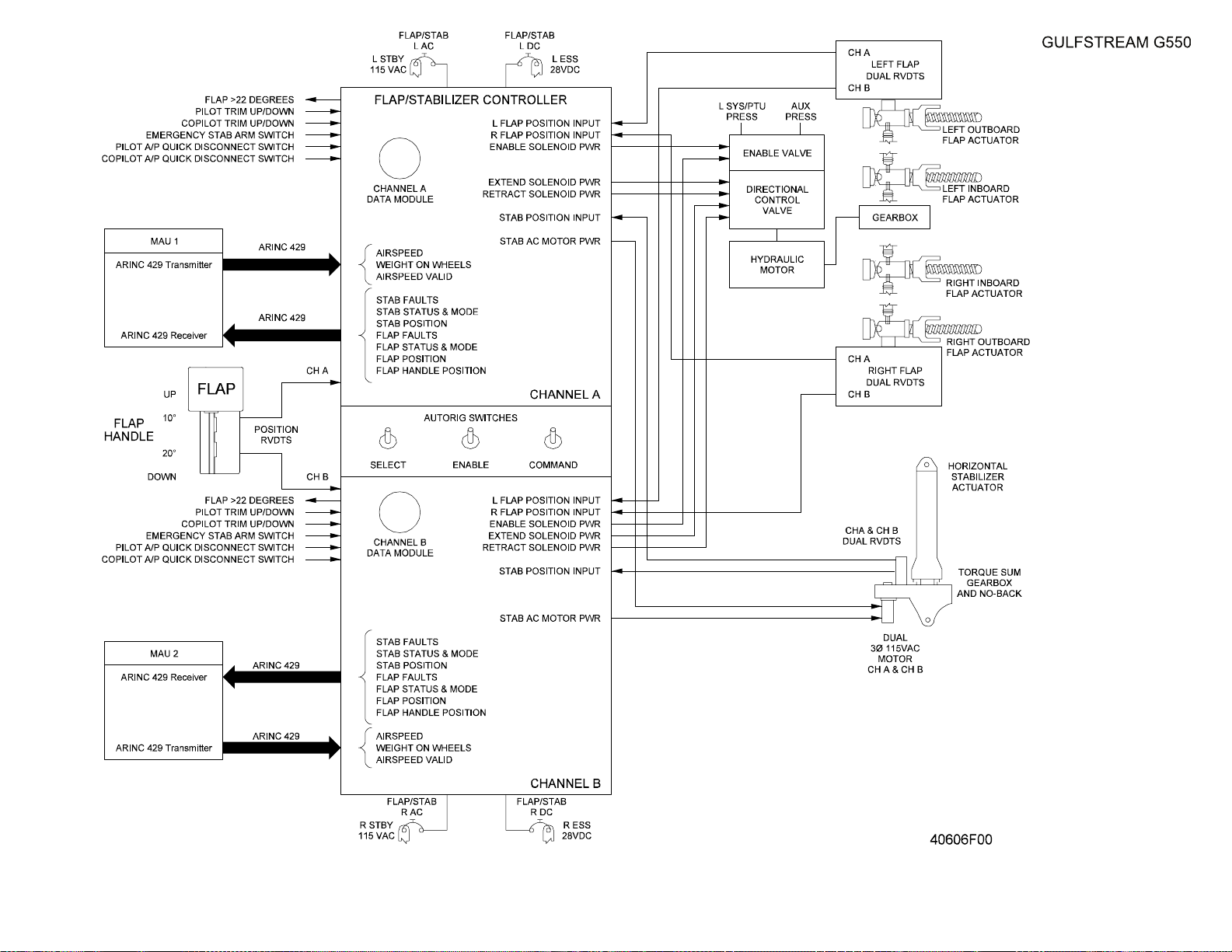
OPERATING MANUAL
Title Page
Prev Page
Next Page
TOC
Flap / Horizontal Stabilizer
System Block Diagram
Figure 13
2A-27-00
Page 53 / 54
August 14/03
Page 54

Title Page
Prev Page
Next Page
TOC
Page 55
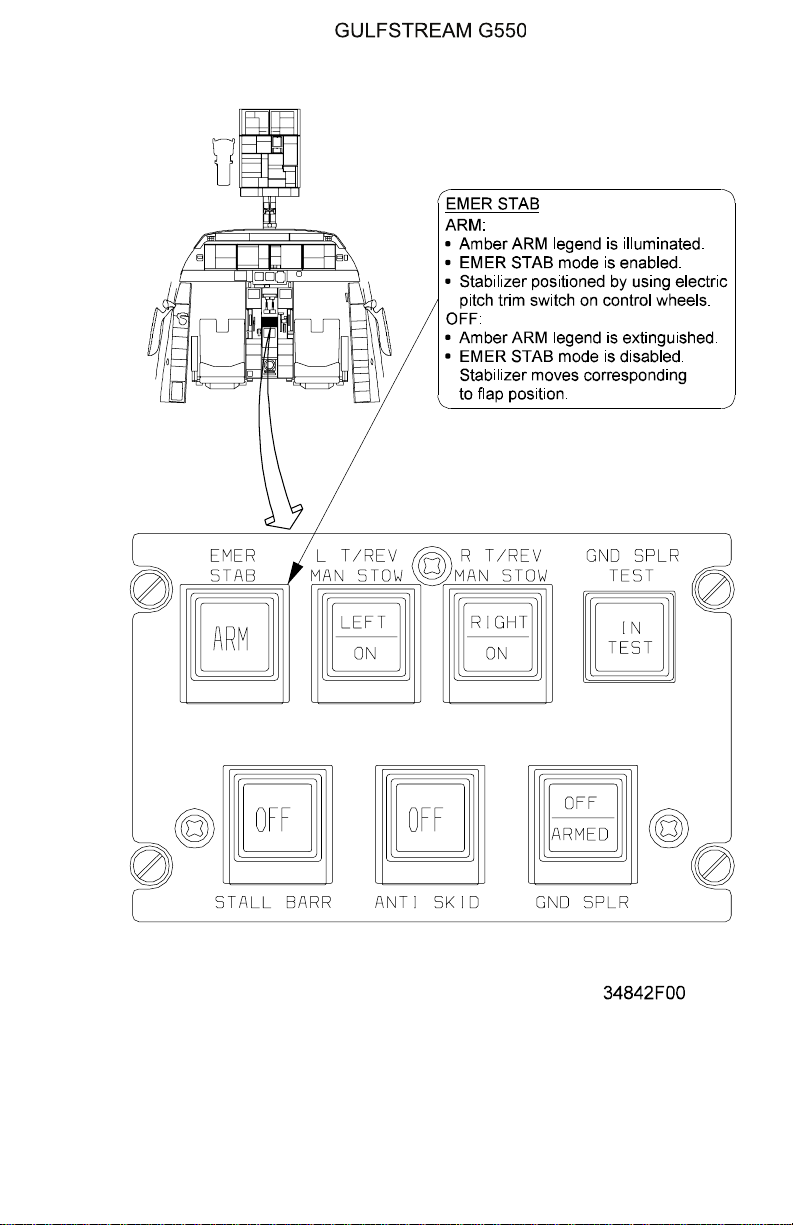
OPERATING MANUAL
Title Page
Prev Page
Next Page
TOC
Horizontal Stabilizer System Controls and Indications
Figure 14
PRODUCTION AIRCRAFT SYSTEMS 2A-27-00
Page 55
August 14/03
Page 56

OPERATING MANUAL
Title Page
Prev Page
Next Page
TOC
THIS PAGE IS INTENTIONALLY LEFT BLANK.
Page 56
August 14/03
PRODUCTION AIRCRAFT SYSTEMS2A-27-00
Page 57
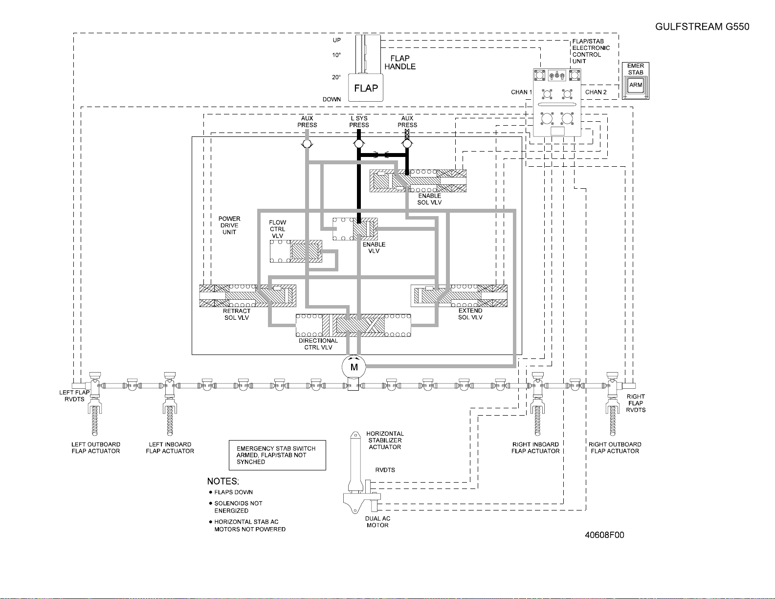
OPERATING MANUAL
Title Page
Prev Page
Next Page
TOC
Wing Flaps System
Figure 15
2A-27-00
Page 57 / 58
August 14/03
Page 58

Title Page
Prev Page
Next Page
TOC
Page 59
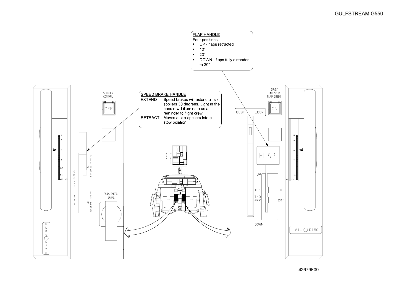
OPERATING MANUAL
Title Page
Prev Page
Next Page
TOC
Flap Handle
Figure 16
2A-27-00
Page 59 / 60
August 14/03
Page 60

Title Page
Prev Page
Next Page
TOC
Page 61

OPERATING MANUAL
Title Page
Prev Page
Next Page
TOC
2A-27-60: Stall Warning and Prevention System (SWPS)
1. FAA Certified Airplanes Versus JAA Certified Airplanes:
In some instances, the Stall Warning and Prevention System (SWPS) differs
between FAAcertified airplanes and JAA certified airplanes. This section presents
a description of the system installed in FAA certified airplanes. A synopsis of the
differences for JAA certified airplanes is presented in the Limitations portion of
this description.
2. General Description:
The SWPS provides the flight crew with visual indications of deteriorating
airspeed and high angles of attack, a physical warning of an impending stall by
activation of a yoke stick shaker and automatic elevator flight control movement
by a stick pusher to decrease angle of attack.
The SWPS functions are hosted in the autopilot (AFCS) processor modules of
Modular Avionics Units (MAUs) #1 and #2. Since each MAU autopilot module is a
fully-redundant independent processor, the SWPS is also a redundant system,
with each MAU using separate data inputs from Angle of Attack (AOA) sensors,
Flap Control Unit (FCU) channels, Inertial Reference Systems (IRSs), Air Data
Systems (ADS) and Display Controllers (DCs). Each MAU also has independent
outputs through Actuator Input/Output Processors (AIOPs) to separate channels
for the yoke stick shakers and hydraulic actuator valves of the yoke stick pusher.
A schematic of the system is contained in Figure 17.
Operation of the SWPS is controlled by the STALL BARR switch on the cockpit
center console. The SWPS must be operative prior to commencing flight, and the
switch is required to be selected on for all flight operations unless a malfunction
occurs during flight. (See Figure 18.)
3. Description of Subsystems, Units and Components:
A. Angle of Attack (AOA) Sensors:
Because an aircraft stall is an aerodynamic condition caused by separation
of the boundary layer of airflow over the wing at high angles of attack, AOA
data is more accurate than airspeed in determining the onset of a stall.
Airspeed is closely related to AOA, but is subject to indication and
compressibility errors - however, since airspeed is the standard reference
used by flight crews to control angle of attack, the airspeed indication
displayed on the Primary Flight Display (PFD) provides the best cues to the
onset of a stall condition. Angle of attack is included on the PFD, but in an
abbreviated format.
Two AOA sensors are installed on the G550, one on each side of the
aircraft positioned below and aft of the pilot and copilot windows. The AOA
sensors are powered and heated by the respective side essential DC bus
(left AOA by left essential DC bus, etc.). The AOA sensors are vanes that
measure the relative wind generated by the aircraft flight path. Each AOA
vane is mounted on a shaft that allows the vane to rotate, aligning the vane
into the relative wind. The amount of vane rotation is measured internally
by the AOA sensor and transmitted over ARINC-429 connections to the
MAUs (the left AOA sensor to MAU #1, right AOA sensor to MAU #2). The
SWPS function of the AFCS modules in the MAUs compare the relative
wind data with effective chord of the aircraft wing to determine the aircraft
angle of attack.
The effective chord of the wing changes with flap extension and is sensed
PRODUCTION AIRCRAFT SYSTEMS 2A-27-00
Page 61
August 14/03
Page 62

OPERATING MANUAL
Title Page
Prev Page
Next Page
TOC
by the SWPS function through the dual channels of the Flap Control Unit
(FCU). Position of each wing flap is reported by Rotary Variable
Displacement Transducers(RVDTs)to the respective FCU control channel.
Each of the FCU channels is connected over ARINC-429 links to the
MAUs. The SWPS software is programmed with a set of AOA values for
each flap setting, and triggers stall warning and prevention measures if the
values are exceeded.
To ensure that the AOA values used by the SWPS are the most accurate
possible, each MAU processor filters the input AOA data using time
averaging and compares inputs with the AOA data from the other MAU
processor and also with IRS pitch, roll, acceleration, change rates and True
Air Speed (TAS) a final refined AOA value.
Since the display of actual AOA would not be meaningful to the flight crew
due to the change in significance of the values with flap setting, the
software in the SWPS computes a normalized value for AOA. The
normalized value uses a format of zero (0) to one (1) with the indication
shown to two (2) decimal places, where 0.00 indicates zero lift on the wing
and 1.00 indicates the point of maximum wing lift. A normalized AOA value
of 1.00 is also the threshold of stick pusher activation, since any further
increase in AOA above the maximum lift angle results in a stall. The
normalized AOA value is displayed on the PFD below the airspeed tape.
B. Low Airspeed Indications:
The airspeed and AOA indications on the PFD provide the flight crew with
visual indications of deteriorating airspeed and high angles of attack. As
airspeed slows, the stick shaker threshold point is shown beside the
airspeed tape as a red bar descending with airspeed from the shaker
initiation point. If airspeed is slowing at a rate that will soon reach the
shaker initiation speed, the airspeed trend vector indicator will change to
amber. If airspeed reaches the stick shaker threshold, the digital airspeed
readout and AOA display will change to amber. Further airspeed loss that
initiates activation of the stick pusher is denoted by the digital airspeed and
AOA displays changing to red.
C. Yoke Stick Shakers:
Each cockpit yoke is equipped with an electrically powered stick shaker
installed under the flight deck floor. The motor for the pilot stick shaker is
powered by the left essential DC bus; the copilot shaker is powered by the
right main DC bus. The pilot yoke stick shaker is controlled by the SWPS
function in MAU #1 and the copilot stick shaker by MAU #2. The SWPS
software function activates the stick shakers at a threshold that provides
adequate margin for pilot action to avoid a stall. The stick shaker activation
point is set at:
• A normalized AOA value of 0.90 for the first six (6) seconds after
takeoff (weight off wheels) to prevent nuisance activations
• A normalized AOA value of 0.85 thereafter for all flap settings
These stick shaker thresholds provide at least a ten percent (10%)
airspeed margin prior to stick pusher activation and stall onset. Once the
stick shakers have been triggered, only a decrease in AOA below the
activation point will turn off the stick shakers. If a stick shaker malfunctions
and activates below the normalized AOA trigger threshold, the circuit
Page 62
August 14/03
PRODUCTION AIRCRAFT SYSTEMS2A-27-00
Page 63

OPERATING MANUAL
Title Page
Prev Page
Next Page
TOC
breaker for the faulty stick shaker can be pulled (SHAKER #1 on the pilot
overhead panel, SHAKER #2 on the copilot overhead panel).
The MAUs monitor their respective data input paths and SWPS activation
paths for operational capabilities. If faults or failures are found, the status is
reported to the Monitor and Warning System (MWS) that will in turn
generate appropriate CAS messages for flight crew notification.
D. Yoke Stick Pusher:
If the visual display of low airspeed and high AOA in conjunction with
activation of the cockpit yoke stick shakers does not prompt a decrease in
AOA and airspeed gain, the SWPS function of the autopilot processors will
command the aircraft elevators to a nose down position in an attempt to
avoid stalling the aircraft wing. If the aircraft approaches a normalized AOA
of 1.00, each SWPS channel will separately signal activation of a dedicated
hydraulic solenoid valve on the stick pusher mechanism in the tail
compartment. The stick pusher mechanism is installed just aft of the dual
elevator hydraulic actuators, and employs a linkage connected by a cam
arm to provide a nose down movement to the input side of the elevator
actuators. Activation of the stick pusher will not interrupt the action of the
stick shakers.
The SWPS software provides an anticipatory function for the stick pusher,
so that at lower airspeeds, stick pusher activation will respond to the rate of
change in aircraft body angle (as sensed by the IRS) to prevent the aircraft
from overshooting the 1.00AOA stall point. As airspeed increases from .76
Mach to .80 Mach the anticipatory function is biased out of the activation
logic, since large control inputs are not necessary at high airspeeds.
The stick pusher will deactivate the nose down input to the elevators when
aircraft acceleration drops below 0.5 G or the actual wing AOA decreases
3.6° below the stick pusher activation threshold.
If a malfunction causes a spurious activation of the stick pusher, a manual
force on the control column of approximately seventy-five pounds (75 lbs)
will overcome the nose down control input. The stick pusher may be
electrically disconnected by depressing either of the pilot or copilot yoke
A/P DISC BARR DISC switches or by selecting the STALLBARR switch on
the cockpit center pedestal to off (the OFF legend in the pushbutton switch
will illuminate amber). Normally the yoke switches are used if the crew is
hand flying the aircraft and the pedestal pushbutton is used during
autoflight to avoid disconnecting the autopilot.
The MAUs monitor the performance of the data inputs used to activate the
stick pusher and the health of the stick pusher hydraulic actuation
installation. Any degraded performance is annunciated to the crew through
MWS initiated CAS messages.
E. SWPS Ground Test:
Although the stall warning and prevention system does not operate with the
aircraft on the ground (weight on wheels), a preflight test of the system may
be conducted by selecting the system on the TEST menu of the Display
Controllers (DCs). Each independent SWPS channel has a dedicated Line
Select Key (LSK) on the DC TEST menu. Depressing the LSK next to the
STALL 1 or STALL 2 legend will first activate the stick shaker for one
second, then activate the stick pusher to the nose down position. The test
PRODUCTION AIRCRAFT SYSTEMS 2A-27-00
Page 63
August 14/03
Page 64
OPERATING MANUAL
Title Page
Prev Page
Next Page
TOC
function of the SWPS is operational only with the aircraft on the ground to
preclude inadvertent activation of the system during flight.
4. Controls and Indications:
(See Figure 0.)
NOTE:
A full description of the Primary Flight Display appears
in section 2B-02-00: Electronic Display System
Description.
A. Circuit Breakers (CBs):
The following CBs provide power to SWPS components:
Circuit Breaker Name: CB Panel: Location: Power Source:
AOA PROBE #1 POWER LEER F-2 Left Essential DC Bus
#1 AOA HTR POP A-2 Left Essential DC Bus
AOA PROBE #2 POWER REER F-13 Right Essential DC Bus
#2 AOA HTR CPOP A-2 Right Essential DC Bus
SHAKER #1 POP E-6 Left Essential DC Bus
SHAKER #2 CPOP E-6 Right Main DC Bus
STALL BARR VALVE #1 POP E-5 Left Essential DC Bus
STALL BARR VALVE #2 CPOP E-5 Right Essential DC Bus
B. Crew Alerting System (CAS) Messages:
The following CAS messages are associated with the SWPS system:
Area Monitored: CAS Message: Message Color:
AOA Probe AOA Probe 1-2 Fail Amber
SWPS function AOA Miscompare Amber
SWPS function Stall Barrier 1-2 Amber
SWPS function / STALL BARR
SWPS function / hydraulic
SWPS function / hydraulic
SWPS function / hydraulic
Switch
actuator
actuator
actuators
Stall Barrier Off Amber
Stick Push 1-2 Fault Amber
Stick Push 1-2 Fail Amber
Stick Push Unavailable Amber
SWPS function / electric motor Stick Shake 1-2 Fail Blue
5. Limitations:
A. AFM Limitations for Stall Warning / Stall Barrier System (FAA Certified
Airplanes):
(1) Takeoff Requirements:
Both stall warning / stall barrier systems must be operable for
takeoff.
(2) Use of System:
Operative stall barrier systems must be ON during all flight
PRODUCTION AIRCRAFT SYSTEMS2A-27-00
Page 64
August 14/03
Page 65

OPERATING MANUAL
Title Page
Prev Page
Next Page
TOC
operations, unless required to be selected OFF for procedural
reasons. See Section 05-13-50, Stall Barrier Malfunction for
additional information.
B. Synopsis of Stall Warning / Stall Barrier System Differences for JAA
Certified Airplanes:
(1) Stall Warning System Operational Logic:
The stall warning system operational logic has been modified to
allow the system to continue to operate until Angle of Attack (AOA)
is reduced below the initiation threshold.
(2) Stick Shaker System Inhibition Logic:
The stick shaker system has been modified to no longer be inhibited
during control stick push.
(3) Stick Pusher System Inhibition Logic:
The stick pusher system has been modified to no longer be inhibited
when the autopilot disconnect switch is held in the ″IN″ position.
(4) Stick Pusher System Activation Logic:
The stick pusher system has been modified to not activate until both
AOA vanes are at or above the push AOA.
(5) Stick Shaker / Stick Pusher Threshold Ratio:
• [00b7] The AOA stick shaker/stick pusher threshold ratio
has been modified to 0.9 when the Weight-On-Wheels
(WOW) system is in the GROUND mode and for the first six
(6) seconds after transition to the AIR mode
• [00b7] For all other phases of flight, the AOA stick shaker/
stick pusher threshold ratio will equal 0.85
(6) Stall Barrier Disconnect (BARR DISC) Buttons:
The control yokes have been modified removing the BARR DISC
legend from the autopilot disconnect button.
PRODUCTION AIRCRAFT SYSTEMS 2A-27-00
Page 65
August 14/03
Page 66

OPERATING MANUAL
Title Page
Prev Page
Next Page
TOC
THIS PAGE IS INTENTIONALLY LEFT BLANK.
Page 66
August 14/03
PRODUCTION AIRCRAFT SYSTEMS2A-27-00
Page 67
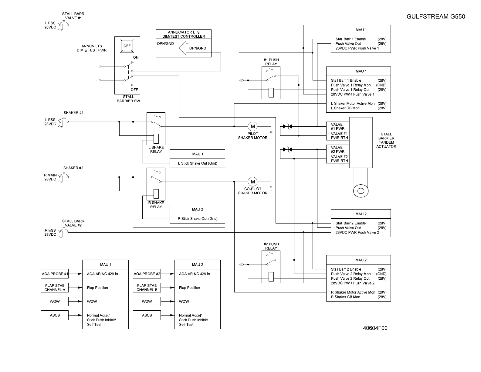
OPERATING MANUAL
Title Page
Prev Page
Next Page
TOC
Stall Warning / Stick
Pusher Block Diagram
Figure 17
2A-27-00
Page 67 / 68
August 14/03
Page 68

Title Page
Prev Page
Next Page
TOC
Page 69
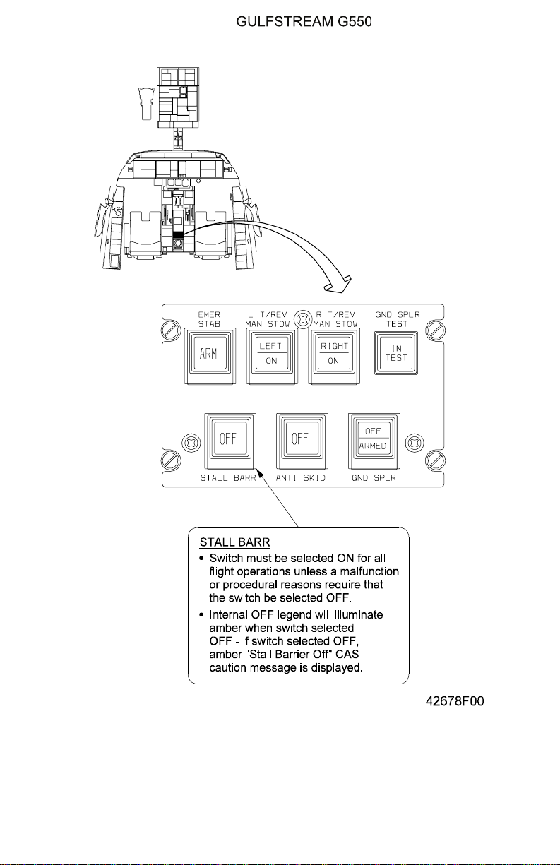
OPERATING MANUAL
Title Page
Prev Page
Next Page
TOC
STALL BARR Switch
Figure 18
PRODUCTION AIRCRAFT SYSTEMS 2A-27-00
Page 69
August 14/03
Page 70

OPERATING MANUAL
Title Page
Prev Page
Next Page
TOC
2A-27-70: Speed Brake and Ground Spoilers
1. General Description:
The speed brake and ground spoilers use six panels on the upper wing surface to
increase drag and reduce lift allowing the flight crew to increase descent rates
and, on landing, to shorten landing roll and increase braking effectiveness by
quickly transferring aircraft weight to the main landing gear wheels. The three
panels on each wing are hydraulically powered and activated by either manual
command through the SPEED BRAKE handle on the pilot side of the cockpit
center console, or electrically actuated as an automatic selectable feature during
landing. The automatic ground spoilers will also deploy during an aborted takeoff
to reduce aircraft stopping distance.
Hydraulic power for speed brake and ground spoiler actuation is provided by both
the left and right hydraulic systems, with the pressure of each system reduced
from three thousand (3,000) psi to fifteen hundred (1,500) psi by a pressure
control module to prevent structural damage to the aircraft from speed brake
deployment at high airspeeds. Two hydraulic actuators on each wing operate the
spoiler panels in response to manual or electrical control inputs. Each actuator
has tandem pistons, one for each hydraulic system, that move a single actuator
shaft. Failure of one hydraulic system will not effect the actuators - the remaining
system pressure reducer will allow a full three thousand (3,000) psi to the
operational piston to power actuator shaft movement, and the condition will by
annunciated by a blue “Single Speed Brake” advisory Crew Alerting System
(CAS) message. Diagrams of the spoiler system is included in Figure 19and
Figure 20.
The two hydraulic actuators are necessary to provide the multi-purpose operation
of the spoiler system. The two outer spoiler panels on each wing operate in three
(3) modes:
• To assist the ailerons in aircraft roll control
• To actuate as speed brakes
• To actuate as ground spoilers
The single inner spoiler panel on each wing operates as:
• A speed brake
• A ground spoiler
The two hydraulic actuators and the three spoiler panels on each wing are
mechanically linked together; however, the linkage is unidirectional, operating
from the inboard ground spoiler actuator outboard to the flight spoiler actuator. All
speed brake or ground spoiler commands, either manual or electric, are directed
to the ground spoiler actuator that mechanically relays the command to the flight
spoiler actuator. The single direction of the mechanical linkage is necessary in
order for the two outboard spoiler panels of each wing to assist the ailerons
without operating the inboard spoiler panel. The aileron control linkage to the
outer panels is a separate command input that is cumulative to the speed brake
deployment command. For more information regarding the roll assist function of
the outer spoiler panels, see section 2A-27-40: Aileron Roll Control.
Both actuator linkages on each wing have dedicated Rotary Variable
Displacement Transducers (RVDTs) that furnish position information to the
Modular Avionics Units (MAUs). The left ground and flight spoiler actuator
linkages are monitored by RVDTs linked to MAU #1, and both right wing spoiler
RVDTs are monitored by MAU #2. The MAUs share position information with the
Page 70
August 14/03
PRODUCTION AIRCRAFT SYSTEMS2A-27-00
Page 71

OPERATING MANUAL
Title Page
Prev Page
Next Page
TOC
Monitor and Warning System (MWS) in order to generate CAS messages in the
event of a malfunction, and to format the graphic display of spoiler position on the
Flight Controls 2/3 synoptic page.
Two additional contact switches, one on each wing, are closed when the spoilers
are flush with the wing surface. The switches, located on the aft wing beam
provide position signals to the MAUs (left spoiler to MAU #1, right spoiler to MAU
#2) confirming that the spoilers are stowed.
If a malfunction of the spoiler system occurs, a single pushbutton, labelled
SPOILER CONTROL, located just forward of the speed brake handle can be used
to deactivate the spoilers. Depressing the pushbutton will illuminate the amber
OFF legend within the button and close two (left and right) spoiler control valves
located in the aft wing to fuselage fairing, bypassing left and right system
hydraulic pressure to the spoiler actuators.
2. Description of Subsystems, Units and Components:
A. Speed Brake:
All six spoiler panels will deploy upward from the wing surface in response
to manual commands from the speed brake handle on the cockpit center
console, shown in Figure 16. An internal light, powered by the right
essential DC bus, will illuminate the speed brake handle as it is moved aft
from the stowed position. The speed brake handle is connected by wire
cables and linkages to the ground spoiler hydraulic actuators that position
the inboard spoiler panels on each wing. The ground spoiler hydraulic
actuators are in turn mechanically linked to the flight spoiler actuators on
each wing that position the middle and outboard spoiler panels. The
amount of spoiler panel deflection is dependent upon the position of the
speed brake handle. The handle may be moved to any range from the
retract position to fully extended position with no detents in the handle
range. At the fully extended position, the two inboard spoilers will deploy to
thirty degrees, plus or minus one degree (30° ±1°) and the two outboard
spoilers on each wing will deploy to thirty degrees, plus or minus four
degrees (30° ±4°). The difference in tolerances from the thirty degree (30°)
full setting is due to the rigging of the linkages between the ground and
flight spoiler actuators.
The position of the SPEED BRAKE handle is monitored by an Input /
Output (I/O) module in MAU #2. When the handle is out of the retract
position, the I/O module communicates with the MWS to generate a blue
“Speed Brake Extended” advisory CAS message. If the power levers are
positioned forward of the idle position with the speed brakes extended, an
amber “Speed Brake Extended” caution CAS message is displayed as a
reminder to the flight crew.
NOTE:
Rapid descents using the speed brake with the power
levers at idle produce high closure rates with the
desired or assigned altitude. If not recognized early,
the recovery response is often to add power to slow
the descent rate without first retracting the speed
brakes.
Additionally, if the flight crew commences a roll command to the ailerons
PRODUCTION AIRCRAFT SYSTEMS 2A-27-00
Page 71
August 14/03
Page 72

OPERATING MANUAL
Title Page
Prev Page
Next Page
TOC
with the yoke or autopilot while the speed brake handle is extended, the
two outboard spoiler panels on each wing will increase displacement over
the speed brake commanded spoiler position to aid in aileron roll control.
The maximum displacement of the outboard spoiler panels is fifty-five
degrees, plus or minus four degrees (55° ±4°) with full speed brake and
aileron commands.
B. Ground Spoilers:
The automatic operation of all six spoiler panels to reduce landing roll
distance or decrease stopping distance in the event of an aborted takeoff is
an electrically controlled function. Ground spoilers use no manual inputs
via control cables or linkages but instead use electro-hydraulic servo
valves to control the flow of hydraulic system pressure within the ground
spoiler hydraulic actuators to extend the spoiler panels. The servo valves
are electrically operated and use left hydraulic system pressure to control
the actuators. If left system pressure is not available, Power Transfer Unit
(PTU) pressure or Auxiliary (AUX) system pressure will operate the servo
valves using left system fluid.
To provide protection against spurious activation of the ground spoilers,
two levels of servo control safeguards are incorporated. The servo valves
are plumbed in series and both must be open to command actuation of
ground spoilers, and each servo valve has an independent electrical power
circuit for operation.
When the servo valves operate the ground spoiler actuators, system
operation is the same as that in speed brake operation: the hydraulic
actuators use both left and right hydraulic system pressure, reduced to
fifteen hundred (1,500) psi. to operate the inboard spoiler panels and the
mechanical linkage to the outboard flight spoiler actuators commands
operation of the two outboard panels on each wing. All six wing panel
spoilers extend to fifty-five degrees plus or minus four degrees (55° ±4°).
For automatic operation, ground spoilers must first be armed using the
GND SPLR pushbutton on the cockpit center console (the SPOILER
CONTROL switch must also be in the ON position). The ground spoiler
pushbutton has two positions, OFF or ARMED, and the corresponding
legend within the pushbutton will illuminate according to the selection
made. See Figure 22. With the pushbutton ARMED, the ground spoilers
will activate whenever all the required elements in the operational logic are
satisfied.
Normal Operational Logic:
Because the simultaneous deployment of all six spoiler panels to fifty-five
degrees (55°) results in such an abrupt change in the wing airfoil, the
logical steps necessary for activation are designed to ensure that
automatic operation occurs only on the ground and with the concurrence of
the flight crew. The following conditions must be met to automatically
deploy ground spoilers during normal landing operations:
(1) The SPOILER CONTROL pushbutton selected ON.
(2) The GND SPLR pushbutton selected to ARM.
(3) Wing flaps selected to greater than twenty-two degrees (22°).
(4) Both power levers retarded to flight idle.
Page 72
August 14/03
PRODUCTION AIRCRAFT SYSTEMS2A-27-00
Page 73

OPERATING MANUAL
Title Page
Prev Page
Next Page
TOC
(5) Both main landing gear weight on wheels (WOW) switches in the
ground position OR both main landing gear wheel speeds (sensed
by the anti-skid sensors) greater than forty-seven knots (>47 kts)
OR one main landing gear WOW switch in the ground position and
the other main landing gear wheel speed greater than forty-seven
knots (>47 kts).
NOTE:
The relationship between the WOW switches and
wheel speed is necessary to accommodate the wide
range of conditions encountered during landing. An
extremely gentle touchdown would spin up the wheels
but not immediately compress the WOW switches. A
very firm landing may compress the WOW switches
but not immediately spin up the wheels. Strong
crosswinds may result in one WOW (upwind) switch
being compressed and the opposite wheel (downwind)
spinning up prior to the WOW switch being
compressed.
CAUTION
A HARD LANDING THAT RESULTS IN A
SIGNIFICANT BOUNCE WILL DEPLOY THE
GROUND SPOILERS IF THE POWER LEVERS ARE
MAINTAINED AT IDLE, RESULTING IN A RAPID
LOSS OF LIFT AND AIRSPEED DURING THE
SUBSEQUENT TOUCHDOWN. ADVANCING THE
POWER LEVERS WILL RETRACT THE GROUND
SPOILERS AND DECREASE THE SINK RATE IF THE
AMOUNT OF RUNWAY REMAINING ALLOWS SAFE
COMPLETION OF THE LANDING.
For automatic ground spoiler deployment in conditions that require landing
with less than full (39°) flaps, the following logic parameters are necessary
for abnormal landing operations:
(6) The SPOILER CONTROL pushbutton selected ON.
(7) The GND SPLR pushbutton selected to ARM.
(8) Wing flaps selected to less than twenty-two degrees (22°).
(9) The GPWS / GND SPLR FLAP ORIDE pushbutton on the center
console forward of the flap handle selected to ON (amber ON
legend in the pushbutton illuminated) - see Figure 21.
(10) Both power levers retarded to idle.
PRODUCTION AIRCRAFT SYSTEMS 2A-27-00
Page 73
August 14/03
Page 74

OPERATING MANUAL
Title Page
Prev Page
Next Page
TOC
(11) Both main landing gear weight on wheels (WOW) switches in the
ground position OR both main landing gear wheel speeds (sensed
by the anti-skid sensors) greater than forty-seven knots (>47 kts)
OR one main landing gear WOW switch in the ground position and
the other main landing gear wheel speed greater than forty-seven
knots (>47 kts).
NOTE:
The GPWS / GND SPLR FLAP ORIDE pushbutton
selection furnishes an alternate relay path bypassing
the flaps greater than twenty-two degrees (>22°)
requirement and also prevents nuisance
annunciations from the GPWS module of the MAUs
due to ground proximity without the normal landing
flap configuration.
To enable automatic deployment of ground spoilers for reducing stopping
distance in event of an aborted takeoff, the following conditions must be
met for normal takeoffs.
(12) The SPOILER CONTROL pushbutton selected ON.
(13) Wing flaps selected to takeoff setting - ten or twenty degrees (10° or
20°).
(14) Power levers advanced greater than idle.
(15) GND SPLR pushbutton selected to ARMED.
(16) WOW switches in the ground mode (compressed).
(17) Power levers subsequently retarded to idle.
Page 74
August 14/03
NOTE:
It is not necessary for wheel speed to increase over
forty-seven knots (47 kts) for the ground spoilers to
deploy during an aborted takeoff.
C. Malfunction Monitoring - Landing and Takeoff:
When the automatic ground spoilers are armed for landing or for aborted
takeoff protection, the system is monitored by the MWS for correct
performance. The MWS verifies all of the control logic parameters, senses
uncommanded pressurization of the ground spoiler control servos, and
circuit integrity to the servos and power lever position switches. If all of the
control logic parameters for the specific aircraft configuration as previously
described have been satisfied, but either or both of the ground spoilers do
not deploy, both red NO GND SPLRS lights located on either side of the
forward windshield center post, will illuminate, a red CAS warning message
of “Ground Spoiler” is displayed accompanied by illumination of the Master
Warning lights on the cockpit glareshield and annunciation of the warning
chime signal over the cockpit speakers. (Ground spoiler operation is
sensed by the stow position contact switches on the inboard spoiler panels
on each wing - the inboard ground spoilers are position monitored since the
mechanical linkage from the inboard actuators operates the actuators for
PRODUCTION AIRCRAFT SYSTEMS2A-27-00
Page 75

OPERATING MANUAL
Title Page
Prev Page
Next Page
TOC
the two outboard flight spoilers.) The malfunction annunciations are
depicted in Figure 22.
NOTE:
Failure of the automatic deployment of ground spoilers
does not preclude operation of the spoiler panels
manually. Extending the SPEED BRAKE handle will
deploy all spoiler panels to thirty degrees (30°) - less
than the full fifty-five degrees (55°) with automatic
operation, but still effective in slowing the aircraft.
At any time the left main landing gear is locked in the down position (inflight
or on the ground) and the GND SPLR pushbutton switch is not in the
ARMED position (amber OFF legend within the switch illuminated), a blue
advisory CAS message reading “Ground Spoiler Unarm” is displayed. The
same message will be displayed if a malfunction in the logic arming
circuitry prevents operation of automatic ground spoilers with the GND
SPLR switch selected toARMED (amber ARMED legend illuminated in the
switch).
D. Malfunction Monitoring Infight:
The uncommanded deployment of a spoiler panel during flight may cause
structural damage or seriously degrade the stability of the aircraft. If the
SPEED BRAKE handle is in the forward stowed position and the GND
SPLR switch is not armed, or if the switch is armed in preparation for
landing but the aircraft is not yet on the runway, and one or both of the
ground spoiler panels is not in the stowed position (sensed by the contact
switches), the red “Ground Spoiler” CAS message will be displayed along
with illumination of the Master Warningglareshield lights and aural warning
tones.
The MWS will also generate a red “Ground Spoiler” warning if conditions
are detected that could cause an uncommanded spoiler activation. Areas
sampled are the same as those described during takeoff and landing with
the addition of fault monitoring of the WOW switches and wheel speed
circuits.
Removing hydraulic power to the spoilers by pulling the SPLR FLT PWR
S/O circuit breaker on the copilot overhead panel will bypass all hydraulic
pressure in the ground and flight spoiler actuators and allow aerodynamic
pressures to stow the extended spoiler panel. See 05-13-60, Ground
Spoiler Failure Inflight..
E. Ground Spoiler Test Switch:
A GND SPLR TEST switch is located on the cockpit center console above
the GND SPLR ARMED / OFF pushbutton as shown in Figure 22.
Depressing and holding in the switch will illuminate the amber IN TEST
legend in the switch and test the following indications:
• Both NO GND SPLRS red lights on the windshield center post will
illuminate
• A red “Ground Spoiler” warning message is displayed on the CAS
window
• The red Master Warning glareshield light and aural warning tones
PRODUCTION AIRCRAFT SYSTEMS 2A-27-00
Page 75
August 14/03
Page 76
OPERATING MANUAL
Title Page
Prev Page
Next Page
TOC
are activated
Prior to the first flight of the day, a complete check of the automatic ground
spoiler system is usually conducted using the test switch and other controls
to verify the operation of the system activation logic. See the Before
Takeoff: 03-04-00 section of this manual for a complete description of the
entire test.
3. Controls and Indications:
(See Figure 21 and Figure 22.)
NOTE:
Since the spoiler panels on the upper wing surfaces
are not visible from the cockpit inflight, the position of
the spoilers is monitored using the Flight Controls 2/3
synoptic page. A full description of the Flight Controls
2/3 synoptic page appears in section 2B-07-00.
A. Circuit Breakers (CBs):
The following CBs protect the spoiler system:
Circuit Breaker Name: CB Panel: Location: Power Source:
SPDBRK ALARM REER A-26 Right Essential DC Bus
SPLR FLT PWR S/O CPOP E-3 Right Essential DC Bus
GND SPLR CPOP E-2 Right Essential DC Bus
LEFT WOW POP C-1 Left Essential DC Bus
RIGHT WOW CPOP C-1 Right Essential DC Bus
WHEEL SPEED POP C-3 Left Essential DC Bus
THROT QUAD CPOP C-2 Right Main DC Bus
B. Crew Alerting System (CAS) Messages:
The following CAS messages indicate the status of the speed brake /
ground spoiler system:
Area Monitored: CAS Message: Message Color:
MAUs #1 and #2, Speed Brake
handle, spoiler panel RVDTs /
stowed contact switches
MAUs #1 and #2, ground spoiler
arming logic circuit, stowed
contact switches
Spoiler Control pushbutton,
spoiler control valves
MAU #2, Speed Brake handle
switch and power lever position
Left main landing gear downlock,
GND SPLR ARMED pushbutton
MAUs #1 and #2, pressure
reducing module
Aircraft Configuration Red
Ground Spoiler Red
Spoilers Hydraulic Off Amber
Speed Brake Extended Amber
Ground Spoiler Unarm Blue
Single Speed Brake Blue
Speed Brake handle switch Speed Brake Extended Blue
PRODUCTION AIRCRAFT SYSTEMS2A-27-00
Page 76
August 14/03
Page 77

4. Limitations:
Title Page
Prev Page
Next Page
TOC
A. Flight Manual Limitations:
(1) Use of Speed Brakes:
Speed brakes are not approved for extension with flaps at 39°
(DOWN) or with landing gear extended in flight.
(2) Automatic Ground Spoilers:
Takeoff is permitted with automatic ground spoilers inoperative
provided the Anti-Skid is operative, 20° flaps are used and the cowl
and wing anti-ice systems are not used. Dispatch with reference to
MMEL.
If a touch-and-go landing is to be performed, the GND SPLR must
be OFF and manual spoiler landing distances must be taken into
account.
OPERATING MANUAL
PRODUCTION AIRCRAFT SYSTEMS 2A-27-00
Page 77
August 14/03
Page 78

OPERATING MANUAL
Title Page
Prev Page
Next Page
TOC
THIS PAGE IS INTENTIONALLY LEFT BLANK.
Page 78
August 14/03
PRODUCTION AIRCRAFT SYSTEMS2A-27-00
Page 79
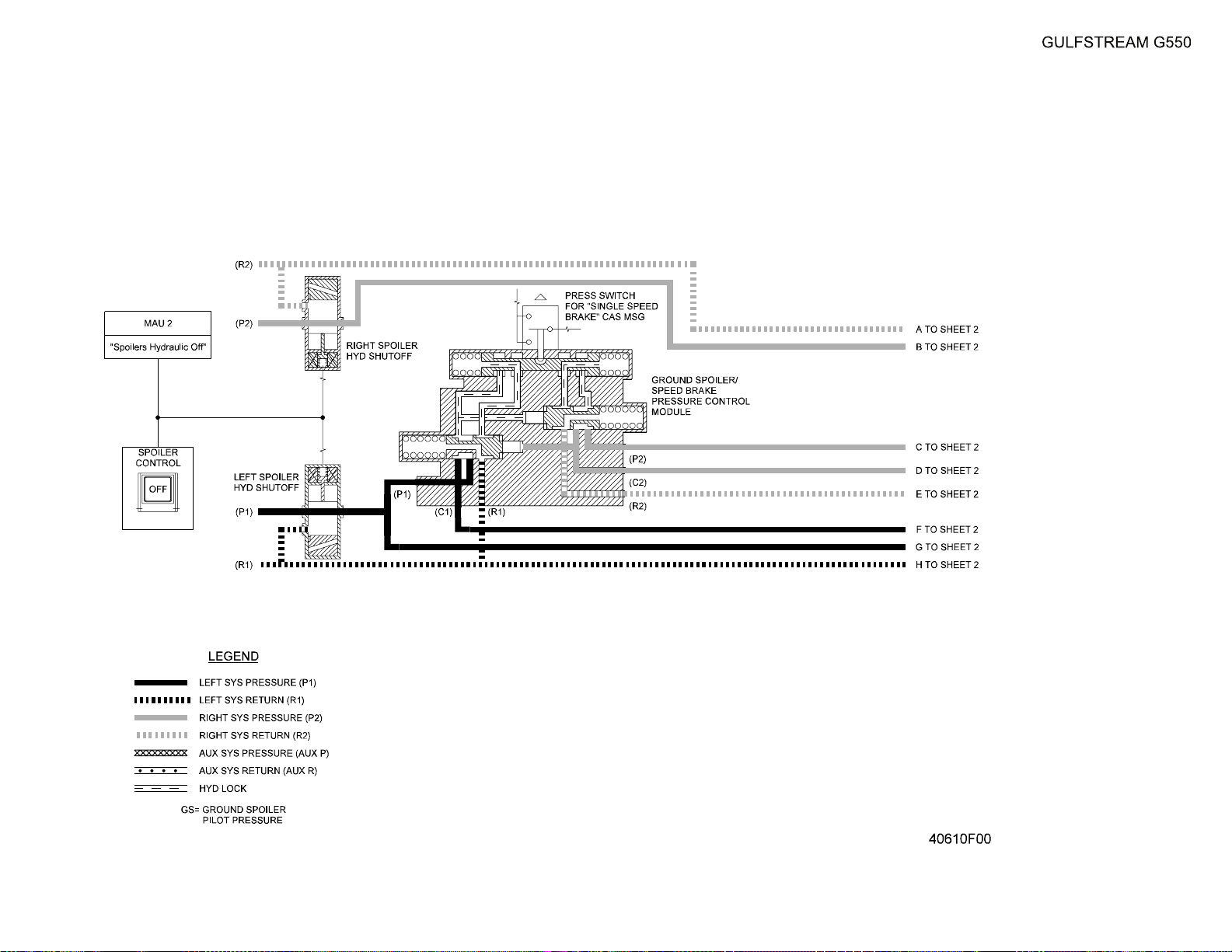
OPERATING MANUAL
Title Page
Prev Page
Next Page
TOC
Spoiler System
Figure 19 (Sheet 1 of 3)
2A-27-00
Page 79 / 80
August 14/03
Page 80

Title Page
Prev Page
Next Page
TOC
Page 81
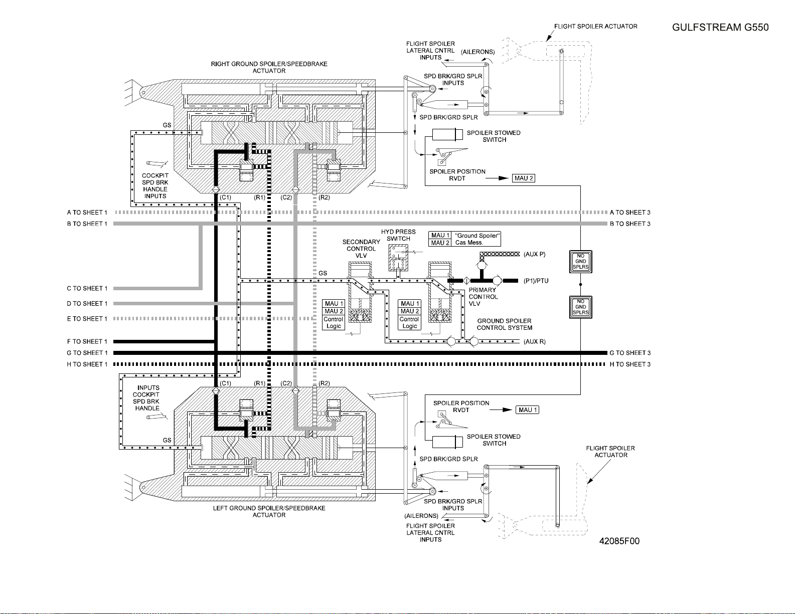
OPERATING MANUAL
Title Page
Prev Page
Next Page
TOC
Spoiler System
Figure 19 (Sheet 2 of 3)
2A-27-00
Page 81 / 82
August 14/03
Page 82

Title Page
Prev Page
Next Page
TOC
Page 83
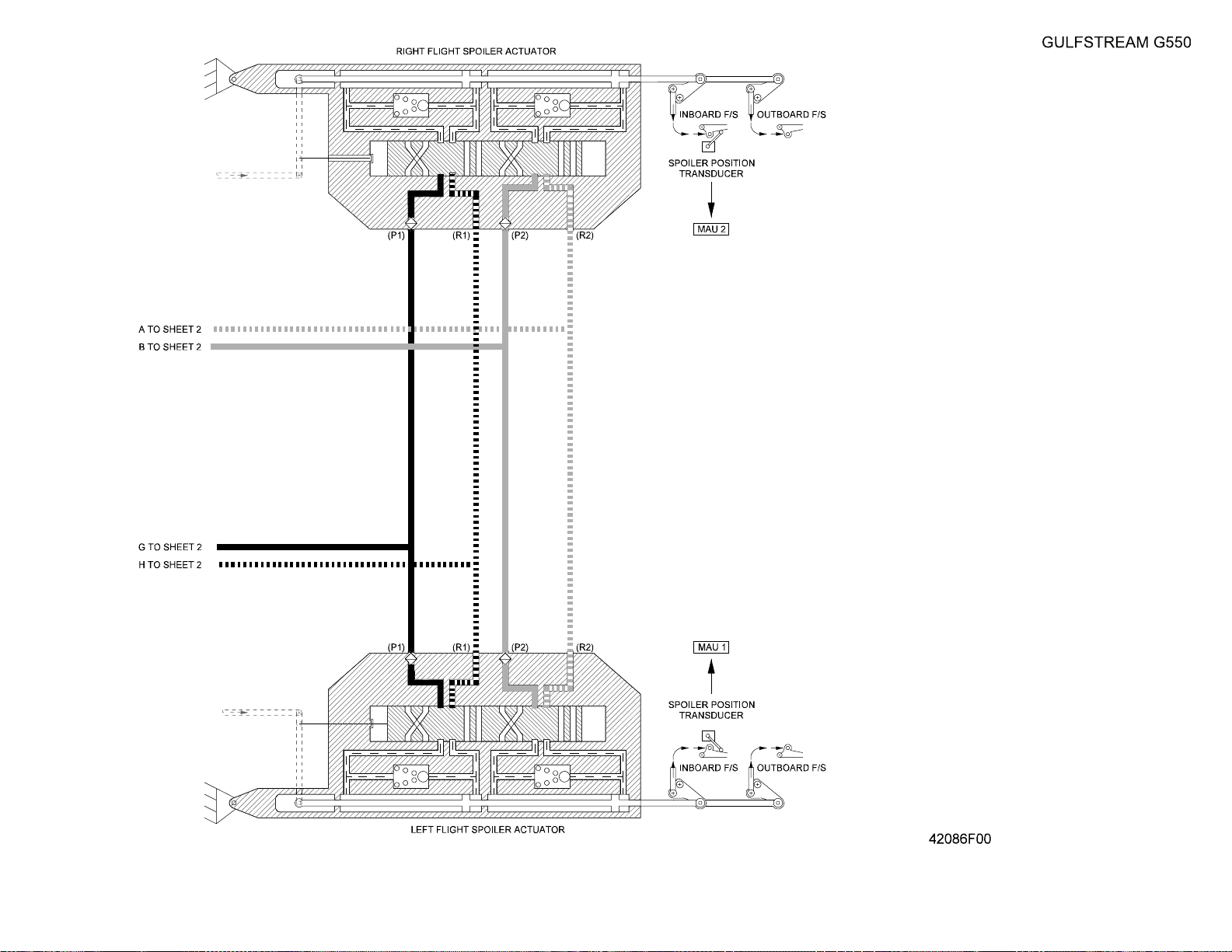
OPERATING MANUAL
Title Page
Prev Page
Next Page
TOC
Spoiler System
Figure 19 (Sheet 3 of 3)
2A-27-00
Page 83 / 84
August 14/03
Page 84

Title Page
Prev Page
Next Page
TOC
Page 85
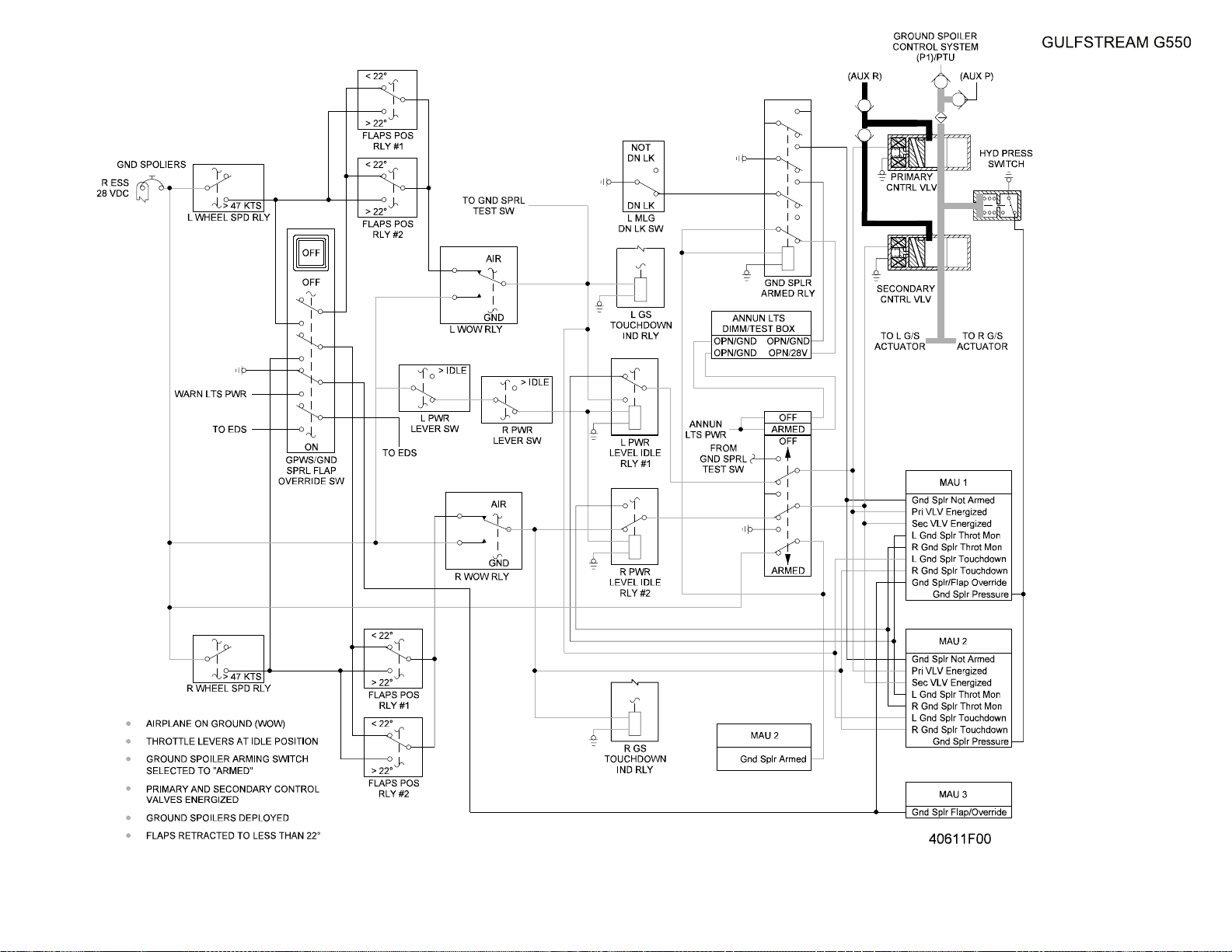
OPERATING MANUAL
Title Page
Prev Page
Next Page
TOC
Ground Spoiler Circuits
Figure 20
2A-27-00
Page 85 / 86
August 14/03
Page 86

Title Page
Prev Page
Next Page
TOC
Page 87
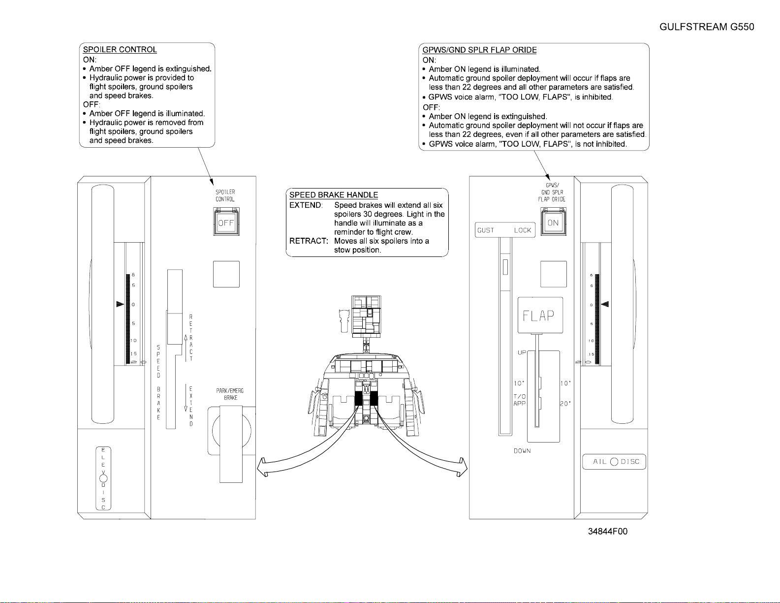
OPERATING MANUAL
Title Page
Prev Page
Next Page
TOC
Spoiler System Controls
Figure 21
2A-27-00
Page 87 / 88
August 14/03
Page 88

Title Page
Prev Page
Next Page
TOC
Page 89
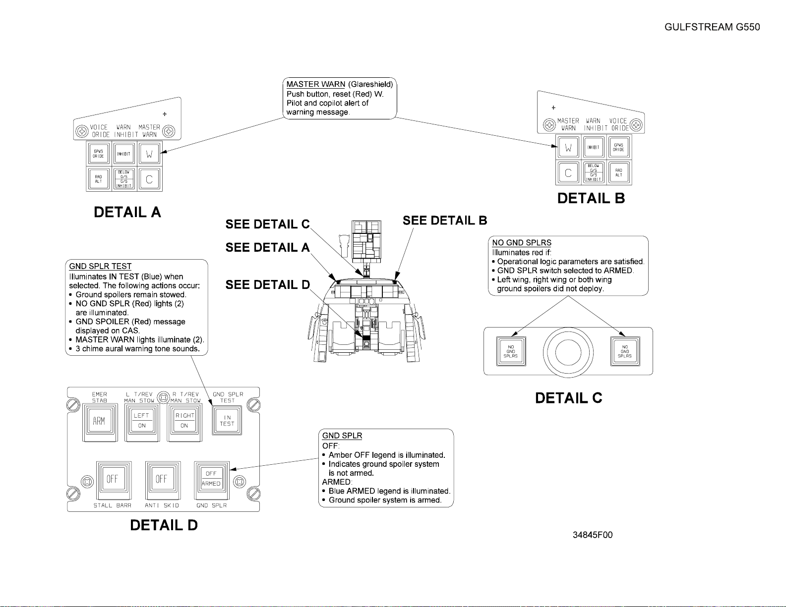
OPERATING MANUAL
Title Page
Prev Page
Next Page
TOC
Spoiler System Indications
Figure 22
2A-27-00
Page 89 / 90
August 14/03
Page 90

Title Page
Prev Page
Next Page
TOC
Page 91

OPERATING MANUAL
Title Page
Prev Page
Next Page
TOC
2A-27-80: Flight Controls Gust Lock
1. General Description:
The flight controls gust lock secures the aircraft moveable surfaces in stabilized
positions to prevent damage to the surfaces and attached control linkages from
high winds or jet blast. A GUST LOCK handle on the copilot side of the cockpit
center console (see Figure 23) is connected through a system of cables, pulleys
and rods to hooks or latches that engage the mechanical linkages of flight controls
to prevent movement. The control surfaces are locked in positions that offer the
best protection to the aircraft. The ailerons and rudder are locked in neutral faired
positions, and the elevators are locked in a slightly trailing edge down position so
that any wind force would tend to maintain weight on the nosewheel to preserve
aircraft stability.
NOTE:
The gust lock is effective in preventing flight control
movement during wind speeds up to sixty knots (60
kts). If weather conditions are forecast to include
stronger winds, consideration should be given to
securing the aircraft within a hangar or other suitable
shelter.
2. Description of Subsystems, Units and Components:
A. GUST LOCK Handle:
The aircraft gust lock is engaged with the T-shaped handle on the cockpit
center console. In order to move the handle from either the engaged or
disengaged position, a spring loaded latch on the back of the handle must
be depressed. The spring latch prevents inadvertent engagement and also
maintains engagement of the gust lock once selected. The handle rotates
aft from the horizontal disengaged position up to a ninety degree (90°)
vertical position when engaged in order provide a strong visual cue that the
aircraft flight controls are locked.
B. Flight Control Latches:
As the GUST LOCK handle is rotated aft and up, the motion is translated
by a cable, rods and pulleys to the locking mechanisms on the flight control
linkages. The lateral motion of the single cable rotates pulleys that in turn
move latching arms into position to engage the command input links of the
flight controls. The latches will not lock in the engaged position until the
flight control is placed in the specified position necessary to minimize the
effect of wind forces on the aircraft. Section 03-06-20: After Landing /
Shutdown contains the following CAUTION notification:
ENSURE HYDRAULIC PRESSURE IS DEPLETED PRIOR TO
ENGAGING THE GUST LOCK. IF IT IS NOT POSSIBLE TO READ
HYDRAULIC PRESSURES BECAUSE THE AIRCRAFT IS WITHOUT
ELECTRICAL POWER, CYCLE THE CONTROLS WITH THE CONTROL
COLUMN, YOKE AND RUDDER PEDALS TO DEPLETE RESIDUAL
HYDRAULIC PRESSURE.
C. Mechanical Power Lever Interlock:
A mechanical interlock within the cockpit center pedestal prevents
advancing the power levers more than six percent (6%) forward of ground
PRODUCTION AIRCRAFT SYSTEMS 2A-27-00
Page 91
August 14/03
Page 92

OPERATING MANUAL
Title Page
Prev Page
Next Page
TOC
idle if the GUST LOCK handle is engaged. The blocking action of the
interlock cannot be overcome with manual force to advance the power
levers.
3. Controls and Indications:
(See Figure 23.)
There are no circuit breakers or CAS messages related to the gust lock.
4. Limitations:
A. Flight Manual Limitations:
There are no limitations for the gust lock system at the time of this writing.
Page 92
August 14/03
PRODUCTION AIRCRAFT SYSTEMS2A-27-00
Page 93
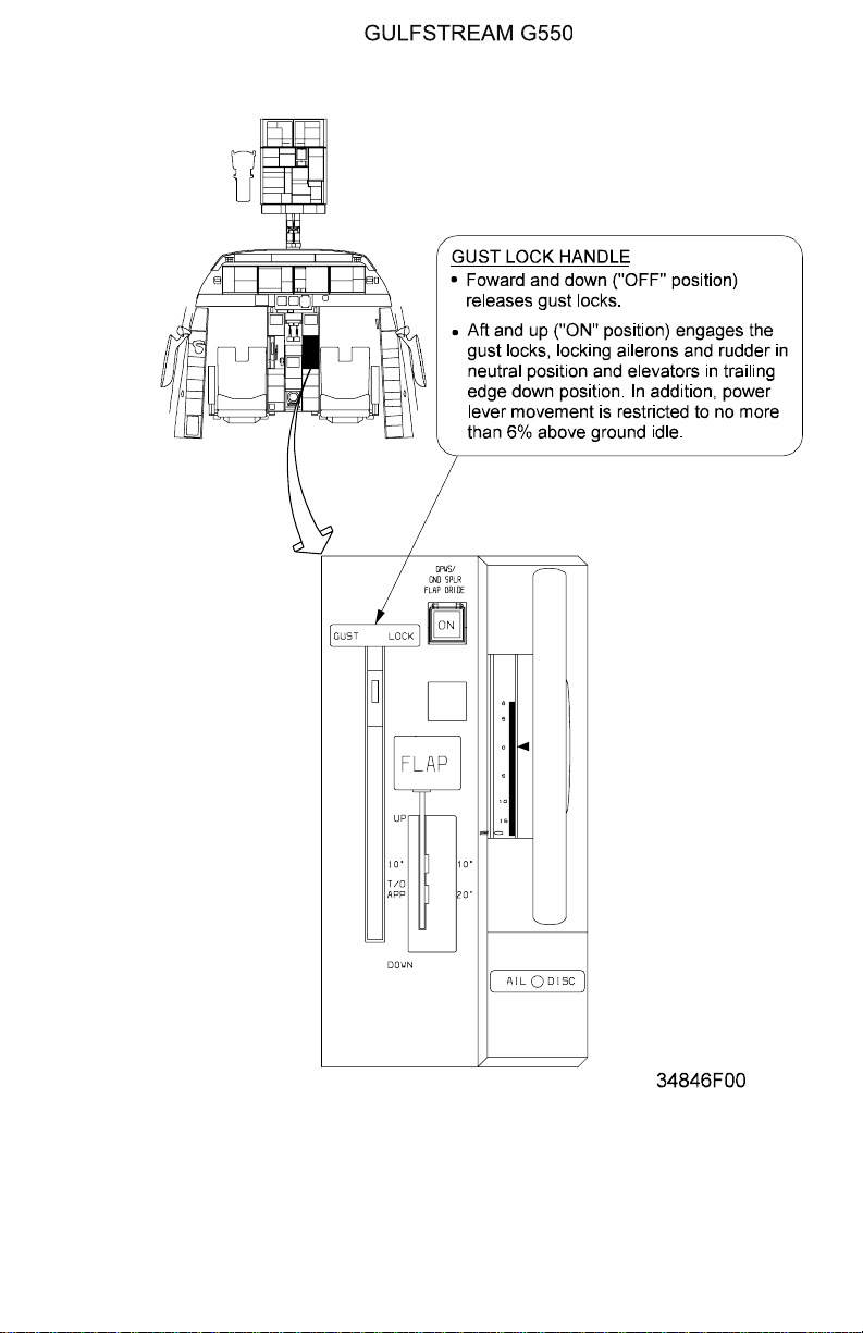
OPERATING MANUAL
Title Page
Prev Page
Next Page
TOC
Gust Lock System Controls
Figure 23
PRODUCTION AIRCRAFT SYSTEMS 2A-27-00
Page 93
August 14/03
Page 94

OPERATING MANUAL
Title Page
Prev Page
Next Page
TOC
THIS PAGE IS INTENTIONALLY LEFT BLANK.
Page 94
August 14/03
PRODUCTION AIRCRAFT SYSTEMS2A-27-00
 Loading...