

Gulf Coast Fans Futura HC-1992-DA Instructions Manual

READ AND SAVE THESE INSTRUCTIONS
Futura HC-1992-DA
Thank you for purchasing a Gulf Coast Fans Inc. product. It will provide
years of cost efficient comfort. With over a decade of experience in ensuring
quality workmanship at an affordable price, we stand behind our product and
we hope you will too.
IMPORTANT PRECAUTIONS
Read these instructions carefully before you start.
1
Turn off the power at the source before installation, servicing, or cleaning.
2
WARNING--TO REDUCE THE RISK OF FIRE OR ELECTRIC SHOCK, DO NOT USE THIS
3
FAN WITH ANY SOLID STATE SPEED CONTROL DEVICE. USE ONLY GULF COAST
CONTROLS.
WARNING--TO REDUCE THE RISK OF PERSONAL INJURY, DO NOT BEND THE
4
BLADE IRONS WHEN INSTALLING ON BLADES, BALANCING THE BLADES, OR
CLEANING THE FAN. DO NOT INSERT FOREIGN OBJECTS IN BETWEEN ROTATING
FAN BLADES.
WARNING--TO REDUCE THE RISK OF FIRE, ELECTRIC SHOCK, OR PERSONAL
5
INJURY, MOUNT FAN TO AN OUTLET BOX MARKED "ACCEPTABLE FOR FAN
SUPPORT" AND USE THE MOUNTING SCREWS PROVIDED WITH THE OUTLET BOX.
If you don't feel comfortable hanging and wiring this fan, we recommend that you hire a
6
qualified electrician to install it.
All wiring and electrical connections must meet the National Electrical Code and any local
7
codes that may apply.
After installation, fan blades must be at least seven (7) feet from the floor.
8
Gulf Coast Fans 2010 - Portions â 1993
Page 1
To begin with, the site of installation must be clear of any obstructions. Walls, cabinet or cupboard doors,
and AC/heating vents (strong air currents will cause fan to wobble ) are common obstructions.
Also, you will need a securely mounted outlet box that is listed for fan support. You may also mount fan
directly to a ceiling joist, but you must use a Ceiling Fan Swag Kit to provide power.
The only tools you will need are : A medium Phillips screwdriver, common sense, and a little caution.
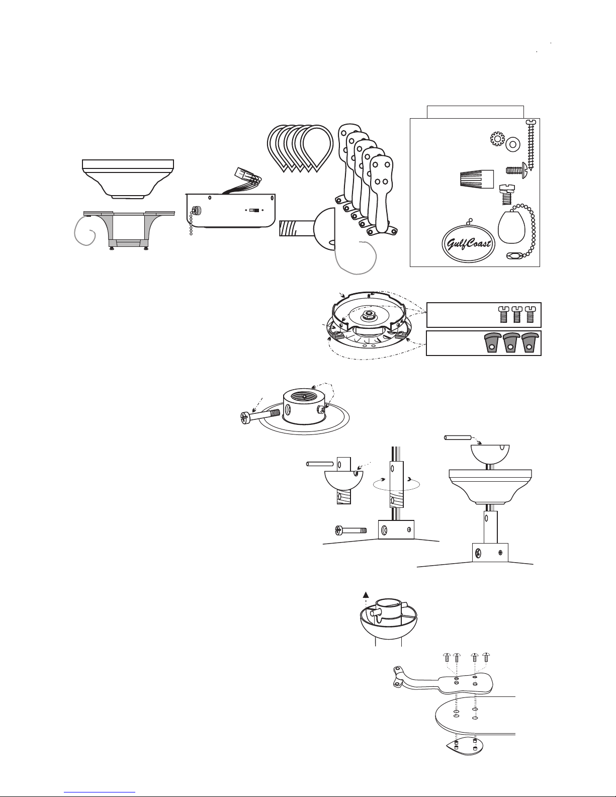
Inventory the parts. Remove all of the parts from the top styrofoam and
I.
remove the styrofoam. Use this top piece to support the fan during
preliminary assembly.
Remove all parts from plastic bags,
A.
including the screw package.
BLADE
BLADE
MEDALLIONS
MEDALLIONS
CANOPYCANOPY
BLADE
BLADE
IRONS
IRONS
2- 3/16"-12x2" Wood Screws
2- 3/8" Star Washers
2- 1/2" Flat Washers
21- 3/16"-32x7/16" Blade Screws
3- Wirenuts
11- Motor Screws
1- Pull Chain Knob
Screw Package
or
SWITCH
SWITCH
CUP
HANGING BRACKET
HANGING BRACKET
w/2 CANOPY SCREWS
w/2 CANOPY SCREWS
CUP
BALL &
BALL &
DOWNROD
DOWNROD
Remove the three screws from the switch cup
B.
plate on motor assembly. See Fig. 1.
Remove and discard the three (to five) black
C.
shipping blocks from the face of the motor.
See Fig 1
Place the motor, switch cup plate
D.
down, in top styrofoam. Remove
the 1/4"-20x1 3/16" threaded pin
from coupler and loosen set
screw(s). See Fig. 2
II. Preliminary Assembly.
Take the ball & downrod and loosen the set
A.1.
screw in the ball. Remove the pin and the ball
from the downrod. (If you have a longer
downrod, use it now.) See Fig. 3
Feed the three wires from the top of the fan through
2.
the downrod and thread the downrod into the coupler.
Align the holes in the downrod with the holes in the
coupler. See Fig. 4
Insert the threaded pin and tighten it and the set screw(s).
3.
Place the canopy around the downrod. Slide the ball onto the downrod and replace pin. See Fig. 5
4.
Raise the ball so that the pin is in the slot and tighten the
5.
set screw. See Fig. 6
Make sure all of the screws are tight. At this time you may
6.
want to shorten the wires from the fan to 6" from the ball.
This helps when you tuck the wires into outlet box.
THREADED
PIN
SWITCH CUP
FIG. 1.
MOTOR
FACE
FIG. 2
FIG. 3
PLATE
PIN
SET
SCREW(S)
SET
SCREW
SWITCH CUP
SCREWS
SHIPPING
BLOCKS
FIG. 4
FIG. 5
FIG. 6
Snap together blade and blade iron. Note the side of the blade you
B.
want to show. Using the 3/16"-32x3/8" blade screws, four of each
per blade, secure blade to blade iron. Repeat this procedure with
the rest of the blades. You will have at least one screw left over, this
is a spare. Be sure all of the screws are tight. Fig. 7
Gulf Coast Fans 2010 - Portions â 1993
Fig. 7
Page 2
 Loading...