

Page 1
GB/US ....GLS5.1 Active lifter
User manual - vers. 2.00
Page 2

GLS5.1 Active lifter
Item nos:
562-xxx
1.00 .........Manufacturer .................................................3
2.00 .........Intended use .................................................3
2.01 .........Where to use GLS5.1 ...........................................3
3.00 .........Denitions ...................................................4
4.00 .........Use of Active lifter .............................................5
4.01 ........Warning ......................................................5
4.02 ........Safety precautions ..............................................6
4.03 .........Checklist before use ............................................6
5.00 .........Operation ....................................................7
5.01 ........Indicator lamps and audio signals ..................................8
5.02 ........Safety functions ................................................9
5.03 ........Important ....................................................10
6.00 ........Charging procedure. . . . . . . . . . . . . . . . . . . . . . . . . . . . . . . . . . . . . . . . . . . 11
7.00 ........Unpacking and preparation of the lifter ..........................11
7.01 .........Assembly instruction ...........................................12
8.00 ........Troubleshooting ..............................................14
9.00 ........Cleaning and disinfection ......................................15
10.00 ........Service and lifespan ..........................................16
11.00 ........Environmental conditions . . . . . . . . . . . . . . . . . . . . . . . . . . . . . . . . . . . . . 17
12.00 .......Technical specications .......................................18
12.01 .......Product conguration table ......................................21
13.00 ........Labelling ....................................................22
14.00 .......EC-Declaration of conformity ...................................24
15.00 ........Environmental policy statement - V. Guldmann A/S ................24
16.00 ........EMC Information .............................................24
17.00 ........Warranty and service conditions ................................27
A. ..........Warranty .....................................................27
B. ..........Service or Repair ..............................................28
2
© Guldmann GB/US-1971/12/2019 • # 558351_2
Page 3

1.00 Manufacturer
V. Guldmann A/S.
Graham Bells Vej 21-23A
DK - 8200 Aarhus N
Tlf. +45 8741 3100
2.00 Intended use
GLS5.1 is a lifting module that covers the need for lifting and moving a person with disabilities.
GLS5.1 is intended for professional use in hospitals, nursing homes, rehabilitation centers and in private homes and buildings, where operators with medical/clinical training are continually available on site or on call.
GLS5.1 is a mobile active lifter which is designed to assist the user from a
sitting to a standing position. It can also be used to assist the user in the
toileting procedure or the beginning of the rehabilitation process. The lifter is
suitable for lifting or moving a person who is capable of actively participating
in the process, the user must also have good communication skills.
When the active lifter is used the assumption is that:
• The user can balance in a sitting position, has strength in the lower and upper
body and can communicate.
• The lifter will be operated by a qualied person.
• The active lifter is moved at a maximum speed corresponding to normal
walking speed.
• The Guldmann active lifter is used with Guldmann lifting slings.
Guldmann cannot be held responsible for any faults or accidents that may
occur due to incorrect positioning of the lifting sling, nor for inadequate attention paid by the helper. We strongly recommend assessment of the user
before every lift.
2.01 Where to use GLS5.1
GLS5.1 is designed to be used in hospitals, nursing homes, institutions and
private homes. It can be used indoors whenever the user needs to be lifted or
moved on a level surface.
• The lifter is designed so its legs can t under beds, around chairs / wheelchairs.
• The lifter can be used in wet areas however, it must not be exposed to splash
water.
• The lifter is designed to be used with multiple users. When moving the lifter to
another user / ward / room, perform normal hygienic disinfection.
© Guldmann GB/US-1971/12/2019 • # 558351_2
3
Page 4
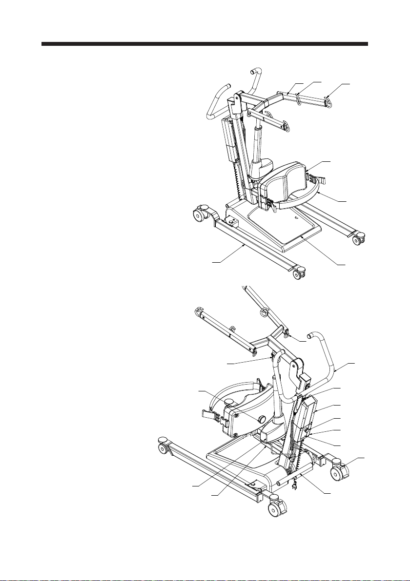
3.00 Denitions
1. Sling attachment hooks
2. Lifting boom
3. Hip support sling attachment
4. Battery
5. Control box
6. Hand control
7. Emergency stop
8. Emergency lowering
electrical
9. Emergency lowering
manual
10. Push handle
11. Calf strap
12. Knee pad
13. Lifting actuator
14. Knee pad height
adjustment knob
15. Knee pad length
adjustment knob
16. Foot plate
17. Chassis leg
18. Brake/release
19. Foot bar
Accessories can be
found in the Guldmann
product catalog
1
2
17
3
1
12
11
16
9
14
13
15
4
10
6
4
7
5
8
18
19
© Guldmann GB/US-1971/12/2019 • # 558351_2
Page 5

4.00 Use of Active lifter
The lifter is designed to lift from a sitting position only. It is NOT designed to
lift from lying position.
Before using the lifter we strongly recommend that a full risk assessment
is carried out by a qualied person to ensure the user capability, the correct slings are used and the environment is suitable. Anyone using the lifter
should be fully trained on its use.
Before every transfer with the active lifter, we strongly recommend you carry
out a quick assessment to assess the user’s capability.
Quick Assessment
With the user in a seated position in chair / wheelchair / edge of bed - ask
the user to push down through his/her knees (feet must be placed at on the
oor) - upon inspection the helper should see the user’s quads tighten. This
indicates strength to assist with the standing procedure, it also conrms com-
munication skills.
4.01 Warning
Read the user manual fully before using the lifter.
• Do not modify this equipment without authorization from the manufacturer
• Do not exceed the max. load.
• Use the lifter to lift a person only.
• Use the lifter on an even and level surface only.
• When adjusting the legs of the lifter make sure that no persons stand close to
the legs due to the risk of being jammed.
• Do not run the lifter into persons or objects.
• Exchange of lifting motor/actuator according to the manufacturer’s instructions. See service chapter
• In case of damage, do not use the lifter until authorized by qualied service
sta or the Guldmann service team.
• Do not use the lifter in areas where it can be splashed with water.
• The lifter needs special precautions regarding EMC and needs to be installed
and put into service according to the EMC information provided in Chapter 17
EMC Information.
• Portable and mobile RF communications equipment can aect the lifter.
• The use of ACCESSORIES, transducers and cables other than those
specied, with the exception of transducers and cables sold by Guldmann A/S
of the lifter as replacement parts for internal components, may result
in increased EMISSIONS or decreased IMMUNITY of the lifter.
• The lifter should not be used adjacent to or stacked with other equipment
and that if adjacent or stacked use is necessary, the lifter should be observed
to verify normal operation in the conguration in which it will be used.
• The lifter is not intended to be driving over steps and thresholds.
© Guldmann GB/US-1971/12/2019 • # 558351_2
5
Page 6
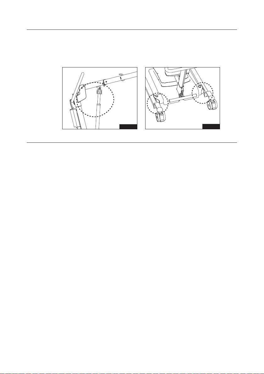
4.02 Safety precautions
• Risk of entrapment between the top of the lifting actuator and lifting arm.
• Risk of entrapment between the legs and the chassis when adjusting the
legs.
4.03 Checklist before use
• The lifter must be o charge.
• Check the lifter is lifting and lowering and the legs are opening and closing, if
you hear the audio warning (a beeping sound) DO NOT USE THE LIFTER –
it needs to be charged.
• Check that the green light located on the hand control is illuminated when the
lifter is activated.
• Check that the emergency stop and lowering is working (See section 5.02
safety features).
• Make sure the lifter is running freely.
• Check the slings for damage or fraying.
Once you have tted the sling (See section about placing the sling in the
manual for Standing sling and Hip Support sling) you are ready to lift.
With the user in a seated position
• If the user is in a wheelchair or commode chair the brakes must be applied.
• Position the lifting boom at lowest position and introduce the lifter square onto
the user. The helper should be positioned at the side of the lifter (to ensure
the lifter does not run over the user’s feet).
• Open the lifter’s chassis leg width adjustment to allow access around the
chair.
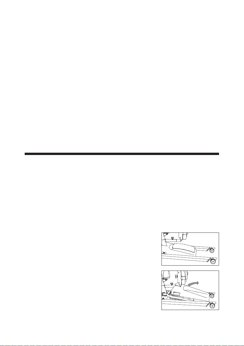
• Position the user’s feet at onto the foot plate and adjust the knee pad - the
top of the knee pad should be level with the top of the shin, two ngers below
the knee joint.
• OPTIONAL – if the user has a tendency to have involuntary movements you
can use the calf strap to ensure the users’ feet do not come o the foot plate.
If the calf strap is not in use, fasten the strap to the back of the knee pad
(avoiding loose straps).
Fig. 1
Fig. 2
6
© Guldmann GB/US-1971/12/2019 • # 558351_2
Page 7
• Raise the lifting boom to gain tension on the sling - ENSURE THE SLING IS
STILL SECURE AND ATTACHED BEFORE CONTINUING WITH THE LIFT.
Communication should be maintained throughout the lifting procedure.
Alternatively you have the option to attach the sling onto the lower hooks; this will
facilitate an alternative lifting position and is more suitable for the shorter user.
To lower the user back into a seated position push the lifter up to the chair
/ commode chair / toilet and position the user so the calf is parallel to the
chair / commode chair / toilet. Begin to lower and ask the user to push his/her
pelvis / hip backwards to ensure the correct seated position.
• Release the sling straps and move the lifter away from the user.
• The sling is ready for removal - see sling user guide.
Working with the Active lifter
• Always maintain a good working posture when applying the sling or working
with the lifter. When moving a person use the push handle and walk with the
lifter keeping the load as close as possible to your body. NEVER pull or twist
at arm’s length, this can cause injury to the helper.
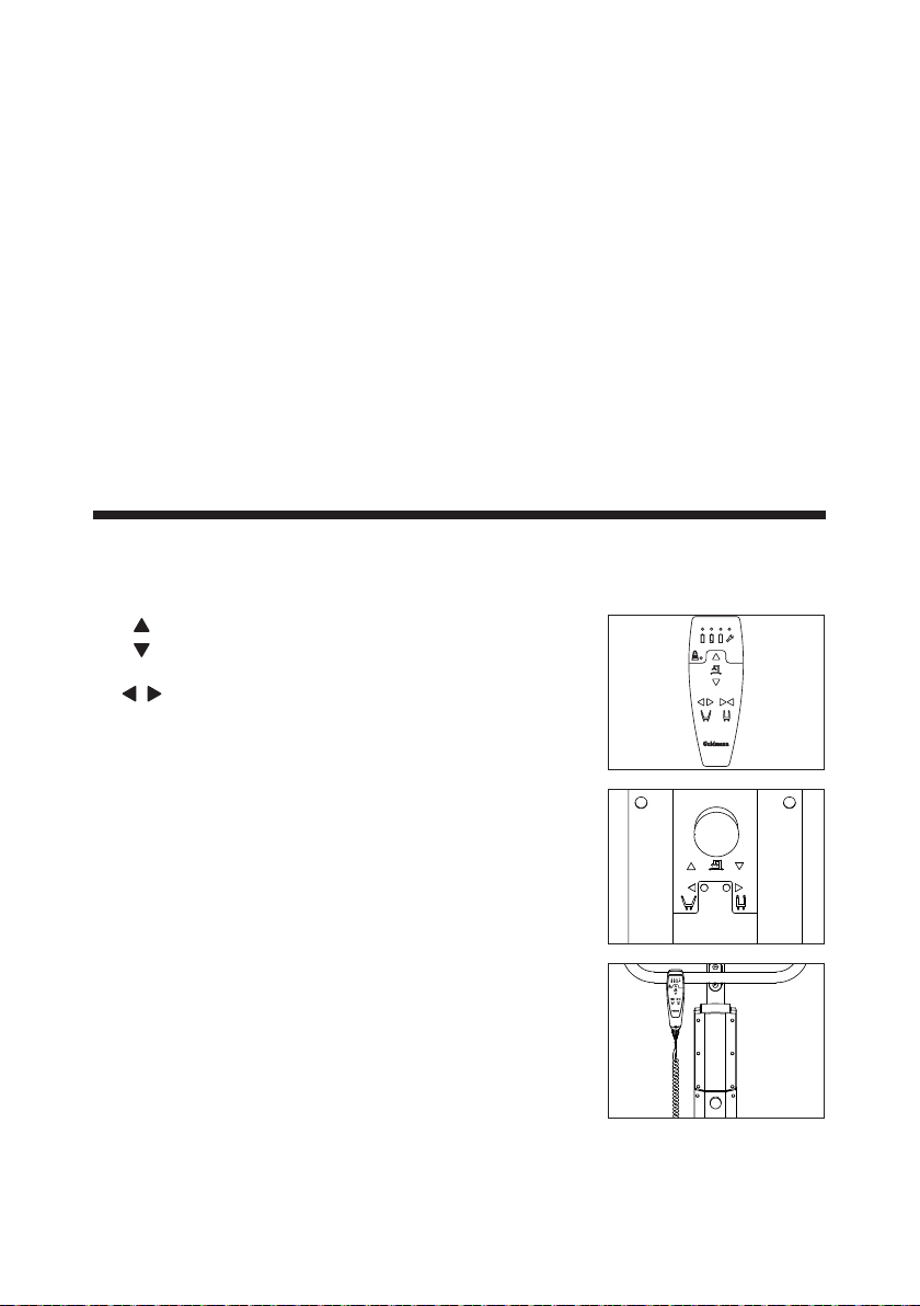
5.00 Operation
To lift/lower and adjustment of chassis leg in/out
• To lift the patient press UP arrow and to lower
the patient press DOWN arrow on the hand
control or the control box.
• On GLS5.1 active lifter the leg spread width
adjustment of the chassis is operated via the
sideways arrows on the hand control or the
control panel on the control box.
• Use max. width setting when lifting to/from
wide chairs, or as necessary when lifting to/
from bed, toilet and chair.
• When not in use, the hand control is designed
to be placed on the push handle.
• When maneuvering the lifter the chassis legs
must be in the closed narrow position.
• The lifter will go into standby after 2 min.
without use.
© Guldmann GB/US-1971/12/2019 • # 558351_2
7
Page 8
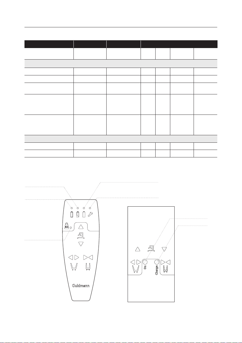
5.01 Indicator lamps and audio signals
Status Indicator lamps Audio signals Possible GLS5.1 signals
Up Down Leg spread Emergency
Hand control
All OK Green x x x x
Low battery Yellow x x x x
Critically low Battery Yellow Beeps at button
Lifter service Yellow
Over load Yellow
Control box
Charger Green + Yellow
Charged Green
Is lit during use
and 2 minutes
after
Flashes 3 times
+ lights up for 10
seconds.
activation
x x x x
x x x x
x x
down
Yellow light
(battery 25-50 %)
Yellow light
(battery 0-25 %)
Yellow light
(overload)
Green light (battery 50-100 %)
Yellow service light
Control boxHand control
8
Green light
Yellow light
© Guldmann GB/US-1971/12/2019 • # 558351_2
Page 9
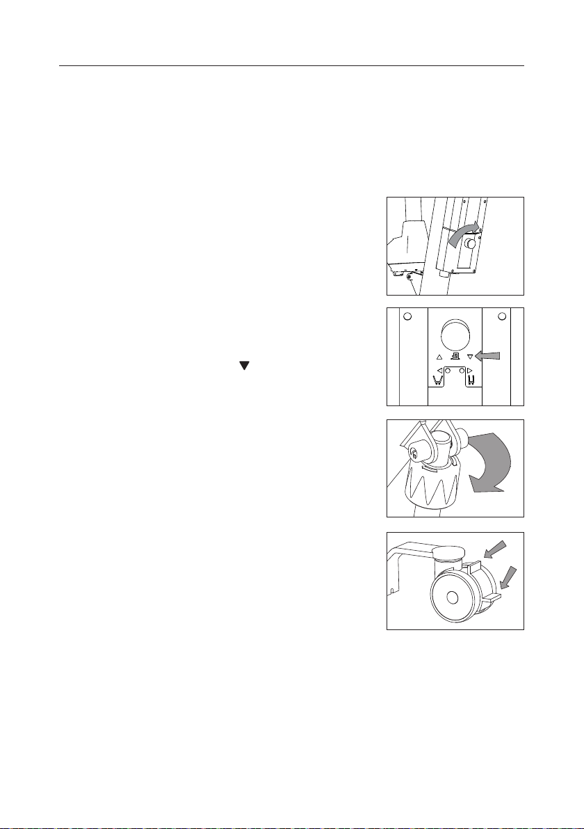
5.02 Safety functions
Only use the emergency stop button and emergency lowering functions in
emergencies. If it has been necessary to apply the emergency/safety functions due to an error on the lifter, the supplier must be contacted prior to
using the lifter again.
In order to disconnect the lifter from mains supply, pull the mains plug out of
the power out-let.
Activating the emergency stop function
Should the lifter not respond to the functions selected on the hand control when it is
in motion, press emergency stop. When the
emergency stop function is applied, the lifter
ceases to function. Switch the lifter on again
by turning the emergency stop button in the
direction of the arrow until it jumps out.
Activating the emergency lowering function
If the lifter fails to lower, activate the following:
1. Press the arrow key
on the control box.
This functions as an emergency lowering
in case the hand control does not work.
If the lifting boom does not lower
2. Turn the red knob in the direction of the arrow
(Used if the actuator has a manual emergency
lowering device)
Use of brakes
The rear castors are tted with brakes. Apply
the brake by stepping on the lower kick pedel.
To release the brake, kick the top part of the
kick pedal.
Only apply the brakes if the user is pushing
the lifter away with his/her feet on the foot plate
while the user is seated in the chair, wheelchair, toilet or commode.
© Guldmann GB/US-1971/12/2019 • # 558351_2
9
Page 10
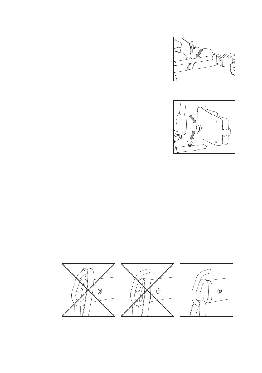
Use of foot bar
The foot bar is there to assist the helper to
initiate movement, and to facilitate the clearing of door thresholds, without a patient in the
lifter or to assist loading into vehicles. This is
achieved by placing one foot onto the foot bar
and gently pulling back on the push handle.
Adjustment of knee pad
The knee pad can be adjusted in vertical and
horizontal direction to t the dierent users.
Vertical: Adjust by unscrew the yellow knob,
lift or lower the knee pad in right position and
then tighten the knob.
Horizontal: Loosen the yellow knob, then
slide the knee pad in or out until it ts the user.
Then tighten the knob clockwise to lock the
knee pad safely.
5.03 Important
• Read the user manual and familiarize yourself with the controls and safety
features on the lifter.
• Always plan your lift before commencing.
• Only use slings that are designed to be used with the active lifter.
• Never use slings that are damaged, frayed or have unreadable labels.
• Check to make sure the user does not exceed the safe working load of the
lifter.
• For safety reasons we DO NOT recommend transporting users through
standard door frames.
• Caution must be exercised when mounting the sling lifting straps onto the
lifting hooks of the boom.
10
© Guldmann GB/US-1971/12/2019 • # 558351_2
Page 11
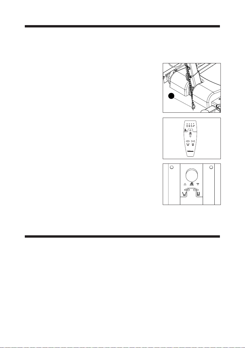
6.00 Charging procedure
Recharge lifter every night or when it is not in use. This maintains the batteries and ensures a long life span. Avoid fully discharging the battery.
Recharging
• Recharge by plugging the power cord
(pos. 15) into a wall socket. While charging,
the green and yellow LEDs on the control box
are always lit.
• The green LED on the control box is lit during
charging when the power cord is plugged in.
• The power supply is automatically disconnected when the lifter is fully charged. The yellow
“Charge” LED turns o on the control box.
• To be recharged when a yellow LED positioned
above a battery symbol on the hand control is
lit.
• When the yellow LED of the empty battery indicator is lit on the hand control and the alarm
sounds, there is limited use of the mobile lifter.
• The lifter cannot be used while charging.
• Do not recharge in wet areas/bathrooms.
• Maximum recharging time is approx. 4 hours.
15
Note!
Ensure the wall socket is turned o when connecting the power cord to the
control box to charge the battery.
7.00 Unpacking and preparation of the lifter
Visual check of lifter
If the packaging is damaged on receipt, each part of the lifter must be careful-
ly examined for visible defects or deciencies. In case of suspected damage,
do not use the lifter until authorized by qualied service sta or the Guldmann
Service Team.
© Guldmann GB/US-1971/12/2019 • # 558351_2
11
Page 12
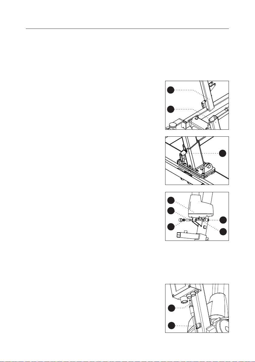
7.01 Assembly instruction
Guldmann recommends that the person making the assembly of the Active
Lifters have a basic mechanical understanding.
Unpack the lifter on to a level surface and gently remove cable ties and
protective-foam.
Assembling mast/chassis
Insert the mast (pos. 1) and lifting arm into
the chassis (pos. 2), make sure that the mast
hits the chassis in the bottom of the chassis
tube.
Tighten the assembly screw (pos. 3) by
turning the handle Clockwise, push to get a
rm grip, pull to adjust the handle positio
1
2
3
Fitting actuator
Fasten the lifting actuator base (pos. 4) on
to the mast by inserting the Pipe (pos. 5),
secure bolt (pos. 6) and locknut (pos. 7) by
tightening them.
Complete by adding protective plastic caps
(pos. 8) to not and bolt.
Actuator motor housing must face right seen
from the front.
Fasten the actuator on to the lifting arm in the
same way.
Mounting of connectors for motors
Insert connector from the lifting actuator to
port 1 (pos. 9) on the control box.
Insert the cable from the lifting actuator into
the cable clips. (pos. 10)
12
4
5
8
7
6
9
10
© Guldmann GB/US-1971/12/2019 • # 558351_2
Page 13
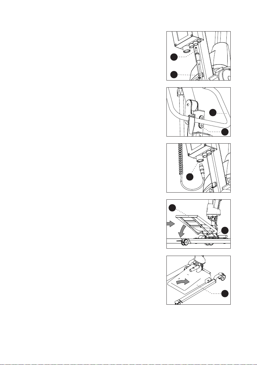
Insert connector for width adjustment motor to
port 2 (pos. 11) on the control box. Insert the
cable from the width adjustment motor into
the 2 cable clips (Pos. 10)
Fasten push handle (pos. 12) to mast by
tightening the Two screws (pos. 13).
Mounting of the hand control
Connect the hand control to the DIN port
on the control box (pos. 14).
11
10
12
13
14
Attach on the footrest (pos. 16) to the chassis
(pos. 2) by lifting the end and inserting the
16
footrest, then turn down to lock it in to place.
2
Put on the footrest cover (pos. 17).
17
© Guldmann GB/US-1971/12/2019 • # 558351_2
13
Page 14
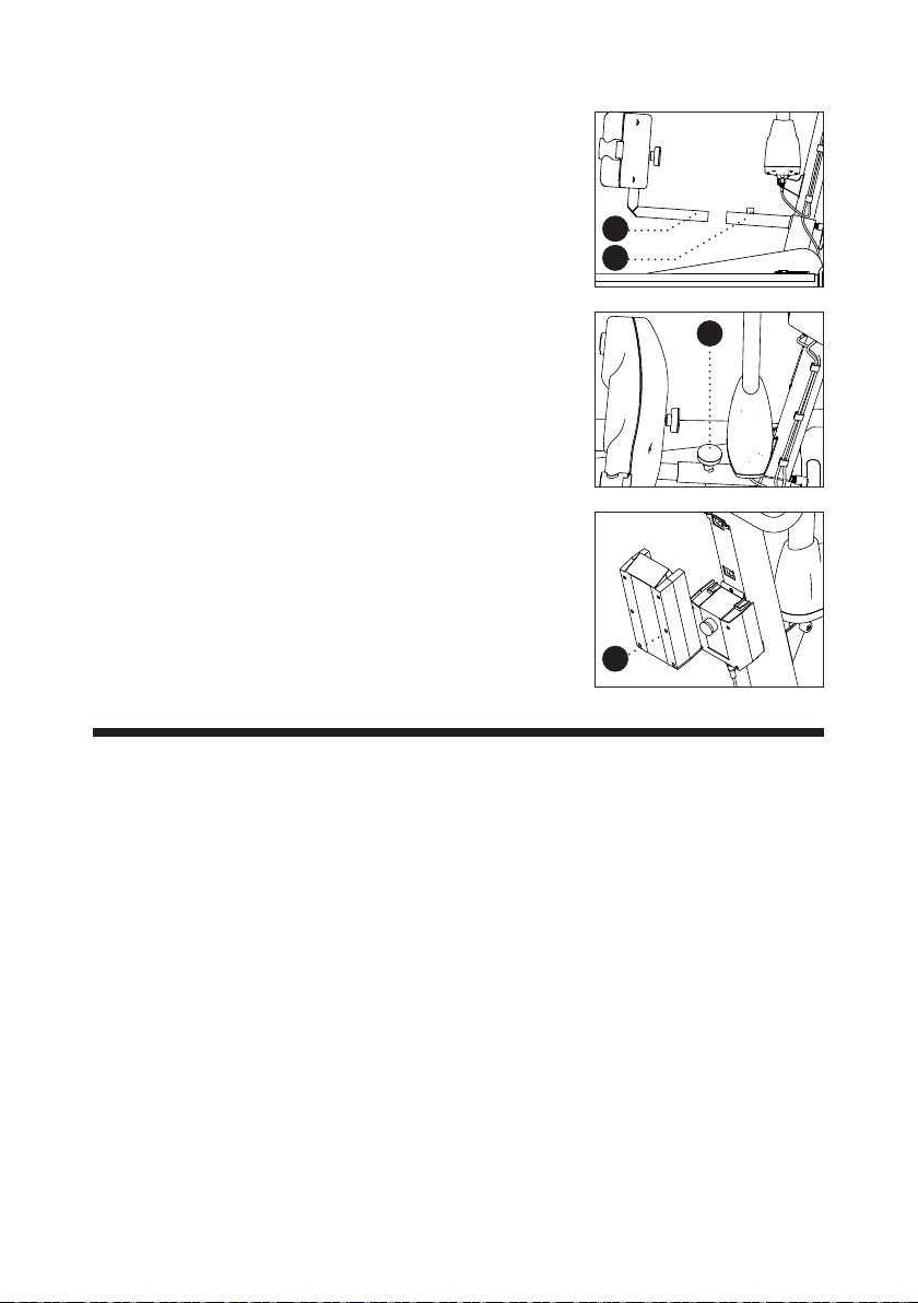
Insert the knee pad (pos. 18) in to the square
tube on the Chassis (pos. 2).
18
2
Secure the knee pad with the adjustment
knob (pos. 19).
Before use, the battery needs (pos. 20) to be
fully charged. See charging procedure.
Remove battery packaging and mount the
battery on top of the control box. The battery is mounted and secured correctly after
hearing a click.
8.00 Troubleshooting
Error:
Lifter does not react to input from the buttons on the hand control.
1. Does the green or yellow LED on the hand control light up when the
control buttons are activated?
Yes see point 6.
No no light visible – see point 2.
No only yellow light visible – see point 3.
No yellow service light visible or audible “Beep”– see “indicator and audio
signals matrix” point 13.01.
19
20
2. Is the battery mounted on the lifter?
Yes see point 4.
No install a fully charged battery.
3. Is a battery with sucient charge installed in the lifter?
No install a fully charged battery or charge the battery.
14
© Guldmann GB/US-1971/12/2019 • # 558351_2
Page 15
4. Is the emergency stop activated?
Yes turn emergency stop in the direction of the arrow to allow it to release
and press any button on the hand control.
No see point 5
5. Is the connector for the hand control tted in the lifter, and is the lifter
reacting to the buttons located on the control box?
Yes replace hand control
No t connector
6. Are the connectors for the lifting motor and/or leg adjustment motor
tted?
Yes see point 5
No t connector
Contact the Guldmann Service Team if the fault cannot be found and
corrected.
9.00 Cleaning and disinfection
We recommend that the products and the parts patients and caregivers can
come in contact with, are cleaned with a damp cloth using warm water and a
mild soap solution.
When disinfection is needed, use disinfectant wipes with up to a 85% solution of
isopropyl, or a damp cloth using warm water and a disinfectant cleaner, e.g. an
chlorine dissolving up to 1500 ppm.
If other chemicals and/or liquids with higher resolution should be used to clean
or disinfect these products, please contact Guldmann providing the item´s safety
sheet chemical composition for consideration.
Caution: Take great care to ensure that no
liquids get inside the lift. The lift is not waterproof. Failure to protect the lift from liquids
may result in damage to the lift and/or may
cause personal injury.
For easier cleaning of the foot plate it can be
lifted o.
The grey inserted plate can be removed separately for cleaning. Footplate and grey insert
plate can be cleaned using hot water and disinfecting soap.
© Guldmann GB/US-1971/12/2019 • # 558351_2
15
Page 16
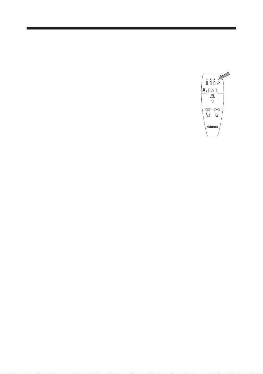
10.00 Service and lifespan
According to the international standard EN/ISO 10535 “Lifter for the transfer
of disabled persons - Requirements and test methods” a safety inspection of
the lifter must be performed at least once a year.
The lifter has an expected lifespan of 10
years. The lifespan is estimated on the basis
of correct use, cleaning and maintenance,
plus annual service and maintenance car-
ried out by qualied service engineers of the
Guldmann Service Team. At the end of the
expected life span, the lifter must then be
assessed by qualied service sta as to the
lifters future use. The lifespan of the lifting
actuator is determined by how regular the
lifter is used.
No part of the equipment shall be serviced when in use with a patient.
The lifter is controlled by a microprocessor PC board which can be damaged
if it is being touched without the necessary precautions. Therefore the elec-
tronics must only be serviced by qualied Guldmann Team.
Spare parts lists and drawings are available from manufacturer or supplier.
16
© Guldmann GB/US-1971/12/2019 • # 558351_2
Page 17
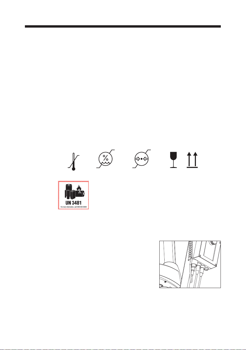
11.00 Environmental conditions
Operation
The products operational environment:
– Operation temperatures between 10 and +35°C / 50 and 95°F
– A relative air humidity of between 30 and 70 %
– An air pressure of between 700 and 1060 hPa
Information is illustrated by symbols on packaging including:
– Fragile
– This side up
– UN 3481 Li-Ion battery
Beside temperature, the same environmental conditions apply for transportation and storage.
– Transport and storage temperatures between -10 and +40°C / 14 and
104°F
Symbols on the packaging:
70%
70 kPa
-10ºC
14ºF
40ºC
104ºF
30%
Transport and storage
The lifter can be dismantled for transport and storage.
1. Detach the power cable that connect lifter´s
bottom frame to port 2 on control box.
106 kPa
© Guldmann GB/US-1971/12/2019 • # 558351_2
17
Page 18
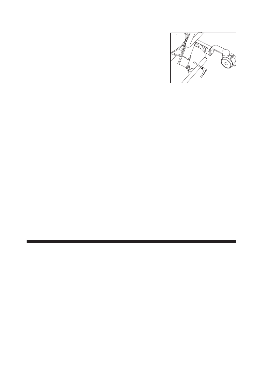
2. Loosen the knob and lift the mast from the
base.
How to pack the lifter for transport
Guldmann recommends that the dismantled lifter is always transported in its
original packaging.
Storage of active lifter
The active lifter should be stored in a dry room. The active lifter must neve
be stored in bathrooms and similar areas.
Always activate emergency stop when the active lifter is put on storage.
If the lifter is not used for a long period, it can be necassay to periodicly
check or charge the battery.
How to prevent/avoid corrosion
The active lifter should not be stored/remain in damp surroundings for long
periods of time. Water vapor might liquefy into water on the active lifter, thus
causing corrosion/rust in bearings as well as in the tubular steel frame.
The active lifter should not be exposed to sudden cold or warmth. This means
that one should not take a cold active lifter into a hot bathroom. In swimming
baths and bathrooms where strong gases may be present, the active lifter is
particularly exposed to corrosion and should always be removed from such
places after use.
12.00 Technical specications
Functions
Lifting capacity, max ....................................155/205 kg
Operation
Lift .....................................................Electric
Width adjustment .........................................Electric
Pushbuttons - max. ......................................... 3.3 N
Knee pad ...............................................Manual
Lifting boom .............................................Manual
18
© Guldmann GB/US-1971/12/2019 • # 558351_2
Page 19

Weight
Totally ................................................... 54 kg
Chassis without foot plate & knee pad .......................... 23 kg
Mast and lifting boom incl. control box & battery ..................20 kg
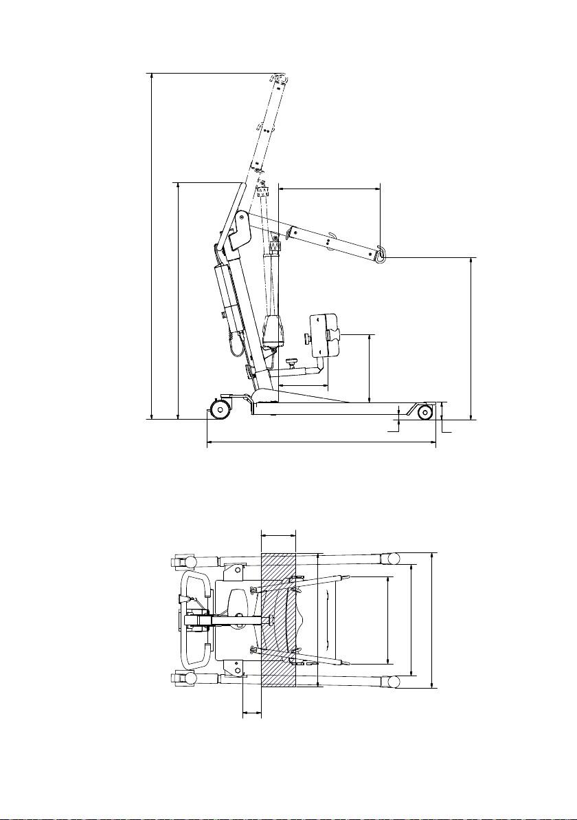
Measurements
A ...................................................... 25 mm
B ......................................................90 mm
C ....................................................1770 mm
D ....................................................1237 mm
E .....................................................575 mm
F .................................................... 1210 mm
G ..................................................... 460 mm
H min/max ..........................................850/1740 mm
I min/max ...........................................350/450 mm
J min/max ..........................................560/1190 mm
K min/max: ..........................................670/1310 mm
L min/max ...........................................230/320 mm
Turning radius
Turning radius .........................................1360 mm
Safety Features
Emergency stop .............................................Yes
Emergency lowering ..............Yes, electronic. Mechanical on request
Protection against trapping .....................................Ye s
Electrical parts
On/o .............................................Automatically
Integrated Power supply for charging
Input ............................. 100-240Vac, 50-60 Hz, 39-53VA
Battery, replaceable Li-Ion ............................25,9 V / 2,25 Ah
Charging time. . . . . . . . . . . . . . . . . . . . . . . . . . . . . . . . . . . . . . . . Max. 4 hours
Consumption/power of actuator ...........................24V, max 8A
Duty Cycle .......................Max 10%, max. 2 min on, 18 min o.
Battery protection ..............Switches o automatically at low voltage.
........................... Diode light up to indicate critical voltage.
Class of tightness
Mobile hoist ............................................... IP 30
Hand control. . . . . . . . . . . . . . . . . . . . . . . . . . . . . . . . . . . . . . . . . . . . . . . IPX 4
Integrated Power supply ..................................... IPX 4
Battery ................................................... IPX 5
Actuator . . . . . . . . . . . . . . . . . . . . . . . . . . . . . . . . . . . . . . . . . . . . . . . . . . IPX 4
Labelling
The product is manufactured in compliance with the Council Directive
93/42/EEC of June 14th 1993, including amendments, as medical device
class 1.
Classied
© Guldmann GB/US-1971/12/2019 • # 558351_2
Acc. to ISO 9999 ........................................12 36 03
19
Page 20
180
115
180
700
C
D
H
115
180
L
F
700
I
A
G
B
J
K
20
© Guldmann GB/US-1971/12/2019 • # 558351_2
Page 21
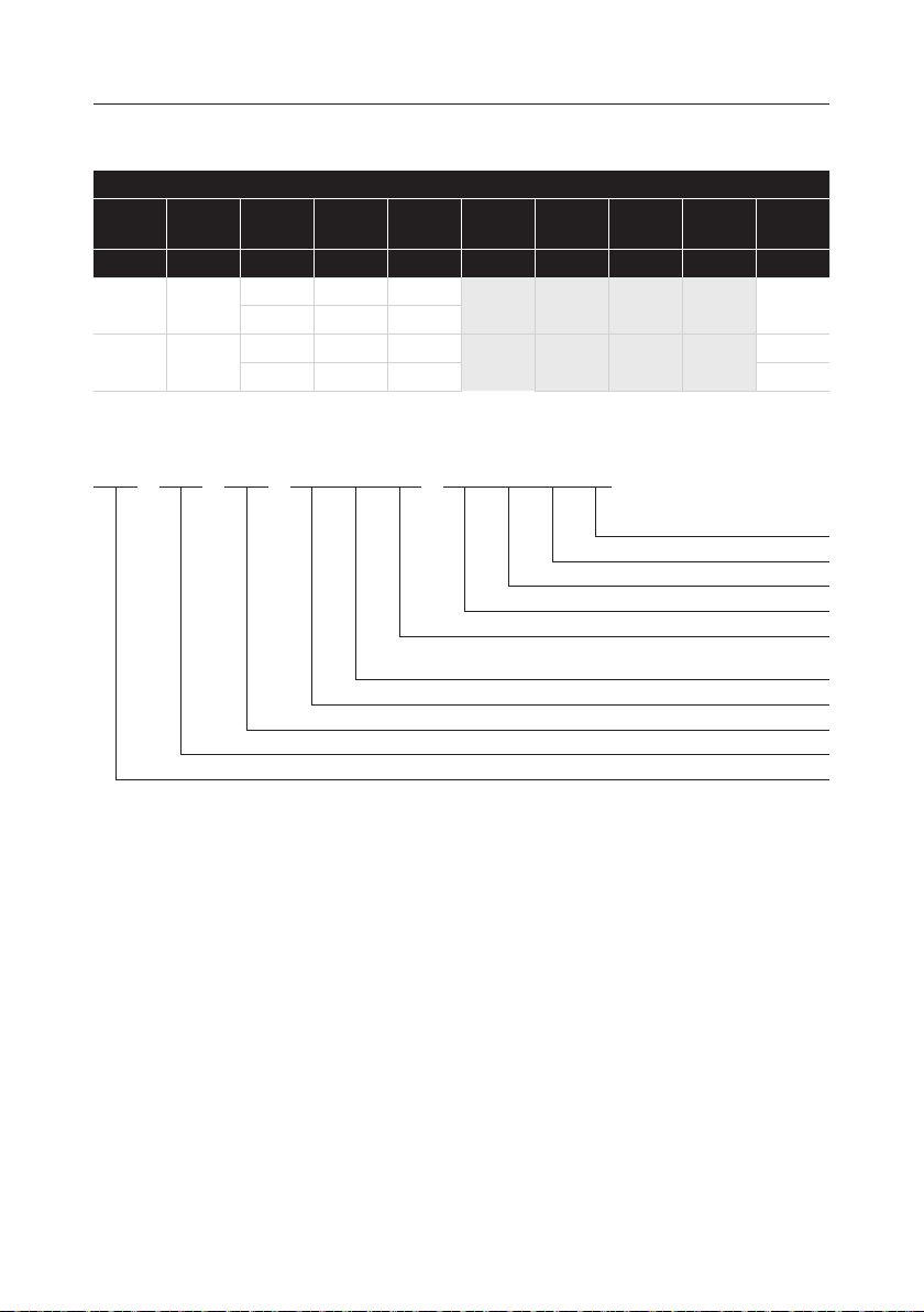
12.01 Product conguration table
GLS5.1 active lifter, congurations
Guldmann
lifter type
GLS5.1 (x) xxx x x x x x x x
GLS5.1 155 5 6
GLS5.1 155 5 6 1
Product
line
Load inkgCastors
type
205 5 6
205 5 6 1
Actuator
type
Additional
functions
Scale
module
CLM
module
Service
module
Example: GLS5.1 205 560 000
GLS5.1 205 5 6 0 0 0 0 0
N/A
N/A
N/A
N/A
N/A
Manual emergency down, motor
turned 90°
Castor size ø75/ø125 mm
Safe Working Load SWL: 205 kg
N/A
Lifter, type GLS5.1.1
User
interface
© Guldmann GB/US-1971/12/2019 • # 558351_2
21
Page 22
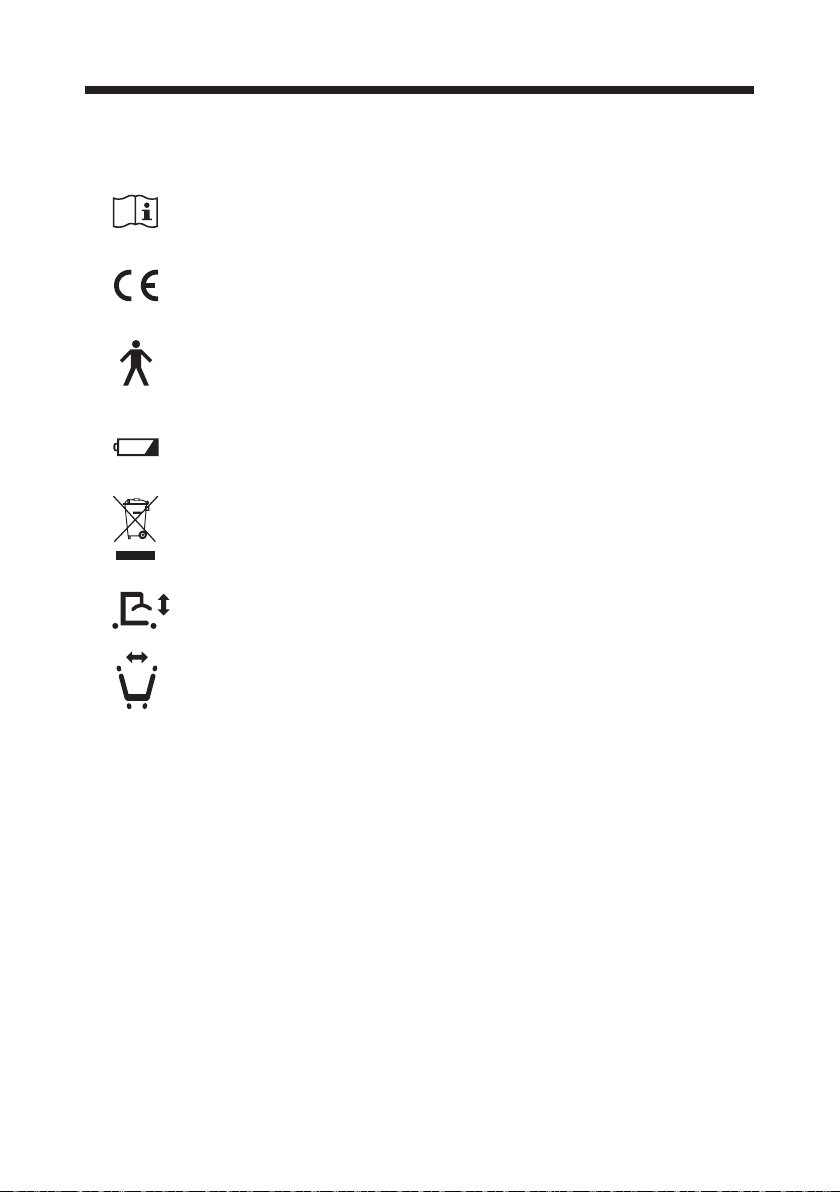
13.00 Labelling
Pictograms/labels used on product
Read the manual before use
CE-marking
Type B in accordance with EN 60601-1
Battery condition and charging
Must not be disposed of as standard household waste, but must be recycled.
Lifting boom vertical up and down movement
Leg spread movement
22
© Guldmann GB/US-1971/12/2019 • # 558351_2
Page 23
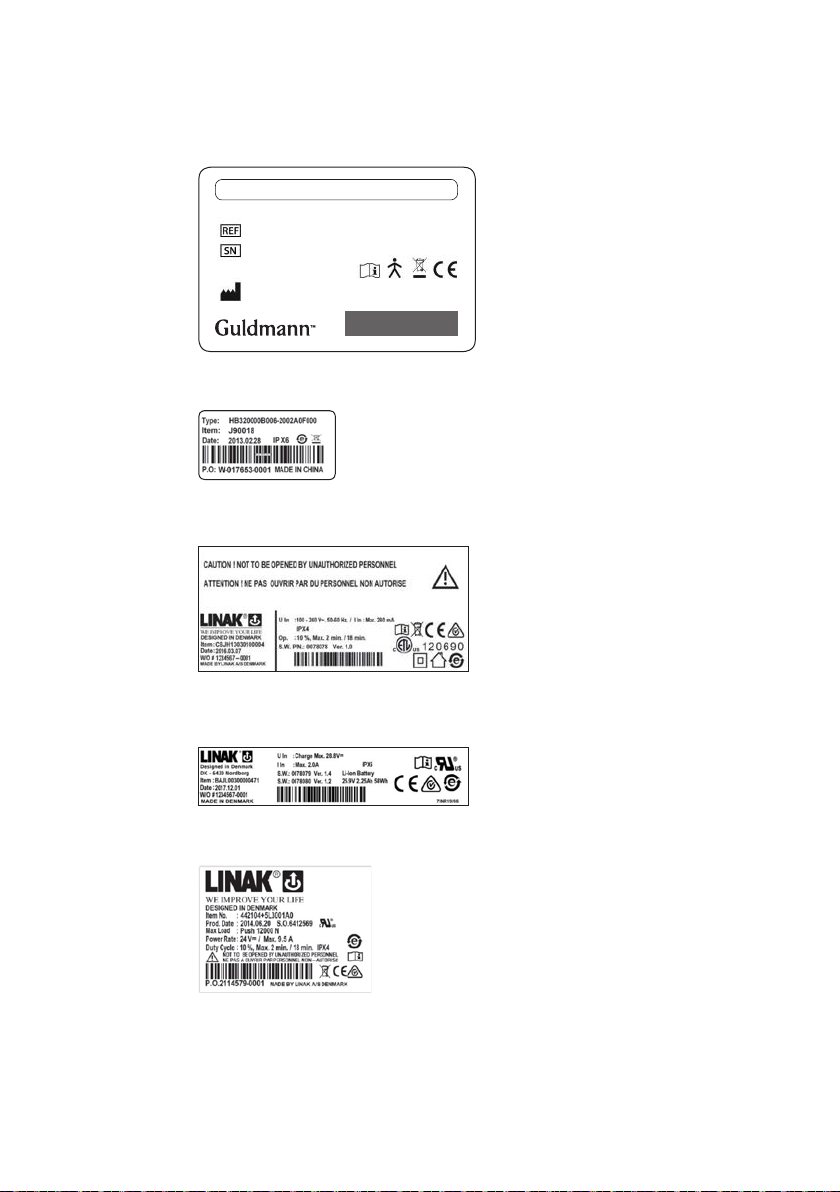
Examples of labels
Serial number label
GLS5.1 (xxxx) xxx xxx xxxx
max xxx kg / xxx lbs
xxxxxx
xxxxx
V. Guldmann A/S
Graham Bells Vej 21-23A
8200 Aarhus N, Denmark
Made in Denmark
yyyy-mm-dd
Duty Cycle max: 10% 2 min/18 min
Hand control
Control box
GS1-128
Battery
Actuator
© Guldmann GB/US-1971/12/2019 • # 558351_2
23
Page 24

14.00 EC-Declaration of conformity
The product is manufactured in compliance with the Council Directive
93/42/EEC of June 14th 1993, including amendments, as medical device
class 1.
15.00 Environmental policy statement - V. Guldmann A/S
Guldmann is continuously working towards ensuring that the company’s
impact on the environment, locally and globally, is reduced to a minimum.
It is Guldmann’s goal to:
• Comply with the current environmental legislation (e.g. WEEE and REACH
directives)
• Ensure that we, at the widest possible range, use RoHS compliant materials
and components
• Ensure that our products do not have an unnecessary negative impact on the
environment regarding use, recirculation or disposal
• Ensure that our products contribute to a positive working environment in the
places they are utilised
Inspections are made annually by the Department for Nature and Environment from the Municipality of Aarhus using the Danish Environmental Protection Act, section 42 as a reference.
16.00 EMC Information
Tabel 1
Guidance and manufacturer’s declaration – electromagnetic emissions
The GLS5.1 is intended for use in the electromagnetic environment specified below.
The customer or the user of the GLS5.1 should assure that it is used in such an environment.
Emissions test Compliance Electromagnetic environment – guidance
RF emissions
CISPR 11
RF emissions
CISPR 11
Harmonic emissions
IEC 61000-3-2
Voltage fluctuations/
flicker emissions
IEC 61000-3-3
Group 1 The GLS5.1 uses RF energy only for its internal function. Therefore,
Class B
Class A The GLS5.1 is suitable for use in all establishments, including do-
Complies
its RF emissions are very low and are not likely to cause any interference in nearby electronic equipment.
mestic establishments and those directly connected to the public
low-voltage power supply network that supplies buildings used for
domestic purposes.
24
© Guldmann GB/US-1971/12/2019 • # 558351_2
Page 25

Tabel 2
Guidance and manufacturer’s declaration – electromagnetic immunity
The GLS5.1 is intended for use in the electromagnetic environment specified below.
The customer or the user of the GLS5.1 should assure that it is used in such an environment.
IMMUNITY test IEC 60601
test level
Electrostatic
discharge (ESD)
±6 kV contact
±8 kV air
IEC 61000-4-2
±2 kV for power
supply lines
±1 kV for input/output
lines
Surge
IEC 61000-4-5
Voltage dips,
short interruptions and voltage
variations on
power supply
input lines IEC
61000-4-11
±1 kV line(s) to line(s)
±2 kV line(s) to earth
<5 % U
T
(>95 % dip in UT)
for 0,5 cycle
40 % U
T
(60 % dip in UT)
for 5 cycles
70 % U
T
(30 % dip in UT)
for 25 cycles
70 % U
T
(30 % dip in UT)
for 25 cycles
Power frequency
3 A/m 3 A/m The power frequency magnetic
(50/60 Hz)
magnetic field
IEC 61000-4-8
NOTE U
is the a.c. mains voltage prior to application of the test level.
T
Compliance level Electromagnetic environment
– guidance
±6 kV contact
±8 kV air
Floors should be wood, concrete
or ceramic tile. If floors are covered
with synthetic material, the relative
humidity should be at least 30 %.
±2 kV for power
supply lines
±1 kV for input/output
Mains power quality should be that
of a typical commercial or hospital
environment.
lines
±1 kV differential mode
±2 kV common mode
Mains power quality should be that
of a typical commercial or hospital
environment.
<5 % U
T
(>95 % dip in UT)
for 0,5 cycle
40 % U
T
(60 % dip in UT)
for 5 cycles
70 % U
T
(30 % dip in UT)
Mains power quality should be
that of a typical commercial or
hospital environment. If the user
of the GLS5.1 requires continued
operation during power mains
interruptions, it is recommended
that the GLS5.1 be powered from
an uninterruptible power supply or
a battery.
for 25 cycles
<5 % U
T
(>95 % dip in UT)
for 5 s
field should be measured in the
intended installation location to
assure that it is sufficiently low.
© Guldmann GB/US-1971/12/2019 • # 558351_2
25
Page 26
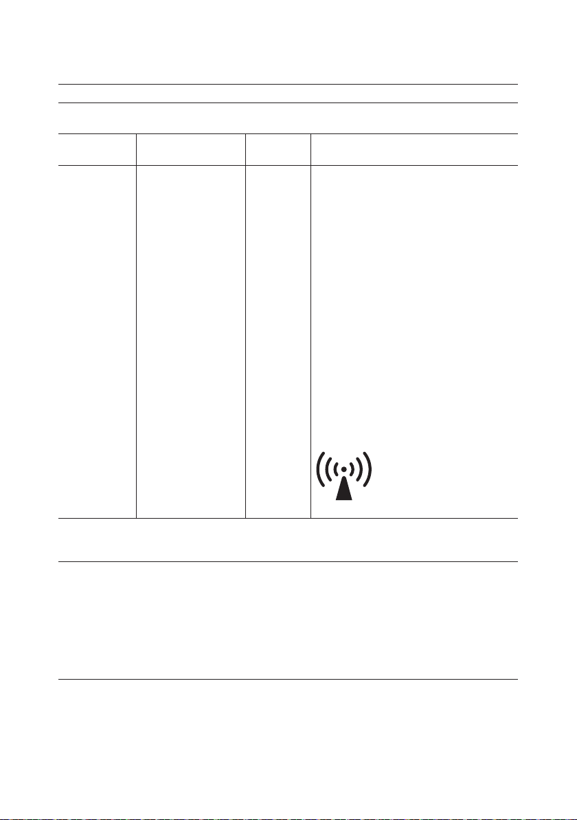
Tabel 4
Guidance and manufacturer’s declaration – electromagnetic immunity
The GLS5.1 is intended for use in the electromagnetic environment specified below.
The customer or the user of the GLS5.1 should assure that it is used in such an environment.
IMMUNITY test IEC 60601 TEST
LEVEL
Conducted RF
IEC 61000-4-6
Radiated RF
IEC 61000-4-3
3 Vrms
150 kHz to 80 MHz
3 V/m
80 MHz to 2,5 GHz
Compliance
level
3 Vrms
3 V/m
Electromagnetic environment
– guidance
Portable and mobile RF communications
equipment should be used no closer to any
part of the GLS5.1, including cables, than the
recommended separation distance calculated
from the equation applicable to the frequency of
the transmitter.
Recommended separation
distance
d=1,2√Pd=1,2√P 80 MHz to 800 MHz
d=2,3√P 800 MHz to 2,5 GHz
Where P is the maximum output power rating
of the transmitter in watts (W) according to the
transmitter manufacturer and d is the recommended separation distance in meters (m).
Field strengths from fixed RF transmitters, as
determined by an electromagnetic site survey
should be less than the compliance level in each
frequency range
b)
Interference may occur in the vicinity of equipment marked with the following symbol:
a)
NOTE 1 At 80 MHz and 800 MHz, the higher frequency range applies.
NOTE 2 These guidelines may not apply in all situations. Electromagnetic propagation is affected by
absorption and reflection from structures, objects and people.
a)
Field strengths from fixed transmitters, such as base stations for radio (cellular/cordless) telephones and
land mobile radios, amateur radio, AM and FM radio broadcast and TV broadcast cannot be predicted
theoretically with accuracy. To assess the electromagnetic environment due to fixed RF transmitters, an
electromagnetic site survey should be considered. If the measured field strength in the location in which the
GLS5.1 is used exceeds the applicable RF compliance level above, the GLS5.1 should be observed to verify
normal operation. If abnormal performance is observed, additional measures may be necessary, such as
re-orienting or relocating the GLS5.1.
b)
Over the frequency range 150 kHz to 80 MHz, field strengths should be less than 3 V/m.
26
© Guldmann GB/US-1971/12/2019 • # 558351_2
Page 27
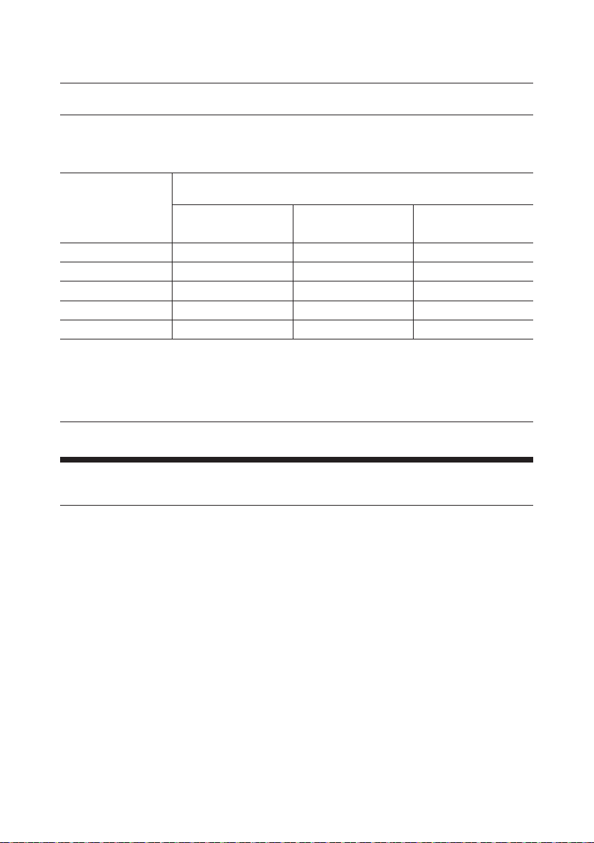
Tabel 6
Recommended separation distances between
portable and mobile RF communications equipment and the GLS5.1
The GLS5.1 is intended for use in an electromagnetic environment in which radiated RF disturbances are controlled. The customer or the user of the GLS5.1 can help prevent electromagnetic interference by maintaining
a minimum distance between portable and mobile RF communications equipment (transmitters) and the
GLS5.1 as recommended below, according to the maximum output power of the communications equipment.
Rated
maximum
output power
of transmitter
W
0,01 0,12 0,12 0,23
0,1 0,38 0,38 0,73
1 1,2 1,2 2,3
10 3,8 3,8 7,3
100 12 12 23
For transmitters rated at a maximum output power not listed above, the recommended separation distance d
in meters (m) can be estimated using the equation applicable to the frequency of the transmitter, where P is
the maximum output power rating of the transmitter in watts (W) according to the transmitter manufacturer.
NOTE 1 At 80 MHz and 800 MHz, the separation distance for the higher frequency range applies.
NOTE 2 These guidelines may not apply in all situations. Electromagnetic propagation is affected by absorption and reflection from structures, objects and people.
Separation distance according to frequency of transmitter
150 kHz to 80 MHz
d=1,2√P
80 MHz to 800 MHz
d=1,2√P
m
800 MHz to 2,5 GHz
d=2,3√P
17.00 Warranty and service conditions
A. Warranty
© Guldmann GB/US-1971/12/2019 • # 558351_2
Guldmann warrants its equipment is free from material defects under normal
use, and will perform substantially in accordance with the specications set
forth in documentation provided with the equipment.
This express warranty shall be in eect for one year from the date of original
purchase and installation (the “Warranty Period”). If a valid claim is made
during the Warranty Period for malfunction or equipment defect, Guldmann will
repair or replace the equipment at no additional cost to you. Guldmann retains
sole discretion as to whether the equipment will be repaired or replaced.
The warranty does not cover any part of the equipment that has been subject
to damage or abuse by the user or others. The warranty does not cover any
part of the equipment that has been altered or changed in any way by the
user or others. Guldmann does not warrant that the lifting device functions will
meet your requirements, be uninterrupted or error free.
The warranty set forth is in lieu of all other express and implied warranties, whether oral, written or implied, and the remedies set forth above are
your sole and exclusive remedies. Only an authorized ocer of Guldmann
27
Page 28

may make modications to this warranty, or additional warranties binding on
Guldmann. Accordingly, additional statements such as advertising or presentations, whether oral or written, do not constitute warranties by Guldmann.
This warranty shall be null and void if the equipment is operated and maintained in any manner inconsistent with its intended use or the instructions
provided with the product. Further, in order for the warranty to remain in eect
for the full Warranty Period, all service to the equipment must be provided
by a Guldmann certied technician. Any parts or components repaired or replaced by a Guldmann certied technician will be guaranteed for the remain-
der of the Warranty Period.
Only for USA
This warranty shall be null and void if the equipment is operated and maintained in any manner inconsistent with its intended use or the instructions
provided with the product. Further, in order for the warranty to remain in eect
for the full Warranty Period, all service to the equipment must be provided
by a Guldmann Certied Technician. A Guldmann Certied Technician is a
technician who has successfully completed Guldmann Service Training, and
who holds a valid Service Training Certicate from Guldmann, and is in possession of a valid password to access Guldmann’s Service and Information
Console (SIC). A Guldmann Service Training Certicate and SIC password
are valid for three years (only USA) from the date the technician is rst certied. Thereafter, the technician must undergo re-certication training to obtain
a new valid certicate and password. Any parts or components repaired or
replaced by a Guldmann Certied Technician will be guaranteed for the re-
mainder of the Warranty Period. In the event the warranty is rendered null
and void, the purchaser shall indemnify and hold Guldmann harmless of and
from any and all claims or liability arising as a result of equipment malfunction
or misuse.
B. Service or Repair
Contact Guldmann Repair for an authorization to return any defective item
during the Warranty Period. You will be provided with a return authorization
number and address for returning the item for warranty service or replacement. Do not return items to Guldmann under warranty without receiving a
Return Authorization Number.
If mailing the item, pack it carefully in a sturdy carton to prevent damage.
Include your Return Authorization Number, a brief description of the problem
and your return address and phone number. Guldmann does not assume the
risk of loss or damage while in transit, so it is recommended you insure the
package.
28
© Guldmann GB/US-1971/12/2019 • # 558351_2
Page 29

© Guldmann GB/US-1971/12/2019 • # 558351_2
29
Page 30

30
© Guldmann GB/US-1971/12/2019 • # 558351_2
Page 31

© Guldmann GB/US-1971/12/2019 • # 558351_2
31
Page 32
© Guldmann GB/US-1971/12/2019 • # 558351_2
V. Guldmann A/S
Corporate Oce:
Tel. +45 8741 3100
[email protected]
www.guldmann.com
Guldmann Inc.
Tel. 800 664 8834
Tel. 813 880 0619
Fax 813 880 9558
[email protected]
www.guldmann.net
 Loading...