

Guldmann GH3, GH3 Twin, GH3 Twin Series, GH3 Twin 500 Series, GH3 Twin 250 Series User Manual
GB/US ....GH3 Twin Ceiling Hoist
Vers. 9.00
1
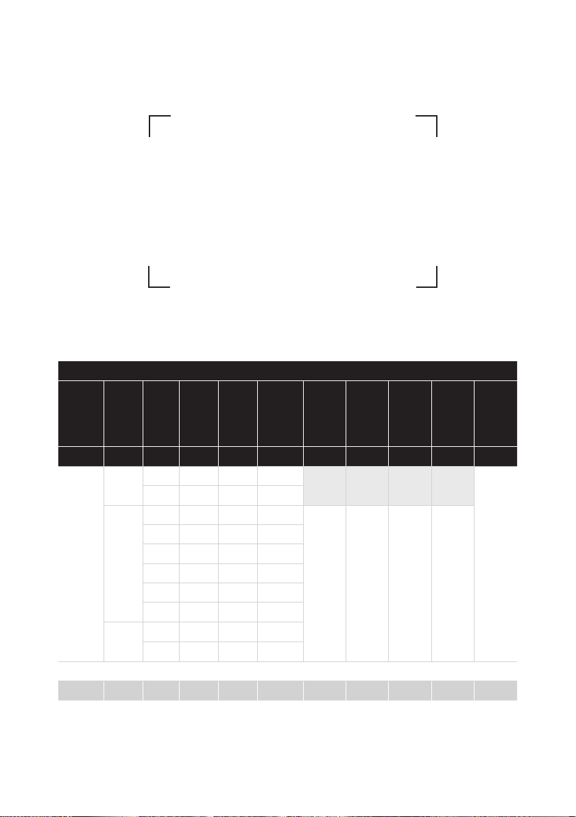
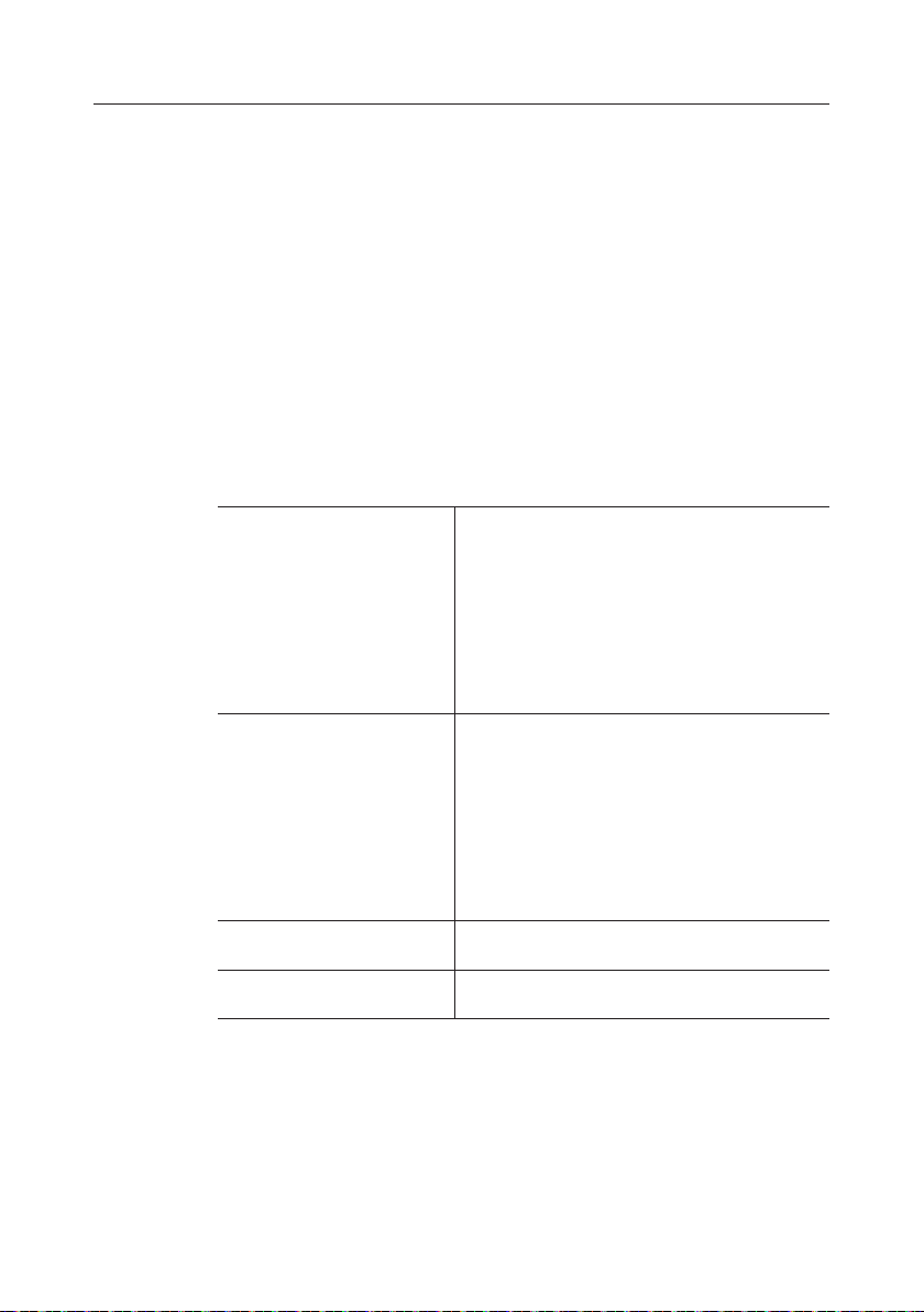
GH3 Lifting modules, congurations
Guldmann
hoist type
GH3 (x) xxx x x x (x) x x x x
GH3 200 1 1 0 - 1 - 2 Hand
GH3 X Y Z Z Z Q Q Q Q Q
Product
Load inkgNumber
line
250 1 1 0 - 1 - 2
+ 250 1 1 0 - 1 - 2 None:
275 1 1 0 - 1 - 2
300 1 2 0 - 2
350 1 2 0 - 2
375 1 2 0 - 2
400 1 2 0
Twin 250 2 2 0
500 2 2 0
of lifting
straps
Number
of lifting
motors
Number of
horizontal
drive
motors
WIFI
module
empty
WIFI: 1
Scale
module
None: 0
Scale: 1
Class III
Scale: 2
CLM
module
None: 0
CLM: 1
Service
module
None: 0
Service: 1
User
interface
control: 0
IR: 1
2
© Guldmann GB/US- 12/2018 • # 550383_9.00

GH3 Twin Ceiling Hoist
Item nos:
552xxx
1.00 .........Purpose and use ..............................................5
1.01 .........Manufacturer ..................................................5
1.02 .........Intended use ..................................................5
1.03 .........Conditions for use ..............................................5
1.04 .........Important/Precautions ...........................................6
1.05 .........Load limits on GH3 system .......................................7
1.06 .........Unpacking and Preparation .......................................7
1.07 .........Placing a new GH3 Hoist in an existing rail system ....................7
1.08 .........Power supply ..................................................8
1.09 .........Installation of GH3 Cross hanger and Horizontal lifter ..................9
1.10 .........Lifting sling ...................................................11
2.00 .........Description of functions .......................................12
2.01 .........Pictograms ...................................................12
2.02 .........Indicator lamps and audio signals .................................13
2.03 .........Operation ....................................................14
2.04 .........Supplementary modules, GH3+. . . . . . . . . . . . . . . . . . . . . . . . . . . . . . . . . . . 16
2.05 .........Conguration of supplementary modules, GH3 .......................20
2.06 .........Important before using the Scale module and Class III scale ............21
2.07 .........Scale module (GH3+ with integrated scale module) ..................22
2.08 .........Class III Scale (GH3+ with Class III Scale) ..........................25
2.09 .........Calibration/verication of Classe III Scale ...........................30
2.10 .........CLM module (GH3 with statistical function for management use) ........31
2.11 .........Service module (GH3 with service module) .........................33
2.12 .........Safety functions ...............................................35
2.13 .........Charging/connection ...........................................37
2.14 .........Accessories ..................................................37
3.00 .........Environmental conditions ......................................38
4.00 .........Maintenance and storage ......................................39
4.01 ........Cleaning and disinfection ........................................39
4.02 .........Storage .....................................................39
4.03 .........How to prevent/avoid corrosion? ..................................39
4.04 .........The owner’s daily maintenance duty ...............................40
4.05 ........Disposal of the GH3 including batteries ............................40
5.00 ........Service and lifetime ...........................................40
5.01 .........Lifetime .....................................................40
5.02 .........Safety/service inspections .......................................40
5.03 .........Troubleshooting ...............................................41
© Guldmann GB/US-12/2018 • # 550383_9.00
3

6.00 .........Classication ................................................41
7.00 .........Certicates ..................................................43
8.00 .........Technical specications .......................................43
9.00 .........EC-Declaration of conformity ...................................46
10.00 ........Type approval certicate .......................................47
11.00 ........Environmental policy statement - V. Guldmann A/S ................48
12.00 ........EMC Information .............................................48
. . . . . . . . . . . . . USA and countries outside the EU ..............................52
. . . . . . . . . . . . . A. Users guide ...............................................52
. . . . . . . . . . . . . B. WARRANTY ...............................................52
4
© Guldmann GB/US- 12/2018 • # 550383_9.00

1.00 Purpose and use
1.01 Manufacturer
V. Guldmann A/S
Graham Bells Vej 21-23A
DK-8200 Aarhus N
Tel. + 45 8741 3100
Fax + 45 8741 3131
www.guldmann.com
1.02 Intended use
The GH3 Twin (hereafter called GH3) is a ceiling-mounted hoist, which covers
the requirements for heavy and special lifting or moving of persons.
GH3 is intended for use in professional healthcare facility environments
where operators with medical training are continually available.
1.03 Conditions for use
The use of the GH3 is subject to the following:
• The GH3 should only be used by trained personnel.
• The maximum nominal load, 250 kg (550 lbs), 500 kg (1100 lbs), respectively,
must not be exceeded.
• The instruction offered by Guldmann to all customer groups in connection
with the purchase of a ceiling-mounted hoist has been received.
• The helper pays attention to the well-being of the user when using the
hoist.
• The hoist is used in rail systems which are installed, tested and approved
according to Guldmann’s stipulation.
• Only technicians who have been certied by Guldmann may install and
test the rail systems.
• The hoist is used with the Guldmann lifting hanger or with other suitable
hanger (section 1.09).
• The hoist is used with a Guldmann lifting sling or with other suitable slings
(section 1.10).
© Guldmann GB/US-12/2018 • # 550383_9.00
5

1.04 Important/Precautions
• Read the instructions carefully before using the GH3 and in connection
with cleaning and service of the hoist.
• The GH3’s maximum load must never be exceeded.
• The GH3 may only be used to lift a person.
• The red strap for the emergency stop and the emergency lowering must
be adjusted to the helpers reach, and must not be removed.
• The GH3 must not be used where there is a risk of it being splashed with
water.
• If a defect appears during use of the GH3, stop using the hoist and contact
the Guldmann Service Team for repairs.
• The GH3 is controlled by a microprocessor PCB, which can be damaged by
static electricity if touched without the necessary precautions, (see point 1.08)
• The electronics may only be serviced by Guldmann approved service
technicians.
• The lifting hanger must not be mounted or replaced when the GH3 hoist is
positioned over the patient.
• Do not modify this equipment without authorization of the manufacture
• The GH3 needs special precautions regarding EMC and needs to be installed
and put into service according to the EMC information provided in Chapter 11
EMC Information.
• Portable and mobile RF communications equipment can affect the GH3.
• The use of ACCESSORIES, transducers and cables other than those
specied, with the exception of transducers and cables sold by Guldmann A/S
of the GH3 as replacement parts for internal components, may result in
increased EMISSIONS or decreased IMMUNITY of the GH3.
• The GH3 should not be used adjacent to or stacked with other equipment
and that if adjacent or stacked use is necessary, the GH3 should be observed
to verify normal operation in the conguration in which it will be used.
• Transport of this equipment should only be undertaken after conditions
described in section 3.00 (Environmental conditions).
Re: EMC
If electromagnetic or other inuences occur between this product and other
products, these products must not be used together.
6
© Guldmann GB/US- 12/2018 • # 550383_9.00
1.05 Load limits on GH3 system
Read the label which indicate the maximum load limits for each component.
The components, e.g. lifting hanger, lifting sling, etc. labelled with the lowest
load limit determines the maximum load limit for the entire system.
This maximum load limit must not be exceeded.
Please note that the max load may change when different components are
used, such as lifting hangers, lifting slings, etc.
1.06 Unpacking and Preparation
Visual check of the GH3.
If the GH3 is thought to be damaged upon reception, the GH3 must not be
used before it has been checked and approved by a qualied person or the
Guldmann Service Team.
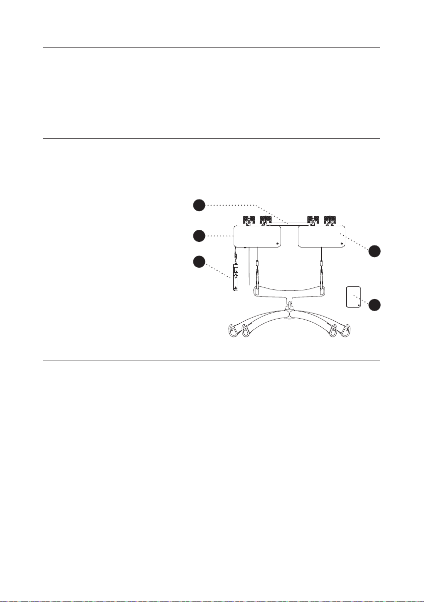
Contents of the box
5
1. GH3 hoist (leader)
2. GH3 hoist (follower)
3. Hand control
1
4. Transformer
5. Connector bar and cable
6. Manual (not illustrated)
3
7. Label for rail system
(not illustrated)
1.07 Placing a new GH3 Hoist in an existing rail system
Please notice, placing a new GH3 hoist in an existing rail system it must
be ensured that:
• The rated max load of the rail system, must be equal or higher than the
max load of the new hoist.
– If there is no max load mentioned on the rail system, the rail system
must then be checked according to the guideline in the Installation
guide (distance between bracket according to max load)
– If the brackets are not visible, then a load test with 1,5 x max load of
the hoist must be performed minimum 20 min. The deection of rails must
not be higher than 1/200 of the length of the rail.
– If it is not possible to do any of the above mentioned, please contact
Guldmann or their representative.
2
4
• If the rail system can not be rated to the same max load as the hoist,
then extra brackets must be installed according to the Installation
guide (distance between bracket according to max load).
© Guldmann GB/US-12/2018 • # 550383_9.00
7

Class I equipment
Fixed rail systems are class I equipment and must be installed by a qualied
technician or by Guldmann Service Team.
Equipment is disconnected from Supply Mains by breaking the mains breaker
switch.
Emergency stop device
The emergency stop device must be reset in order to connect power to the
product. To do this, push the yellow reset button (see point 2.09).
1.08 Power supply
GH3 is equipped with batteries that require regular recharging. The power
supply for charging and the battery charging point must be connected by a
qualied engineer or by Guldmann Service Team.
The transformer supplied must always be used.
Safety concerning static electricity (ESD)
Service technicians and installers must use an ESD-safety package
consisting of a mat, a ground wire, and a bracelet. The technician/installer
connects the mat to a grounding point. The technician/installer must then
put on the bracelet and connect it to the mat. If it is not possible to nd a
grounding point, the mat and the bracelet must be used as a minimum.
Only then is it allowed to work with the PCB Board or components where it is
possible to come into contact with the PCB Boar
8
© Guldmann GB/US- 12/2018 • # 550383_9.00
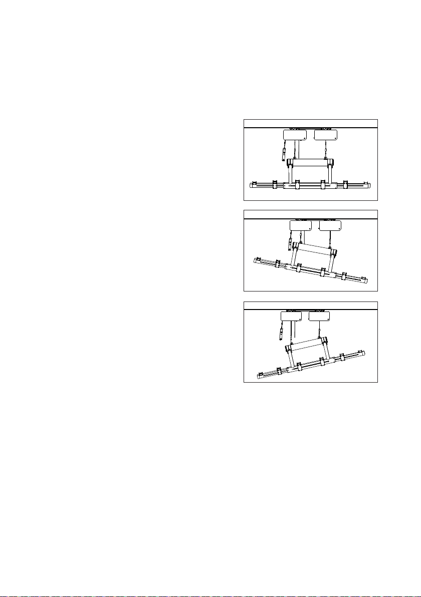
1.09 Installation of GH3 Cross hanger and Horizontal lifter
Lifting hangers from other manufacturers
Guldmann shall not be liable for faults or accidents that may occur as a result
of using lifting hangers made by other manufacturers.
If there is any doubt about the selection or use of a lifting hanger,
please contact your supplier.
The lifting hanger can be installed to the lifting strap without the use of any
tools.
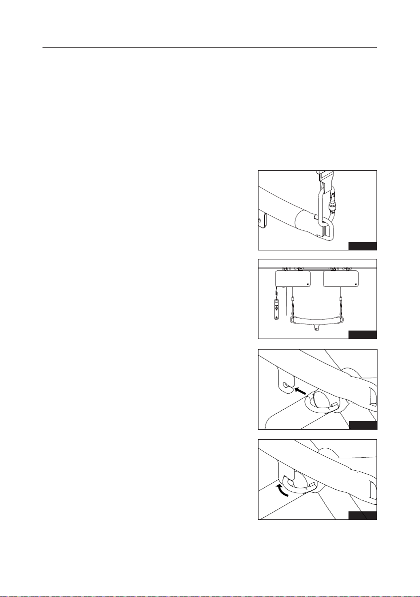
Installation of GH3 Cross
lifting hanger
1.
Start with the installation of the GH3 lifting
beam. Place each of the lifting straps oval
hook in the eye of the GH3 lifting beam,
one on each side (Fig. 1 and 2).
Important:
Check that none of the lifting straps
are twisted after the installation of the
lifting beam and ensure that the lifting
beam is horizontal during the lift!
Fig. 1
Fig. 2
2. Tilt GH3 Cross hanger to slide the round
hoop in to the hook (Fig. 3)
3. Turn the at part of the Hoop out of
the hook before lowering the GH3
Cross hanger to horizontal position
(Fig. 4 and 5)
© Guldmann GB/US-12/2018 • # 550383_9.00
Fig. 3
Fig. 4
9
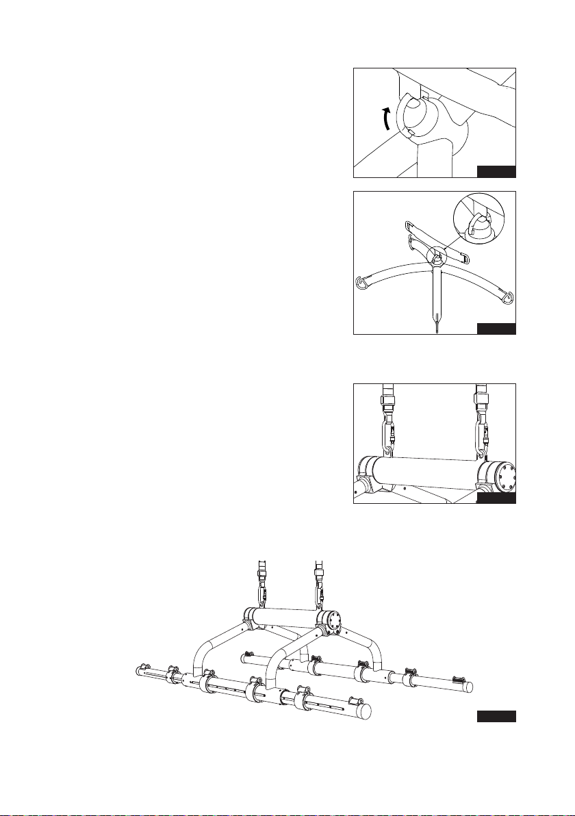
5. The GH3 Cross hanger is ready to use,
when it is able to move freely in a
horizontaI position (Fig. 6)
Installation of GH3 Horizontal lifter
Use the oval hook to install the Horizontal
lifter. (Fig. 7 and 8)
Important:
Check that none of the lifting straps are
twisted after the installation of the GH3
Horizontal lifter
Fig. 5
A
Fig. 6
Fig. 7
Fig. 8
10
© Guldmann GB/US- 12/2018 • # 550383_9.00

1.10 Lifting sling
A lifting sling with four to six lifting straps designed for mounting on hooks
should be used when using a Guldmann lifting hanger. Place the straps on
the hooks.
Slings made by other manufacturers
Guldmann shall not be liable for faults or accidents that may occur as a
result of using lifting slings made by other manufacturers.
If there is any doubt about the selection or use of a lifting sling,
please contact your supplier.
Guldmann shall not be liable for faults or accidents due to incorrect use of
the lifting sling, or for reasons of inadequate attention on the part of the carer
or user.
Working with the GH3
The GH3 runs easily in the rail system and does not have any special
requirements for space or power in connection with moving. Attention can
thus be fully focused on the user’s functional level and the helper’s technique.
If the hoist is used correctly, the user should only be lifted to the extent that
she/he is clear of the surface and should be moved at this height.
Attaching the lifting sling to GH3 Cross hanger
Place the straps from the lifting sling on the hooks on the lifting hanger. Start
with the uppermost set of straps (from the back) and then take the lowest set
of straps (from the legs). Refer to section 2.14 Cross Hanger 550800 with
Connecting Bar 550544.
Attaching the lifting sheet to Horizontal lifter, foldable
Read the instructions in the user manual for the Horizontal lifter.
Important!
Only persons who have received competent instruction regarding the use of
lifting equipment and tting of slings should use the hoist.
Plan the move. Avoid leaving the user in the lifting sling unattended.
The hoist lifts quickly and powerfully. Before lifting, check that the user is
completely free of his/her surroundings. The user’s head, arms, hands and
feet must not be in danger of becoming trapped. Be careful with any tubes
and wires that are attached to the user. The user should not hold the lifting
strap during the moving procedure as there is a risk of crushing between
the strap’s hook and the hoist. Check that the hand control and hand control
cable is free of hanger, patient and other object before the hoist is activated
up or down moved.
If the hoist is used correctly, the user should only be lifted to the extent that
she/he is clear of the surface and should be moved at this height.
© Guldmann GB/US-12/2018 • # 550383_9.00
11
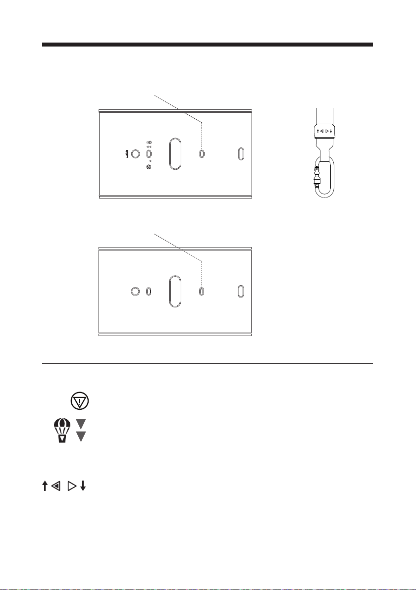
2.00 Description of functions
Information panel on the GH3 bottom surface on leader hoist.
Lamp indicator Information on strap
Information panel on the GH3 bottom surface on follower hoist.
Lamp indicator
2.01 Pictograms
Emergency stop
Emergency lowering function
Reset emergency stop
RESET
Tilt function
12
© Guldmann GB/US- 12/2018 • # 550383_9.00
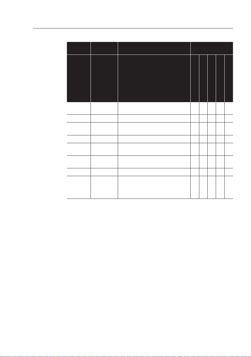
2.02 Indicator lamps and audio signals
Status Indicator
Off
Off
lamps
Audio signals Possible GH3
Functions
Up
Down
Emergency lowering
Horizontal drive motor
– stand by
All OK Green x x x x x
No charging Yellow,
3 x Beep after 60 sec x x x x x
after 15 sec
Low battery Yellow x x x x x
Fault on
Yellow Beeps at button activation x x
hoist
Battery
critically low
Yellow Beeps at button activation
that is not permitted
x x x
Over load Yellow Beeps at button activation x x
Service date
Yellow Beeps at button activation x x x x x
exceeded
more than
x
)
60 days
x
) Only if the hoist is with Service modul
Communication
© Guldmann GB/US-12/2018 • # 550383_9.00
13
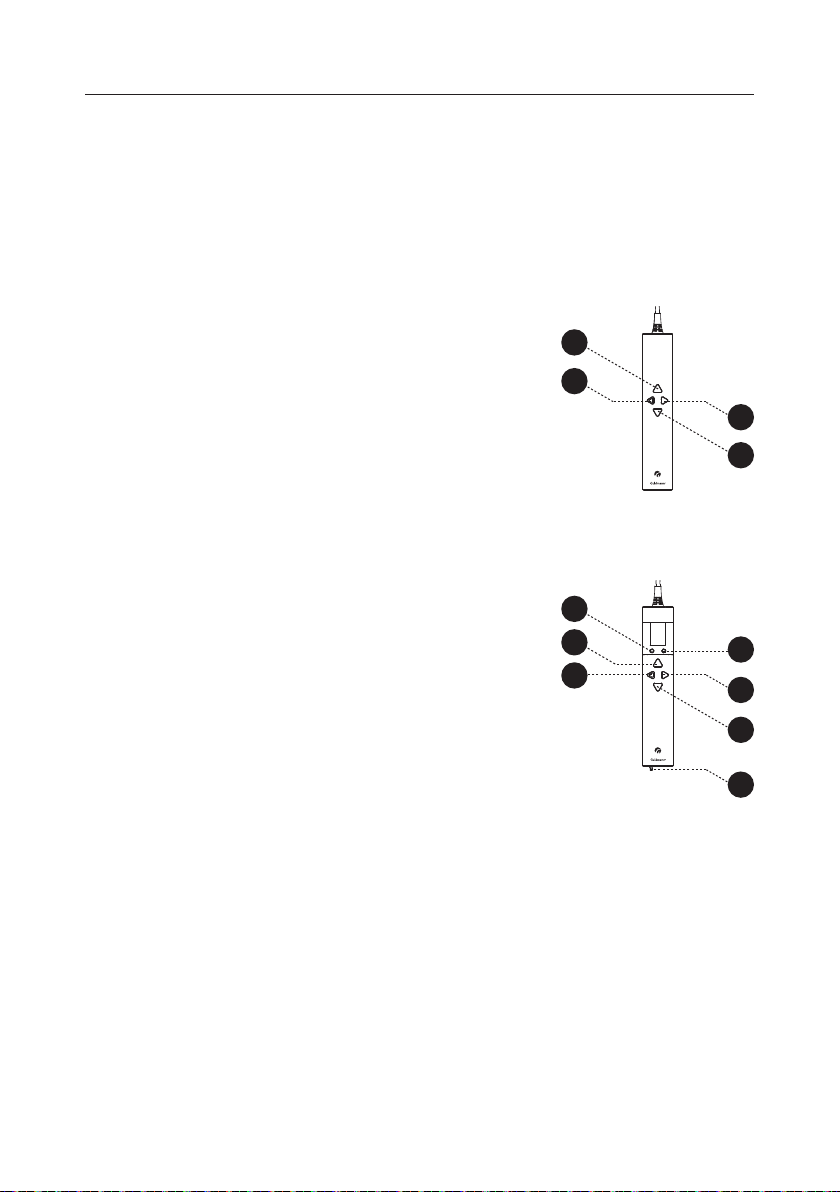
2.03 Operation
Hand control
The GH3 is switched on automatically when
a button on the hand control is pressed.
The GH3 is switched off automatically after
approx. 8 minutes without activation.
GH3
1. Lift
2. Lower
3. Lift leader hoist. (Tilt fuction)
4. Lower leader hoist. (Tilt fuction)
GH3 with sumplementary modules
1. Lift
2. Lower
3. Lift leader hoist. (Tilt fuction)
4. Lower leader hoist. (Tilt fuction)
5. Function selection button
(section 2.05, supplementary modules)
6. Function selection button
(section 2.05, supplementary modules)
7. PDA interface (mini USB) x)
PDA /Netbook
1
3
4
2
5
1
3
6
4
2
7
x) Accessories to CLM module
(see Supplementary modules, GH3 (section 2.04))
14
© Guldmann GB/US- 12/2018 • # 550383_9.00
Using tilt function on GH3
The GH3 has a tilt function. This function can only be used with
a horizontal lifter. (See section 2.03 for positions of hand control buttons)
1. When the buttons 1 or 2 are pressed
both hoists will lift or lower the
horizontal lifter.
2. When the button 3 is pressed only the
leader hoist lifts the horizontal lifter.
3. When the button 4 is pressed only the
leader hoist will lower the horizontal
lifter.
© Guldmann GB/US-12/2018 • # 550383_9.00
15
Setup
Setup
Change
Language
English
OK
Change
Language 1-8
Dansk
OK
Change
Language 2-8
Deutsch
OK
Change
Language 3-8
Svenska
Change
Units
KG
Change
Units
lbs
Change
Units
KG
OK
OK
2.04 Supplementary modules, GH3+
There are various supplementary modules for the GH3+
• CLM module (GH3+ with statistical function for management use)
• Service module (GH3+ with Service module)
• Scale module (GH3+ with integrated scale)
• Class III Scale (GH3+ with integrated Class III Scale)
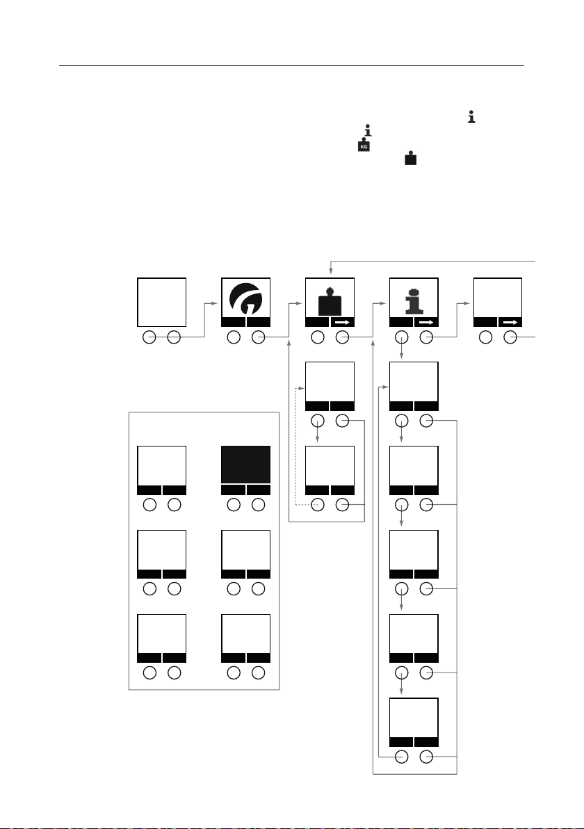
Menu structure, GH3/GH3+ with supplementary modules
• Scale module
• CLM module
• Service module
III
Next
service
2008.04.22
OK
Low battery
OK
No charging
OK
Pop-ups
Service date
exceeded
call service
Critical low
battery
Fault hoist
Scale
KG
OK
Start
Scale KG
248.0
ExitZero
Scale KG
0.0
Exit
OK
OK
ExitZero
CLM
Show
CLM 1-5
Lifetime
total lifts
987
ExitNext
CLM 2-5
Lifetime
heavy lifts
232
ExitNext
CLM 3-5
Last week
total lifts
60
ExitNext
CLM 4-5
Lifts per
week avg
72
ExitNext
CLM 5-5
Hoist ID
Hoist #1
ExitNext
Next service
2008.04.22
16
© Guldmann GB/US- 12/2018 • # 550383_9.00
Setup
Setup
Units
Change
Units
Change
Units
Change
lbs
Language
KG
English
Change
Language 1-8
Dansk
Change
OK
OK
Language 2-8
KG
OK
Deutsch
Change
OK
Language 3-8
Svenska
Change
OK
Language 4-8
Italianio
Change
OK
Language 5-8
Espanol
Change
OK
Language 6-8
Francaise
Change
OK
Language 7-8
Portuguese BR
Change
© Guldmann GB/US-12/2018 • # 550383_9.00
17

Scale
CLM
2008.04.22
Next service
Setup
Setup
Change
Language
English
OK
Change
Language 1-8
Dansk
OK
Change
Language 2-8
Deutsch
OK
Change
Language 3-8
Svenska
Scale Info 1-2
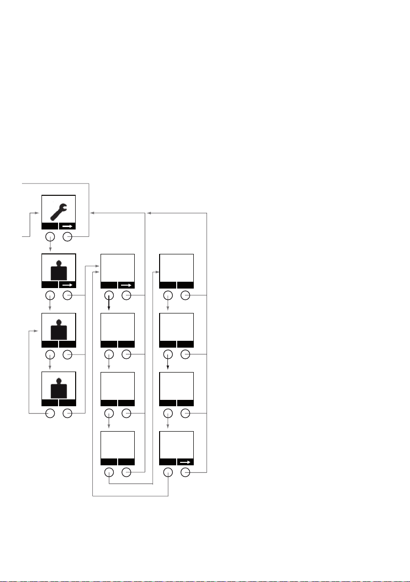
Menu structure, GH3/GH3+ with supplementary modules
• Class III Scale
• CLM module
• Service module
III
OK
Start
Next
Version
01.00
Show
Next
service
2008.04.22
OK
Low battery
OK
No charging
OK
Pop-ups
Service date
exceeded
call service
Exit
Critical low
battery
OK
Fault hoist
OK
Scale W1
80.3 kg
NET
ExitTa re
Scale W1
0.0 kg
NET
ExitTa re
Scale Info 2-2
Changes
001
CLM 1-5
Lifetime
total lifts
987
ExitNextExitNext
CLM 2-5
Lifetime
heavy lifts
232
ExitNext
CLM 3-5
Last week
total lifts
60
ExitNext
CLM 4-5
Lifts per
week avg
72
ExitNext
CLM 5-5
Hoist ID
Hoist #1
ExitNext
18
© Guldmann GB/US- 12/2018 • # 550383_9.00

2008.04.22
Next service
Setup
Setup
Language
English
Change
Language 1-8
Dansk
Change
Language 2-8
Deutsch
Change
Language 3-8
Svenska
Change
Language 4-8
Italianio
Change
OK
Language 5-8
Espanol
OK
Change
OK
Language 6-8
Francaise
OK
Change
OK
Language 7-8
Portuguese BR
OK
Change
© Guldmann GB/US-12/2018 • # 550383_9.00
19

2.05 Conguration of supplementary modules, GH3
Before the GH3 is put into use, the hoist must be congured. Conguration
covers language (Scale module/CLM module/Service module) and the unit for
specication of weight (Scale module).
Factory setting: Language: English (UK)
Unit of weight: kg
Scale module: The weight unit can be set to kg or lb.
Class III Scale: The weight is always shown in kg.
Conguration of supplementary modules takes place from the GH3
hand control.
Setting the language
Scale
KG
Menu Start
Statistics
Show
Next service
2008.04.22
Setup
Setup
1. Press any key on the GH3 hand control to activate the hoist.
When the hoist is activated, the display on the hand control is switched on
and the Guldmann logo “G” appears.
2. Select “Menu” using the function key located immediately below the display
and then select until the “Setup” menu appears in the display.
3. Select “Setup” and then until the “Language” menu appears in the
display.
4. Select “Change” until the preferred language appears in the display, and
conrm the selection by pressing “OK”.
5. Then return to “Setup”. Select to return to the start menu.
Language
English
Change
20
© Guldmann GB/US- 12/2018 • # 550383_9.00

2.06 Important before using the Scale module and Class III scale
Important/warning
• Read the user manual carefully before using the Digital Scale.
Safety instructions
• Please comply with the maximum capacity of the scale which is stated on the
identication plate on the back of the device.
The maximum load must not be exceeded. The safety requirements and
the notes on appropriate use must also be observed.
• Any modication exempts the supplier from liability for any damage as a
result of modication.
• It is strictly forbidden to carry out any repairs and soldering work on the
motherboards or to replace any components. Repairs must only be
undertaken by persons who are authorized and qualied to do so.
The following applies to Class III scales:
• Sealing label (communication module) may not be broken
• The scale must be re-veried by a Notied Body, cf. local legislation for
maintaining medical approval. If necessary, a Guldmann-approved service
technician can calibrate the scale in connection with the a Notied Body’s reverication.
• When ordering a Class III scale, indicate the exact operating address (zip code,
city, country). The specic G factor at the place of operation is coded into the
scale’s software, and the scale may only be used at this exact location.
Shock effects
The GH3+ with scale module includes high-sensitive sensors to register mass
corresponding to the nominal recommended load. The sensors are highly
sensitive and can be damaged by the effects of shock, for example pulling
the GH3+ at extreme speed into an end stop.
Operation
Always reset the GH3+ scale module before weighing takes place. When
resetting the unit, the lifting hanger and the desired lifting sling must be
attached under the hoist.
Never pull the hand control wire while weighing.
Important
The power conserving function will automatically turn off the display after
30 seconds when there is no weight on the scale. This can be changed
– see section 3.07.
© Guldmann GB/US-12/2018 • # 550383_9.00
21

2.07 Scale module (GH3+ with integrated scale module)
The GH3+ with scale module (option) provides the facility to determine the
user’s weight.
Warning!
If the scale is required to comply with the Non-automatic weighing instruments directive (EU Directive 2014/31/EU), a Class III scale must be used.
Setting the units, kg/lbs (Scale module)
Scale
KG
Menu Start
Statistics
Show
Next service
2008.04.22
Setup
Setup
1. Press any key on the hand control to activate the hoist.
When the lifting module is activated, the display on the hand control is
switched on and the Guldmann logo “G” appears.
2. Select “Menu” using the function key located below the display
3. Then select until the “Setup” menu appears in the display.
4. Select “Setup” and then until the “Units” menu appears in the display.
5. Select “Change” to switch between the units kg and lbs, and conrm the
selection by pressing “OK”.
6. Select to return to the start menu.
7. The display in the hand control switches off automatically after use
(approx. 8 min). (See the complete menu summary, section 2.04,
Supplementary modules, GH3)
Scale
KG
Change
22
© Guldmann GB/US- 12/2018 • # 550383_9.00

Resetting the unit (tara)
Scale
KG
Menu Start
Scale KG
248.0
ExitZero
Scale KG
0.0
ExitZero
1. Press any key on the hand control to activate the hoist.
When the lifting module is activated, a display on the hand control is
switched on and the Guldmann logo “G” appears.
2. Select “Menu” using the function key located immediately below the
display
3. Then select until the “Scale” menu appears in the display.
4. Then select “Start”.
5. Park the hand control on the lifting hanger. (If the helper pulls the hand
control during weighing, this will affect the result of the weighing process).
6. When the lifting hanger with the lifting sling is at rest, select “Zero”
to reset the GH3+ scale module.
The scale module has now been reset and weighing can commence.
© Guldmann GB/US-12/2018 • # 550383_9.00
23

Weighing
Scale
KG
Menu Start
Scale KG
248.0
ExitZero
1. Always reset the GH3 scale module before weighing takes place, see
section entitled “Resetting the unit”.
2. Place the lifting sling on the user and attach it to the lifting hanger.
3. Lift the user with care.
4. Park the hand control on the lifting hanger.
5. Select “Menu” using the function key located immediately below the
display and then select until the “Scale” menu appears in the display.
6. Then select “Start”.
7. When the sling and the user are at rest and hanging freely, the current
weight can be read on the display. (The weight can be read to an accuracy
of 1 decimal place).
8. Select “Exit” to return to the main menu.
Note:
The display in the hand control switches off automatically after use
(approx. 8 min.)
24
© Guldmann GB/US- 12/2018 • # 550383_9.00

2.08 Class III Scale (GH3+ with Class III Scale)
The GH3+ with scale module (option) provides the facility to determine the
III
user’s weight.
Description
A Class III scale is a built-in digital scale that satises the requirements for
medical weighing tasks with calibrated, accurate and repeatable weight
measurements with Class III precision in accordance with EU Directive
2014/31/EU. Available from Aug./Sep. 2018.
Resetting is performed electronically with the push of a button, which makes
it fast and easy for the operator to weigh the patient.
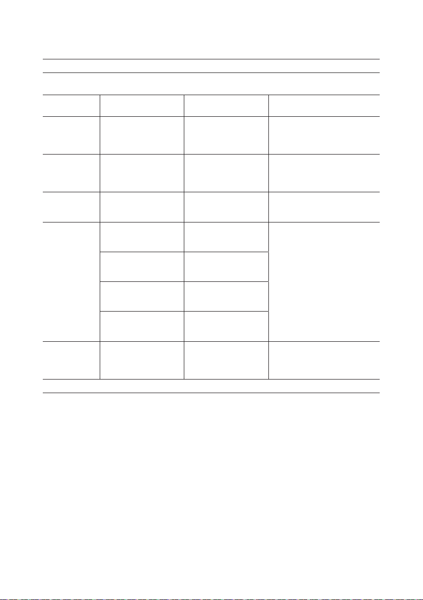
The scale’s precision
The scale weighs with different levels of accuracy in two weighing ranges and
depending on whether a single or twin hoist is used.
Product
variants
Maximum
capacity
e
1
Min
1
Max
1
n
1
e
2
Min
2
Max
2
GH3
GH3
GH3
GH3
GH3
+
200
kg
+
250
kg
+
275
kg
+
300
kg
+
350
kg
GH3
+
375
kg
200 kg250 kg275 kg300 kg350 kg375 kg400 kg250 kg500kg700
0,1 kg 0,2 kg
2 kg 4 kg
200 kg 200 kg
2000 1000
0,2 kg 0,5 kg
4 kg 10 kg
250 kg275 kg300 kg350 kg375 kg400 kg250 kg500 kg700
N/A
GH3
+
400
kg
GH3
+
Twin
250
kg
GH3
+
Twin
500
kg
GH3
+
Twin
700
kg
kg
kg
The specic weighing ranges and accuracy that apply to the individual hoist
are indicated on the hand control immediately above the display:
W1 xxx xxx xxx
W2 xxx xxx xxx
© Guldmann GB/US-12/2018 • # 550383_9.00
e = kg Min kg Max kg
25
Resetting (tare) of the Class III scale
W1
W1
W1
Scale
Tar e
- - -
Scale
►0◄
Tar e
0.0 kg
Scale
7.6 kg
Tar e
Menu
Scale
III
Start
1. Press any key on the hand control to activate the hoist.
Guldmann logo “G” appears in the display.
Select “Menu” using the function key located immediately below the display.
2. Then select until the “Scale” menu appears in the display.
Then select “Start”.
3. - - - ashes until the scale nds its zero point.
4. When the zero point has been detected, the display will read 0.0 automatically.
5. Mount the lifting hanger with sling onto the lifting strap. The weight of the
hanger and strap will be displayed on the scale. Select ”tare” to reset. It is
only possible to tare when ”kg” is shown in the display. Do not pull the hand
control while taring and weighing, as doing so will affect the result.
6. ”00” is shown once again in the display, and ”net” appears under the ”kg” sign.
The scale is now ready for weighing.
Scale
Tar e
0.0 kg
NET
26
© Guldmann GB/US- 12/2018 • # 550383_9.00

Weighing with a Class III scale
W1
W1
Scale
Tar e
0.0 kg
NET
Exit
Scale
80.3 kg
Tar e
NET
Exit
1. Always reset the scale module before weighing. See section ”Resetting of
Class III scale”.
2. Lift the lifting sling off the hanger. Place the patient in the lifting sling before
mounting it on the lifting hanger.
3. Lift the patient. The correct weight can be read when ”kg” appears in the
display. When ”kg” is permanently shown in the display, the scale is at rest
and can be read. When ”kg” disappears, the scale is no longer at rest and the
weight displayed may be incorrect.
While being weighed, the user must be free of the surroundings in order to
not affect the weighing. Do not pull the hand control while weighing, as doing
so will affect the result.
4. Select ”Exit” to return to the main menu.
© Guldmann GB/US-12/2018 • # 550383_9.00
27

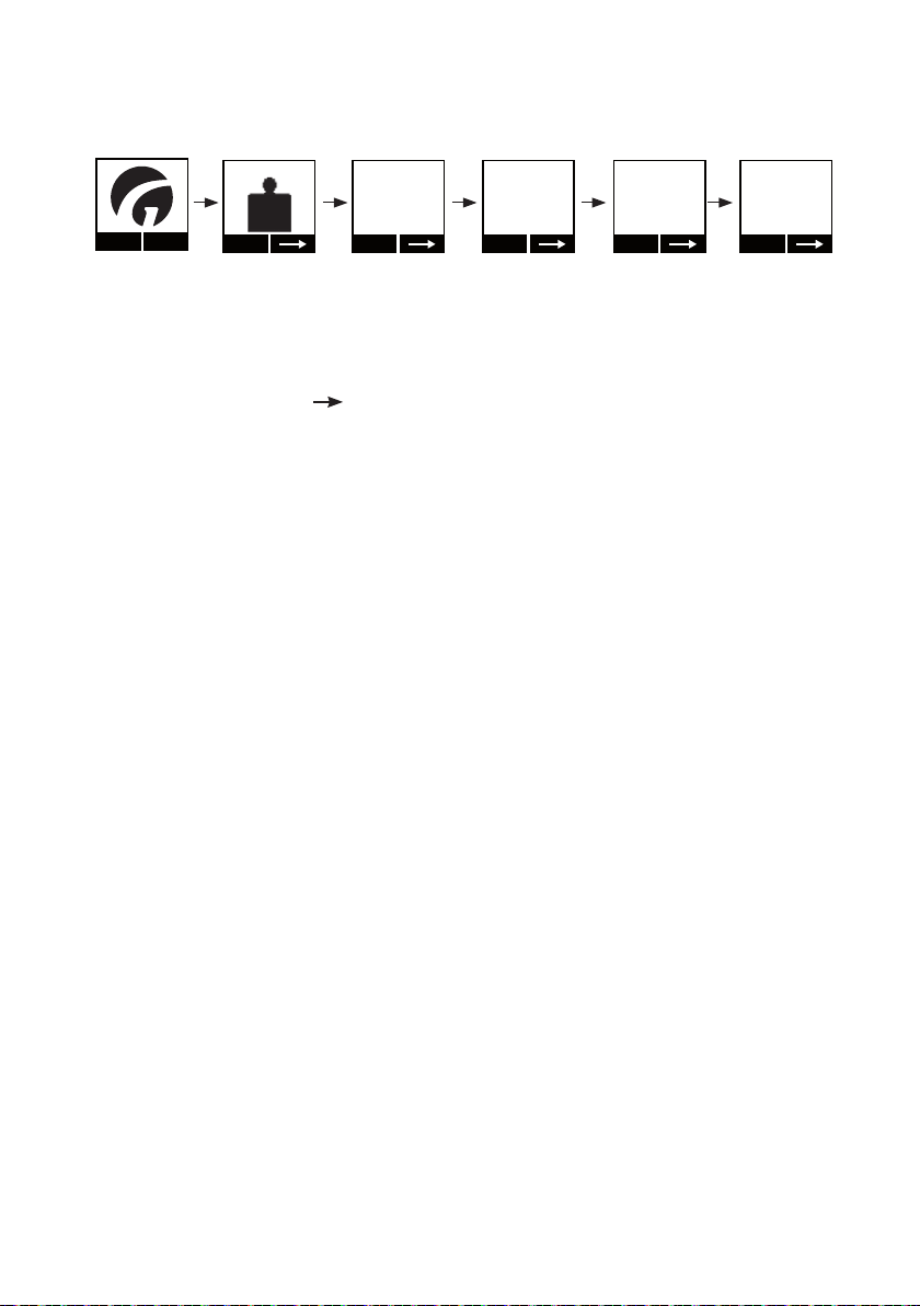
Screen utilised when using the Class III scale
Scale
W1
Scale W1
Scale W1
Scale W1
Scale W2
Start-up logo:
Press ”menu” to select the function
Menu
Menu icon for ”scale”.
Press the left navigation button ”Start” to enter the menu.
III
Start
Scale
- - -
Tar e
Scale
0.0 kg
►0◄
Tar e
87.3 kg
Tar e
125.7
Tar e
65.2 kg
Tar e
215.8 kg
Tar e
Exit
Exit
NET
Exit
Exit
Scale (in the scale menu): the scale starts up and resetting occurs
automatically:
• Weight indication replaced by ashing lines
• Wait up to 10 sec before weight is shown
Weight (in scale menu): symbol for 0 is shown and means:
• The scale has been reset but has not yet been tared
• Weighing is being performed in weighing area 1 (W1)
Scale (in the scale menu): normal weighing.
• Here the weight is shown in weighing area 1 (W1)
• The sling is at rest and the weighing is therefore valid (as indicated
by the ”kg” sign)
Weight (in scale menu): normal weighing
• The scale is in weighing area 1 (W1)
• The sling is not at rest, and the scale is therefore not ready for
weighing (”kg” sign is not shown)
Weight (in scale menu):
• Net weight (NET) is shown as a result of the scale being tared
• Weighing range 1 (W1)
• The sling is at rest and the scale is ready for weighing (kg)
Weight (in scale menu):
• Net weight (”NET” is turned off): the weight has not been tared
• Weighing range 2 (W2)
• The sling is at rest and the scale is ready for weighing (kg)
28
© Guldmann GB/US- 12/2018 • # 550383_9.00

Scale Info 1-2
Version (information screen 1 of 2 in scale menu):
Scale W2
Scale W1
Version
01.00
Next
Scale Info 2-2
Changes
001
Next Exit
• The number before the decimal counts the software versions and
• The number after the decimal counts minor software modications
Changes (information screen 2 of 2 in scale menu): change counter
• Counts changes in software parameters such as calibration and
Error notications
- - -
Exit
The scale is overloaded.
Please follow the scale’s prescribed load (see identication label on
the hoist).
- - -
Reset Exit
Scale
004
The scale is below the minimum possible reading value
(in other words, the load weighed is under 2 kg).
Select ”Reset” and start over with setting the scale.
An error has occured in the scale. The display shows an error code
(see table below)
larger modications
and bug xes
values for G factor
© Guldmann GB/US-12/2018 • # 550383_9.00
ExitReset
29

2.09 Calibration/verication of Classe III Scale
In order to maintain the medical approval the digital scale must be calibrated/
veried according to national regulatory requirements at an accredited testing
institute.
Software version and change counter are veried on the hand control’s display.
In daily use it can be veried that the system is approved for medical use by
a Notied Body by conrming that ”Software version counter” reads 1 and the
”Event counter” on the display corresponds with the counter values on the
verication label.
Both values are 1 from the factory and until the rst re-verications.
Scale Info 2-2
Changes
001
Next Exit
Menu
Scale Info 1-2
Version
01.00
Next
1. Press any key on the hand control to activate the display.
2. Select “Menu” using the function key located immediately below the display.
3. Next, select until the ”Version” menu appears in the display.
Version (information screen 1 of 2 in scale menu):
• The number before the decimal counts the software versions and larger
modications;
• The number after the decimal counts minor software modications and bug
xes
4. Select ”next” to read ”Changes”.
Changes (information screen 2 of 2 in scale menu): change counter
• Counts changes in software parameters such as calibration and values for
G factor
5. Press EXIT to get back to the main menu.
30
© Guldmann GB/US- 12/2018 • # 550383_9.00
2.10 CLM module (GH3 with statistical function for management use)
The GH3 with CLM module (option) includes a management tool that saves
important information on the use of the lifting module and which can be used
to evaluate the system’s efciency and utilisation, as well as to optimise
its use and hoist name/location.
The following data can be shown on the hand control’s display: number of
lifts, number of heavy lifts, number of lifts in last week, average number of
lifts per week.
As an additional option, by connecting a PDA/Net Book to the hand control it
is possible to gain access to a number of other saved data, e.g. the number
of lifts since the last strap change, number of critically low battery readings,
number of weighings, total lifting time, etc.
This information can be downloaded and used for further analysis.
(PDA/Net Book readouts requires a PDA/Net Book with Guldmann Service
and Information consol).
Number of lifts, total A lift is registered automatically when the following
Number of heavy lifts, total A heavy lift is registered automatically when the
Number of lifts, last week The total number of lifts performed within the last
Average number of lifts per
week
events are registered simultaneously
• Hand control is activated
(Direction UP) for more than 2 seconds
• The load on the lifting strap is registered as
being within the range:
15 kg – Recommended load kg
(33 lbs – Recommended load lbs)
Total includes the number of lifts performed after
the lifting module was first taken into use.
following events are registered simultaneously
• Hand control is activated (Direction UP) for
more than 2 seconds
• The load on the lifting strap is registered as
being within the range:
150 kg – Recommended load kg
(330 lbs – Recommended load lbs)
Total includes the number of heavy lifts performed
after the lifting module was first taken into use.
seven calendar days
Average number of lifts per week (performed after
the lifting module was first taken into use)
The data for “Number of lifts, last week” and “Average number of lifts
per week” can, if necessary, be reset using a PDA/Net Book.
© Guldmann GB/US-12/2018 • # 550383_9.00
31

Operation
Menu Start
Scale
KG
CLM
Show
CLM 1-5
Lifetime
total lifts
987
1-5
Number
of lifts,
total
ExitNext
CLM 2-5
Lifetime
heavy lifts
232
ExitNext
2-5
Number
of heavy lifts,
total
CLM 3-5
Last week
total lifts
60
ExitNext
3-5
Number
of lifts last week
CLM 4-5
Lifts per
week avg
72
4-5
Average
numbers
of lifts per
CLM 5-5
Hoist ID
Hoist #1
ExitNext
5-5
Hoist ID
week
1. Press any key on the GH3 hand control to activate the hoist.
When the lifting module is activated, the display on the hand control
is switched on and the Guldmann logo “G” appears.
2. Select “Menu” using the function key located below the display.
3. Then select until the “CLM” menu appears in the display.
4. Then select “Show”.
5. Then select “Next” until the required information appears in the display.
6. Select “Exit” to return to the main menu.
Note:
The display on the hand control will automatically revert to the screensaver
after approx. 8 min.
ExitNext
Accessories for the CLM module, GH3
The CLM module includes an extended management menu which can be
operated via a PDA/Net Book (with Guldmann Service and Information consol
installed).
The PDA/Net Book is connected to the hand control via a mini USB plug
located in the base of the hand control (see section 2.04).
Contact supplier or the Guldmann Service Team for further information about
CLM accessories.
32
© Guldmann GB/US- 12/2018 • # 550383_9.00

2.11 Service module (GH3 with service module)
The GH3 with Service module (option) saves all of the information
about time and indication of next safety/service inspection.
The GH3 with Service module species the date of the next
safety/service inspection.
Operation
Scale
KG
Menu Show
Start
CLM
Next service
2008.04.22
1. Press any key on the hand control to activate the hoist. When the lifting
module is activated, a display on the hand control is switched on and the
Guldmann logo “G” appears.
2. Select “Menu” using the function key located immediately below the display.
3. Then select until the “Next service:” menu item appears in the
display.
4. Read off the date of the next safety/service inspection (Year, Month, Date).
© Guldmann GB/US-12/2018 • # 550383_9.00
33

Pop-Up’s for Service module (supplementary module)
There are two different Pop-Up’s (brief messages on the display) on the
GH3 with Service module. These pop-up’s notify the user of upcoming
and exceeded dates for service inspections.
Both Pop-Up’s appear immediately after the hand control has been
switched on.
Pop-Up’s before and after “Service Date”
Next service
Next service
Service done
2008.04.22
2009.04.22
1. Pop-Up, 60 days
The next service inspection must be undertaken within 60 days.
Select “OK” to return to the main menu
(returns automatically after approx. 5 seconds).
Next service
2008.04.22
If service is not performed
Service date
exceeded
call service
Exit
2. Pop-Up, Service date exceeded
The date of the service inspection has been exceeded, contact the
Guldmann Service Team.
Select “Exit” to return to the main menu (returns automatically after
approx. 5 seconds).
Attention!
If the service date is exceeded by more than 60 days, the hoist makes an
acoustic signal, at any button activation.
The Acoustic signal can be disabled by the “Guldmann Service and Information Consol” software.
Note:
The display on the hand control will automatically revert to the screensaver
after approx. 8 minutes.
34
© Guldmann GB/US- 12/2018 • # 550383_9.00

2.12 Safety functions
The emergency stop and emergency lower should only be used in the event
of hoist failure or fault. The fault must be identied and rectied by a suitably
qualied technician before the hoist can be taken back into use. The Emergency stop should not be reset unless by a suitably qualied technician.
Under no circumstances should the user attempt to reset and continue to use
the hoist where the emergency stop has been activated due to fault or failure.
The hoist issue should be referred for service and rectication by a suitably
qualied technician.
Emergency stop and lowering strap
The red strap has the following functions:
• One pull: Emergency stop is activated.
• Constant pull (2 steps): Emergency lowering is activated. It will work with
following load:
GH3 Twin up to 500 kg/1100 lbs from approx. load 160 kg/350 lbs
Emergency stop
If the GH3 does not stop/react to the hand control when the GH3 is in
use, pull the red strap and the lifting/lowering functions (except emergency
lowering) are deactivated. When the emergency stop is activated, the hoist
will not function. The green lamp is switched off.
Reset emergency stop
Reset the emergency stop by pressing the
yellow button on the bottom of the hoist.
The yellow button that appears when the
emergency stop is pulled, must be pressed
manually before the GH3 is ready for use.
© Guldmann GB/US-12/2018 • # 550383_9.00
35

Emergency lowering function, electric
If the GH3 fails, the electrical emergency lowering function is used to lower
the user safely. The emergency lowering function is operated by a constant
pull on the red strap that is used for the emergency stop.
When releasing the red strap, the emergency lowering function will be
replaced by the emergency stop.
Emergency lowering function, mechanical
If the electrical emergency lowering function in the GH3 fails, the emergency
lowering can be done mechanically. This must be done on the leader hoist
and follower hoist.
1. Remove the side covers.
Release the side covers from the top of
the hoist by means of a gentle push on
the xing points on each side. The covers
are tipped free of the hoist and can be
removed.
2. Then release the hoist’s motor by turning
the handle bearing the words
“EMERGENCY DOWN”. This handle is
located immediately behind the side cover
and must be turned clockwise.
36
© Guldmann GB/US- 12/2018 • # 550383_9.00

3. When the brake(s) has/have been
released, the user will be lowered slowly.
If the total weight of the user and the lifting
accessories is low (e.g. less than 100 kg
(220 lbs), it may be necessary to help the
user down by turning the large belt wheel
located on the opposite side of the handle
and in the direction of arrow marked on
the belt wheel.
Note:
In case of a critical mechanical failure, the hoist contains a mechanical
protective system that stops the strap reel.
Warning!
After the mechanical protective system has been activated in the GH3, the
hoist MUST be serviced by a qualied technician or by the Guldmann Service
Team.
2.13 Charging/connection
The GH3 is automatically charged along the entire length of the straight rails.
This guarantees the hoist functionality and maintains the batteries to ensure
a long lifetime.
The indicator lamp on the bottom of the hoist turns yellow if the charge status
becomes low or if there is a complete interruption to the charging function.
The GH3 then has a limited number of lifts available at a time and must be
re-charged.
The transformer must be connected and switched on before charging can
take place. A green indicator lamp on the transformer indicates that it is
connected and switched on.
2.14 Accessories
Guldmann – ABC slings and lifting hangers
Obtain a brochure from your distributor, manufacturer or at
www.guldmann.com
Extension strap 550459
The extension strap is used where the distance between the lower part of the
rails and the oor exceeds 3.5 m (11' 7"). The extension strap is available as
an accessory.
Cross Hanger 550800 with Connecting Bar 550544
Positioning the sling:
Cross Hanger is positioned with the lifting arms marked “FRONT” farthest
away from the user. The rear straps of the sling are to be positioned on the
two hooks closet to the user and the leg straps on the hooks farthest away
© Guldmann GB/US-12/2018 • # 550383_9.00
from the user.
37

Lifting sling with divided leg straps:
Place the sling with the wide side facing the user. Hook the back straps on
the hoist onto the hooks closest to the user and the leg straps to the hooks
farthest away from the user.
Horizontal lifter, foldable 28444
The horizontal lifter is a lifting device which is used together with a hoist
and rail systems to move people in a horizontal position. It can be stored
completely or partially folded in order to minimise space requirements, or it
can hang ready to use in the hoist.
The horizontal lifter may be used only for horizontal relocation of people lying
on a level, horizontal surface. The person must be lying on a Guldmann sling
or on another suitable sling. A level surface can be, for example, a bed, a
stretcher or the oor.
Batteries
NiMH Battery 24V/2000mAh, Guldmann type number 550574.
Transformer
Transformer, Class 1, Guldmann item number 550391
3.00 Environmental conditions
Operation
The products operational environment:
– Operation temperatures between 10°C and +35°C / 50°F and 95°F
– A relative air humidity of between 30% and 70%
– An air pressure of between 700 hPa and 1060 hPa
Information is illustrated by symbols on packaging including:
– Fragile
– This side up
Beside temperature, the same environmental conditions apply for
transportation and storage.
– Transport and storage temperatures between -10°C and +40°C / 14°F and
104°F
The equipment is not designed to be used at altitudes higher than 2000m.
above sea level.
38
© Guldmann GB/US- 12/2018 • # 550383_9.00

Key to symbols on the packaging:
40ºC
104ºF
-10ºC
14ºF
30%
Transport and storage
Guldmann recommends that the products are always transported and stored
in the original packaging.
4.00 Maintenance and storage
4.01 Cleaning and disinfection
We recommend that the products and the parts patients and caregivers can
come in contact with, are cleaned with a damp cloth using warm water and a
mild soap solution.
When disinfection is needed, use disinfectant wipes with up to a 85% solution of
isopropyl, or a damp cloth using warm water and a disinfectant cleaner, e.g. an
chlorine dissolving up to 1500 ppm.
If other chemicals and/or liquids with higher resolution should be used to clean
or disinfect these products, please contact Guldmann providing the item´s safety
sheet chemical composition for consideration.
Caution: Take great care to ensure that no liquids get inside the lift. The lift is
not waterproof. Failure to protect the lift from liquids may result in damage to
the lift and/or may cause personal injury.
70%
106 kPa
70 kPa
4.02 Storage
See 3.00
For long-therm storage, disconnect the battery plugs and the plug at the
charging PC from the battery.
4.03 How to prevent/avoid corrosion?
When the GH3 is mainly used in an corrosive environment, e.g. swimming
pool, the hoist must be ordered with a special corrosion-preventive surface
treatment.
© Guldmann GB/US-12/2018 • # 550383_9.00
39

4.04 The owner’s daily maintenance duty
Check the lifting sling for wear and damage before use.
Do not use the lifting sling if it is damaged or defective.
Do not use the GH3 if the lifting strap is damaged or defective.
Contact your supplier and order a new lifting sling or a replacement of the
lifting strap. Replacement of the lifting strap must only be performed by
the Guldmann Service Team or by a qualied technician in accordance with
Guldmann’s instructions.
4.05 Disposal of the GH3 including batteries
Local and national regulations on environmentally correct recycling must be
observed.
Batteries (type NiMH) must always be delivered to an approved recycling
point.
5.00 Service and lifetime
5.01 Lifetime
The products have an expected lifetime of 15 years, on the condition of
correct use and correct service inspections, see section 5.02.
Replacement of components
Replacement of batteries, PCBs, load cells and lifting straps must be performed by a qualied service technician or the Guldmann Service Team. Class
III scales must be veried by a Notied Body after servicing.
Any modication to Class III scales, to the metric system and the legal software shall free the supplier of any responsibility for damages that may occur
as a result of errors in weighing patients.
No part of the equipment shall be serviced when in use with a patient.
5.02 Safety/service inspections
In accordance with international standard EN/ISO 10535 “Hoist for the
transfer of disabled persons – Requirements and test methods” an inspection
should be performed on the hoist at least once a year.
Guldmann recommends that regular safety/service inspection is performed at
least once a year with regard to the pattern of usage.
Inspection of the GH3 must be performed by a qualied service technician or
the Guldmann Service Team.
In connection with the purchase of the GH3, Guldmann may offer a service
agreement for this inspection.
NB!
The GH3 with service module may only be serviced by the
Guldmann Service Team or by a qualied service technician with access
to the PDA/Net Book with Guldmann Service and Information consol.
40
© Guldmann GB/US- 12/2018 • # 550383_9.00

During the safety/service inspection a report must be prepared on what was
checked and replaced. Parts that are worn or defective must be replaced with
new parts from Guldmann. Spare parts drawings and documentation can be
obtained from the manufacturer or supplier.
Documentation/checklist regarding safety/service inspection can be obtained
from the manufacturer or supplier.
Re-verifying Class III scales
To maintain the medical approval of a Class III scale, the digital scale must
be re-veried/calibrated in accordance with local regulatory requirements and
by a Notied Body.
5.03 Troubleshooting
The GH3 does not respond to the hand control’s keys
1. Check the emergency stop is not activated
2. Check the hoist has power supply
3. Check the transformer is switched on and connected to the rail system
4. Contact the Guldmann Service Team
6.00 Classication
Type B in accordance with UL/EN 60601-1
CE marking
Read the manual before use
Must not be disposed of as standard household waste, must be
recycled.
Class I equipment: Permanent installation with protective ground
Class II equipment: Non-permanent installation without protective ground
The equipment is not suitable for use in the presence of ammable mixtures.
Degree of protection against harmfull ingress of liquids (water)
Hoist IP20
Hand control IP44
Remote control IP20
© Guldmann GB/US-12/2018 • # 550383_9.00
Transformer IP20
41

ECTYNO 0200-NAWI-03847
Event Counter: 1
Guldmann Scale Class
e = kg Min kg Max kg
W1 xxx xxx xxx
W2 xxx xxx xxx
M xx
0200
Examples of serial number label
Part no. xxxxxx
Edition xx x
Prod. date yyyy-mm-dd
Serial no. x xxx x
max
xxx kg/xxx lbs
V. Guldmann A/S
www.guldmann.com
Barcode 128C
Part no. xxxxxx
Edition xxx
Date xxxx-xx-xx
IP44
max xxx kg / xxx lbs
xxxxxx
xxxxx
GH3+ xxx xxx xxxx
V. Guldmann A/S
Graham Bells Vej 21-23A
8200 Aarhus N, Denmark
Made in Denmark
yyyy-mm-dd
33V AC, 2.5A, IP20
Duty cycle 2 min ON/18 min OFF
GS1-128
V. Guldmann A/S
Graham Bells Vej 21-23A
8200 Aarhus N Denmark
Made in China
Type DK-13991
Input 100 - 115V AC 50-60 Hz, 1A
Input 230V AC 50-60 Hz, 0,5A
Input 220V AC 60 Hz, 0,5A
Output 33V AC 2,5A
IP20
year/week
Batch No.
Lifting module
Transformer Class 1
Lifting hanger Hand control
Type approval label,
lifting module with Class III scale
42
© Guldmann GB/US- 12/2018 • # 550383_9.00

7.00 Certicates
EN/ISO10535 HMI No. 08.49A, 09.14A, 09.15A
8.00 Technical specications
GH3 Lifting modules, congurations
Guldmann
hoist type
GH3 (x) xxx x x x (x) x x x x
GH3 200 1 1 0 - 1 - 2 Hand
Product
Load inkgNumber
line
250 1 1 0 - 1 - 2
+ 250 1 1 0 - 1 - 2 None:
275 1 1 0 - 1 - 2
300 1 2 0 - 2
350 1 2 0 - 2
375 1 2 0 - 2
400 1 2 0
Twin 250 2 2 0
500 2 2 0
of lifting
straps
Number
of lifting
motors
Number of
horizontal
drive
motors
WIFI
module
empty
WIFI: 1
Scale
module
None: 0
Scale: 1
Class III
Scale: 2
CLM
module
None: 0
CLM: 1
Service
module
None: 0
Service: 1
User
interface
control: 0
IR: 1
GH3 X Y Z Z Z Q Q Q Q Q
Example: GH3+ 350 122 1000
GH3
© Guldmann GB/US-12/2018 • # 550383_9.00
+ 350 1 2 2 1 0 0 0
Hand control
w/o Service module
w/o CLM module
Scale module
2 horizontal drive motors
2 lifting motors
1 lifting strap
Safe Working Load SWL: 350 kg
+
Ceiling hoist, type GH3
43

Functions
Lifting capacity,
SWL ..............................250 kg (550 lbs), 500 kg (1100 lbs)
Operation .........................................Hand control / IR
Sound level .............................................52 dB (A)
GH3 Twin
Lifting speed
85 kg (187 lbs) load 60 mm/sec (2.4 inch/sec)
150 kg (330 lbs) load 60 mm/sec (2.4 inch/sec)
Max capacity load, SWL 55 mm/sec (2.2 inch/sec)
Max 5 kg (11 lbs) load 60/100 mm/sec
Max 11 lbs load 2.4/3.9 inch/sec
Weight and materials
SWL .............................. 250 kg (550 lbs), 500 kg (1100 lbs)
Own weight, SWL 250 kg (550 lbs), 500 kg (1100 lbs) .....19.2 kg (42.3 lbs)
Covers ........Impact-resistant UL 94 V-0 ame retardant recyclable plastic
Digital Scale Specications (Non medical). Optional for GH3 Twin
Capacity ................................................ 0 – SWL
Accuracy .....................................+/- 0.1 % at max load
Repeatability ........................ < 0.1 kg at 0-250 kg (0 – 550 lbs)
................................ < 0.2 kg at 0-500 kg (0 – 1100 lbs)
Minimum weight ....................................... 5 kg (11 lbs)
Display type ....................................LCD in Hand Control
Class III Scale Specications. Supplementary module for GH3 Twin
Capacity .................................................0 - SWL
Accuracy class .................................................III
Weighing range .....................Single-interval or multi-range (dual)
Maximum number of Verication Scale Intervals. . . . . . . . . . . . . . . . . . . . 2000
Maximum capacity (Max) .............................200 kg to 700 kg
Verication Scale Interval(e1) ............................... ≥ 0.1 kg
Minimum capacity (Min) ........................................20 e
Maximum tare effect ........................................≤ -Max
Operational temperature, scale ........................ +10°C - +40°C
44
© Guldmann GB/US- 12/2018 • # 550383_9.00

Dimensions
A ............................................1800 mm (70.9 inch)
B .............................................700 mm (27.6 inch)
C .............................................156 mm (6.1 inch)
D .............................................184 mm (7.2 inch)
E, min ..........................................194 mm (7.6 inch)
F, min .........................................630 mm (24.8 inch)
F, max .......................................3130 mm (98.4 inch)
G .............................................473 mm (18,6 inch)
I ..............................................620 mm (24.4 inch)
J .............................................790 mm (28.3 inch)
K .............................................490 mm (19.3 inch)
L .............................................473 mm (18.6 inch)
Depth of hoist ....................................205 mm (8.1 inch)
Safety
Emergency stop .............................................. Ye s
Emergency lowering device ............... Yes, mechanical and electrical
Control of lifting strap .........................................Yes
Cut-off angle ......................45° along the rail 10° across the rail
B
D
C
© Guldmann GB/US-12/2018 • # 550383_9.00
FE
L
K
A
I
G
J
45

Electronics
On/off ............................Automatic when used. Soft start/stop
Overload protection ...................................... Automatic
Low Battery protection .................................... Automatic
Power supply ........................................33V AC, 2.5 A
Supply voltage, transformer ..................100-115/230V AC, 50-60 Hz
Battery ................................................24V NiMH
SWL: 250 kg (550 lbs), 500 kg (1100 lbs) ....................2 x 2.00 Ah
Continuous operation with short time loading with:
3 hours without recharging .........10/90% (2 min operation/18 min pause)
Max number of lifts in series with:
85 kg (187 lbs) ...............................55/1000 mm (39.4 inch)
SWL: 250 kg (550 lbs), 500 kg (1100 lbs) ..........21/1000 mm (39.4 inch)
Max charging time at 25ºC:
SWL: 250 kg (550 lbs), 500 kg (1100 lbs) ....................... 4 hours
Operating temperature ..........................10ºC-35ºC (50ºF-95ºF)
Degree of protection against harmful ingress of liquids (water)
Hoist ......................................................IP 20
Hand control. . . . . . . . . . . . . . . . . . . . . . . . . . . . . . . . . . . . . . . . . . . . . . . . IP 44
Remote control. . . . . . . . . . . . . . . . . . . . . . . . . . . . . . . . . . . . . . . . . . . . . . IP 20
Transformer ................................................IP 20
9.00 EC-Declaration of conformity
The products are manufactured in compliance with the Council Directive
93/42/EEC of 14 June 1993 – with amendments, as medical device class 1.
Class III Scale is complying with the directive 2014/31/EU of the European
Parliament and of the Council of 26 February 2014 on the harmonisation of
the laws of the Member States relating to the making available on the market
of non-automatic weighing instruments.
46
© Guldmann GB/US- 12/2018 • # 550383_9.00

10.00 Type approval certicate
The Class III scale has the EU type examination certicate number 0200-
NAWI-03847.
EU Type Examination Certificate
No. 0200-NAWI-03847
GH3+
NON-AUTOMATIC WEIGHING INSTRUMENT
Issued by FORCE Certification
EU - Notified Body No. 0200
In accordance with the requirements in Directive 2014/31/EU of the European Parliament and
Council.
Issued to V. Guldmann A/S
In respect of Non-automatic weighing instrument designated GH3+ with variants of modules of
Accuracy class III, single-interval or multi range (dual)
Maximum capacity, Max: From 200 kg to 700 kg
Ve rification scale interval: e
Maximum number of verification scale intervals: n
Variants of models are set out in the annex.
The conformity with the essential requirements in annex 1 of the Directive is met by the application of
EN 45501:2015 and of OIML R76:2006.
The principal characteristics and approval conditions are set out in the descriptive
annex to this certificate.
The annex comprises 8 pages.
Issued on 2018-07-05
Valid until 2028-07-05 Signatory: J. Hovgård
FORCE Certification references:
Task no.: 118-23277 and ID no.: 0200-NAWI-03847
Graham Bells Vej 21-23A,
8200 Aarhus N
DENMARK
load receptors and load cells.
= Maxi/ ni
i
= 2000.
© Guldmann GB/US-12/2018 • # 550383_9.00
47

11.00 Environmental policy statement - V. Guldmann A/S
Guldmann is continuously working towards ensuring that the company’s
impact on the environment, locally and globally, is reduced to a minimum.
It is Guldmann’s goal to:
• Comply with the current environmental legislation (e.g. WEEE and REACH
directives)
• Ensure that we, at the widest possible range, use RoHS compliant materials
and components
• Ensure that our products do not have an unnecessary negative impact on the
environment regarding use, recirculation or disposal
• Ensure that our products contribute to a positive working environment in the
places they are utilised
Inspections are made annually by the Department for Nature and Environment from the Municipality of Aarhus using the Danish Environmental Protection Act, section 42 as a reference.
12.00 EMC Information
Tabel 1
Guidance and manufacturer’s declaration – electromagnetic emissions
The GH3 is intended for use in the electromagnetic environment specified below.
The customer or the user of the GH3 should assure that it is used in such an environment.
Emissions test Compliance Electromagnetic environment – guidance
RF emissions
CISPR 11
RF emissions
CISPR 11
Harmonic emissions
IEC 61000-3-2
Voltage fluctuations/
flicker emissions
IEC 61000-3-3
Group 1 The GH3 uses RF energy only for its internal function. Therefore, its
Class B
Class A The GH3 is suitable for use in all establishments, including do-
Complies
RF emissions are very low and are not likely to cause any interference in nearby electronic equipment.
mestic establishments and those directly connected to the public
low-voltage power supply network that supplies buildings used for
domestic purposes.
48
© Guldmann GB/US- 12/2018 • # 550383_9.00
Tabel 2
Guidance and manufacturer’s declaration – electromagnetic immunity
The GH3 is intended for use in the electromagnetic environment specified below.
The customer or the user of the GH3 should assure that it is used in such an environment.
IMMUNITY test IEC 60601
test level
Electrostatic
discharge (ESD)
±6 kV contact
±8 kV air
IEC 61000-4-2
±2 kV for power
supply lines
±1 kV for input/output
lines
Surge
IEC 61000-4-5
Voltage dips,
short interruptions and voltage
variations on
power supply
input lines IEC
61000-4-11
±1 kV line(s) to line(s)
±2 kV line(s) to earth
<5 % U
T
(>95 % dip in UT)
for 0,5 cycle
40 % U
T
(60 % dip in UT)
for 5 cycles
70 % U
T
(30 % dip in UT)
for 25 cycles
70 % U
T
(30 % dip in UT)
for 25 cycles
Power frequency
3 A/m 3 A/m The power frequency magnetic
(50/60 Hz)
magnetic field
IEC 61000-4-8
NOTE U
is the a.c. mains voltage prior to application of the test level.
T
Compliance level Electromagnetic environment
– guidance
±6 kV contact
±8 kV air
Floors should be wood, concrete
or ceramic tile. If floors are covered
with synthetic material, the relative
humidity should be at least 30 %.
±2 kV for power
supply lines
±1 kV for input/output
Mains power quality should be that
of a typical commercial or hospital
environment.
lines
±1 kV differential mode
±2 kV common mode
Mains power quality should be that
of a typical commercial or hospital
environment.
<5 % U
T
(>95 % dip in UT)
for 0,5 cycle
40 % U
T
(60 % dip in UT)
for 5 cycles
70 % U
T
(30 % dip in UT)
Mains power quality should be that
of a typical commercial or hospital
environment. If the user of the
GH3 requires continued operation
during power mains interruptions,
it is recommended that the GH3
be powered from an uninterruptible
power supply or a battery.
for 25 cycles
<5 % U
T
(>95 % dip in UT)
for 5 s
field should be measured in the
intended installation location to
assure that it is sufficiently low.
© Guldmann GB/US-12/2018 • # 550383_9.00
49

Tabel 4
Guidance and manufacturer’s declaration – electromagnetic immunity
The GH3 is intended for use in the electromagnetic environment specified below.
The customer or the user of the GH3 should assure that it is used in such an environment.
IMMUNITY test IEC 60601 TEST
LEVEL
Conducted RF
IEC 61000-4-6
Radiated RF
IEC 61000-4-3
3 Vrms
150 kHz to 80 MHz
3 V/m
80 MHz to 2,5 GHz
Compliance
level
3 Vrms
3 V/m
Electromagnetic environment
– guidance
Portable and mobile RF communications equipment should be used no closer to any part of
the GH3, including cables, than the recommended separation distance calculated from
the equation applicable to the frequency of the
transmitter.
Recommended separation
distance
d=1,2√Pd=1,2√P 80 MHz to 800 MHz
d=2,3√P 800 MHz to 2,5 GHz
Where P is the maximum output power rating
of the transmitter in watts (W) according to the
transmitter manufacturer and d is the recommended separation distance in meters (m).
Field strengths from fixed RF transmitters, as
determined by an electromagnetic site survey
should be less than the compliance level in each
frequency range
b)
Interference may occur in the vicinity of equipment marked with the following symbol:
a)
NOTE 1 At 80 MHz and 800 MHz, the higher frequency range applies.
NOTE 2 These guidelines may not apply in all situations. Electromagnetic propagation is affected by
absorption and reflection from structures, objects and people.
a)
Field strengths from fixed transmitters, such as base stations for radio (cellular/cordless) telephones and
land mobile radios, amateur radio, AM and FM radio broadcast and TV broadcast cannot be predicted
theoretically with accuracy. To assess the electromagnetic environment due to fixed RF transmitters, an electromagnetic site survey should be considered. If the measured field strength in the location in which the GH3
is used exceeds the applicable RF compliance level above, the GH3 should be observed to verify normal
operation. If abnormal performance is observed, additional measures may be necessary, such as re-orienting
or relocating the GH3.
b)
Over the frequency range 150 kHz to 80 MHz, field strengths should be less than 3 V/m.
50
© Guldmann GB/US- 12/2018 • # 550383_9.00

Tabel 6
Recommended separation distances between
portable and mobile RF communications equipment and the GH3
The GH3 is intended for use in an electromagnetic environment in which radiated RF disturbances are controlled. The customer or the user of the GH3 can help prevent electromagnetic interference by maintaining a
minimum distance between portable and mobile RF communications equipment (transmitters) and the GH3
as recommended below, according to the maximum output power of the communications equipment.
Rated
maximum
output power
of transmitter
W
0,01 0,12 0,12 0,23
0,1 0,38 0,38 0,73
1 1,2 1,2 2,3
10 3,8 3,8 7,3
100 12 12 23
For transmitters rated at a maximum output power not listed above, the recommended separation distance d
in meters (m) can be estimated using the equation applicable to the frequency of the transmitter, where P is
the maximum output power rating of the transmitter in watts (W) according to the transmitter manufacturer.
NOTE 1 At 80 MHz and 800 MHz, the separation distance for the higher frequency range applies.
NOTE 2 These guidelines may not apply in all situations. Electromagnetic propagation is affected by absorption and reflection from structures, objects and people.
Separation distance according to frequency of transmitter
m
150 kHz to 80 MHz
d=1,2√P
80 MHz to 800 MHz
d=1,2√P
800 MHz to 2,5 GHz
d=2,3√P
© Guldmann GB/US-12/2018 • # 550383_9.00
51

USA and countries outside the EU
A. Users guide
Before using the product, read the entire operation manual
including warranty.
B. WARRANTY
Guldmann warrants its equipment is free from material defects under normal
use, and will perform substantially in accordance with the specications set
forth in documentation provided with the equipment.
This express warranty shall be in effect for one year from the date of original
purchase and installation (the “Warranty Period”). If a valid claim is made
during the Warranty Period for malfunction or equipment defect, Guldmann will
repair or replace the equipment at no additional cost to you. Guldmann retains
sole discretion as to whether the equipment will be repaired or replaced.
This warranty shall be null and void if the equipment is operated and maintained in any manner inconsistent with its intended use or the instructions
provided with the product. Further, in order for the warranty to remain in effect
for the full Warranty Period, all service to the equipment must be provided
by a Guldmann designated technician. Any parts or components repaired or
replaced by a Guldmann designated technician will be guaranteed for the
remainder of the Warranty Period.
The warranty does not cover any part of the equipment which has been subject to damage or abuse by the user or others. The warranty does not cover
any part of the equipment which has been altered or changed in any way by
the user or others. Guldmann does not warrant that the lifting device functions
will meet your requirements, be uninterrupted or error free.
The warranty set forth is in lieu of all other express and implied warranties,
whether oral, written or implied, and the remedies set forth above are your
sole and exclusive remedies. Only an authorized ofcer of Guldmann may
make modications to this warranty, or additional warranties binding on Guldmann. Accordingly, additional statements such as advertising or presentations, whether oral or written, do not constitute warranties by Guldmann.
Service or Repair
Contact Guldmann Repair for an authorization to return any defective item
during the Warranty Period. You will be provided with a return authorization
number and address for returning the item for warranty service or replacement. Do not return items to Guldmann under warranty without receiving a
Return Authorization Number.
If mailing the item, pack it carefully in a sturdy carton to prevent damage.
Include your Return Authorization Number, a brief description of the problem
and your return address and phone number. Guldmann does not assume the
risk of loss or damage while in transit, so it is recommended you insure the
package.
52
© Guldmann GB/US- 12/2018 • # 550383_9.00

© Guldmann GB/US-12/2018 • # 550383_9.00
53

54
© Guldmann GB/US- 12/2018 • # 550383_9.00

© Guldmann GB/US-12/2018 • # 550383_9.00
55

© Guldmann GB/US-12/2018 • # 550383_9.00
V. Guldmann A/S
Corporate Ofce:
Tel. +45 8741 3100
Fax +45 8741 3131
info@guldmann.com
www.guldmann.com
Guldmann Inc.
Tel. 800 664 8834
Tel. 813 880 0619
Fax 813 880 9558
info@guldmann.net
www.guldmann.net
56
 Loading...