

Guldmann GH1, GH1 Q User Manual
GB/US ........ GH1/GH1 Q Ceiling Hoist
User manual – vers. 14.00
1

2
© Guldmann GB/US-1706/12/2016 • # 550865_14

GH1/GH1 Q Ceiling Hoist
1.00 .........Purpose and intended use ......................................4
1.01 .........Manufacturer ..................................................4
1.02 .........Intended use ..................................................4
1.03 .........Purpose ......................................................4
1.04 .........Important/Precautions ...........................................4
1.05 .........Load limits on GH1 system .......................................5
1.06 .........Unpacking and Preparation .......................................5
1.07 .........Installing a new GH1 hoist in an existing rail system ...................6
1.08 .........Installing / deinstalling GH1 Q in the rail .............................7
1.09 .........Power supply ..................................................8
1.10 .........Installation of the lifting hanger before use ...........................9
1.11 .........Lifting sling ...................................................10
1.12 .........Swing kit. . . . . . . . . . . . . . . . . . . . . . . . . . . . . . . . . . . . . . . . . . . . . . . . . . . . . 13
1.13 .........Using swing kit in doorway ......................................14
1.14 .........Exchange of side cover .........................................15
2.00 .........Description of functions .......................................15
2.01 .........Pictograms ...................................................16
2.02 .........Indicator lamps and audio signals .................................16
2.03 .........Operation ....................................................16
2.04 .........Safety functions ...............................................18
2.05 .........Accessories ..................................................19
3.00 .........Transport and storage .........................................21
4.00 .........Maintenance and storage ......................................21
4.01 ........Cleaning .....................................................21
4.02 .........Storage .....................................................23
4.03 .........How to prevent/avoid corrosion? ..................................23
4.04 .........The owner’s daily maintenance duty ...............................23
4.05 .........Disposal of the GH1 including battery ..............................23
5.00 .........Service and lifetime ...........................................23
5.01 ........Lifetime .....................................................23
5.02 .........Safety/service inspections .......................................23
5.03 .........Troubleshooting ...............................................24
6.00 .........Classication ................................................24
7.00 .........Technical specications ......................................26
8.00 .........EC-Declaration of conformity ...................................28
9.00 .........Environmental policy statement - V. Guldmann A/S ................29
. . . . . . . . . . . . . USA and countries outside the EU ..............................30
A. ...........Users guide ..................................................30
B. ..........WARRANTY ..................................................30
© Guldmann GB/US-1706/12/2016 • # 550865_14
3

1.00 Purpose and intended use
1.01 Manufacturer
V. Guldmann A/S
Graham Bells Vej 21-23A
DK-8200 Aarhus N
Tlf. + 45 8741 3100
Fax + 45 8741 3131
www.guldmann.com
1.02 Intended use
GH1 is a lifting module that covers the need for lifting and moving a person
with disabilities, and for walking training.
GH1 is intended for use in hospitals, nursing homes, rehabilitation centres
and in private homes and buildings.
1.03 Purpose
GH1 is a hoist which covers the need for lifting or moving a person with
disabilities in the home care sector, nursing homes, rehabilitation centres,
riding schools and swimming pools.
Conditions for use
The use of the GH1 is subject to the following:
• The GH1 should only be used by trained personnel.
• The maximum nominal load, 175 kg (385 lbs), 205 kg (450 lbs), 255 kg (560
lbs) respectively, must not be exceeded (section 1.05).
• The instruction offered by Guldmann to all customer groups in connection
with the purchase of a ceiling-mounted hoist has been received.
• The helper pays attention to the well-being of the user when using the hoist.
• The hoist is used in rail systems which are installed, tested and approved
according to DS/EN 10535 and Guldmann’s stipulations.
• Only technicians who have been certied by Guldmann may install and test
the rail systems.
• The hoist is used with a Guldmann lifting hanger (section 1.10).
• The hoist is used with a Guldmann lifting sling or with other suitable slings
(section 1.11).
1.04 Important/Precautions
• Read the instructions carefully before using the hoist and in connection with
cleaning and service of the hoist.
• The hoist’s maximum load must never be exceeded.
• The hoist may only be used to lift a person.
• The red strap for the emergency stop and the emergency lowering must be
adjusted to the helper’s reach, and must not be removed.
4
© Guldmann GB/US-1706/12/2016 • # 550865_14
• If a defect appears during use of the hoist, stop using the hoist and contact
the Guldmann Service Team for repairs.
• The hoist is controlled by a microprocessor PCB, which can be damaged by
static electricity if touched without the necessary precautions, (see point 1.09)
The electronics may only be serviced by Guldmann approved service technicians.
• For safety reasons the side cover may only be dismantled when the emergency stop is activated (see point 2.04).
• The user may not hold their hands around the lifting strap during lift and
transfer.
• The lifting hanger must not be mounted or replaced when the hoist is positioned over the patient.
Re: EMC
If electromagnetic or other inuences occur between this product and other
products, these products must not be used together.
1.05 Load limits on GH1 system
Read the label which indicates the maximum load limits for each component.
The component, e.g. lifting hanger, lifting sling, etc. labelled with the lowest
load limit determines the maximum load limit for the entire system.
This maximum load limit must not be exceeded.
Please note that the max load may change when different components are
used, such as lifting hangers, lifting slings, etc.
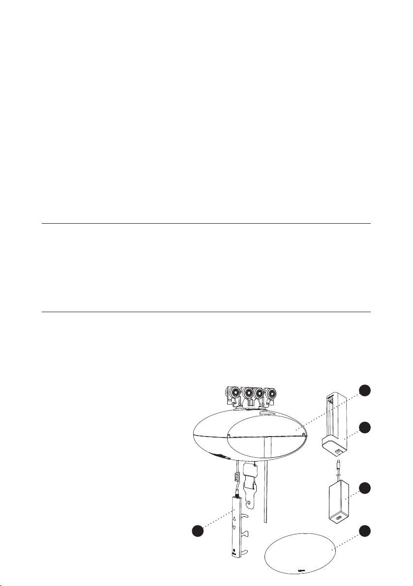
1.06 Unpacking and Preparation
Visual check of the GH1
If the GH1 is thought to be damaged upon reception, the GH1 must not be
used before it has been checked and approved by a qualied person or the
Guldmann Service Team.
Contents of the box
1.
GH1 hoist
2.
Hand control
3.
Transformer
4.
Charging station
5.
Side covers
6.
Manual
7.
Label for rail system
© Guldmann GB/US-1706/12/2016 • # 550865_14
1
4
3
2
5
5
Button for reset of emergency stop
GH1 is delivered with the emergency stop activated in order to ensure that the
battery is not being discharged during long-term storage. Reset the emergency
stop by pressing the “RESET” button on the bottom of the hoist (see point 2.04).
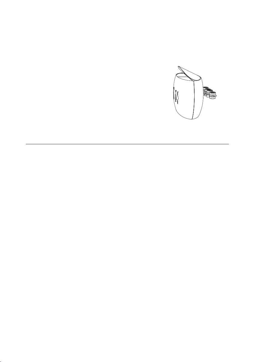
Mounting of side cover
GH1 is standard delivered with side cover in
white and yellow.
Before starting to mount the side cover it is
important, for safety reasons, to make sure
that the emergency stop is activated
(see point 2.04).
The chosen side covers are tted on the side
of GH1 by bending the cover slightly and
placing it in the groove at the side of GH1.
1.07 Installing a new GH1 hoist in an existing rail system
Please notice, when installing a new GH1 hoist in an existing rail system it
must be ensured that:
• The rated max load of the rail system, must be equal or higher than the max
load of the new hoist.
– If there is no max load mentioned on the rail system, the rail system must
then be checked according to the guideline in the installation manual
(distance between bracket according to max load).
– If the brackets are not visible, then a load test with 1,5 x max load of the
hoist must be performed minimum 20 min. During the test the deection of
the rails must not be higher than 1/200 of the length of the rail.
– If it is not possible to do any of the above mentioned, please contact
Guldmann or their representative.
• If the rail system can not be rated to the same max load as the hoist, then
extra brackets must be installed according to the installation manual (distance
between bracket according to max load).
6
© Guldmann GB/US-1706/12/2016 • # 550865_14
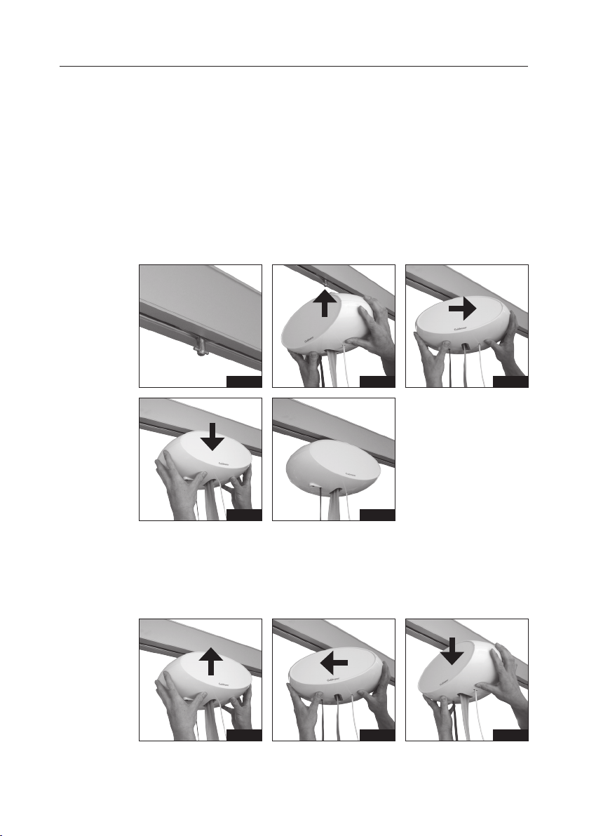
1.08 Installing / deinstalling GH1 Q in the rail
The GH1 Q lifting module has a quick-release system which makes it very
simple to click-on and click-off the lifting module from the rails if it from time to
time is necessary to relocate the lifting module to another room or residence.
The moving of the lifting module can be accomplished without any use of tools.
Installing GH1 Q
1. The travelling trolley is mounted in the rail.
2. Turn GH1 Q 90° in relation to the rail as illustrated and connect it to the
travelling trolley.
3. Turn GH1 Q as illustrated until the hoist is parallel to the rail.
4. Stop pressing up and allow the safety lock to engage.
5. GH1 Q ceiling hoist is now ready to use.
Fig. 1
Fig. 4
Fig. 2
Fig. 5
Deinstalling GH1 Q
1. Press GH1 Q up to release it from the travelling trolley.
2. Turn GH1 Q 90° as illustrated.
3. Release and lift down GH1 Q.
Fig. 1
Fig. 2
Fig. 3
Fig. 3
© Guldmann GB/US-1706/12/2016 • # 550865_14
7

1.09 Power supply
GH1 is equipped with a battery that requires regular recharging. The power
supply for the transformer and the charging station must be connected by
Guldmann Service Team or by a qualied engineer.
The transformer supplied must always be used.
Safety concerning static electricity (ESD)
Service technicians and installers must use an ESD-safety package
consisting of a mat, a ground wire, and a bracelet.
The technician/installer connects the mat to a grounding point, for instance a
radiator or a water pipe. The technician/installer must then put on the bracelet
and connect it to the mat. If it is not possible to nd a grounding point, the
mat and the bracelet must be used as a minimum.
Only then is it allowed to work with the PC Board or components where it
is possible to come into contact with the PC Board.
Class II equipment
Mobile equipment is class II epuipment (marked with double-encassed
symbol) and can be connected to the mains direct by the user.
Equipment is disconnected from Supply Mains by detaching the mains plug
from the wall outlet.
8
© Guldmann GB/US-1706/12/2016 • # 550865_14
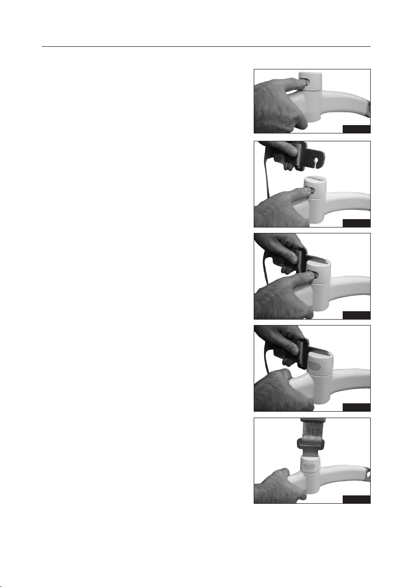
1.10 Installation of the lifting hanger before use
Lifting hangers from other
manufacturers
Guldmann shall not be liable for faults
or accidents that may occur as a result
of using lifting hangers made by other
manufacturers.
If there is any doubt about the selection or use of a lifting hanger, please
contact your supplier.
The lifting hanger can be installed to the
lifting strap without the use of any tools.
1. Hold the lifting hanger in the right hand
and press the yellow button using the
thumb as shown (Fig. 1).
2. Insert the strap attachment in the slot
on the lifting hanger top cover with the
open side facing down (Fig. 2a, 2b) and
release the yellow button (g. 2c).
3. Rotate the strap attachment to a vertical
position (g. 3).
Check that the yellow button has returned to its locked position by checking
that it is ush with the cover of the lifting
hanger and that the strap attachment
can rotate freely.
Fig. 1
Fig. 2a
Fig. 2b
© Guldmann GB/US-1706/12/2016 • # 550865_14
Fig. 2c
Fig. 3
9
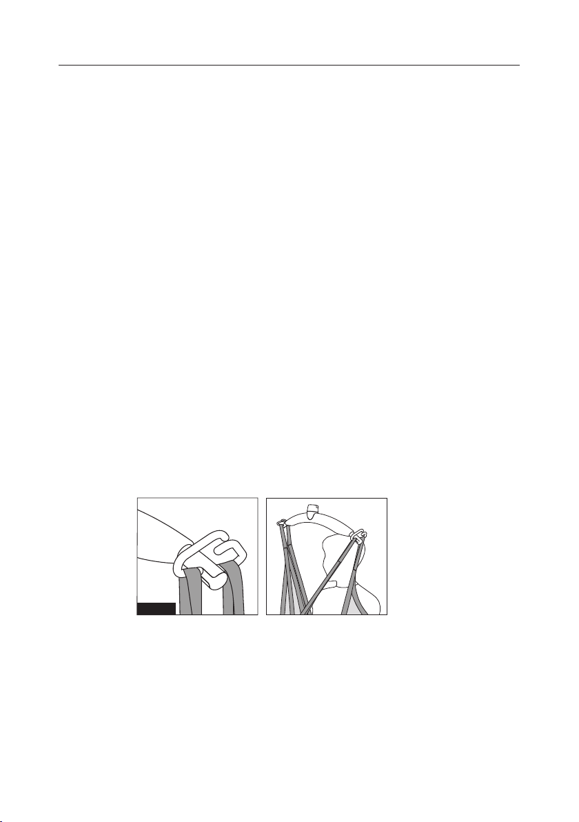
1.11 Lifting sling
A lifting sling with four to eight lifting straps designed for mounting on hooks
should be used when using a Guldmann lifting hanger. Place the straps on
the hooks. Make sure that the rubber safety catch returns to its start position,
so the straps can not unintentionally fall off.
Slings made by other manufacturers
Guldmann shall not be liable for faults or accidents that may occur as a result
of using lifting slings made by other manufacturers.
If there is any doubt about the selection or use of a lifting sling, please
contact your supplier.
Guldmann shall not be liable for faults or accidents due to incorrect use of the
lifting sling, or for reasons of inadequate attention on the part of the carer or
user.
Attaching the lifting sling
Place the straps from the lifting sling on the hooks on the lifting hanger. Start
with the uppermost set of straps (from the back) and then take the lowest set
of straps (from the legs).
GH lifting hanger, 4 attachment points
Caution!
Be careful when attaching the lifting sling’s straps on the hooks. Check
that the straps have been correctly placed in the lifting hanger’s hooks.
When pressing the up button on the hand control to lift the user, check
again that all straps remain correctly placed in the lifting hanger’s
hooks (Fig. 1).
Fig. 1
10
© Guldmann GB/US-1706/12/2016 • # 550865_14
 Loading...