

Page 1
GB/US ........ GH1/GH1 Q Ceiling Hoist
User manual – vers. 14.00
1
Page 2

2
© Guldmann GB/US-1706/12/2016 • # 550865_14
Page 3

GH1/GH1 Q Ceiling Hoist
1.00 .........Purpose and intended use ......................................4
1.01 .........Manufacturer ..................................................4
1.02 .........Intended use ..................................................4
1.03 .........Purpose ......................................................4
1.04 .........Important/Precautions ...........................................4
1.05 .........Load limits on GH1 system .......................................5
1.06 .........Unpacking and Preparation .......................................5
1.07 .........Installing a new GH1 hoist in an existing rail system ...................6
1.08 .........Installing / deinstalling GH1 Q in the rail .............................7
1.09 .........Power supply ..................................................8
1.10 .........Installation of the lifting hanger before use ...........................9
1.11 .........Lifting sling ...................................................10
1.12 .........Swing kit. . . . . . . . . . . . . . . . . . . . . . . . . . . . . . . . . . . . . . . . . . . . . . . . . . . . . 13
1.13 .........Using swing kit in doorway ......................................14
1.14 .........Exchange of side cover .........................................15
2.00 .........Description of functions .......................................15
2.01 .........Pictograms ...................................................16
2.02 .........Indicator lamps and audio signals .................................16
2.03 .........Operation ....................................................16
2.04 .........Safety functions ...............................................18
2.05 .........Accessories ..................................................19
3.00 .........Transport and storage .........................................21
4.00 .........Maintenance and storage ......................................21
4.01 ........Cleaning .....................................................21
4.02 .........Storage .....................................................23
4.03 .........How to prevent/avoid corrosion? ..................................23
4.04 .........The owner’s daily maintenance duty ...............................23
4.05 .........Disposal of the GH1 including battery ..............................23
5.00 .........Service and lifetime ...........................................23
5.01 ........Lifetime .....................................................23
5.02 .........Safety/service inspections .......................................23
5.03 .........Troubleshooting ...............................................24
6.00 .........Classication ................................................24
7.00 .........Technical specications ......................................26
8.00 .........EC-Declaration of conformity ...................................28
9.00 .........Environmental policy statement - V. Guldmann A/S ................29
. . . . . . . . . . . . . USA and countries outside the EU ..............................30
A. ...........Users guide ..................................................30
B. ..........WARRANTY ..................................................30
© Guldmann GB/US-1706/12/2016 • # 550865_14
3
Page 4

1.00 Purpose and intended use
1.01 Manufacturer
V. Guldmann A/S
Graham Bells Vej 21-23A
DK-8200 Aarhus N
Tlf. + 45 8741 3100
Fax + 45 8741 3131
www.guldmann.com
1.02 Intended use
GH1 is a lifting module that covers the need for lifting and moving a person
with disabilities, and for walking training.
GH1 is intended for use in hospitals, nursing homes, rehabilitation centres
and in private homes and buildings.
1.03 Purpose
GH1 is a hoist which covers the need for lifting or moving a person with
disabilities in the home care sector, nursing homes, rehabilitation centres,
riding schools and swimming pools.
Conditions for use
The use of the GH1 is subject to the following:
• The GH1 should only be used by trained personnel.
• The maximum nominal load, 175 kg (385 lbs), 205 kg (450 lbs), 255 kg (560
lbs) respectively, must not be exceeded (section 1.05).
• The instruction offered by Guldmann to all customer groups in connection
with the purchase of a ceiling-mounted hoist has been received.
• The helper pays attention to the well-being of the user when using the hoist.
• The hoist is used in rail systems which are installed, tested and approved
according to DS/EN 10535 and Guldmann’s stipulations.
• Only technicians who have been certied by Guldmann may install and test
the rail systems.
• The hoist is used with a Guldmann lifting hanger (section 1.10).
• The hoist is used with a Guldmann lifting sling or with other suitable slings
(section 1.11).
1.04 Important/Precautions
• Read the instructions carefully before using the hoist and in connection with
cleaning and service of the hoist.
• The hoist’s maximum load must never be exceeded.
• The hoist may only be used to lift a person.
• The red strap for the emergency stop and the emergency lowering must be
adjusted to the helper’s reach, and must not be removed.
4
© Guldmann GB/US-1706/12/2016 • # 550865_14
Page 5
• If a defect appears during use of the hoist, stop using the hoist and contact
the Guldmann Service Team for repairs.
• The hoist is controlled by a microprocessor PCB, which can be damaged by
static electricity if touched without the necessary precautions, (see point 1.09)
The electronics may only be serviced by Guldmann approved service technicians.
• For safety reasons the side cover may only be dismantled when the emergency stop is activated (see point 2.04).
• The user may not hold their hands around the lifting strap during lift and
transfer.
• The lifting hanger must not be mounted or replaced when the hoist is positioned over the patient.
Re: EMC
If electromagnetic or other inuences occur between this product and other
products, these products must not be used together.
1.05 Load limits on GH1 system
Read the label which indicates the maximum load limits for each component.
The component, e.g. lifting hanger, lifting sling, etc. labelled with the lowest
load limit determines the maximum load limit for the entire system.
This maximum load limit must not be exceeded.
Please note that the max load may change when different components are
used, such as lifting hangers, lifting slings, etc.
1.06 Unpacking and Preparation
Visual check of the GH1
If the GH1 is thought to be damaged upon reception, the GH1 must not be
used before it has been checked and approved by a qualied person or the
Guldmann Service Team.
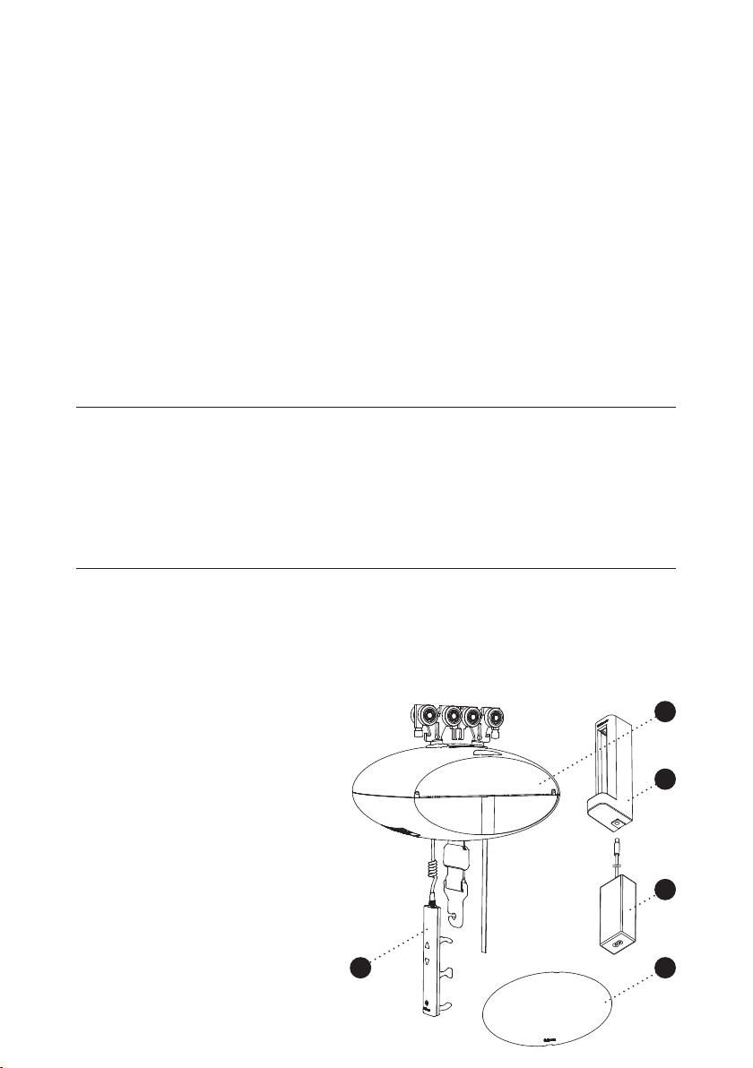
Contents of the box
1.
GH1 hoist
2.
Hand control
3.
Transformer
4.
Charging station
5.
Side covers
6.
Manual
7.
Label for rail system
© Guldmann GB/US-1706/12/2016 • # 550865_14
1
4
3
2
5
5
Page 6
Button for reset of emergency stop
GH1 is delivered with the emergency stop activated in order to ensure that the
battery is not being discharged during long-term storage. Reset the emergency
stop by pressing the “RESET” button on the bottom of the hoist (see point 2.04).
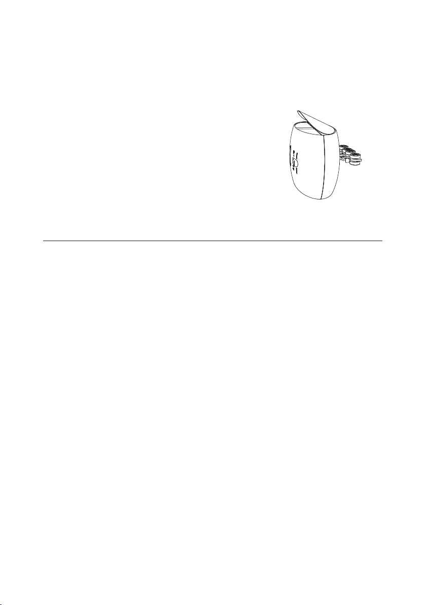
Mounting of side cover
GH1 is standard delivered with side cover in
white and yellow.
Before starting to mount the side cover it is
important, for safety reasons, to make sure
that the emergency stop is activated
(see point 2.04).
The chosen side covers are tted on the side
of GH1 by bending the cover slightly and
placing it in the groove at the side of GH1.
1.07 Installing a new GH1 hoist in an existing rail system
Please notice, when installing a new GH1 hoist in an existing rail system it
must be ensured that:
• The rated max load of the rail system, must be equal or higher than the max
load of the new hoist.
– If there is no max load mentioned on the rail system, the rail system must
then be checked according to the guideline in the installation manual
(distance between bracket according to max load).
– If the brackets are not visible, then a load test with 1,5 x max load of the
hoist must be performed minimum 20 min. During the test the deection of
the rails must not be higher than 1/200 of the length of the rail.
– If it is not possible to do any of the above mentioned, please contact
Guldmann or their representative.
• If the rail system can not be rated to the same max load as the hoist, then
extra brackets must be installed according to the installation manual (distance
between bracket according to max load).
6
© Guldmann GB/US-1706/12/2016 • # 550865_14
Page 7
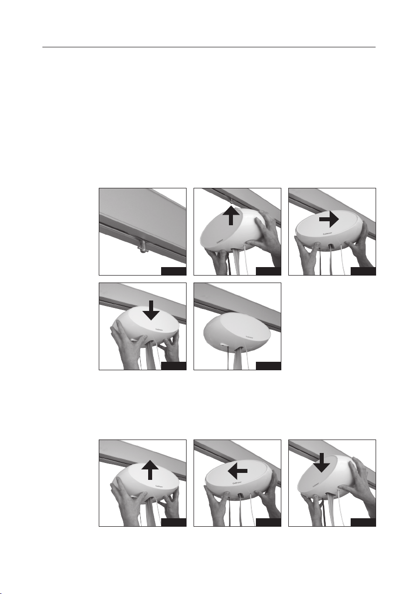
1.08 Installing / deinstalling GH1 Q in the rail
The GH1 Q lifting module has a quick-release system which makes it very
simple to click-on and click-off the lifting module from the rails if it from time to
time is necessary to relocate the lifting module to another room or residence.
The moving of the lifting module can be accomplished without any use of tools.
Installing GH1 Q
1. The travelling trolley is mounted in the rail.
2. Turn GH1 Q 90° in relation to the rail as illustrated and connect it to the
travelling trolley.
3. Turn GH1 Q as illustrated until the hoist is parallel to the rail.
4. Stop pressing up and allow the safety lock to engage.
5. GH1 Q ceiling hoist is now ready to use.
Fig. 1
Fig. 4
Fig. 2
Fig. 5
Deinstalling GH1 Q
1. Press GH1 Q up to release it from the travelling trolley.
2. Turn GH1 Q 90° as illustrated.
3. Release and lift down GH1 Q.
Fig. 1
Fig. 2
Fig. 3
Fig. 3
© Guldmann GB/US-1706/12/2016 • # 550865_14
7
Page 8

1.09 Power supply
GH1 is equipped with a battery that requires regular recharging. The power
supply for the transformer and the charging station must be connected by
Guldmann Service Team or by a qualied engineer.
The transformer supplied must always be used.
Safety concerning static electricity (ESD)
Service technicians and installers must use an ESD-safety package
consisting of a mat, a ground wire, and a bracelet.
The technician/installer connects the mat to a grounding point, for instance a
radiator or a water pipe. The technician/installer must then put on the bracelet
and connect it to the mat. If it is not possible to nd a grounding point, the
mat and the bracelet must be used as a minimum.
Only then is it allowed to work with the PC Board or components where it
is possible to come into contact with the PC Board.
Class II equipment
Mobile equipment is class II epuipment (marked with double-encassed
symbol) and can be connected to the mains direct by the user.
Equipment is disconnected from Supply Mains by detaching the mains plug
from the wall outlet.
8
© Guldmann GB/US-1706/12/2016 • # 550865_14
Page 9
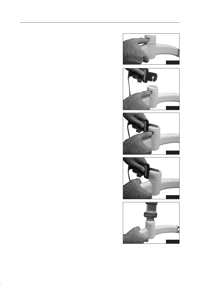
1.10 Installation of the lifting hanger before use
Lifting hangers from other
manufacturers
Guldmann shall not be liable for faults
or accidents that may occur as a result
of using lifting hangers made by other
manufacturers.
If there is any doubt about the selection or use of a lifting hanger, please
contact your supplier.
The lifting hanger can be installed to the
lifting strap without the use of any tools.
1. Hold the lifting hanger in the right hand
and press the yellow button using the
thumb as shown (Fig. 1).
2. Insert the strap attachment in the slot
on the lifting hanger top cover with the
open side facing down (Fig. 2a, 2b) and
release the yellow button (g. 2c).
3. Rotate the strap attachment to a vertical
position (g. 3).
Check that the yellow button has returned to its locked position by checking
that it is ush with the cover of the lifting
hanger and that the strap attachment
can rotate freely.
Fig. 1
Fig. 2a
Fig. 2b
© Guldmann GB/US-1706/12/2016 • # 550865_14
Fig. 2c
Fig. 3
9
Page 10
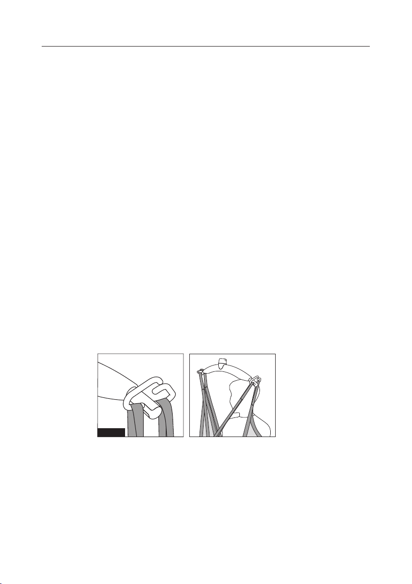
1.11 Lifting sling
A lifting sling with four to eight lifting straps designed for mounting on hooks
should be used when using a Guldmann lifting hanger. Place the straps on
the hooks. Make sure that the rubber safety catch returns to its start position,
so the straps can not unintentionally fall off.
Slings made by other manufacturers
Guldmann shall not be liable for faults or accidents that may occur as a result
of using lifting slings made by other manufacturers.
If there is any doubt about the selection or use of a lifting sling, please
contact your supplier.
Guldmann shall not be liable for faults or accidents due to incorrect use of the
lifting sling, or for reasons of inadequate attention on the part of the carer or
user.
Attaching the lifting sling
Place the straps from the lifting sling on the hooks on the lifting hanger. Start
with the uppermost set of straps (from the back) and then take the lowest set
of straps (from the legs).
GH lifting hanger, 4 attachment points
Caution!
Be careful when attaching the lifting sling’s straps on the hooks. Check
that the straps have been correctly placed in the lifting hanger’s hooks.
When pressing the up button on the hand control to lift the user, check
again that all straps remain correctly placed in the lifting hanger’s
hooks (Fig. 1).
Fig. 1
10
© Guldmann GB/US-1706/12/2016 • # 550865_14
Page 11
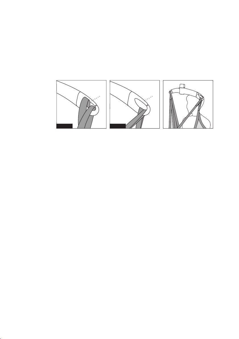
GH Lifting hanger
Caution!
Be careful when attaching the lifting sling on the hooks. Check that the
straps have been pulled completely through the rubber safety catch
(A) and into place in the lifting hanger’s hooks. When pressing the up
button to lift the user, check again that all the straps remain correctly
placed in the lifting hanger’s hooks (g. 1a and g. 1b).
AA
Fig. 1a Fig. 1b
Lifting to and from a seated position
When lifting a user from e.g. a wheelchair, move the GH1 towards the person
to be lifted. The lifting hanger should be at the same height as the user’s
chest and should not be moved further in over the user than to approximately
mid-thigh position.
Place the lifting hanger parallel to the user’s shoulders.
Place the lifting sling behind the user’s back between the back of the chair
and the user’s back. The center marks of the lifting sling should follow the
user’s spine.
Lead the leg straps along the outer sides of the user’s shins and beneath
the thighs between the hollow of the knees and the hip joints. Cross the leg
straps in front of the user.
All four lifting straps are now ready to be attached. The lifting sling can now
be mounted on the lifting hanger.
Lifting to and from lying position in bed
Bring the lifting hanger over the centre of the person to be lifted. Place the
lifting hanger parallel to the user’s shoulders.
Turn the user onto his or her side. The Basic High sling should be placed so
that its top is at the same height as the top of the user’s head. Now position
the sling over the user so that the center marks follow the user’s spine. Turn
the user onto his or her back and pull out the remaining part of the lifting
sling. Place the leg straps beneath the user’s thighs and cross them. All four
lifting straps are now ready to be attached and the lifting sling can now be
mounted on the lifting hanger. It is an advantage to elevate the head of the
bed so that the user is sitting up.
© Guldmann GB/US-1706/12/2016 • # 550865_14
11
Page 12

For further information, please refer to the user manual for the lifting sling in
question.
Important!
Only persons who have received competent instruction regarding the use of
lifting equipment and tting of slings should use the hoist.
Plan the move. Avoid leaving the user in the lifting sling unattended.
The hoist lifts quickly and powerfully. Before lifting, check that the user is
completely free of his/her surroundings. The user’s head, arms, hands and
feet must not be in danger of becoming trapped. Be careful with any tubes
and wires that are attached to the user. The user should not hold the lifting
strap during the moving procedure as there is a risk of crushing between
the strap’s hook and the hoist. Check that the hand control and hand control
cable is free of hanger, patient and other object before the hoist is activated
up or down moved.
If the hoist is used correctly, the user should only be lifted to the extent that
she/he is clear of the surface and should be moved at this height.
12
© Guldmann GB/US-1706/12/2016 • # 550865_14
Page 13
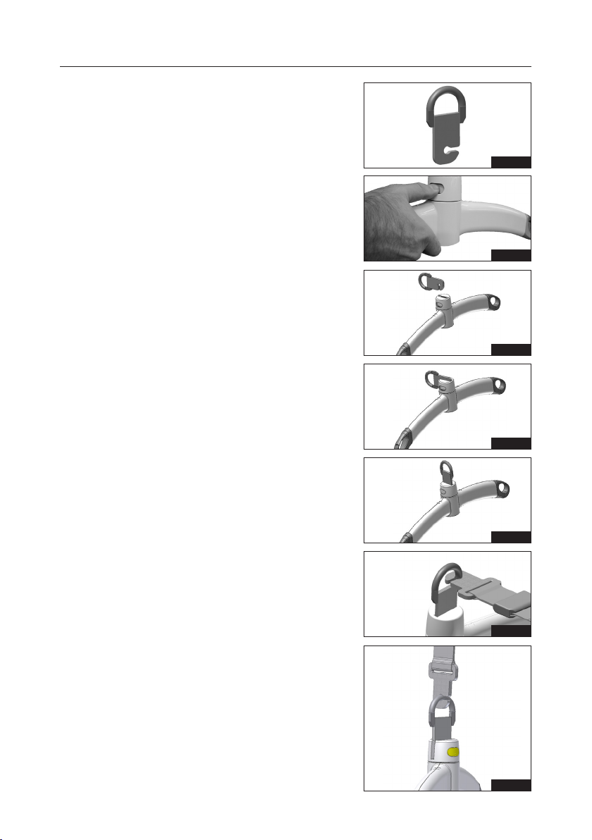
1.12 Swing kit
The swing function is used in conjunction with a transfer e.g. through a door
from one lifting module to another.
Note: The swing adapter must be
ordered separately.
Installation of swing adapter
1. Before starting a lift involving a swing
transfer the swing adapter (Fig. 1) must
be installed on the lifting hanger.
(g. 2 til 5).
2. Hold the lifting hanger in the right hand
and press the yellow button using the
thumb (g. 2).
3. Insert the swing adapter in the slot on
the lifting hanger top cover with the
open side facing down (Fig. 3a, 3b) and
release the yellow button.
4. Rotate the swing adapter to a vertical
position (g. 4).
Check that the yellow button has returned to its locked position by checking
that it is ush with the cover of the lifting
hanger and that the swing adapter can
rotate freely.
5. Install the strap attachment to the swing
adapter by sliding the open side of the
strap attachment over the at area of
the swing adapter (g. 5).
Fig. 1
Fig. 2
Fig. 3a
Fig. 3b
Fig. 4
6. Rotate the strap attachment and ensure
that it moves up on the circular portion
of the swing adapter (g. 6).
© Guldmann GB/US-1706/12/2016 • # 550865_14
Fig. 5
Fig. 6
13
Page 14
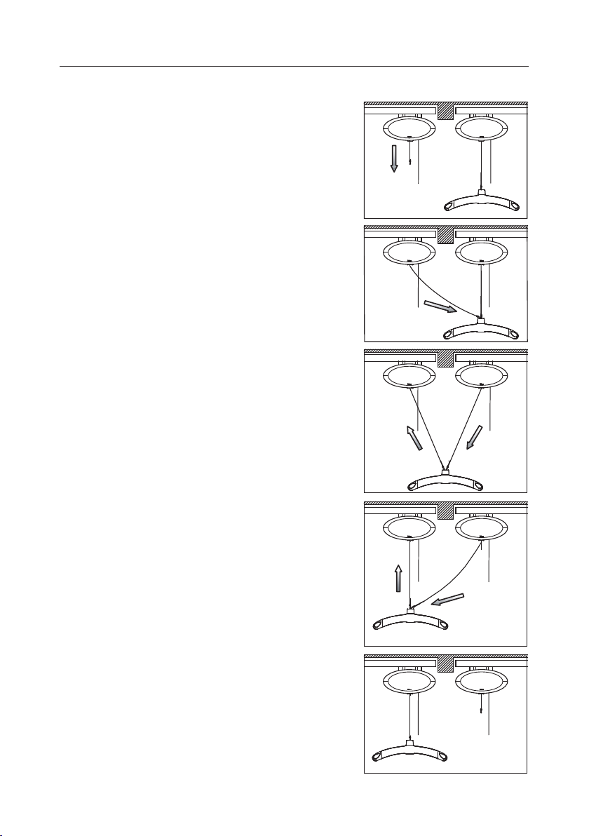
1.13 Using swing kit in doorway
1. Bring the two hoists as close together
as possible. Adjust the height of the
lifting hanger on hoist B so that the
transfer can be done without the user
touching the oor during the transfer
from one hoist to another.
2. Take the free lifting strap from hoist A
and secure it to the swing adapter on
the lifting hanger (see 1.10 gures 5
and 6).
In order to lower the free lifting strap on
hoist A a slight pull must be applied to
the strap.
3. Lower the lifting hanger using hoist B
while lifting the strap on hoist A to perform the swing transfer. The transfer
has been completed when there is no
load on the lifting strap on hoist B.
4. Disconnect the lifting strap on hoist B
from the lifting hanger and raise the
strap on hoist B out of the way.
5. Move the lifting hanger from hoist A to
operating height and the doorway transfer is complete.
A B
A B
A B
Note: There must be a load on the
lifting strap corresponding to the weight
of Guldmann’s lifting hanger before
GH1’s lowering function will operate.
14
A B
A B
© Guldmann GB/US-1706/12/2016 • # 550865_14
Page 15
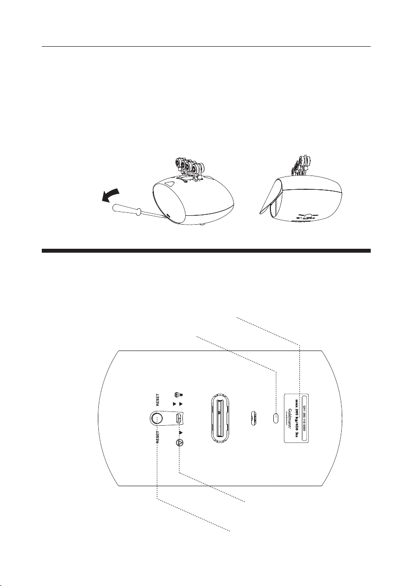
1.14 Exchange of side cover
If you want to change the appearance of GH1, the side cover can be exchanged
or turned. Before starting to mount the side cover it is important, for safety reasons, to make sure that the emergency stop is activated (see point 2.04).
The side cover is dismantled by inserting for instance a at screwdriver in the
opening between the groove and the cover and tilt the cover upwards and out.
The side cover is tted on the side of GH1 by bending the cover slightly and
placing it in the groove on the side of GH1.
2.00 Description of functions
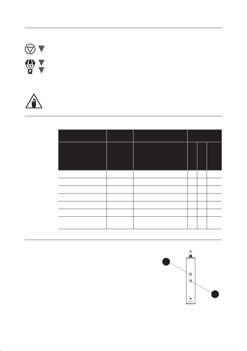
Information panel on the GH1 bottom surface.
Designation of type and maximum load
Green/yellow indicator lamp
© Guldmann GB/US-1706/12/2016 • # 550865_14
Strap for activating emergency stop
and emergency lowering device
Button for resetting the emergency stop
15
Page 16
2.01 Pictograms
Emergency stop
Emergency lowering function
RESET
Reset emergency stop
Danger - rotating parts
2.02 Indicator lamps and audio signals
Status Indicator
Off – stand by Off
All OK Green
Low battery Yellow
Fault on hoist Yellow Beeps at button activation
Battery critical low Yellow
Over load Green Beeps at button activation
Hand control placed in
charging station
lamps
On 3 beeps for charging
2.03 Operation
Audio signals Possible GH1
Functions
Up
Down
lowering
Emergency
Hand control
The GH1 is switched on automatically when
1
a button on the hand control is pressed.
The GH1 is switched off automatically after
approx. 8 minutes without activation.
GH1
1. Lift
2. Lower
Note: There must be a load on the lifting strap corresponding to the weight of
Guldmann’s lifting hanger before GH1’s lowering function will operate.
16
2
© Guldmann GB/US-1706/12/2016 • # 550865_14
Page 17
Charging / connection
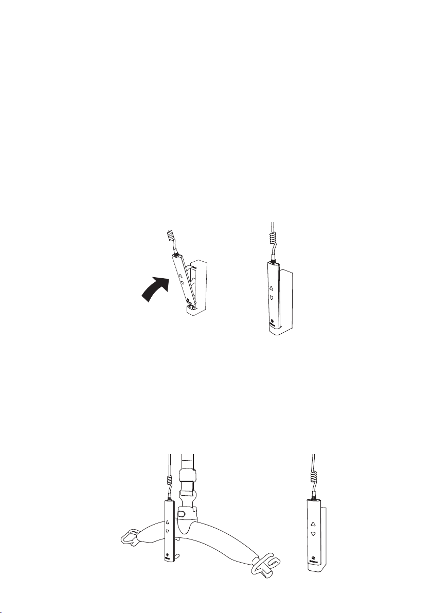
GH1 is recharged when the hand control is placed in the charging station.
Always leave the hand control in the charging station when GH1 is not in use.
This guarantees GH1 functionality and maintains the battery to ensure a long
lifetime.
The transformer must be connected and switched on before charging can
take place. A green indicator lamp on the transformer indicates it is connected
and switched on.
Tilt the hand control and place it on the two pins on the charging station.Then
push the rubber handle into the opening of the charging station. A click indicates that the hand control is placed correctly.
When the hand control is correctly placed in the charging station, you will receive
an acoustic signal of 3 beeps. This means that the hoist is now charging.
The indicator lamp on the bottom of the hoist turns yellow if the charge status
becomes low. The GH1 then has a limited number of lifts available at a time
and must be recharged.
Placing of the hand control
When GH1 is not in use the hand control must always be placed in the charging station. The hand control can also be placed on the lifting hanger if this
is necessary in connection with a transfer.
© Guldmann GB/US-1706/12/2016 • # 550865_14
17
Page 18
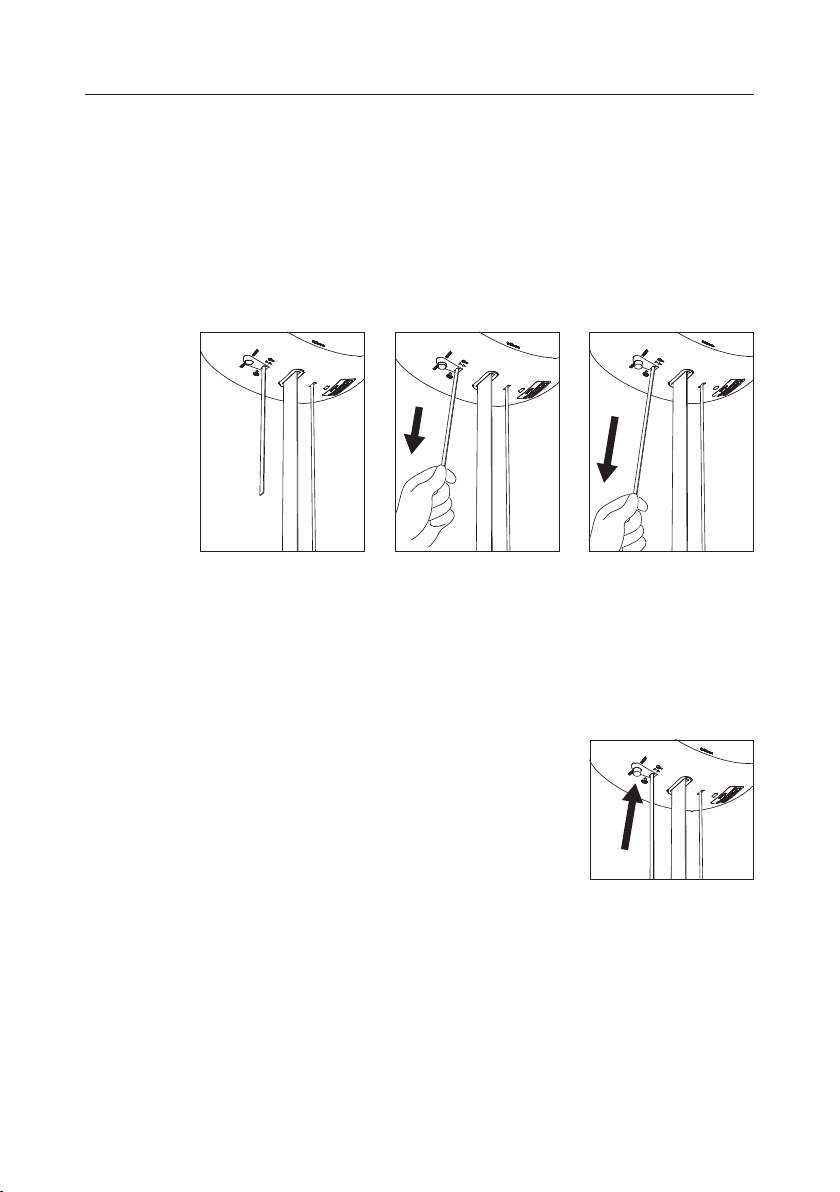
2.04 Safety functions
The emergency stop and emergency lowering device should only be
used in an emergency. In the event that it is necessary to use the safety func-
tions, the fault must be identied and rectied before the GH1 is taken into
use again. Please contact your supplier.
Emergency stop and lowering strap
The red strap has the following functions:
• One pull: Emergency stop is activated.
• Constant pull: Emergency lowering is activated.
Emergency stop
If the GH1 does not stop/react to the hand control when the GH1 is in
use, pull the red strap and the lifting/lowering functions (except emergency
lowering) are deactivated.
When the emergency stop is activated, the hoist will not function. The green
lamp is switched off.
Reset emergency stop
Reset the emergency stop by pressing the yellow
button on the bottom of the hoist.
The yellow button that appears when the emergency stop is pulled, must be pressed manually
before the GH1 is ready for use.
After deactivating the emergency stop, activate the
hand control twice.
Emergency lowering function, electric
If the GH1 fails, the electrical emergency lowering function is used to lower
the user safely. The emergency lowering function is operated by a constant
pull on the red strap that is used for the emergency stop.
When releasing the red strap, the emergency lowering function will be
replaced by the emergency stop.
18
© Guldmann GB/US-1706/12/2016 • # 550865_14
Page 19
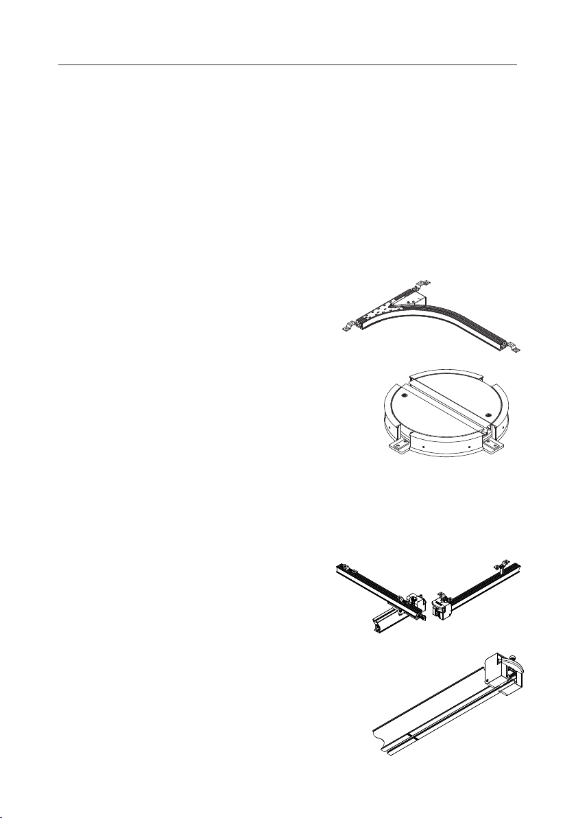
2.05 Accessories
Guldmann – Lifting slings and hangers
Obtain a product catalogue from Guldmann, or see our product range at
www.guldmann.com where it is also possible to watch a video about the use
of lifting slings and to download user manuals for our products.
Extension strap
The extension strap is used where the distance between the lower part of the rails
and the oor exceeds 3.5 m. The extension strap is available as an accessory.
Swing adapter
The swing function is used in conjunction with a transfer, e.g. through a door
from one lifting module to another.
Switch track, electrical
(Must not be used with GH1 Q)
A switch track can be used in rail
systems where it is used to change
direction.
Turntable
The turntable is used in rail systems where
the hoist needs to run in several directions.
The GH1 hoist is placed in the center of the
turntable. By pressing the switch, the turntable rotates 90°. Press again, and the
turn table returns to the rst position.
Safety
This product is mechanically protected
against derailing and jamming.
GH Combi-lock, automatic
(Must not be used with GH1 Q)
Intended use
The Combi-lock is used to move a
person from one rail system to another.
Purpose
Use the Combi-lock when connecting one rail
system to another.
The Combi-lock enables a secure
connection to be made between two rail
systems, e.g. when operating from a singletrack rail system in the bedroom to a roomcovering system in the bathroom.
© Guldmann GB/US-1706/12/2016 • # 550865_14
19
Page 20

The Combi-lock requires no manual operations.
Using the Combi-lock
When activating the Combi-lock, position the traverse rail opposite the xed
rail, where the locking mechanism is automatically activated (the rail systems
lock together). Now it is possible to run the hoist from one rail system to the
other. When the traverse rail is moved away from the xed rail, the locking
mechanisms are re-activated to secure the hoist and prevent it from running
off the rail. The hoist must always be run completely past the Combi-lock
before the traverse rail is moved away (the Combi-lock must be visible).
The rail systems are optimally connected at a max. distance of 1000 mm
between the hoist and the Combi-lock; you may also refer to the marking
label on the rail. At this distance, a secure and easy connection can be made.
At a distance greater than 1000 mm, it is more difcult to position the two rail
systems opposite one another. Please note that the connection works regardless of the position of the hoist in relation to the Combi-lock.
Safety
• In the event of an error while using the Combi-lock, discontinue its use.
Contact the Guldmann Service Team or a certied technician to perform any
necessary repairs. A defective Combi-lock can result in injury to both the user
and helper.
• The locking mechanism in the Combi-lock must not be manually activated.
• The Combi-lock is mechanically secured to prevent de-railing and crushing.
• Do not touch the Combi-lock during activation/deactivation
Cleaning
See section 4.01
Daily maintenance
Ensure that the Combi-Lock is intact. Do not use the Combi-lock if it is
damaged or defective. Instead, contact the Guldmann Service Team or a
certied technician, as per Guldmann’s instructions.
Battery
NiMH Battery 24V/2000mAh, Guldmann type number 550574.
Power supply
Power supply, Guldmann item number 554204.
20
© Guldmann GB/US-1706/12/2016 • # 550865_14
Page 21
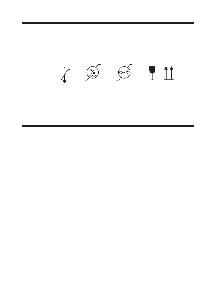
3.00 Transport and storage
Guldmann recommends that the products are always transported and stored
in the original packaging.
Key to symbols on the packaging:
40ºC
104ºF
-10ºC
14ºF
30%
The products should be stored at:
– Temperatures between -10 and +40°C / 14 and 104°F
– A relative air humidity of between 30 and 70 %
– An air pressure of between 700 and 1060 hPa
– This side up
4.00 Maintenance and storage
4.01 Cleaning
We recommend that the product and the parts that patients and caregivers can
come in contact with are cleaned with Novadan Des Wipes or Novadan Desinfect O.
Desinfect O: A broad-spectrum disinfectant system as tablets. Suitable for
disinfection of equipment, tools and surfaces in the healthcare sector.
Novadan Des Wipes: Is a disposable wipe for cleaning and disinfection of all
types of surfaces, machines and instruments in the healthcare sector.
NB: Do never clean the hoist, hanger, trolley, rails etc. with strong acid, base
or alcohol. Never clean the hoist in an autoclave.
70%
106 kPa
70 kPa
© Guldmann GB/US-1706/12/2016 • # 550865_14
21
Page 22
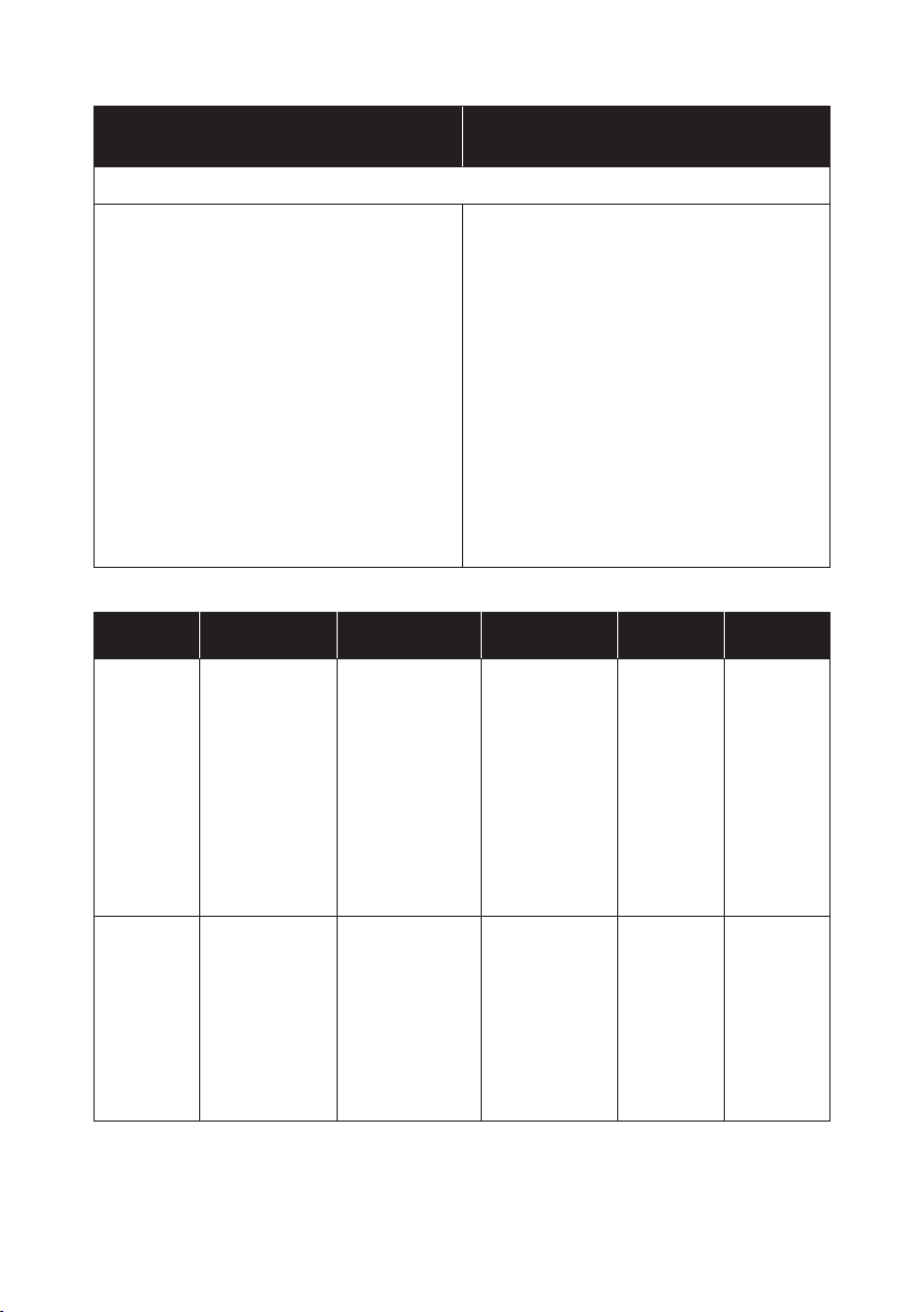
Desifect O
is effective against:
Microbial- & Virus test
• Staphylococcus aureus
(ATCC 6538) (EN 13697:2001)
• Enterococcus hirae
(ATCC 10541) (EN 13697:2001)
• Escherichia coli
(ATCC 10536) (EN 13697:2001)
• Pseudomonas aeruginosa
(ATCC 15442) (EN 13697:2001)
• Candida albicans
(ATCC 10231) (EN 13697:2001)
• Swine plague - Bovine viral diarrhea virus (BVDV)
(EN 14675:2006)
• Swine and avian ue (Inuenza A virus H1N1)
(EN 14675:2006)
Novadan Des Wipes
is effective against:
• Staphylococcus aureus
• Escherichia coli
• Proteus mirabilis
• Pseudomonas aeruginosa
• Candida albicans
• MRSA
• H1N1
• HBV (HIV)
• HCV
Novadan
Description Microbial and
product
Desinfect O A broad-spec-
trum disinfectant
system as
tablets.
Novadan
Des Wipes
Is a disposable
wipe for cleaning
and desinfection of all types
of surfaces,
machines and
instruments
within the healthcare sector and
food industry.
Virus test
Staphylococcus
aureus, Enterococcus hirae,
Escherichia coli,
Pseudomonas
aeruginosa,
Candida albicans,
Swine plague
- Bovine viral
diarrhea virus
(BVDV), Swine
and avian u.
(Inuenza A virus
H1N1)
Staphylococcus
aureus, Escherichia coli, Proteus
mirabilis
Pseudomonas
aeruginosa,
Candida albicans,
MRSA, H1N1
HBV (HIV), HCV
22
Application Dosing Frequency
Tools apparatus
(Remember to
wash afterwards)
1 tablet –10 l
of water
Daily/
periodically
Time before
effect: 5 min.
Lifting pool
with adjustable
handle, bed
guard, remote
control of beds,
extension piece
for bed guards,
Time before
effect: 1 min.
Apart from
H1N1:
30 min
After every
touching
handle, polyester
line for lifting
pool.
© Guldmann GB/US-1706/12/2016 • # 550865_14
Page 23

4.02 Storage
See 3.00
For long-term storage of GH1 the emergency stop must be activated. This
ensures that the battery is not being discharged.
4.03 How to prevent/avoid corrosion?
When the products are mainly used in an corrosive environment, e.g. swimming pool, the products must be ordered with a special corrosion-preventive
surface treatment. The preventive surface treatment must be replicated minimum anually.
4.04 The owner’s daily maintenance duty
Check the lifting sling for wear and damage before use.
Do not use the lifting sling if it is damaged or defective.
Do not use GH1 if the lifting strap or the rubber safety catch of the lifting
hanger are damaged or defective.
Contact your supplier and order a new lifting sling or a replacement of the
lifting strap. Replacement of the lifting strap must only be performed by the
Guldmann Service Team or by a qualied technician in accordance with Guldmann’s instructions.
4.05 Disposal of the GH1 including battery
Local and national regulations on environmentally correct recycling must be
observed. Batteries (type NiMH) must always be delivered to an approved
recycling point.
5.00 Service and lifetime
5.01 Lifetime
The products have an expected lifetime of 15 years, on the condition of
correct use and correct service inspections, see section 5.02.
Replacement of components
Replacement of batteries, PCBs and lifting straps must be performed by a
qualied service technician or the Guldmann Service Team.
5.02 Safety/service inspections
In accordance with international standard EN/ISO 10535 “Hoist for the
transfer of disabled persons – Requirements and test methods” an inspection
should be performed on the hoist at least once a year.
Guldmann recommends that regular safety/service inspection is performed at
least once a year with regard to the pattern of usage.
© Guldmann GB/US-1706/12/2016 • # 550865_14
23
Page 24
Safety/service inspections of the products must be performed by a qualied
service technician or the Guldmann Service Team. In connection with the
purchase Guldmann may offer a service agreement for this inspection.
During the safety/service inspection a report must be prepared on what was
checked and replaced. Parts that are worn or defective must be replaced with
new parts from Guldmann. Spare parts drawings and documentation can be
obtained from the manufacturer or supplier.
Documentation/checklist regarding safety/service inspection can be obtained
from the manufacturer or supplier.
5.03 Troubleshooting
The GH1 does not respond to the hand control’s keys
1. Check that the emergency stop is not activated (see section 2.04).
2. Check that GH1 has power supply and that the battery is recharged
(see section 2.02).
3. Check that the transformer is switched on and connected to the charging
station.
4. Place the hand control in the charging station and recharge GH1
(see section 2.03).
5. Contact the Guldmann Service Team if the fault cannot be found and
corrected.
6.00 Classication
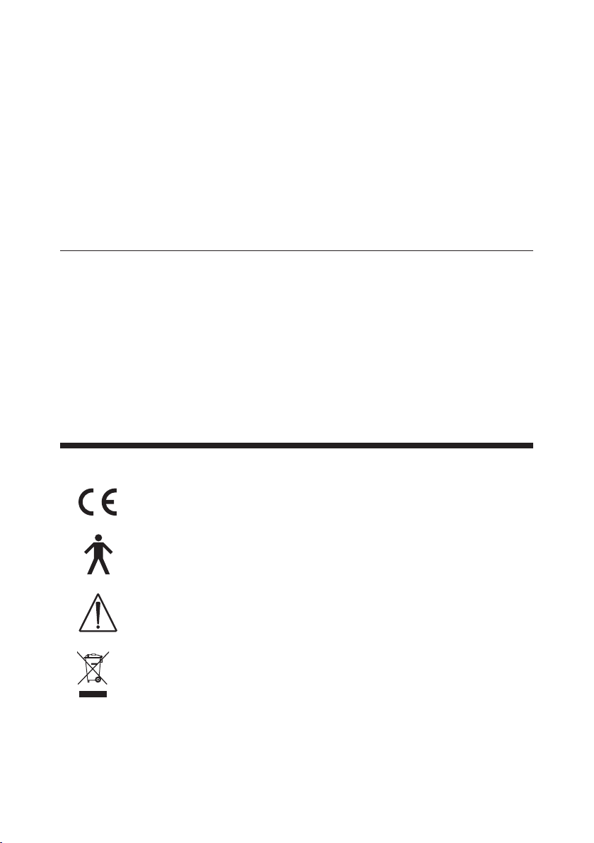
CE marking
Type B in accordance with IEC/EN 60601-1
Read the manual before use
Must not be disposed of as standard household waste, must be recycled.
24
© Guldmann GB/US-1706/12/2016 • # 550865_14
Page 25
Part no. xxxxxx
Edition xxx
Date xxxx-xx-xx
IP44
Part no. xxxxxx
Edition xxx
Prod. date yyyy-mm-dd
Serial no. xx xxx
max
xxx kg/xxx lbs
V. Guldmann A/S
www.guldmann.com
Barcode 128C
Part no. xxxxxx
Prod. date yyyy-mm-dd
Serial no. xxxxx
33V AC, 2.5 A, IP44
CONTINUOUS OPERATION
WITH SHORT-TIME LOADING
Barcode 128C
max 205 kg / 450 lbs
www.guldmann.com
INTERNALLY POWERED
EQUIPMENT 24V DC
GH1 205 110 0000
max 205 kg / 450 lbs
www.guldmann.com
GH1 205 110 0000
Class 2 equipment .....Non-permanent installation without protective ground
The equipment is not suitable for use in the presence of ammable mixtures.
Degree of protection against harmful ingress of liquids (water)
Lifting module. . . . . . . . . . . . . . . . . . . . . . . . . . . . . . . . . . . . . . . . . . . . . . . IP 44
Hand control. . . . . . . . . . . . . . . . . . . . . . . . . . . . . . . . . . . . . . . . . . . . . . . . IP 44
Charging station .............................................IP 20
Power supply ...............................................IP 20
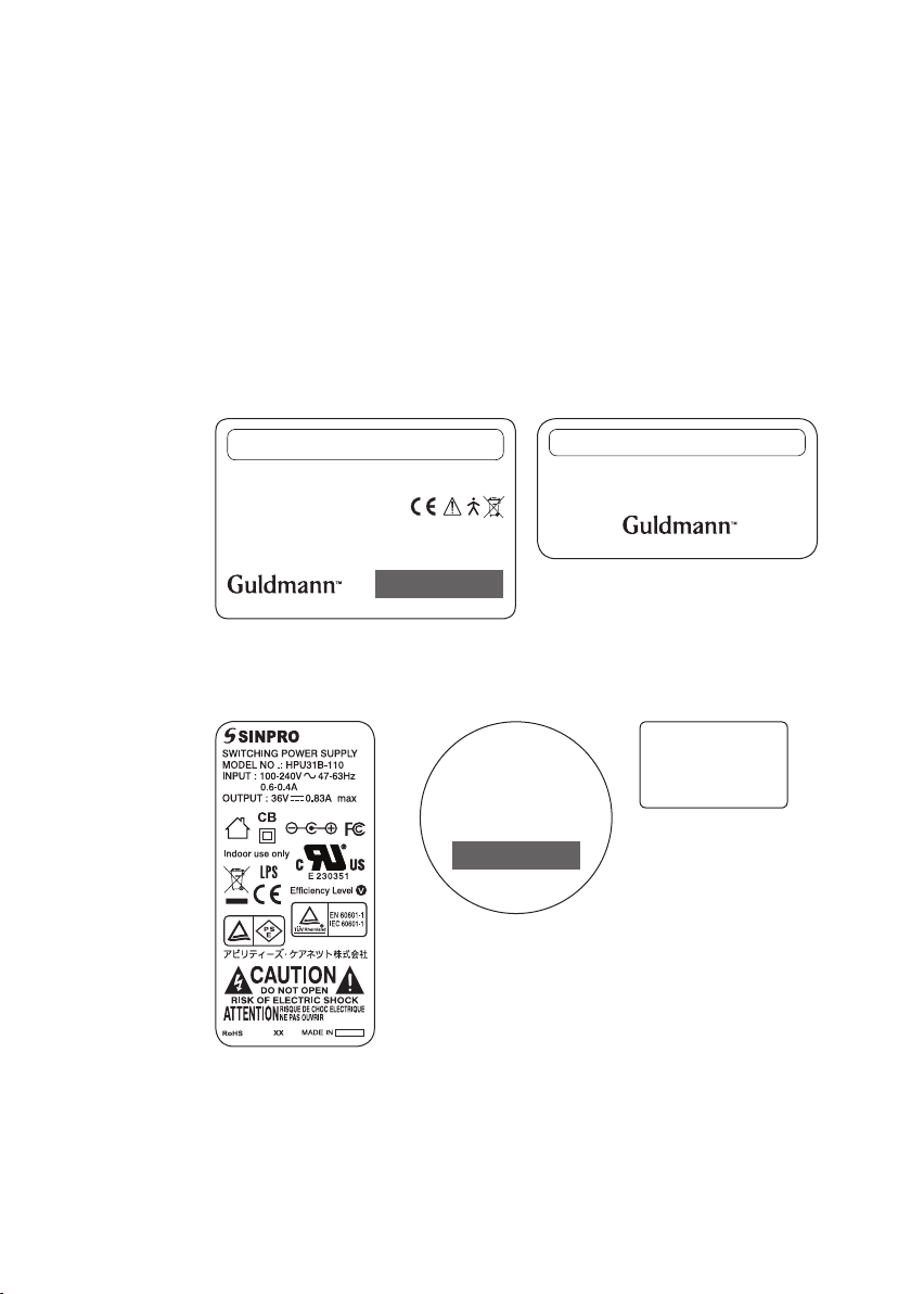
Examples of labels
Lifting module
Power supply Lifting hanger Hand control
© Guldmann GB/US-1706/12/2016 • # 550865_14
25
Page 26
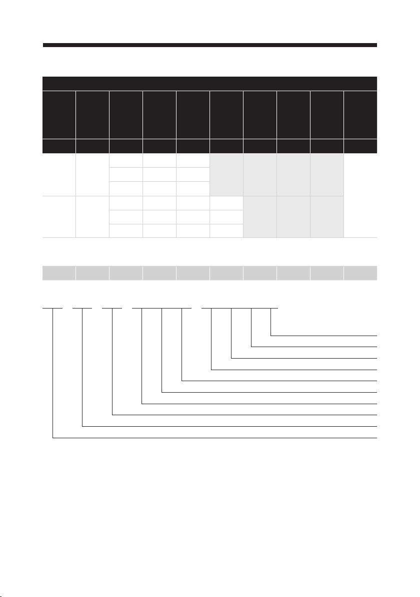
7.00 Technical specications
GH1 Lifting modules, congurations
Guldmann
hoist type
GH1 (x) xxx x x x x x x x
GH1 175 1 1 Hand
GH1 Q 175 1 1 5
Product
line
Load inkgNumber
of lifting
straps
205 1 1
255 1 1
205 1 1 5
255 1 1 5
Number
of lifting
motors
Additional
functions
Scale
module
CLM
module
Service
module
User
interface
control : 0
Example: GH1 205 110 0000
GH1 205 1 1 0 0 0 0 0
GH1 205 1 1 0 0 0 0 0
Hand control
N/A
N/A
N/A
N/A
1 lifting motor
1 lifting strap
Safe Working Load SWL: 205 kg
–
Ceiling hoist, type GH1
26
© Guldmann GB/US-1706/12/2016 • # 550865_14
Page 27
Functions
A
G
Lifting capacity, SWL ....175 kg (385 lbs), 205 kg (450 lbs), 255 kg (560 lbs)
Operation ............................................Hand control
Sound level .............................................52 dB (A)
Lifting speed
85 kg (187 lbs) load .....................................40 mm/sec.
150 kg (330 lbs) load ....................................40 mm/sec.
Max capacity load, SWL .................................40 mm/sec.
Max. 5 kg (11 lbs) load ............................... 40/80 mm/sec.
Weight and materials
SWL .................175 kg (385 lbs), 205 kg (450 lbs), 255 kg (560 lbs)
Own weight .......................................8.0 kg (17.6 lbs)
Covers, top and bottom .................Impact-resistant UL 94 V-0 ame
. . . . . . . . . . . . . . . . . . . . . . . . . . . . . . . . . . . . . . . . . retardant recyclable plastic
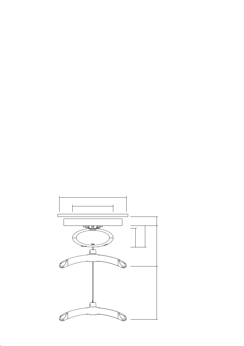
Dimensions
A ......................................................580 mm
B ......................................................350 mm
C (GH1 / GH1 Q) ..................................156 mm / 187 mm
D (GH1 / GH1 Q) ..................................184 mm / 196 mm
E, min ....................................................59 mm
F, min (GH1 / GH1 Q) ..............................415 mm / 427 mm
G .....................................................2500 mm
Depth of hoist ............................................194 mm
© Guldmann GB/US-1706/12/2016 • # 550865_14
B
E
C
27
F
D
Page 28

Safety
Emergency stop .............................................. Ye s
Emergency lowering device .............................Yes, electrical
Control of lifting strap .......................................... Yes
Cut-off angle ......................................45° along the rail
..............................................10° across the rail
Electronics
On/off ...........................Automatic when used. Soft start/stop
Overload protection ...................................... Automatic
Low battery protection .................................... Automatic
Power supply ...................................... 36 V DC, 0.83 A
Supply voltage, transformer .....................100-240 V AC, 47-63 Hz
Battery ............................................... 24 V NiMH
SWL: 175 kg (385 lbs), 205 kg (450 lbs), 255 kg (560 lbs) ...........2.0 Ah
Continuous operation with short time loading with
3 hours without recharging .......10/90 % (2 min. operation/18 min. pause)
Max number of lifts in series with:
85 kg (187 lbs) ........................................ 55/1000 mm
SWL: 175 kg (385 lbs), 205 kg (450 lbs), 255 kg (560 lbs) ......21/1000 mm
Max charging time at 25ºC (77ºF):
SWL: 175 kg (385 lbs), 205 kg (450 lbs), 255 kg (560 lbs) ..........3 hours
Operating temperature ....................... 10°C - 35°C (50°F - 95°F)
Degree of protection against harmful ingress of liquids (water)
Lifting module. . . . . . . . . . . . . . . . . . . . . . . . . . . . . . . . . . . . . . . . . . . . . . . IP 44
Hand control. . . . . . . . . . . . . . . . . . . . . . . . . . . . . . . . . . . . . . . . . . . . . . . . IP 44
Charging station .............................................IP 20
Power supply ...............................................IP 20
8.00 EC-Declaration of conformity
The products are manufactured in compliance with the Council Directive
93/42/EEC of 14 June 1993 – with amendments, as medical device class 1.
28
© Guldmann GB/US-1706/12/2016 • # 550865_14
Page 29

9.00 Environmental policy statement - V. Guldmann A/S
Guldmann is continuously working towards ensuring that the company’s
impact on the environment, locally and globally, is reduced to a minimum.
It is Guldmann’s goal to:
• Comply with the current environmental legislation (e.g. WEEE and REACH
directives)
• Ensure that we, at the widest possible range, use RoHS compliant materials
and components
• Ensure that our products do not have an unnecessary negative impact on the
environment regarding use, recirculation or disposal
• Ensure that our products contribute to a positive working environment in the
places they are utilised
Inspections are made annually by the Department for Nature and Environment from the Municipality of Aarhus using the Danish Environmental Protection Act, section 42 as a reference.
© Guldmann GB/US-1706/12/2016 • # 550865_14
29
Page 30

USA and countries outside the EU
A. Users guide
Before using the product, read the entire operation manual
including warranty.
B. WARRANTY
Guldmann warrants its equipment is free from material defects under normal
use, and will perform substantially in accordance with the specications set
forth in documentation provided with the equipment.
This express warranty shall be in effect for one year from the date of original
purchase and installation (the “Warranty Period”). If a valid claim is made
during the Warranty Period for malfunction or equipment defect, Guldmann will
repair or replace the equipment at no additional cost to you. Guldmann retains
sole discretion as to whether the equipment will be repaired or replaced.
This warranty shall be null and void if the equipment is operated and maintained in any manner inconsistent with its intended use or the instructions
provided with the product. Further, in order for the warranty to remain in effect
for the full Warranty Period, all service to the equipment must be provided
by a Guldmann designated technician. Any parts or components repaired or
replaced by a Guldmann designated technician will be guaranteed for the
remainder of the Warranty Period.
The warranty does not cover any part of the equipment which has been subject to damage or abuse by the user or others. The warranty does not cover
any part of the equipment which has been altered or changed in any way by
the user or others. Guldmann does not warrant that the lifting device functions
will meet your requirements, be uninterrupted or error free.
The warranty set forth is in lieu of all other express and implied warranties,
whether oral, written or implied, and the remedies set forth above are your
sole and exclusive remedies. Only an authorized ofcer of Guldmann may
make modications to this warranty, or additional warranties binding on Guld-
mann. Accordingly, additional statements such as advertising or presentations, whether oral or written, do not constitute warranties by Guldmann.
Service or Repair
Contact Guldmann Repair for an authorization to return any defective item
during the Warranty Period. You will be provided with a return authorization
number and address for returning the item for warranty service or replacement. Do not return items to Guldmann under warranty without receiving a
Return Authorization Number.
If mailing the item, pack it carefully in a sturdy carton to prevent damage. Include
your Return Authorization Number, a brief description of the problem and your
return address and phone number. Guldmann does not assume the risk of loss
or damage while in transit, so it is recommended you insure the package.
30
© Guldmann GB/US-1706/12/2016 • # 550865_14
Page 31

© Guldmann GB/US-1706/12/2016 • # 550865_14
31
Page 32
V. Guldmann A/S
Corporate Ofce:
Graham Bells Vej 21-23A
DK-8200 Aarhus N
Tel. +45 8741 3100
Fax +45 8741 3131
[email protected]
www.guldmann.com
Guldmann Inc.
14401 McCormick Drive,
Unit A
Tampa, FL 33626
Tel. 800 664 8834
Tel. 813 880 0619
Fax 813 880 9558
[email protected]
www.guldmann.net
© Guldmann GB/US-1706/12/2016 • # 550865_14
32
 Loading...