

GuitarPCB Mini-Me Instructions Manual
GuitarPCB.com
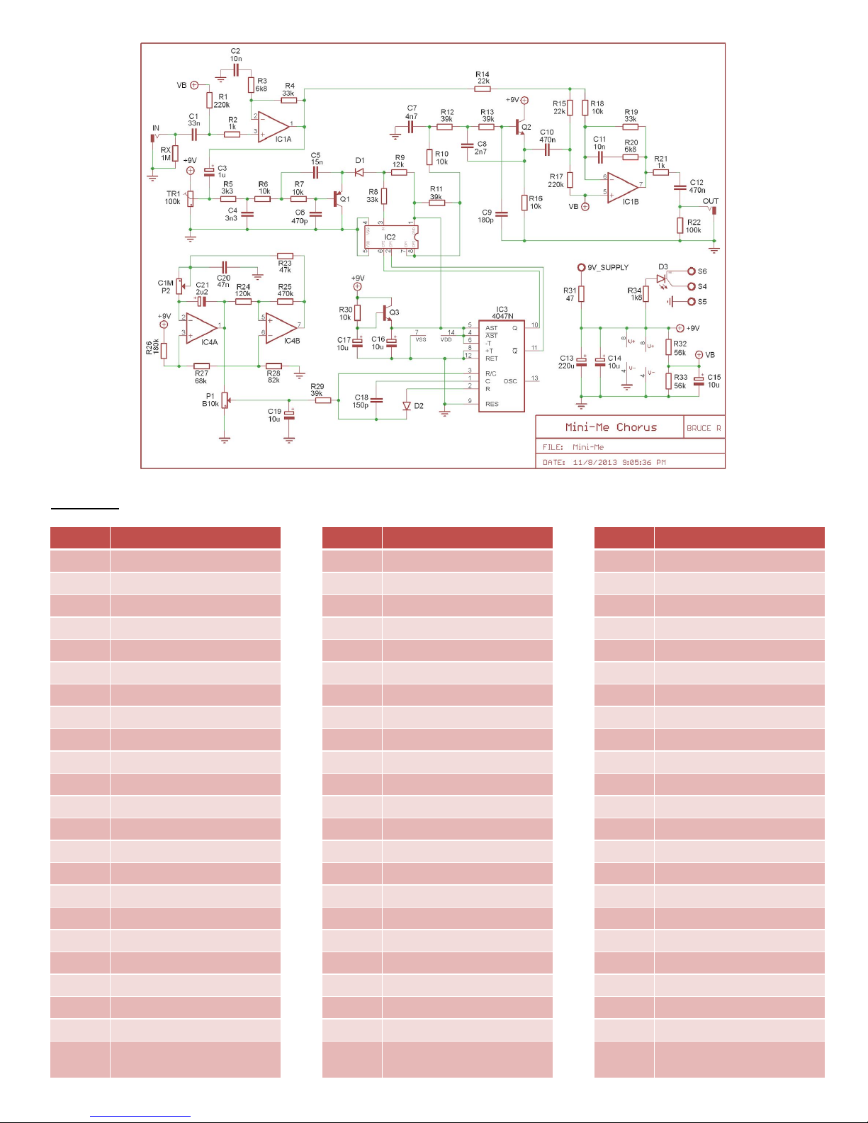
Mini-Me Chorus Build Instructions
This compares to the popular Small Clone
TM
chorus, but includes modifications. The major difference between this circuit and the
commercial pedal on which this is based is the addition of a depth knob, which provides more flexibility than the original commercial
pedal, which only had a depth selector switch. Even better the circuit is isolated into two parts, each separately grounded for the
sole purpose of noise free operation compared to similar offerings. This requires you to connect both ground pads labeled: GND and
G2.
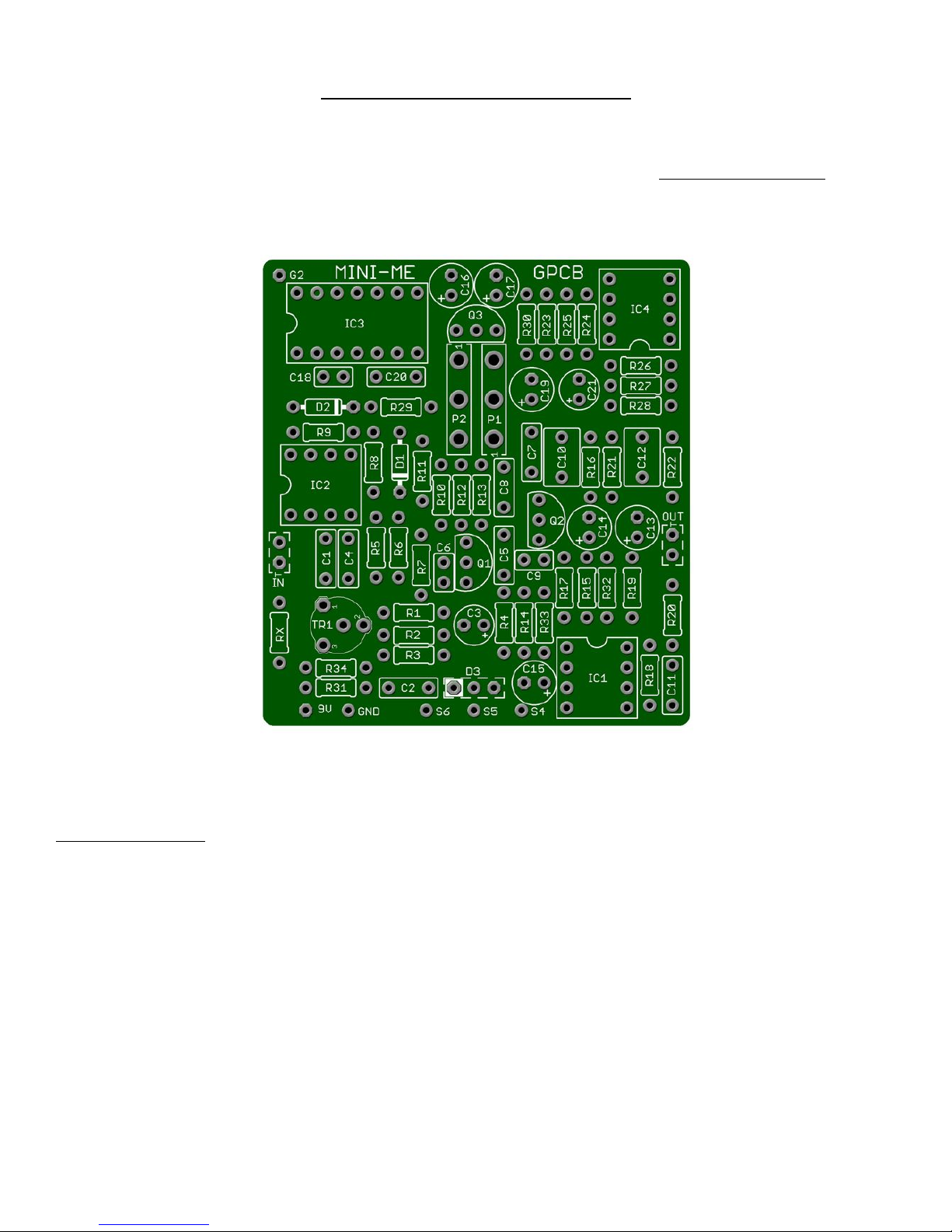
Board Dimensions (W x H) 2.08 x 2.32 inches, i.e.: 54 x 59mm. We recommend a 125B enclosure or larger for beginners.
IMPORTANT NOTES
● This board has 2 separate ground planes to prevent audible clock noise. Both ground planes need to be connected,
preferably to the main source ground (especially for G2). Please make sure that pads GND and G2 are both grounded.
● The MN3007 IC is no longer produced. eBay has many international sellers of these chips also. There has been some debate
over whether these IC’s are “genuine Motorola” or knock-offs. We recommend you purchase from Small Bear USA and
remind you that if you purchase from eBay, proceed (at your own risk) with caution as they are now heavily counterfeited..
GuitarPCB.com does not endorse any eBay or Asian sellers or make any guarantee that you’ll get working IC’s from them.
● Please note that the CoolAudio 3207 IC has slightly different voltage requirements and is incompatible with this board.
● This board has 16mm PCB-mounted potentiometers, which mount to the underside of the board. We highly recommend
that you mount the pots in your drilled enclosure, and then fit the board onto the pots, and solder them together.
Absolutely do not solder the pots to the board and then force the pots into the holes, or you may break the circuit board. If
you prefer, you may also use wired pots and arrange them knobs in your enclosure to suit your personal preferences.
● The trimmer potentiometer is for biasing the output of IC1A and should be adjusted by ear until the chorus effect is most
pronounced. On our builds, this was a little to the left of center.
PART LIST
Part
Value
Part
Value
Part
Value
D1
1n914
R21
1k
C3
1u
D2
1n914
R22
100k
C4
3n3
Rx
1M
R23
47k
C5
15n
R1
220k
R24
120k
C6
470p
R2
1k
R25
470k
C7
4n7
R3
6k8
R26
180k
C8
2n7
R4
33k
R27
68k
C9
180p
R5
3k3
R28
82k
C10
470n
R6
10k
R29
39k
C11
10n
R7
10k
R30
10k
C12
470n
R8
33k
R31
47 ohm
C13
220u
R9
12k
R32
56k
C14
10u
R10
10k
R33
56k
C15
10u
R11
39k
R34
1k8 (CLR)
C16
10u
R12
39k
IC1
4558
C17
10u
R13
39k
IC2
MN3007
C18
150p
R14
22k
IC3
CD4047
C19
10u
R15
22k
IC4
LM358N
C20
47n
R16
10k
Q1
2N5087
C21
2u2
R17
220k
Q2
2N5088
P1
DEPTH: B10k
R18
10k
Q3
2N5088
P2
RATE: C1M
R19
33k
C1
33n
TR1
100k (see text)
R20
6k8
C2
10n
D3
Bi-Color CA LED (see
text)
 Loading...