

Page 1

- USER MANUAL
- MANUEL DE L’UTILISATEUR
- BENUTZERHANDBUCH
- HANDLEIDING
- MANUALE D’USO
- MANUAL DEL USUARIO
- MANUAL DO UTILIZADOR
РУКОВОДСТВО ПОЛЬЗОВАТЕЛЯ
ΕΓΧΕΙΡΙΙΟ ΧΡΗΣΗΣ
KULLANIM KILAVUZU
INSTRUKCJA OBSŁUGI
Page 2
1/17
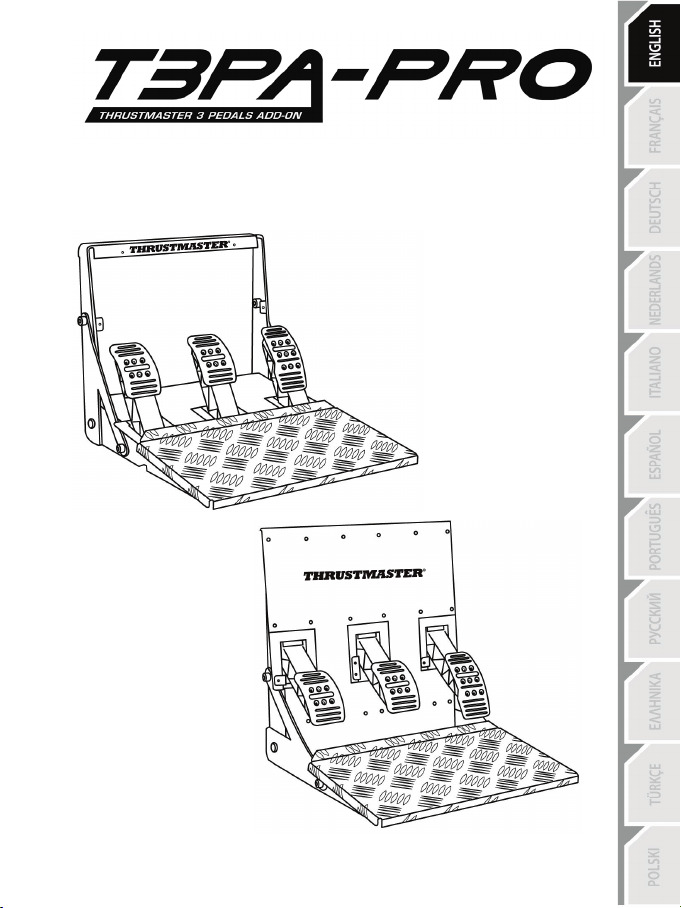
For: PC – PlayStation®3 – PlayStation®4 – Xbox One®
User Manual
Page 3

2/17
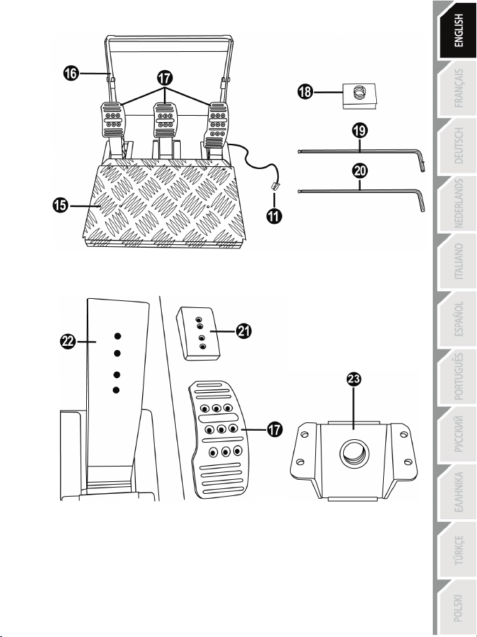
TECHNICAL FEATURES
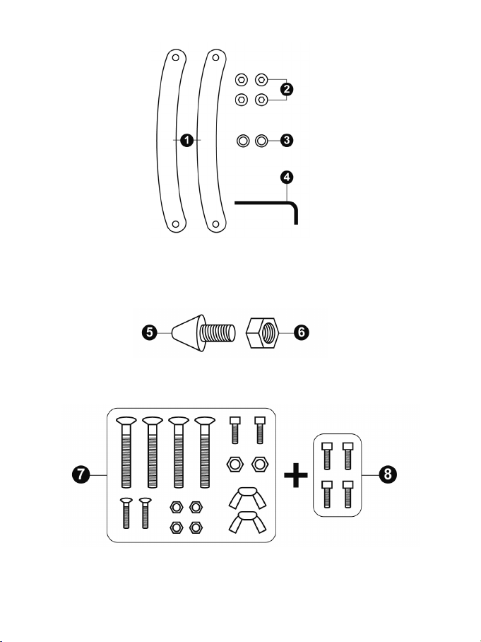
1 2 lateral arches (left and right)
3 2 plastic washers
(to attach the lateral arches)
5 Removable CONICAL RUBBER BRAKE MOD
6 Fastening and adjustment nut
MOD)
7 Backup
8 4 M3-type Allen screws
2 4 M8-type Allen screws
(to attach the lateral arches)
(various extra screws and nuts)
(to attach the lateral arches)
4 6 mm Allen key
(to attach the CONICAL RUBBER BRAKE
(to attach the removable metal stop)
Page 4
3/17
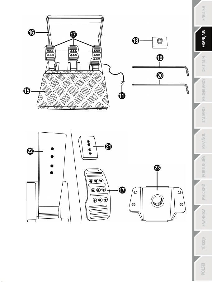
11 Pedal set cable and connector
17 Removable pedal heads
18 Removable SPRING BRAKE MOD
20 Included 2.5 mm Allen key
17 Metal head
22 Metal pedal arm
(not installed by default)
15 Removable foot rest
16 Lateral arches when installed
(not installed by default)
19 Included 2 mm Allen key
21 Plastic head support
23 Removable metal stop
Page 5
4/17
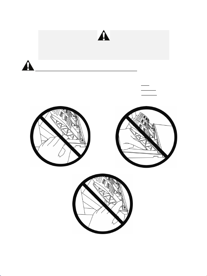
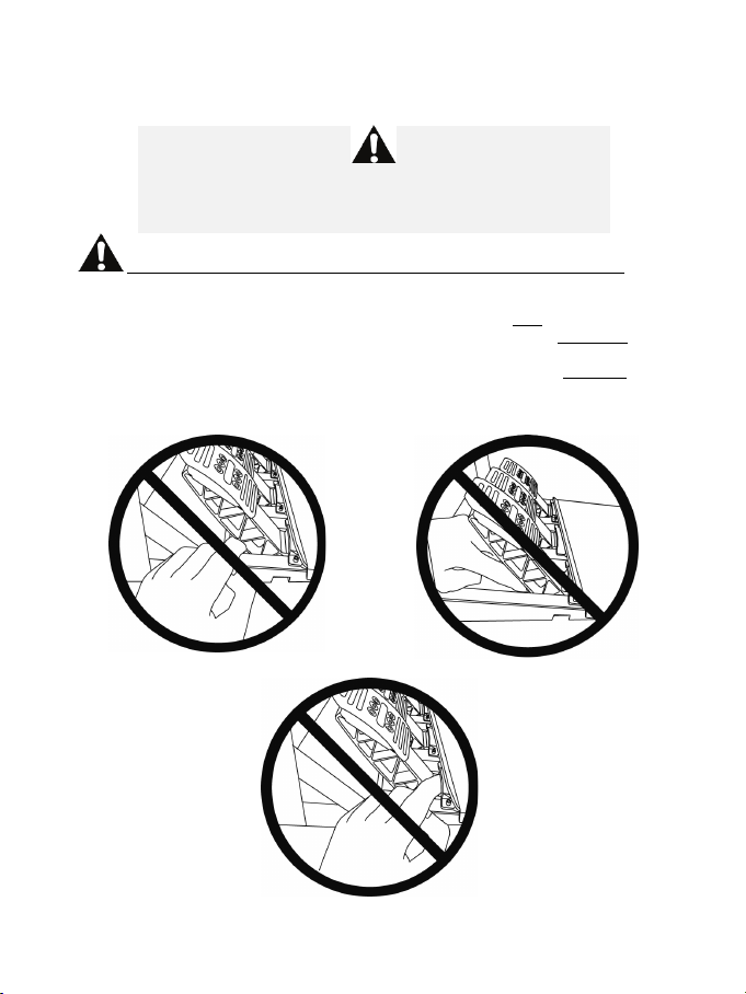
WARNING
NEVER
NEVER
NEVER
Before using this product, be sure to read these instructions carefully and save them for future reference.
For safety reasons, never use the pedal set with bare feet or while wearing
THRUSTMASTER® DISCLAIMS ALL RESPONSIBILITY IN THE EVENT OF
INJURY RESULTING FROM USE OF THE PEDAL SET WITHOUT SHOES.
Warning – Pedal set pinching hazard during gaming sessions
* Keep the pedal set out of the reach of children.
* During gaming sessions, never place your fingers or thumbs on or near the sides of the pedals.
* During gaming sessions, never place your fingers or thumbs on or near the rear base of the pedals.
* During gaming sessions, never place your fingers or thumbs on or near the front base of the pedals.
only socks on your feet.
Page 6
5/17
yourself or on anyone else!
AUTOMATIC CALIBRATION OF PEDALS
- Never connect or disconnect the pedal set from the base of the wheel when the wheel is
connected to the console or PC, or during gaming sessions, to avoid calibration problems.
= Always connect the pedal set to the wheel before connecting the wheel to the console or PC.
- Once the wheel has self-calibrated and the game has started, the pedals automatically calibrate
themselves after being pressed a few times.
- Never press on the pedals when the wheel is self-calibrating or when your game is starting up, to
avoid calibration problems.
- If the pedals are not functioning correctly or appear to be improperly calibrated, power off your
console, completely disconnect your wheel, then reconnect all of the cables (including the power
supply cable and the pedal set cable), power the console back on and restart your game.
IMPORTANT:
ATTACHING THE PEDAL SET TO A COCKPIT
- Attach the pedal set using the small screw threads located on the underside of the pedal set.
- Screw M6 screws (not included) into the cockpit’s pedal support plate and into the small screw
threads located on the underside of the pedal set.
Important: The length of the M6 screws must not exceed the thickness of the cockpit’s pedal
support plate plus an additional 10 mm, to avoid damaging the pedal set’s internal components.
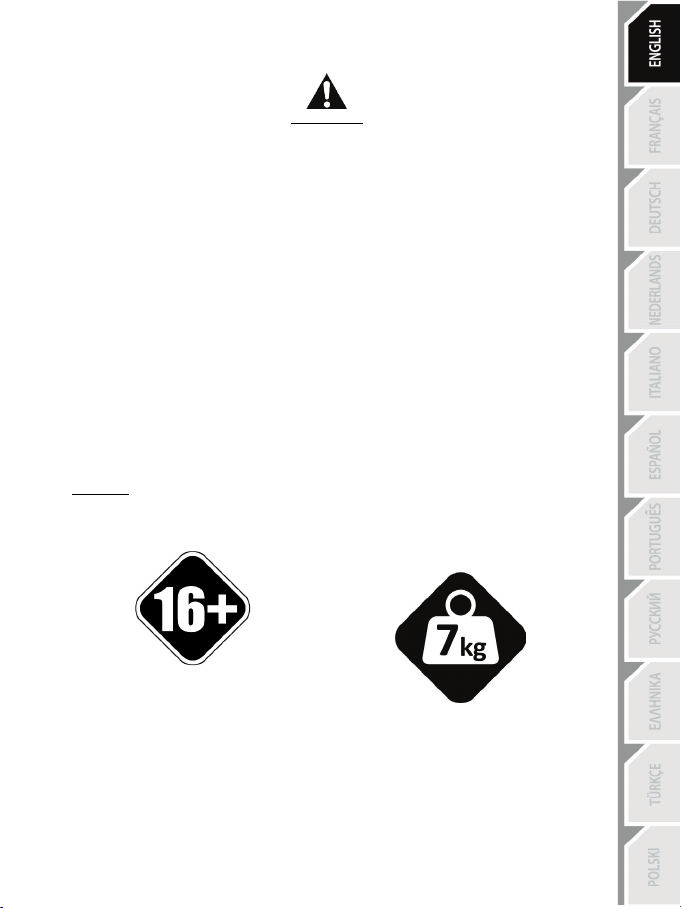
HEAVY PRODUCT
To be handled only by users
16 years of age or older
Be careful not to drop the product on
Page 7

6/17
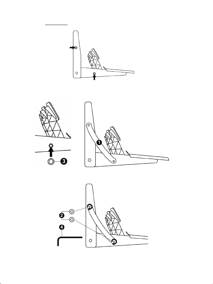
INSTALLING THE 2 LATERAL ARCHES (1)
Positions of the pedal set’s 2 lateral screw threads (1 upper + 1 lower) in order to attach the 2 lateral
arches (1):
- Place one of the plastic washers (3) on the screw thread located on the lower part of the pedal set.
- Next, place one of the arches (1) on the screw thread located on the upper part of the pedal set
and on the plastic washer (3).
- Attach the arch (1) using 2 of the M8-type Allen screws (2) and the 6 mm Allen key (4) by turning
the screws clockwise.
- Repeat this procedure on the other side of the pedal set to attach the second arch.
You are now ready to play!
Page 8
7/17
Low position
Medium position (default)
High position
Very high position
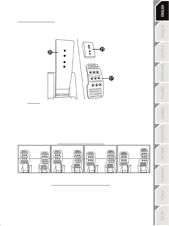
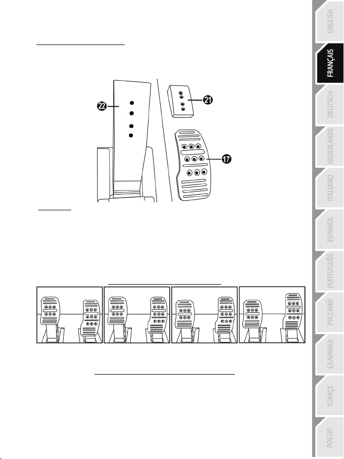
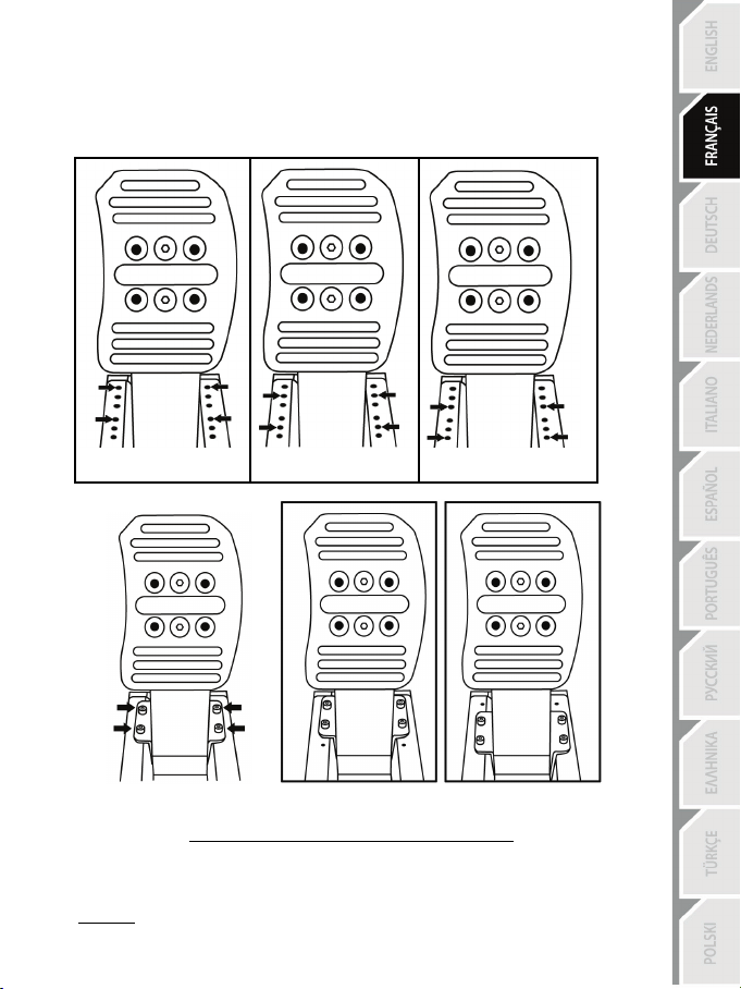
CONFIGURING THE PEDALS
Each of the 3 pedals features:
- A metal head (17) with several perforations
(9 for the accelerator – 6 for the brake – 6 for the clutch)
- A plastic head support (21) (between the head and the arm) with 4 perforations
- A metal pedal arm (22) with 4 perforations
Adjusting the pedal HEIGHT
- Using the included 2.5 mm Allen key (20), loosen and remove the 2 screws holding the metal
head (17) and its support (21) in place.
- Once this is done, select the height of your choice and then replace and re-tighten the screws.
CAUTION: To avoid any calibration problems, always disconnect the USB cable
from your steering wheel before adjusting the settings on your pedal set.
Examples with the accelerator pedal:
Number of possible height positions per pedal:
- 4 for the accelerator pedal
- 2 for the brake pedal
- 2 for the clutch pedal
Page 9
8/17
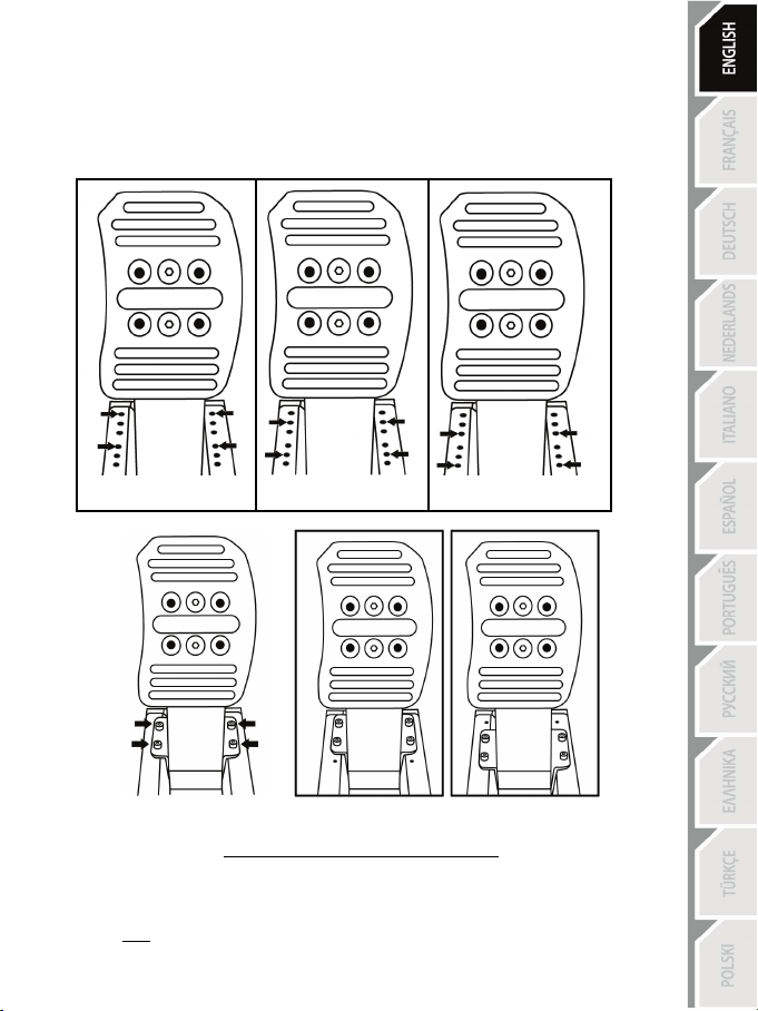
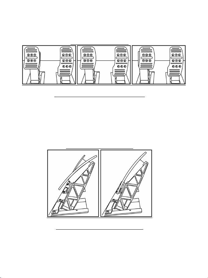
Adjusting the pedal SPACING
- Using the included 2.5 mm Allen key (20), loosen and remove the 2 screws holding the metal
head (17) and its support (21) in place.
- Once this is done, select the position of your choice (to the left, in the center or to the right) and
then replace and re-tighten the screws.
Examples with the brake pedal:
Left position Center position (default) Right position
Number of possible spacing positions per pedal:
- 3 for the accelerator pedal
- 3 for the brake pedal
- 3 for the clutch pedal
Adjusting the pedal TILT
- Using the included 2.5 mm Allen key (20), loosen and remove the 2 screws holding the metal
head (17) and its support (21) in place.
- Once this is done, turn the plastic head support (21) 180°, and then replace and re-tighten the
screws.
Examples with the accelerator pedal:
Less tilted position More tilted position (default)
Number of possible tilt positions per pedal:
- 2 for the accelerator pedal
- 2 for the brake pedal
- 2 for the clutch pedal
Page 10
9/17
Adjusting the range of TRAVEL and resistance FORCE of the brake pedal (with
no BRAKE MOD installed)
- Install the metal stop (23) at the rear of the brake pedal arm.
- Select your choice of position (Long, Medium or Short range of travel), and then tighten the 4 M3type Allen screws (8) using the included 2.5 mm Allen key (20).
Long travel and strong Medium travel and Short travel and
resistance (default) medium resistance weak resistance
Long travel and strong Short travel and
resistance (default) weak resistance
Number of possible travel or resistance positions:
- Long travel with resistance of approximately 22 lbs / 10 kg
- Medium travel with resistance of approximately 18.7 lbs / 8.5 kg
- Short travel with resistance of approximately 15.4 lbs / 7 kg
Note: the longer the travel, the stronger the pedal’s resistance (and vice versa).
Page 11
10/17
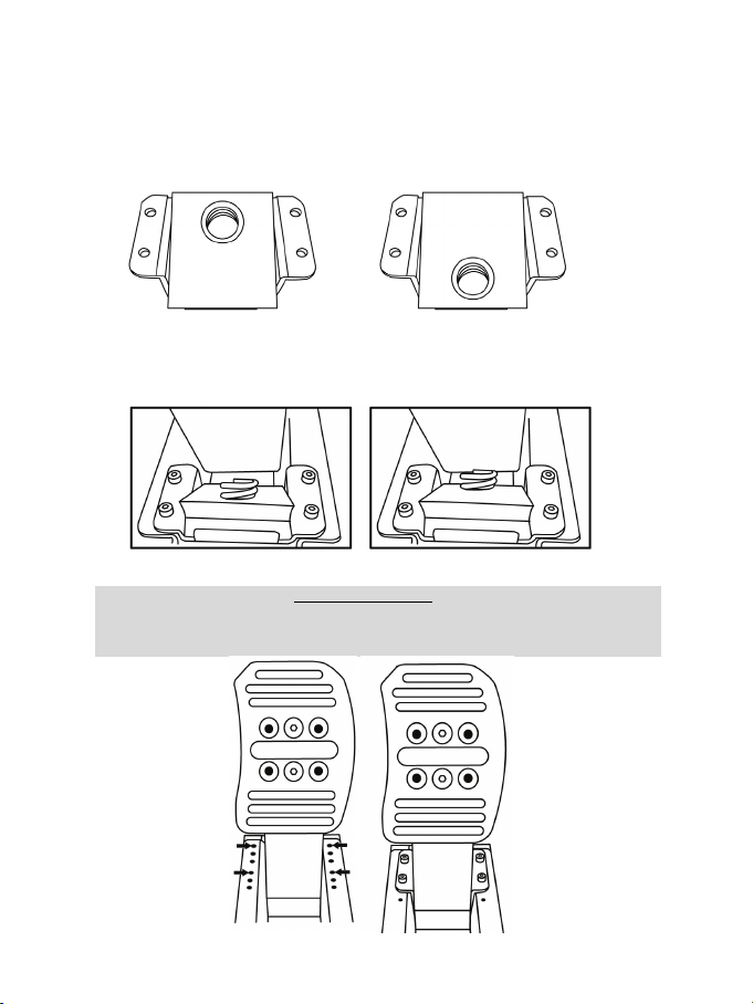
Installing the SPRING BRAKE MOD (18)
Important note:
(i.e. do not install it in the Medium range or Short range of travel positions)
This mod allows for different sensations and resistance when braking.
Users must decide whether or not to install it according to their own preferences.
- Install the SPRING BRAKE MOD (18) fully and tightly into the bottom of the cavity in the metal
stop (23).
- For strong resistance: position the mod against the upper wall.
- For even stronger resistance: position the mod against the lower wall.
Position against the upper wall Position against the lower wall
(resistance of approx. 30.9 lbs / 14 kg) (resistance of approx. 35.2 lbs / 16 kg)
- Once this is done, attach the metal stop (23) behind the pedal’s arm with the 4 M3-type Allen
screws (8), using the included 2.5 mm Allen key (20).
Position against the upper wall Position against the lower wall
(resistance of approx. 30.9 lbs / 14 kg) (resistance of approx. 35.2 lbs / 16 kg)
To avoid any calibration problems, the SPRING BRAKE MOD must only be installed
in the Long range of travel position
Page 12
11/17
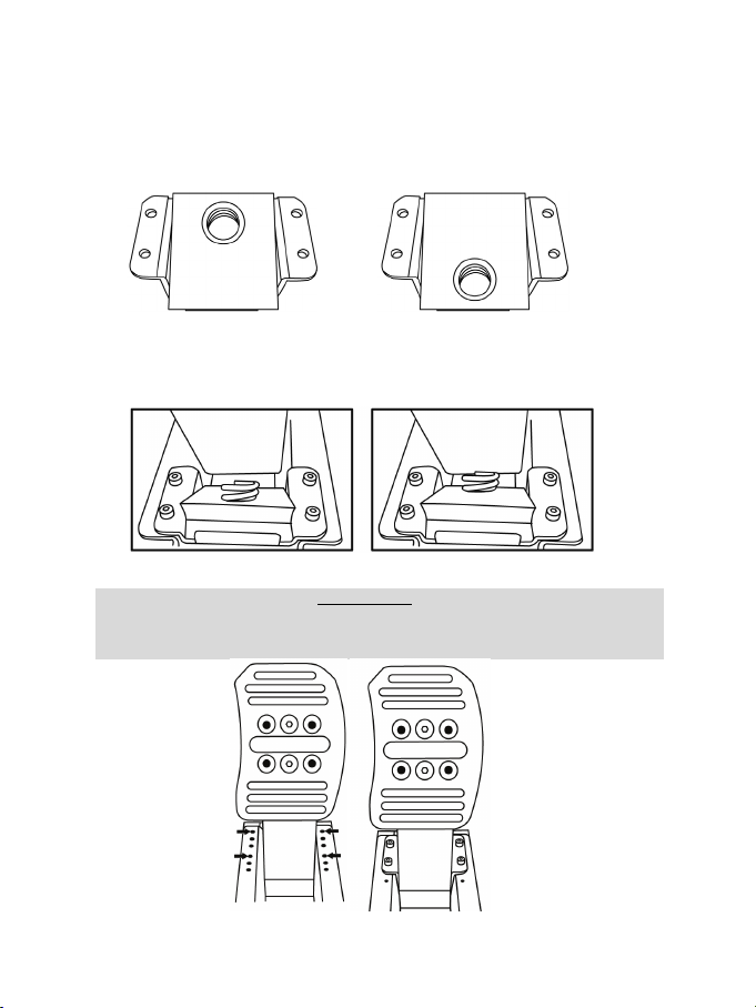
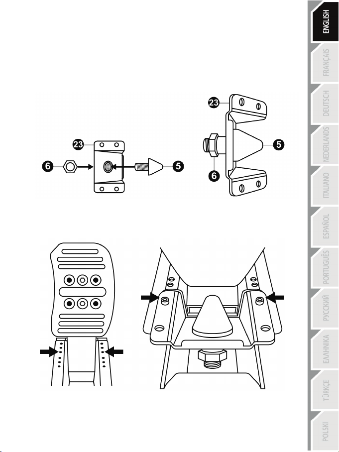
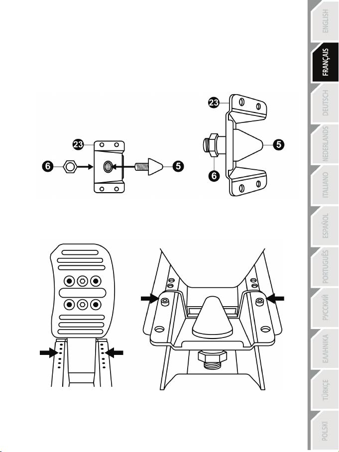
Installing the CONICAL RUBBER BRAKE MOD (5)
This mod provides you with an authentic feel when braking, and ultra-progressive resistance at the
end of the pedal’s range of travel.
Users must decide whether or not to install it according to their own preferences.
- Screw the CONICAL RUBBER BRAKE MOD (5) into the screw thread in the metal stop (23), then
tighten the fastening and adjustment nut (6) on the back, onto the protruding screw of the
CONICAL RUBBER BRAKE MOD.
- Next, attach the metal stop (23) behind the pedal’s arm using only 2 M3-type Allen screws (8)
(i.e. not using 4 screws), in the position shown in the diagrams below
= in the Very long range of travel position
(Be sure to follow this point exactly, to avoid any calibration problems!)
Once installed in this position (the Very long range of travel position), the metal stop slightly
overlaps the large black piece of metal sheet behind the pedals, and is attached with only 2
Allen screws: this is perfectly normal.
Page 13

12/17
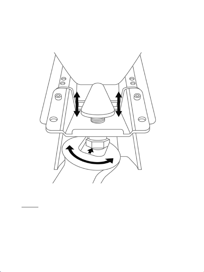
Adjusting the range of TRAVEL and resistance FORCE of the brake pedal with
the CONICAL RUBBER BRAKE MOD (5) installed
- Using a 14 mm open-end wrench (not included), slightly loosen the fastening and adjustment nut
(6).
- Depending on your preference, move the CONICAL RUBBER BRAKE MOD (5) a bit closer to or
farther away from the back of the brake pedal.
- Once you have selected the position, simply re-tighten the fastening and adjustment nut (6) using
the 14 mm open-end wrench.
Depending on the position you have selected, the resistance of the CONICAL RUBBER
BRAKE MOD will be between 44 lbs / 20 kg (when the mod is farther away from the pedal)
and 66 lbs / 30 kg (wh en the mod is closer to the pedal).
Please note: If the CONICAL RUBBER BRAKE MOD is too close to the back of the brake pedal’s
arm, it may happen that the pedal’s values do not completely return to zero when you release the
pedal very lightly.
If that is the case:
* In the options of the game you are playing, add a small dead zone at the start of the brake pedal’s
range of travel; or
* Move the CONICAL RUBBER BRAKE MOD a bit farther away from the back of the brake pedal’s
arm.
Page 14
13/17
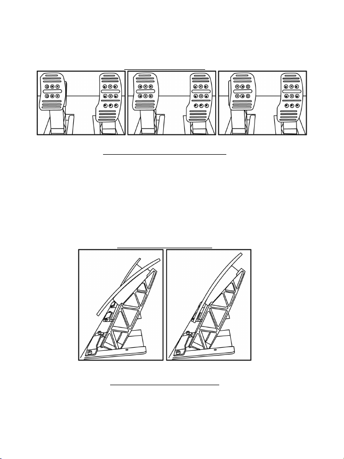
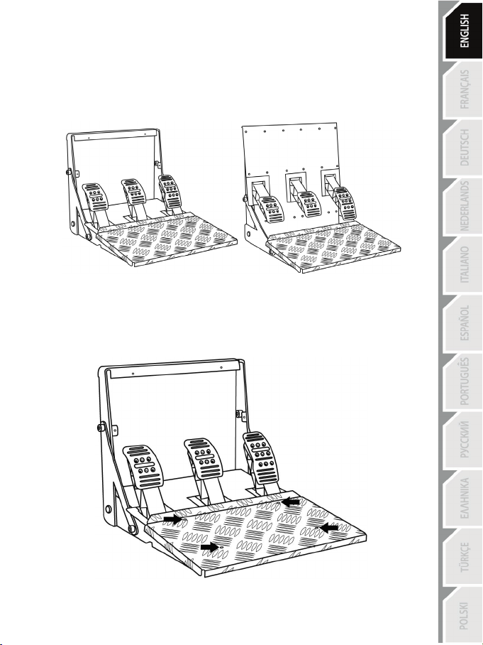
INVERTING THE PEDAL SET’S POSITION
The T3PA-PRO pedal set has a unique design (patent pending) allowing for your choice of 2
different positions:
- Floor-mounted position (F1-style)
- Suspended position (GT/Rally-style)
By default, the pedal set comes in the floor-mounted position (F1-style).
Floor-mounted position (F1-style) Suspended position (GT/Rally-style)
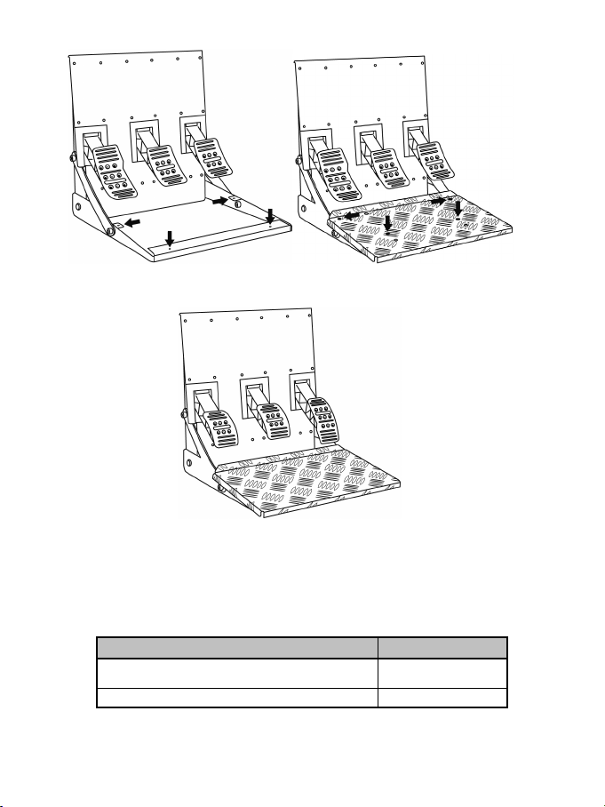
PHYSICALLY INVERTING the pedal set
- Using the included 2 mm Allen key (19), unscrew the 4 screws holding the removable foot rest
(15) in place.
Page 15
14/17
- Turn the pedal set 180°, then replace and retighten the screws in the 4 screw threads located on
PEDAL SET POSITION
LED COLOR
FLOOR-MOUNTED (F1-style)
(by default)
SUSPENDED (GT/Rally-style)
GREEN
the arch (16) .
- Using the included 2.5 mm Allen key (20), unscrew the 3 metal heads (17) to turn them over 180°,
and swap the positions of the accelerator head and the clutch head.
You are now ready to play!
ELECTRONICALLY SWAPPING the accelerator and clutch pedals
When you physically invert the pedal set’s position, simply press the MODE button (located on the
base of your wheel) to swap the accelerator and clutch pedals electronically (the LED color indicates
the position you have selected).
RED
The selected position is then immediately stored in the wheel’s internal memory.
Page 16

15/17
Consumer warranty information
Worldwide, Guillemot Corporation S.A. (hereinafter “Guillemot”) warrants to the consumer that this
Thrustmaster product shall be free from defects in materials and workmanship, for a warranty period
which corresponds to the time limit to bring an action for conformity with respect to this product. In
the countries of the European Union, this corresponds to a period of two (2) years from delivery of
the Thrustmaster product. In other countries, the warranty period corresponds to the time limit to
bring an action for conformity with respect to the Thrustmaster product according to applicable laws
of the country in which the consumer was domiciled on the date of purchase of the Thrustmaster
product (if no such action exists in the corresponding country, then the warranty period shall be one
(1) year from the original date of purchase of the Thrustmaster product).
Notwithstanding the above, rechargeable batteries are covered by a warranty period of six (6)
months from the date of original purchase.
Should the product appear to be defective during the warranty period, immediately contact Technical
Support, who will indicate the procedure to follow. If the defect is confirmed, the product must be
returned to its place of purchase (or any other location indicated by Technical Support).
Within the context of this warranty, the consumer’s defective product shall, at Technical Support’s
option, be either repaired or replaced. If permitted under applicable law, the full liability of Guillemot
and its subsidiaries (including for consequential damages) is limited to the repair or replacement of
the Thrustmaster product. If permitted under applicable law, Guillemot disclaims all warranties of
merchantability or fitness for a particular purpose. The consumer’s legal rights with respect to laws
applicable to the sale of consumer goods are not affected by this warranty.
This warranty shall not apply: (1) if the product has been modified, opened, altered, or has suffered
damage as a result of inappropriate or abusive use, negligence, an accident, normal wear, or any
other cause unrelated to a material or manufacturing defect (including, but not limited to, combining
the Thrustmaster product with any unsuitable element, including in particular power supplies,
rechargeable batteries, chargers, or any other elements not supplied by Guillemot for this product);
(2) in the event of failure to comply with the instructions provided by Technical Support; (3) to
software, said software being subject to a specific warranty; (4) to consumables (elements to be
replaced over the product’s lifespan: disposable batteries, audio headset or headphone ear pads, for
example); (5) to accessories (cables, cases, pouches, bags, wrist-straps, for example); (6) if the
product was sold at public auction.
This warranty is nontransferable.
Additional warranty provisions
In the United States of America and in Canada, this warranty is limited to the product’s internal
mechanism and external housing. In no event shall Guillemot or its affiliates be held liable to any
third party for any consequential or incidental damages resulting from the breach of any express or
implied warranties. Some States/Provinces do not allow limitation on how long an implied warranty
lasts or exclusion or limitation of liability for consequential or incidental damages, so the above
limitations or exclusions may not apply to you. This warranty gives you specific legal rights, and you
may also have other rights which vary from State to State or Province to Province.
Page 17
16/17
Liability
If permitted under applicable law, Guillemot Corporation S.A. (hereinafter “Guillemot”) and its
subsidiaries disclaim all liability for any damages caused by one or more of the following: (1) the
product has been modified, opened or altered; (2) failure to comply with assembly instructions; (3)
inappropriate or abusive use, negligence, an accident (an impact, for example); (4) normal wear. If
permitted under applicable law, Guillemot and its subsidiaries disclaim all liability for any damages
unrelated to a material or manufacturing defect with respect to the product (including, but not limited
to, any damages caused directly or indirectly by any software, or by combining the Thrustmaster
product with any unsuitable element, including in particular power supplies, rechargeable batteries,
chargers, or any other elements not supplied by Guillemot for this product).
FCC STATEMENT
1. This device complies with Part 15 of the FCC Rules. Operation is subject to the following two
conditions:
(1) This device may not cause harmful interference, and
(2) This device must accept any interference received, including interference that may cause
undesired operation.
2. Changes or modifications not expressly approved by the party responsible for compliance could
void the user's authority to operate the equipment.
COPYRIGHT
© 2015 Guillemot Corporation S.A. All rights reserved. Thrustmaster
Guillemot Corporation S.A. “
trademarks of Sony Computer Entertainment, Inc. “
”, “PlayStation”, “ ” and “ ” are registered
®
is a registered trademark of
” is a trademark of the same company.
Xbox is a registered trademark of Microsoft Corporation in the United States and/or in other
countries. All other trademarks and brand names are hereby acknowledged and are the property of
their respective owners. Illustrations not binding. Contents, designs and specifications are subject to
change without notice and may vary from one country to another. Made in China.
ENVIRONMENTAL PROTECTION RECOMMENDATION
At the end of its working life, this product should not be disposed of with standard
household waste, but rather dropped off at a collection point for the disposal of
Waste Electrical and Electronic Equipment (WEEE) for recycling.
This is confirmed by the symbol found on the product, user manual or packagi ng.
Depending on their characteristics, the materials may be recycled. Through
recycling and other forms of processing Waste Electrical and Electronic Equipment,
you can make a significant contribution towards helping to protect the environment.
Please contact your local authorities for inf ormation on the c ollection point nearest you.
Retain this information. Colors and decorations may vary.
This product conforms to all standards regarding children 16 years of age and older. This product is
not suitable for use by children less than 16 years of age.
www.thrustmaster.com
Page 18

17/17
TECHNICAL SUPPORT
http://ts.thrustmaster.com
Page 19
1/17
Pour : PC – PlayStation®3 – PlayStation®4 – Xbox One®
Manuel de l’utilisateur
Page 20
2/17
CARACTERISTIQUES TECHNIQUES
1 2 arceaux latéraux (gauche et droite)
3 2 rondelles en plastique
(pour fixer les arceaux latéraux)
5 CONICAL RUBBER BRAKE MOD amovible
6 Écrou de fixation et de réglage
MOD)
7 Backup
8 4 vis Allen type M3
2 4 vis Allen type M8
(pour fixer les arceaux latéraux)
(divers vis et écrous fournis en supplément)
(pour fixer les arceaux latéraux)
4 Clé Allen 6 mm
(pour fixer le CONICAL RUBBER BRAKE
(pour fixer la butée métallique amovible)
Page 21
3/17
11 Câble et connecteur du pédalier
17 Tête des pédales amovible
18 SPRING BRAKE MOD amovible
20 Clé Allen 2,5 mm fournie
17 Tête métallique
22 Bras métallique
(non installée par défaut)
15 Repose-pieds amovible
16 Arceaux latéraux une fois installés
(non installé par défaut)
19 Clé Allen 2 mm fournie
21 Support de tête plastique
23 Butée métallique amovible
Page 22
4/17
AVERTISSEMENT
JAMAIS
JAMAIS
JAMAIS
Avant d’utiliser ce produit, lisez attentivement cette documentation et conservez-la pour pouvoir la
consulter ultérieurement.
Pour des raisons de sécurité, ne jouez pas pieds nus ou en chaussettes
THRUSTMASTER® DECLINE TOUTE RESPONSABILITE EN CAS DE
BLESSURE SUITE A UNE UTILISATION DU PEDALIER SANS CHAUSSURES.
Avertissement – Risque de pincement au niveau du pédalier lors des phases de jeu
* Laissez le pédalier hors de portée des enfants.
* Lors des phases de jeu, ne placez jamais vos doigts sur ou à proximité des côtés des pédales.
* Lors des phases de jeu, ne placez jamais vos doigts sur ou à proximité de la base arrière des
pédales.
* Lors des phases de jeu, ne placez jamais vos doigts sur ou à proximité de la base avant des
pédales.
lorsque vous utilisez le pédalier.
Page 23
5/17
une autre personne !
CALIBRAGE AUTOMATIQUE DES PEDALES
- Ne branchez ou débranchez jamais le pédalier de la base du volant lorsque celui-ci est connecté à
la console ou au PC, ou en cours de jeu, pour ne pas fausser la calibration.
= Branchez toujours le pédalier avant de relier le volant à la console ou au PC.
- Une fois le volant autocalibré et le jeu lancé, les pédales se calibrent automatiquement après
quelques pressions.
- Lors des phases d’autocalibration de la roue du volant et lorsque votre jeu se lance, n’appuyez
jamais sur les pédales, au risque de fausser la calibration.
- Si vos pédales ne fonctionnent pas correctement ou semblent mal calibrées, éteignez votre
console, déconnectez entièrement votre volant, reconnectez tous les câbles (y compris le câble
d’alimentation secteur et le câble du pédalier), redémarrez la console et relancez votre jeu.
IMPORTANT :
FIXATION DU PEDALIER SUR UN COCKPIT
- Fixez le pédalier via les petits pas de vis situés sous ce dernier.
- Vissez des vis M6 (non fournies) dans la tablette du cockpit et dans les petits pas de vis situés
sous le pédalier.
Important : La longueur de ces vis M6 ne doit pas dépasser l’épaisseur de votre support +10 mm
pour ne pas endommager les composants internes du pédalier.
PRODUIT LOURD
Produit à manipuler uniquement par des
personnes âgées de 16 ans ou plus.
Ne pas laisser tomber le produit sur vous ou
Page 24
6/17
INSTALLATION DES 2 ARCEAUX LATERAUX (1)
Position des 2 pas de vis latéraux du pédalier (1 en haut + 1 en bas) pour venir fixer les
arceaux (1) :
- Positionnez l’une des rondelles en plastique ( 3) sur le pas de vis situé en bas du pédalier.
- Positionnez ensuite l’un des arceaux (1) sur le pas de vis situé en haut du pédalier et sur la
rondelle en plastique (3).
- Fixer l’arceau (1) à l’aide des 2 vis Allen type M8 (2) et de la clé Allen 6 mm (4) en tournant dans
le sens des aiguille d’une montre.
- Effectuez la même opération de l’autre côté du pédalier pour fixer le 2
Vous êtes maintenant prêt à jouer !
ème
arceau.
Page 25
7/17
Position Basse
Position Moyenne
(par défaut)
Position Haute
Position Très Haute
REGLAGES DU PEDALIER
Chacune des 3 pédales comprend :
- Une tête métallique (17) avec plusieurs perforations
(9 pour l’accélérateur – 6 pour le frein – 6 pour l’embrayage)
- Un support de tête plastique (21) (situé entre la tête et le bras) avec 4 perforations
- Un bras métallique (22) avec 4 perforations
Ajuster la HAUTEUR des pédales
- A l’aide de la clé Allen 2,5 mm fournie (20), dévissez les 2 vis maintenant la tête métallique (17) et
- Choisissez ensuite votre position en hauteur, puis revissez le tout.
ATTENTION : Pour éviter tout problème de calibration, débranchez toujours le câble USB de
son support (21).
votre volant avant d’ajuster votre pédalier.
Exemples ici avec la pédale d’accélérateur :
Nombre de positions en hauteur possibles par pédale :
- 4 pour la pédale d’accélérateur
- 2 pour la pédale de frein
- 2 pour la pédale d’embrayage
Page 26
8/17
Ajuster l’ÉCARTEMENT des pédales
- A l’aide de la clé Allen 2,5 mm fournie (20), dévissez les 2 vis maintenant la tête métallique (17) et
son support (21).
- Choisissez ensuite votre position (à gauche, au centre ou à droite), puis revissez le tout.
Exemples ici avec la pédale de frein :
Position à gauche Position au centre (par défaut) Position à droite
Nombre de positions en écartement possibles par pédale :
- 3 pour la pédale d’accélérateur
- 3 pour la pédale de frein
- 3 pour la pédale d’embrayage
Ajuster l’INCLINAISON des pédales
- A l’aide de la clé Allen 2,5 mm fournie (20), dévissez les 2 vis maintenant la tête métallique (17) et
son support (21).
- Retournez ensuite le support de tête plastique (21) de 180°, puis revissez le tout.
Exemples ici avec la pédale d’accélérateur:
Position moins inclinée Position plus inclinée (par défaut)
Nombre de positions d’inclinaison possibles par pédale :
- 2 pour la pédale d’accélérateur
- 2 pour la pédale de frein
- 2 pour la pédale d’embrayage
Page 27
9/17
Ajuster la COURSE de débattement et la FORCE de résistance de la pédale de
frein (sans BRAKE MOD installé)
- Installez la butée métallique (23) derrière le bras de la pédale de frein.
- Sélectionnez votre position (course Longue, Moyenne ou Courte), puis serrez les 4 vis Allen type
M3 (8) à l’aide de la clé Allen 2,5 mm fournie (20).
Position course Longue Position course Moyenne Position course Courte
et forte résistance (par défaut) et moyenne résistance et faible résistance
Position course Longue Position course Courte
et forte résistance (par défaut) et faible résistance
Nombre de positions de course ou de résistance possibles :
- Course Longue avec résistance d’environ 10 kg
- Course Moyenne avec résistance d’environ 8,5 kg
- Course Courte avec résistance d’environ 7 kg
Remarque : Plus la course est longue, plus la résistance de la pédale est forte (et inversement).
Page 28
10/17
Installer le SPRING BRAKE MOD (18)
Remarque importante :
(= ne pas installer en position course Moyenne ou course Courte )
Ce MOD permet d’apporter un feeling et une résistance différents lors des freinages.
Il appartiendra à chacun de l’installer ou non en fonction de ses préférences.
- Installez le SPRING BRAKE MOD (18) complètement et parfaitement au fond de la cavité de la
butée métallique (23).
- Pour une résistance forte : positionnez le MOD contre la paroi supérieure.
- Pour une résistance encore plus forte : positionnez le MOD contre la paroi inférieure.
Position contre la paroi supérieure Position contre la paroi inférieure
(résistance d’environ 14 kg) (résistance d’environ 16 kg)
- Vissez ensuite la Butée métallique ( 23) à l’arrière du bras de la pédale avec les 4 vis Allen type
M3 (8) à l’aide de la clé Allen 2,5 mm fournie (20).
Position contre la paroi supérieure Position contre la paroi inférieure
(résistance d’environ 14 kg) (résistance d’environ 16 kg)
Pour éviter tout problème de calibration, le SPRING BRAKE MOD ne doit être installé
qu’en position de débattement course Longue
Page 29
11/17
Installer le CONICAL RUBBER BRAKE MOD (5)
Ce MOD permet d’apporter, lors des freinages, un feeling authentique et une résistance ultra
progressive en fin de course.
Il appartiendra à chacun de l’installer ou non en fonction de ses préférences.
- Vissez le CONICAL RUBBER BRAKE MOD (5) dans le pas de vis de la butée métallique (23),
puis vissez l’écrou de fixation et de réglage (6) à l’arrière sur la vis dépassant du CONICAL
RUBBER BRAKE MOD.
- Vissez ensuite la butée métallique (23) à l’arrière du bras de la pédale avec uniquement 2 vis
Allen (et non 4) type M3 (8) dans la position indiquée sur les schémas ci-dessous
= en Position Course Très Longue
(Point à respecter impérativement pour éviter tout problème de calibration !)
Une fois installée dans cette position (en Course Très Longue), la butée métallique
chevauche légèrement la grande plaque de taule métallique noire arrière du pédalier et n’est
fixée qu’avec 2 vis Allen = ceci est tout à fait normal.
Page 30
12/17
Ajuster la COURSE de débattement et la FORCE de résistance de la pédale de
frein avec le CONICAL RUBBER BRAKE MOD (5) installé
- A l’aide d’une clé plate 14 mm (non fournie), dévissez légèrement l’écrou de fixation et de
réglage (6).
- Rapprochez ou éloignez (à votre convenance) le CONICAL RUBBER BRAKE MOD (5) de
l’arrière du bas de la pédale.
- Une fois la position choisie, resserrez simplement l’écrou de fixation et de réglage (6) à l’aide de
la clé plate 14 mm.
En fonction de la position choisie, la résistance avec le CONICAL RUBBER BRAKE MOD se
situe entre 20 kg (lorsque le MOD est éloigné de la pédale) et 30 kg (lorsque le MOD est
rapproché de la pédale).
Remarque : Si le CONICAL RUBBER BRAKE MOD est trop proche de l’arrière du bras de la
pédale de frein, il peut arriver que les valeurs de la pédale ne reviennent pas complètement à 0
lorsque vous relâchez très doucement la pédale.
Dans ce cas :
* Dans les Options du JEU utilisé, ajoutez une petite zone morte en début de course pour la pédale
de frein.
* Ou éloignez légèrement le CONICAL RUBBER BRAKE MOD de d’arrière du bras de la pédale.
Page 31

13/17
RETOURNER LA POSITION DU PEDALIER
Le pédalier T3PA-PRO possède un design unique (brevet en instance) permettant 2 positions au
choix :
- Position au Plancher (type F1)
- Position Suspendue (type GT/Rallye)
Par défaut, le pédalier est livré en position au Plancher (Type F1).
Position au Plancher (type F1) Position Suspendue (type GT/Rallye)
INVERSER PHYSIQUEMENT le pédalier
- A l’aide de la clé Allen 2 mm fournie (19), dévissez les 4 vis maintenant le repose-pieds
amovible (15).
Page 32

14/17
- Retournez le pédalier de 180°, puis revissez le repose-pieds sur les 4 pas de vis situés sur
Couleur du
voyant lumineux
AU PLANCHER (Type F1)
(installée par défaut)
SUSPENDUE (Type GT/Rallye)
VERT
l’arceau (16).
- A l’aide de la clé Allen 2,5 mm fournie (20), dévissez les 3 têtes métalliques (17) pour les
retourner de 180° et pour inverser la tête de l’accélérateur et la tête de l’embrayage.
Vous êtes maintenant prêt à jouer !
INVERSER ELECTRONIQUEMENT la pédale d’accélérateur et d’embrayage
Lorsque vous retournez la position du pédalier, appuyez simplement sur le bouton MODE (situé sur
la base de votre volant) pour inverser électroniquement la pédale d’accélérateur et d’embrayage (la
couleur du voyant lumineux vous indique la position choisie).
POSITION DU PEDALIER
ROUGE
La position choisie est ensuite instantanément enregistrée
dans la mémoire interne du volant.
Page 33

15/17
Informations relatives à la garantie aux consommateurs
Dans le monde entier, Guillemot Corporation S.A. (ci-après « Guillemot ») garantit au
consommateur que le présent produit Thrustmaster est exempt de défaut matériel et de vice de
fabrication, et ce, pour une période de garantie qui correspond au délai pour intenter une action en
conformité de ce produit. Dans les pays de l’Union Européenne, ce délai est de deux (2) ans à
compter de la délivrance du produit Thrustmaster. Dans les autres pays, la durée de la période de
garantie correspond au délai pour intenter une action en conformité du produit Thrustmaster selon
la législation en vigueur dans le pays où le consommateur avait son domicile lors de l’achat du
produit Thrustmaster (si une telle action en conformité n’existe pas dans ce pays alors la période de
garantie est de un (1) an à compter de la date d’achat d’origine du produit Thrustmaster).
Nonobstant ce qui précède, les batteries sont garanties six (6) mois à compter de la date d’achat
d’origine.
Si, au cours de la période de garantie, le produit semble défectueux, contactez immédiatement le
Support Technique qui vous indiquera la procédure à suivre. Si le défaut est confirmé, le produit
devra être retourné à son lieu d’achat (ou tout autre lieu indiqué par le Support Technique).
Dans le cadre de la garantie, le consommateur bénéficiera, au choix du Support Technique, du
remplacement ou de la réparation du produit défectueux. Lorsque la loi applicable l’autorise, toute
responsabilité de Guillemot et ses filiales (y compris pour les dommages indirects) se limite à la
réparation ou au remplacement du produit Thrustmaster. Lorsque la loi applicable l’autorise,
Guillemot exclut toutes garanties de qualité marchande ou d’adaptation à un usage particulier. Les
droits légaux du consommateur au titre de la législation applicable à la vente de biens de
consommation ne sont pas affectés par la présente garantie.
Cette garantie ne s’appliquera pas : (1) si le produit a été modifié, ouvert, altéré, ou a subi des
dommages résultant d’une utilisation inappropriée ou abusive, d’une négligence, d’un accident, de
l’usure normale, ou de toute autre cause non liée à un défaut matériel ou à un vice de fabrication (y
compris, mais non limitativement, une combinaison du produit Thrustmaster avec tout élément
inadapté, notamment alimentations électriques, batteries, chargeurs, ou tous autres éléments nonfournis par Guillemot pour ce produit) ; (2) en cas de non respect des instructions du Support
Technique ; (3) aux logiciels, lesdits logiciels faisant l’objet d’une garantie spécifique ; (4) aux
consommables (éléments à remplacer pendant la durée de vie du produit : piles, coussinets de
casque audio, par exemple) ; (5) aux accessoires (câbles, étuis, housses, sacs, dragonnes, par
exemple) ; (6) si le produit a été vendu aux enchères publiques.
Cette garantie n’est pas transférable.
Stipulations additionnelles à la garantie
Aux États-Unis d’Amérique et au Canada, cette garantie est limitée au mécanisme interne et au
boîtier externe du produit. En aucun cas, Guillemot ou ses sociétés affiliées ne sauraient être
tenues responsables envers qui que ce soit de tous dommages indirects ou dommages accessoires
résultant du non respect des garanties expresses ou implicites. Certains États/Provinces
n’autorisent pas la limitation sur la durée d’une garantie implicite, ou l’exclusion ou la limitation de
responsabilité pour les dommages indirects ou accessoires, de sorte que les limitations ou
exclusions ci-dessus peuvent ne pas vous être applicables. Cette garantie vous confère des droits
spécifiques ; vous pouvez également bénéficier d’autres droits qui peuvent différer d’un
État/Province à l’autre.
Page 34

16/17
Responsabilité
Lorsque la loi applicable l’autorise, Guillemot Corporation S.A. (ci-après « Guillemot ») et ses filiales
excluent toute responsabilité pour tous dommages causés par un ou plusieurs des faits suivants:
(1) le produit a été modifié, ouvert, altéré, (2) l’irrespect des instructions de montage, (3) l’utilisation
inappropriée ou abusive, la négligence, l’accident (un choc, par exemple), (4) l’usure normale du
produit. Lorsque la loi applicable l’autorise, Guillemot et ses filiales excluent toute responsabilité
pour tout dommage dont la cause n’est pas liée à un défaut matériel ou à un vice de fabrication du
produit (y compris, mais non limitativement, tout dommage causé directement ou indirectement par
tout logiciel, ou par une combinaison du produit Thrustmaster avec tout élément inadapté,
notamment alimentations électriques, batteries, chargeurs, ou tous autres éléments non-fournis par
Guillemot pour ce produit).
COPYRIGHT
© 2015 Guillemot Corporation S.A. Tous droits réservés. Thrustmaster
de Guillemot Corporation S.A. “
déposées de Sony Computer Entertainment Inc. “
”, “PlayStation”, “ ” et “ ” sont des marques
®
est une marque déposée
” est une marque de la même société.
Xbox est une marque déposée de Microsoft Corporation aux Etats-Unis et/ou dans d’autres pays.
Toutes les autres marques sont la propriété de leurs propriétaires respectifs. Illustrations non
contractuelles. Le contenu, la conception et les spécifications sont susceptibles de changer sans
préavis et de varier selon les pays. Fabriqué en Chine.
RECOMMANDATION RELATIVE A LA PROTECTION DE L’ENVIRONNEMENT
En fin de vie, ce produit ne doit pas être éliminé avec les déchets ménagers
normaux mais déposé à un point de collecte des déchets d'équipements
électriques et électroniques en vue de son recyclage.
Ceci est confirmé par le symbole figurant sur le produit, le manuel utilisateur
ou l’emballage.
En fonction de leurs caractéristiques, les matériaux peuvent être recyclés.
Par le recyclage et par les autres formes de valorisation des déchets
d'équipements électriques et électroniques, vous contribuez de manière
significative à la protection de l’environnement.
Veuillez consulter les autorités locales qui vous indiqueront le point de collecte concerné.
Informations à conserver. Les couleurs et décorations peuvent varier.
Ce produit est en conformité avec l’ensemble des normes relatives aux enfants de plus de 16 ans. Il
ne convient pas aux enfants de moins de 16 ans.
www.thrustmaster.com
Page 35

17/17
SUPPORT TECHNIQUE
http://ts.thrustmaster.com
Page 36

1/17
Für: PC – PlayStation®3 – PlayStation®4 – Xbox One®
Benutzerhandbuch
Page 37

2/17
TECHNISCHE MERKMALE
1 2 Seitenbögen (links und rechts)
3 2 Kunststoffscheiben
(Zur Befestigung der Seitenbögen)
5 Entfernbare CONICAL RUBBER BRAKE MOD
6 Befestigungs- und Stellmutter
BRAKE MOD)
7 Reserve
8 4 M3-Typ Innensechskantschrauben
Metallstops)
2 4 M8-Typ Innensechskantschrauben
(Zur Befestigung der Seitenbögen)
(Verschiedene Extraschrauben und Muttern)
(Zur Befestigung der Seitenbögen)
4 6 mm Inbusschlüssel
(Zur Befestigung der CONICAL RUBBER
(Zur Befestigung des entfernbaren
Page 38

3/17
11 Pedalset-Kabel und Stecker
17 Entfernbare Pedalköpfe
18 Entfernbare SPRING BRAKE MOD
20 Inkl. 2,5 mm Inbusschlüssel
17 Metallkopf
22 Pedalarm aus Metall
(Nicht vormontiert)
15 Entfernbare Fußstütze
16 Seitenbögen, wenn montiert
(Nicht vormontiert)
19 Inkl. 2 mm Inbusschlüssel
21 Plastik-Kopfhalterung
23 Entfernbarer Metallstop
Page 39

4/17
WARNHINWEISE
NIE NIE
NIE
Bevor Sie dieses Produkt benutzen, lesen Sie sich bitte diese Dokumentation sorgfältig durch und
bewahren Sie diese sicher auf, falls Sie später etwas nachlesen müssen.
Benutzen Sie aus Sicherheitsgründen das Pedalset niemals barfuß oder in
THRUSTMASTER ® ÜBERNIMMT KEINERLEI HAFTUNG BEI VERLETZUNGEN
DURCH BENUTZUNG DES PEDALSETS OHNE SCHUHE.
Achtung – Quetschgefahr am Pedalset während des Spielens
* Bewahren Sie das Pedalset außerhalb der Reichweite von Kindern auf.
* Bringen Sie während des Spielens niemals Ihre Finger auf oder in die Nähe der Seiten der Pedale.
* Bringen Sie während des Spielens niemals Ihre Finger auf oder in die Nähe der Pedalrückseite.
* Bringen Sie während des Spielens niemals Ihre Finger auf oder in die Nähe der Pedalvorderseite.
Socken.
Page 40

5/17
oder andere fallenlassen!
AUTOMATISCHE KALIBRIERUNG DER PEDALE
- Verbinden/Trennen Sie das Pedalset niemals mit/von der Rennlenkerbasis, wenn diese mit der
Konsole oder dem PC verbunden ist oder während eines Spiels. Sie verhindern dadurch
Kalibrierungsfehler.
= Schließen Sie das Pedalset ausschließlich nur an den Rennlenker an, bevor dieser an die Konsole
oder den PC angeschlossen wird.
- Nach der Selbstkalibrierung des Lenkers und nach dem Spielstart werden die Pedale nach
mehrmaligem Niederdrücken automatisch kalibriert.
- Betätigen Sie die Pedale niemals während der Selbstkalibrierung des Lenkers oder während ein
Spiel geladen wird. Sie verhindern dadurch Kalibrierungsfehler.
- Falls das Pedalset nicht ordnungsgemäß funktioniert oder die Kalibrierung nicht korrekt zu sein
scheint: Schalten Sie Ihre Konsole oder Ihren PC aus. Trennen Sie den Rennlenker komplett von
der Konsole oder Ihren PC. Schließen Sie die Kabel (auch Netz- und Pedalset-Kabel) erneut an.
Starten Sie dann Ihre Konsole oder Ihren PC und das Spiel neu.
WICHTIG:
MONTAGE DES PEDALSETS IN EIN COCKPIT
- Nutzen Sie zur Montage des Pedalsets die kleinen Schraubgewinde an der Unterseite desselben.
- Drehen Sie M6-Schrauben (nicht enthalten) in die Pedalträgerplatte des Cockpits und in die
kleinen Schraubengewinde an der Unterseite des Pedalsets.
Bitte beachten Sie: Die Länge der M6-Schrauben darf die Dicke der Pedalträgerplatte des
Cockpits sowie zusätzlich einer Länge von 10 mm nicht überschreiten, da diese sonst die internen
Komponenten des Pedalsets beschädigen.
Schweres Produkt
Nur für Personen ab 16 Jahre oder älter
geeignet
Vorsicht, dieses Produkt nicht auf Sie selbst
Page 41

6/17
MONTAGE DER BEIDEN SEITENBÖGEN (1)
Positionen der beiden seitlichen Schraubgewinde (ein oberes und ein unteres) am Pedalset, um die
beiden Seitenbögen (1) zu montieren:
- Setzen Sie eine der Kunststoffscheiben (3) auf das Schraubengewinde am unteren Teil des
Pedalsets.
- Setzen Sie einen der Bögen (1) passgenau auf das Schraubengewinde im oberen Teil des
Pedalsets und das andere auf die Kunststoffscheibe (3) im unteren Teil.
- Befestigen Sie den Bogen (1) mittels zweier M8-Typ Innensechskantschrauben (2). Benutzen Sie
dazu den 6 mm Inbusschlüssel ( 4) und drehen die Schrauben im Uhrzeigersinn ein.
- Wiederholen Sie diesen Vorgang an der anderen Seite des Pedalsets, um auch den zweiten
Seitenbogen zu montieren.
Sie können nun mit dem Spielen loslegen!
Page 42

7/17
Niedrige Position
Mittlere Position
(Standard)
Hohe Position
Sehr hohe Position
KONFIGURIEREN DER PEDALE
Jedes der drei Pedale verfügt über:
- Einen Metallkopf (17) mit mehreren Lochungen
(9 für das Gas – 6 für die Bremse – 6 für die Kupplung).
- Eine Plastik-Kopfhalterung (21) (zur Montage zwischen Metallkopf und dem Pedalarm) mit 4
Lochungen.
- Einen Pedalarm aus Metall (22) mit 4 Lochungen.
ACHTUNG: Um Kalibrierungsprobleme zu vermeiden, trennen Sie immer das USB-Kabel des
Einstellen der Pedal-HÖHE
- Mittels des beigelegten 2.5 mm Inbusschlüssels (20) lösen und entfernen Sie die beiden
- Danach wählen Sie Ihre passende Höhe aus und schrauben das Ganze wieder fest.
Pedalsets vom Lenkrad ab, bevor Sie die Einstellungen Ihres Pedalsets vornehmen.
Halteschrauben des Metallkopfes (17) und dessen Halterung (21).
Beispiele beim Gaspedal:
Anzahl der möglichen Höhen pro Pedal:
- 4 für das Gaspedal
- 2 für das Bremspedal
- 2 für das Kupplungspedal
Page 43

8/17
Einstellen des Pedal-ABSTANDS
- Mittels des beigelegten 2.5 mm Inbusschlüssels (20) lösen und entfernen Sie die beiden
Halteschrauben des Metallkopfes (17) und dessen Halterung (21).
- Danach wählen Sie Ihren passenden Abstand (nach links, mittig, nach rechts) und schrauben das
Ganze wieder an.
Beispiele beim Bremspedal:
Linke Position Mittige Position (Standard) Rechte Position
Anzahl der möglichen Abstandspositionen pro Pedal:
- 3 für das Gaspedal
- 3 für das Bremspedal
- 3 für das Kupplungspedal
Einstellen des Pedal-NEIGUNGSWINKELS
- Mittels des beigelegten 2.5 mm Inbusschlüssels (20) lösen und entfernen Sie die beiden
Halteschrauben des Metallkopfes (17) und dessen Halterung (21).
- Danach drehen Sie die Plastik-Kopfhalterung (21) um 180° und schrauben das Ganze wieder an.
Beispeile beim Gaspedal:
Weniger geneigte Position Mehr geneigte Position
(Standard)
Anzahl der möglichen Neigungspositionen pro Pedal:
- 2 für das Gaspedal
- 2 für das Bremspedal
- 2 für das Kupplungspedal
Page 44

9/17
Einstellen des HUBS und des WIDERSTANDS des Bremspedals (ohne montierter
BRAKE MOD)
- Montage des Metallstops (23) hinten am Bremspedal.
- Wählen Sie die Position nach Ihrem Gusto (langer, mittlerer oder kurzer Bewegungsbereich) und
schrauben die vier M3-Typ Innensechskantschrauben (8) mittels des beigelegten 2.5 mm
Inbusschlüssels (20) fest.
Langer Hub und starker Mittlerer Hub und Kurzer Hub und
Widerstand (Standard) mittlerer Widerstand geringer Widerstand
Langer Hub und starker Kurzer Hub und
Widerstand (Standard) geringer Widerstand
Anzahl möglicher Hub- oder Widerstandspositionen:
- Langer Hub mit etwa 10 kg Widerstand
- Mittlerer Hub mit etwa 8,5 kg Widerstand
- Kurzer Hub mit etwa 7 kg Widerstand
Hinweis: Je länger der Hubweg, desto größer der Widerstand (und umgekehrt)
.
Page 45

10/17
Montage der SPRING BRAKE MOD (18)
Wichtiger Hinweis:
(Auf keinen Fall in den Positionen „Mittlerer Hub“ oder „Kurzer Hub“)
Diese Mod ermöglicht unterschiedliche Empfindungen und Widerstände beim Bremsen.
Sie müssen je nach Ihren Präferenzen selbst entscheiden, ob Sie diese Mod m ontieren m öchten.
- Montieren Sie die SPRING BRAKE MOD (18) vollständig und dicht am Boden der Vertiefung im
Metallstop (23).
- Für starken Widerstand: Positionieren Sie die Mod gegen die obere Wand.
- Für noch stärkeren Widerstand: Positionieren Sie die Mod gegen die untere Wand.
Position gegen die obere Wand Position gegen die untere Wand
(Widerstand etwa 14 kg) (Widerstand etwa 16 kg)
- Danach montieren Sie den Metallstop (23) hinter den Pedalarm mittels der vier M3-Typ
Innensechskantschrauben (8). Benutzen Sie dazu den beigelegten 2.5 mm Inbusschlüssel (20).
Position gegen die obere Wand Position gegen die untere Wand
(Widerstand etwa 14 kg) (Widerstand etwa 16 kg)
Um Kalibrierungsprobleme zu vermeiden, darf die SPRING BRAKE MOD
ausschließlich nur in der Position „Langer Hub“ montiert werden.
Page 46

11/17
Montage des CONICAL RUBBER BRAKE MOD (5)
Diese M od vermittelt Ihnen ein sehr authentisches Bremsgefühl und einen hochprogressiven
Widerstand am Ende des Pedalhubs.
Sie müssen je nach Ihren Präferenzen selbst entscheiden, ob Sie diese Mod m ontieren m öchten.
- Schrauben Sie die CONICAL RUBBER BRAKE MOD (5) in das Schraubgewinde des Metallstops
(23) und schrauben dann die Befestigungs- und Stellmutter (6) von hinten auf die hervorstehende
Schraube der CONICAL RUBBER BRAKE MOD auf.
- Befestigen Sie dann den Metallstop (23) hinter dem Pedalarm und nutzen dazu anstatt der vier
nur zwei M3-Typ Innensechskantschrauben (8), wie in der untenstehenden Zeichnung gezeigt
wird
= in der sehr langen Bewegungsposition.
(Bitte führen Sie diesen Punkt exakt aus, um jedwede Kalibrierung sprobleme zu vermeid en!)
Nach der Montage in dieser Position (in der sehr langen Bewegungsposition) überlappt der
Metallstop leicht das große schwarze Stück Blech hinter den Pedalen und ist nur mit zwei
Innensechskantschrauben befestigt: Das ist völlig normal.
Page 47

12/17
Einstellen des HUBS und des WIDERSTANDS des Bremspedals mit montierter
CONICAL RUBBER BRAKE MOD (5)
- Mit einem 14 mm Maulschlüssel (nicht enthalten) leicht die Befestigungs- und Stellmutter (6)
lösen.
- Je nach Ihren Präferenzen können Sie die CONICAL RUBBER BRAKE MOD (5) ein wenig näher
an die Rückseite heranbewegen oder aber mit mehr Abstand von der Rückseite des Bremspedals
fortbewegen.
- Nachdem Sie sich für Ihre passende Position entschieden haben, schrauben Sie mittels des 14
mm Maulschlüssels die Befestigungs- und Stellmutter (6) wieder fest.
Je nach der von Ihnen gewählten Position liegt der Widerstand der CONICAL RUBBER
BRAKE MOD zwischen 20 kg (wenn die Mod weiter vom Pedal entfernt ist) und 30 kg (wenn
die Mod näher am Pedal ist).
Bitte beachten Sie: Falls die CONICAL RUBBER BRAKE MOD zu nah an der Pedalarmrückseite
sitzt, kann es vorkommen, dass die Werte des Pedals nicht vollständig auf Null zurückgehen, wenn
Sie das Pedal ganz leicht freigeben. Sollte dies der Fall sein:
* In den Optionen des Spiels, das Sie spielen, eine kleine tote Zone zu Beginn des Hubs des
Bremspedals hinzufügen.
Oder
* Die CONICAL RUBBER BRAKE MOD ein wenig von der Pedalarmrückseite entfernen.
Page 48

13/17
UMKEHREN DER PEDALSET-POSITION
Das T3PA-PRO Pedalset verfügt über ein einzigartiges Design (zum Patent angemeldet), das Ihnen
die Wahl zweier verschiedener Positionen ermöglicht:
- Bodenmontierte Position (F1-Stil)
- Hängende Position (GT/Rallye-Stil)
Werksseitig wird das Pedalset mit der bodenmontierten Position (F1-Stil) ausgeliefert.
Bodenmontierte Position (F1-Stil) Hängende Position (GT/ Rallye -Stil)
PHYSIKALISCHE UMKEHRUNG des Pedalsets
- Lösen Sie die vier Halteschrauben der entfernbaren Fußstütze (15) mittels des beigelegten 2 mm
Inbusschlüssels.
Page 49

14/17
- Drehen Sie das Pedalset um 180° und setzen dann die Schrauben in die vier Schraubgewinde
PEDALSET-POSITION
LED FARBE
BODENMONTIERT (F1-Stil)
(Standard)
HÄNGEND (GT/Rallye-Stil)
GRÜN
der Bögen (16) ein und ziehen diese wieder fest.
- Nutzen Sie zum Lösen der drei Metallköpfe (17) den beigelegten 2.5 mm Inbusschlüssel (20), um
die Metallköpfe um 180° zu drehen und tauschen die Positionen des Gaspedalkopfes und des
Kupplungspedalkopfes.
Sie können nun mit dem Spielen loslegen!
ELEKTRONISCHER TAUSCH des Gas- und Bremspedals
Wenn Sie die physikalische Position des Pedalsets umgedreht haben, drücken Sie einfach den
Button MODE (an der Lenkerbasis), um das Gas- und Kupplungspedal elektronisch zu vertauschen
(die jeweilige LED Farbe zeigt die von Ihnen gewählte Position an).
ROT
Die gewählte Position wird sofort im internen Speicher des Lenkers abgespeichert.
Page 50

15/17
Kunden-Garantie-Information
Guillemot Corporation S.A. (fortfolgend “Guillemot”) garantiert Kunden weltweit, daß dieses
Thrustmaster Produkt frei von Mängeln in Material und Verarbeitung für eine Gewährleistungsfrist
ist, die mit der Frist für eine Mängelrüge bezüglich des Produktes übereinstimmt. In den Ländern
der Europäischen Union entspricht diese einem Zeitraum von zwei (2) Jahren ab Kaufdatum des
Thrustmaster Produktes. In anderen Ländern entspricht die Gewährleistungsfrist der zeitlichen
Begrenzung für eine Mängelrüge bezüglich des Thrustmaster Produktes in Übereinstimmung mit
anwendbarem Recht des Landes, in dem der Kunde zum Zeitpunkt des Erwerbs eines
Thrustmaster Produktes wohnhaft ist. Sollte eine entsprechende Regelung in dem entsprechenden
Land nicht existieren, umfasst die Gewährleistungspflicht einen Zeitraum von einem (1) Jahr ab
dem originären Kaufdatum des Thrustmaster Produktes.
Ungeachtet dessen werden wiederaufladbare Batterien (fortfolgend „Akkus“) durch eine
Gewährleistungsfrist von sechs (6) Monaten ab dem Kaufdatum abgedeckt.
Sollten bei dem Produkt innerhalb der Gewährleistungsfrist Defekte auftreten, kontaktieren Sie
unverzüglich den Technischen Kundendienst, der die weitere Vorgehensweise anzeigt. Wurde der
Defekt bestätigt, muß das Produkt an die Verkaufsstelle (oder an eine andere Stelle, je nach
Maßgabe des Technischen Kundendienstes) retourniert werden.
Im Rahmen dieser Garantie sollte das defekte Produkt des Kunden, je nach Entscheidung des
Technischen Kundendienstes, repariert oder ausgetauscht werden. Wenn nach geltendem Recht
zulässig, beschränkt sich die volle Haftung von Guillemot und ihrer Tochtergesellschaften auf die
Reparatur oder den Austausch des Thrustmaster Produktes (inklusive Folgeschäden). Wenn nach
geltendem Recht zulässig, lehnt Guillemot alle Gewährleistungen der Marktgängigkeit oder Eignung
für einen bestimmten Zweck ab. Die Rechte des Kunden in Übereinstimmung mit anwendbarem
Recht bezüglich des Verkaufs auf Konsumgüter wird durch diese Garantie nicht beeinträchtigt.
Der Gewährleistungsanspruch verfällt: (1) Falls das Produkt modifiziert, geöffnet, verändert oder ein
Schaden durch unsachgemäßen oder missbräuchlichen Gebrauch hervorgerufen wurde, sowie
durch Fahrlässigkeit, einen Unfall, Verschleiß oder irgendeinem anderen Grund – aber nicht durch
Material- oder Herstellungsfehler (einschließlich, aber nicht beschränkt auf, die Kombination der
Thrustmaster Produkte mit ungeeigneten Elementen, insbesondere Netzteile, Akkus, Ladegeräte,
oder andere Elemente, die von Guillemot für dieses Produkt nicht mitgeliefert wurden); (2) im Falle
der Nichteinhaltung der durch den Technischen Support erteilten Anweisungen; (3) durch Software.
Die besagte Software ist Gegenstand einer speziellen Garantie; (4) bei Verbrauchsmaterialien
(Elemente, die während der Produktlebensdauer ausgetauscht werden, wie z. B. Einwegbatterien,
Ohrpolster für ein Audioheadset oder für Kopfhörer); (5) bei Accessoires (z. B. Kabel, Etuis,
Taschen, Beutel, Handgelenk-Riemen); (6) Falls das Produkt in einer öffentlichen Versteigerung
verkauft wurde.
Diese Garantie ist nicht übertragbar.
Page 51

16/17
Haftung
Wenn nach dem anwendbaren Recht zulässig, lehnen Guillemot Corporation S.A. (fortfolgend
"Guillemot") und ihre Tochtergesellschaften jegliche Haftung für Schäden, die auf eine oder mehrere
der folgenden Ursachen zurückzuführen sind, ab: (1) das Produkt wurde modifiziert, geöffnet oder
geändert; (2) Nichtbefolgung der Montageanleitung; (3) unangebrachte Nutzung, Fahrlässigkeit,
Unfall (z. B. ein Aufprall); (4) normalem Verschleiß. Wenn nach dem anwendbaren Recht zulässig,
lehnen Guillemot und seine Niederlassungen jegliche Haftung für Schäden, die nicht auf einen
Material- oder Herstellungsfehler in Bezug auf das Produkt beruhen (einschließlich, aber nicht
beschränkt auf, etwaige Schäden, die direkt oder indirekt durch Software oder durch die
Kombination der Thrustmaster Produkte mit ungeeigneten Elementen, insbesondere Netzteile,
Akkus, Ladegeräte, oder andere Elemente, die von Guillemot für dieses Produkt nicht geliefert
wurden), ab.
COPYRIGHT
© 2015 Guillemot Corporation S.A. Alle Rechte vorbehalten. Thrustmaster
Markenzeichen von Guillemot Corporation S.A. “
sind geschützte Markenzeichen von Sony Computer Entertainment, Inc. “
”, “PlayStation”, “ ” und “ ”
®
ist ein geschütztes
” ist ein
Markenzeichen derselben Firma. Xbox ist eine geschützte Marke der Microsoft Corporation in den
Vereinigten Staaten und / oder in anderen Ländern. Alle anderen Warenzeichen und Markennamen
werden hiermit anerkannt und sind Eigentum ihrer jeweiligen Inhaber. Abbildungen nicht bindend.
Inhalte, Designs und Spezifikationen können ohne vorherige Ankündigung geändert werden und
können von Land zu Land variieren. Hergestellt in China.
HINWEISE ZUM UMWELTSCHUTZ
Dieses Produkt darf nach Ende seiner Lebensdauer nicht über den Hausmüll
entsorgt werden, sondern muss an einem Sammelpunkt für das Recycling von
elektrischen und elektronischen Geräten abgegeben werden.
Das Symbol auf dem Produkt, der Gebrauchsanleitung oder der Verpackung
weist darauf hin.
Die Werkstoffe sind gemäß ihrer Kennzeichnung wiederverwertbar. Mit der
Wiederverwertung, der stofflichen Verwertung oder anderen Formen von
Altgeräten leisten Sie einen wichtigen Beitrag zum Schutz unserer Umwelt.
Bitte erfragen Sie bei der Gemeindeverwaltung die zuständige Entsorgungsstelle.
Wichtige Informationen. Die Farben und Verzierungen können abweichen.
Dieses Produkt stimmt mit allen Standards, die Kinder ab 16 und älter betreffen, überein. Dieses
Produkt ist nicht geeignet für den Gebrauch von Kindern, die jünger als 16 Jahre sind.
www.thrustmaster.com
Page 52

17/17
TECHNISCHER SUPPORT
http://ts.thrustmaster.com
Page 53

1/17
Voor: PC – PlayStation®3 – PlayStation®4 – Xbox One®
Handleiding
Page 54

2/17
TECHNISCHE SPECIFICATIES
1 2x bochtstukken (links en rechts)
3 2x kunststof ringen
(voor bevestigi ng van bochtstukken)
5 Verwijderbare CONICAL RUBBER BRAKE MOD
6 Bevestigings- en stelmoer
BRAKE MOD)
7 Reservemateriaal
8 4x M3-inbusbouten
metalen begrenzer)
2 4x M8-inbusbouten
(voor bevestigi ng van bochtstukken)
(extra bouten en moeren)
(voor bevestigi ng van bochtstukken)
4 6 mm inbussleutel
(voor bevestiging van CONICAL RUBBER
(voor bevestiging van verwijderbare
Page 55

3/17
11 Pedaalsetkabel met connector
17 Verwijderbare pedalen
18 Verwijderbare SPRING BRAKE MOD
20 Meegeleverde 2,5 mm inbussleutel
17 Metalen pedaal
22 Metalen pedaalarm
(niet gemonteerd bij levering)
15 Verwijderbare voetsteun
16 Bochtstukken na montage
(niet gemonteerd bij levering)
19 Meegeleverde 2 mm inbussleutel
21 Kunststof pedaalsteun
23 Verwijderbare metalen begrenzer
Page 56

4/17
WAARSCHUWING
NOOIT
NOOIT
NOOIT
Lees, voordat u dit product gebruikt, dit document zorgvuldig door en bewaar het om eventueel op een
later tijdstip te kunnen raadplegen.
Voor uw en andermans veiligheid mag de pedaalset nooit worden gebruikt op
THRUSTMASTER® WIJST ELKE VERANTWOORDELIJKHEID AF IN GEVAL
VAN LETSEL ALS GEVOLG VAN HET ZONDER SCHOENEN GEBRUIKEN VAN
Waarschuwing – Pedaalset beknellingsgevaar tijdens gamen
* Houd de pedaalset buiten het bereik van kinderen.
* Zorg tijdens gebruik dat vingers of duimen nooit in de buurt van of op de zijkanten van de pedalen
komen.
* Zorg tijdens gebruik dat vingers of duimen nooit in de buurt van of op de achterzijde van de pedalen
komen.
* Zorg tijdens gebruik dat vingers of duimen nooit in de buurt van of op de voorzijde van de pedalen
komen.
blote voeten of met alleen sokken aan.
DE PEDAALSET.
Page 57

5/17
uzelf of iemand anders vallen!
AUTOMATISCHE KALIBRATIE VAN PEDALEN
- Om kalibratieproblemen te vermijden, mag u de pedaalset nooit aansluiten op of loskoppelen van
de voet van het stuur wanneer het stuur is verbonden met de console of de pc, of tijdens het
gamen.
= Sluit de pedaalset altijd eerst aan op het stuur voordat u het stuur aansluit op de console of pc.
- Zodra het stuur zichzelf heeft gekalibreerd en de game is gestart, kalibreren de pedalen zichzelf
automatisch nadat ze enkele malen zijn ingetrapt.
- Om kalibratieproblemen te vermijden, mag u nooit op de pedalen trappen wanneer het stuur bezig
is met zelfkalibratie of wanneer de game aan het opstarten is,
- Als de pedalen niet correct werken of niet correct gekalibreerd lijken te zijn, schakel dan de
console of de PC uit, koppel het stuur volledig los, sluit alle kabels weer aan (inclusief de
voedingskabel en de pedaalsetkabel), start de console of de PC op en start de game opnieuw.
BELANGRIJK:
DE PEDAALSET AAN EEN COCKPIT BEVESTIGEN
- Bevestig de pedaalset met behulp van de kleine schroefdraden onderop de pedaalset.
- Schroef 2 M6-bouten (niet meegeleverd) in de pedaalsteunplaat van de cockpit en in de 2 kleine
schroefdraden onderop de pedaalset.
Belangrijk: Om beschadiging van de interne onderdelen van de pedaalset te voorkomen, mogen de
2 M6-bouten niet langer zijn dan de dikte van de pedaalsteunplaat van de cockpit plus een extra 10
mm.
ZWAAR PRODUCT
Mag alleen verplaatst worden door gebruikers
van 16 jaar of ouder
Wees voorzichtig en laat het product niet op
Page 58

6/17
INSTALLATIE VAN DE 2 BOCHTSTUKKEN (1)
Positie van de 2 schroefdraden (1 hoog + 1 laag) voor de bevestiging van de 2 boogstukken (1):
- Plaats een van de 2 kunststof ringen (3) op de schroefdraad op het onderste gedeelte van de
pedaalset.
- Plaats vervolgens een van de boogstukken (1) op de schroefdraad op het bovenste gedeelte van
de pedaalset en op de kunststof ring (3).
- Monteer het boogstuk (1) met behulp van 2 van de M8-inbusbouten (2) en de 6 mm inbussleutel
(4) door de bouten met de klok mee vast te draaien.
- Herhaal deze procedure met het tweede boogstuk aan de andere kant van de pedaalset.
Nu kan er gespeeld worden!
Page 59

7/17
Laag
Midden (standaard)
Hoog
Extra hoog
CONFIGUREREN VAN DE PEDALEN
Elk van de 3 pedalen heeft:
- Een metalen pedaal (17) met gaten
(9 voor het gaspedaal, 6 voor het rempedaal en 6 voor het koppelingpedaal)
- Een kunststof tussenstuk (21) (wordt geplaatst tussen het pedaal en de arm van het pedaal) met 4
gaten
- Een metalen pedaalarm (22) met 4 gaten.
LET OP: Koppel om problemen met de kalibratie te voorkomen de USB-kabel altijd los
van het stuur voordat de instellingen van de pedaalset worden gewijzigd
De HOOGTE van het pedaal aanpassen
- Draai met behulp van de meegeleverde 2,5 mm inbussleutel (20) de 2 bouten los waarmee het
pedaal (17) en de steun (21) vast zitten.
- Hierna kiest u de gewenste hoogte, monteert u de bouten en draait deze vast.
Voorbeelden afstelling gaspedaal:
Aantal mogelijke standen van een pedaal:
- 4 voor het gaspedaal
- 2 voor het rempedaal
- 2 voor het koppelingspedaal
Page 60

8/17
De RUIMTE tussen de pedalen aanpassen
- Draai met behulp van de meegeleverde 2,5 mm inbussleutel (20) de 2 bouten los waarmee het
pedaal (17) en de steun (21) vast zitten.
- Hierna kiest u de gewenste stand (naar links, in het midden of naar rechts), monteert u de bouten
en draait deze vast.
Voorbeelden afstelling rempedaal:
Links Midden (standaard) Rechts
Aantal mogelijke standen van een pedaal:
- 3 voor het gaspedaal
- 3 voor het rempedaal
- 3 voor het koppelingspedaal
De HOEK van het pedaal aanpassen
- Draai met behulp van de meegeleverde 2,5 mm inbussleutel (20) de 2 bouten los waarmee het
pedaal (17) en de steun (21) vast zitten.
- Hierna draait u de kunststof steun (21) 180°, monteert u de bouten en draait deze vast.
Voorbeelden afstelling gaspedaal:
Kleinere hoek Grotere hoek (standaard)
Aantal mogelijke hoekstanden van een pedaal:
- 2 voor het gaspedaal
- 2 voor het rempedaal
- 2 voor het koppelingspedaal
Page 61

9/17
De SLAG en de WEERSTAND van het rempedaal aanpassen (zonder BRAKE MOD
gemonteerd)
- Monteer de metalen begrenzer (23) op het einde van de rempedaalarm.
- Kies de gewenste pedaalslag (lang, normaal of kort), draai de 4 M3-inbusbouten (8) vast met de
meegeleverde 2,5 mm inbussleutel (20).
Lange slag en veel Normale slag en Korte slag en
weerstand (standaard) normale weerstand weinig weerstand
Lange slag en veel Korte slag en
weerstand (standaard) weinig weerstand
Opmerking: hoe langer de slag, hoe korter de pedaalweerstand (en andersom).
Aantal mogelijke standen voor pedaalslag en weerstand:
- Lange slag met weerstand van ongeveer 10 kg
- Normale slag met weerstand van ongeveer 8,5 kg
- Korte slag met weerstand van ongeveer 7 kg
Page 62

10/17
Belangrijke opmerking:
(m.a.w. niet monteren in de pedaalslagstanden Normaal of Kort)
Montage van de SPRING BRAKE MOD (18)
Deze mod zorgt voor een heel verschillend gevoel in het rempedaal.
Het wel of niet monteren van deze m od is een kwestie van voorkeur.
- Monteer de SPRING BRAKE MOD (18) in zijn geheel en goed passend in de bodem van de holle
ruimte in de metalen begrenzer (23).
- Voor veel weerstand: plaats de mod tegen de bovenste wand.
- Voor nog meer weerstand: plaats de mod tegen de onderste wand.
Plaatsing tegen de bovenste wand Plaatsing tegen de onderste wand
(weerstand van ongeveer 14 kg) (weerstand van ongeveer 16 kg)
- Hierna monteert u de metalen begrenzer (23) achter de pedaalarm met de 4 M3-inbusbouten (8)
met behulp van de meegeleverde 2,5 mm inbussleutel (20).
Plaatsing tegen de bovenste wand Plaatsing tegen de onderste wand
(weerstand van ongeveer 14 kg) (weerstand van ongeveer 16 kg)
Om problemen te voorkomen met kalibratie mag de SPRING BRAKE MOD alleen
worden gemonteerd in de stand Lange pedaalslag
Page 63

11/17
Montage van de CONICAL RUBBER BRAKE MOD (5)
Deze mod zor gt voor een authentiek gevoel i n het rempedaal dankzij de weerstand die snel oploopt
naarmate het pedaal wordt ingetrapt.
Het wel of niet monteren van deze m od is een kwestie van voorkeur.
- Schroef de CONICAL RUBBER BRAKE MOD (5) in de schroefdraad in de metalen begrenzer (23).
Draai de bevestigings- en stelmoer (6) aan de achterzijde op de uitstekende bout van de
CONICAL RUBBER BRAKE MOD.
- Bevestig vervolgens de metalen begrenzer (23) achter de pedaalarm met 2 van de 4 M3-
inbusbouten (8) in de hieronder afgebeelde stand:
= de stand Extra lange pedaalslag.
(voer deze instructies zeer zorgvuldig uit o m problemen met kalibratie te voorkomen).
Als de metalen begrenzer is gemonteerd in deze stand (de Extra lange pedaalslag) dan
overlapt de begrenzer voor een klein gedeelte de grote zwarte metalen plaat achter de
pedalen en zit de begrenzer slechts met 2 inbusbouten vast. Dit is zoals bedoeld en geen
probleem.
Page 64

12/17
Aanpassen van de SLAG en de WEERSTAND van het rempedaal met de
CONICAL RUBBER BRAKE MOD (5) gemonteerd
- Draai de bevestigings- en stelmoer (6) iets los met behulp van een 14 mm steeksleutel (niet
meegeleverd).
- Schuif afhankelijk van uw voorkeur de CONICAL RUBBER BRAKE MOD (5) een beetje dichter bij
of verder weg van de achterkant van het rempedaal.
- Draai nadat u de gewenste stand hebt gekozen de bevestigings- en stelmoer (6) weer vast met de
14 mm steeksleutel.
De weerstand die de CONICAL RUBBER BRAKE MOD aan het rempedaal geeft, is afhankelijk
van de plaatsing. De weerstand is tussen 20 kg (met de mod het verst verwijderd van het
pedaal) en 30 kg (met de mod het dichtst bij het ped aal).
Opmerking: Als de CONICAL RUBBER BRAKE MOD te dicht bij de achterkant van de arm van het
rempedaal is gemonteerd, dan kan het gebeuren dat de waarden van het pedaal niet helemaal
terug komen naar nul als u het pedaal iets omhoog laat komen.
Als dit het geval is:
* Ga naar de opties in de game die u speelt en voeg een korte dode zone in aan het begin van het
rempedaal, of
* Verplaats de CONICAL RUBBER BRAKE MOD een beetje verder weg van de achterkant van de
arm van het rempedaal.
Page 65

13/17
OMDRAAIEN VAN DE STAND VAN DE PEDAALSET
De T3PA-PRO pedaalset heeft een uniek ontwerp (patent aangevraagd) waardoor u kunt kiezen uit
2 verschillende standen van de pedalen:
- Staand (F1-stijl)
- Hangend (GT/Rally-stijl)
De pedaalset wordt standaard geleverd met de pedalen in de staande stand (F1-stijl)
Staand (F1-stijl)Hangend (GT/Rally-stijl)
MECHANISCH omdraaien van pedaalset
- Draai met behulp van de meegeleverde 2 mm inbussleutel (19) de 4 bouten los waarmee de
verwijderbare voetsteun (15) vast zit.
Page 66

14/17
- Draai de pedaalset 180°, plaats de 4 bouten in de schroefdraden op de boog (16) en draai ze
STAND VAN PEDAALSET
LED-KLEUR
STAAND (F1-stijl)
(standaard)
HANGEND (GT/Rally-stijl)
GROEN
vast.
- Draai met behulp van de meegeleverde 2,5 mm inbussleutel (20) de 3 pedalen (17) los, draai ze
180° en verwissel het gaspedaal en het koppelingspedaal van plaats.
Nu kan er gespeeld worden!
ELEKTRONISCH VERWISSELEN van gaspedaal en koppelingspedaal
Wanneer u de pedaalset MECHANISCH hebt omgedraaid zoals hierboven beschreven, drukt u op
de MODE-knop (op de voet van het stuur) om het gaspedaal en het koppelingspedaal elektronisch
te verwisselen (de LED-kleur geeft de gekozen stand aan).
ROOD
De gekozen stand wordt direct opgeslagen in het interne geheugen van het stuur.
Page 67

15/17
Informatie met betrekking tot kopersgarantie
Wereldwijd garandeert Guillemot Corporation S.A. (“Guillemot”) de koper dat dit Thrustmasterproduct vrij zal zijn van materiaal- en fabricagefouten gedurende een garantieperiode gelijk aan de
tijd maximaal vereist om een restitutie/vervanging voor dit product te claimen. In landen van de
Europese Unie komt dit overeen met een periode van twee (2) jaar vanaf het moment van levering
van het Thrustmaster-product. In andere landen komt de garantieperiode overeen met de tijd
maximaal vereist om een restitutie/vervanging voor dit Thrustmaster-product te claimen zoals
wettelijk is vastgelegd in het land waarin de koper woonachtig was op de datum van aankoop van
het Thrustmaster-product. Indien een dergelijk claimrecht niet wettelijk is vastgelegd in het
betreffende land, geldt een garantieperiode van één (1) jaar vanaf datum aankoop van het
Thrustmaster-product.
Ongacht het hierboven gestelde, geldt voor oplaadbare batterijen een garantieperiode van zes (6)
maanden vanaf datum aankoop.
Indien u in de garantieperiode een defect meent te constateren aan dit product, neem dan
onmiddellijk contact op met Technical Support die u zal informeren over de te volgen procedure. Als
het defect wordt bevestigd, dient het product te worden geretourneerd naar de plaats van aankoop
(of een andere locatie die wordt opgegeven door Technical Support).
Binnen het gestelde van deze garantie wordt het defecte product van de koper gerepareerd of
vervangen, zulks ter beoordeling van Technical Support. Indien toegestaan door van toepassing
zijnde wetgeving, beperkt de volledige aansprakelijkheid van Guillemot en haar
dochterondernemingen (inclusief de aansprakelijkheid voor vervolgschade) zich tot het repareren of
vervangen van het Thrustmaster-product. Indien toegestaan door van toepassing zijnde wetgeving,
wijst Guillemot elke garantie af met betrekking tot verhandelbaarheid of geschiktheid voor enig doel.
De wettelijke rechten van de koper die van toepassing zijn op de verkoop van consumentproducten
worden op generlei wijze door deze garantie beperkt.
Deze garantie is niet van kracht: (1) indien het product aangepast, geopend of gewijzigd is, of
beschadigd is ten gevolge van oneigenlijk of onvoorzichtig gebruik, verwaarlozing, een ongeluk,
normale slijtage, of enige andere oorzaak die niet gerelateerd is aan een materiaal- of fabricagefout
(inclusief maar niet beperkt tot het combineren van het Thrustmaster-product met enig ongeschikt
element waaronder in het bijzonder voedingsadapters, oplaadbare batterijen, opladers of enig ander
element niet geleverd door Guillemot voor dit product); (2) indien u zich niet houdt aan de instructies
zoals verstrekt door Technical Support; (3) op software die onder een specifieke garantie valt; (4) op
verbruiksartikelen (elementen die tijdens de levensduur van het product worden vervangen zoals
bijvoorbeeld batterijen of pads van een headset of koptelefoon); (5) op accessoires (zoals
bijvoorbeeld kabels, behuizingen, hoesjes, etui's, draagtassen of polsbandjes); (6) indien het
product werd verkocht op een openbare veiling.
Deze garantie is niet overdraagbaar.
Page 68

16/17
Aansprakelijkheid
Indien toegestaan door van toepassing zijnde wetgeving, wijzen Guillemot Corporation S.A. (hierna
te noemen “Guillemot”) en haar dochterondernemingen alle aansprakelijkheid af voor enige schade
veroorzaakt door één van de volgende oorzaken: (1) indien het product aangepast, geopend of
gewijzigd is; (2) de montage-instructies niet zijn opgevolgd; (3) oneigenlijk of onvoorzichtig gebruik,
verwaarlozing, een ongeluk (bijvoorbeeld stoten); (4) normale slijtage. Indien toegestaan onder van
toepassing zijnde wetgeving, wijzen Guillemot en haar dochterondernemingen alle
aansprakelijkheid af voor enige schade aan dit product niet gerelateerd aan een materiaal- of
fabricagefout (inclusief maar niet beperkt tot enige schade direct of indirect veroorzaakt door enige
software, of door het combineren van het Thrustmaster-product met enig ongeschikt element
waaronder in het bijzonder voedingsadapters, oplaadbare batterijen, opladers of enig ander element
niet geleverd door Guillemot voor dit product).
COPYRIGHT
© 2015 Guillemot Corporation S.A. Alle rechten voorbehouden. Thrustmaster
handelsmerk van Guillemot Corporation S.A. “
geregistreerd handelsmerk van Sony Computer Entertainment, Inc. “
”, “PlayStation”, “ ” en “ ” zijn
®
is a geregistreerd
” is een handelsmerk
van dit zelfde bedrijf. Xbox is een geregistreerd handelsmerk van Microsoft Corporation in de
Verenigde Staten en/of andere landen. Alle overige handelsmerken en merknamen worden hierbij
erkend en zijn het eigendom van de respectieve eigenaren. Afbeeldingen zijn niet bindend. Inhoud,
ontwerp en specificaties kunnen zonder kennisgeving vooraf worden gewijzigd en kunnen per land
verschillen. Geproduceerd in China.
AANBEVELINGEN VOOR DE BESCHERMING VAN HET MILIEU
Gooi dit product na het einde van de levensduur niet weg met het normale
afval, maar breng het naar het door uw gemeente aangewezen inzamelpunt
voor elektrische en/of computerapparatuur.
Ter herinnering is hiertoe op het product, de gebruikshandleiding of de
verpakking een symbool aangebracht.
De meeste materialen kunnen worden gerecycled. Door recycling en andere
methoden voor verantwoorde verwerking van afgedankte elektrische en
elektronische apparaten kunt u een belangrijke bijdrage leveren aan de
bescherming van het milieu.
Neem contact op met uw gemeente voor informatie over een inzamelpunt bij u in de buurt.
Bewaar deze informatie. De kleuren en decoraties kunnen variëren.
Dit product voldoet aan alle normen voor kinderen van 16 jaar en ouder. Dit product is niet geschikt
voor gebruik door kinderen jonger dan 16 jaar.
www.thrustmaster.com
Page 69

17/17
TECHNISCHE ONDERSTEUNING
http://ts.thrustmaster.com
Page 70

1/17
Per: PC – PlayStation®3 – PlayStation®4 – Xbox One®
Manuale d’uso
Page 71

2/17
CARATTERISTICHE TECNICHE
1 2 archi laterali (destro e sinistro)
3 2 rondelle in plastica
(per fissare gli archi laterali)
5 CONICAL RUBBER BRAKE MOD rimuovibile
6 Dado di fissaggio e regolazione
MOD)
7 Riserva
8 4 viti Allen tipo M3
rimuovibile)
2 4 Viti Allen tipo M8
(per fissare gli archi laterali)
(varie viti e bulloni extra)
(per fissare gli archi laterali)
4 Chiave Allen da 6 mm
(per fissare il CONICAL RUBBER BRAKE
(per fissare il blocco metallico
Page 72

3/17
11 Cavo e connettore della pedaliera
17 Teste dei pedali rimuovibili
18 SPRING BRAKE MOD rimuovibile
20 Acclusa chiave Allen da 2,5mm
17 Testa in metallo
22 Braccio metallico del pedale
(non preinstallato)
15 Area rimuovibile per il riposo dei piedi
16 Archi laterali una volta installati
(non preinstallato)
19 Acclusa chiave Allen da 2mm
21 Supporto della testa in plastica
23 Blocco in metallo rimuovibile
Page 73

4/17
ATTENZIONE
MAI
MAI
MAI
Prima di utilizzare questo prodotto, assicurati di leggere con attenzione le presenti istruzioni,
conservandole poi per future consultazioni.
Per motivi di sicurezza, non utilizzare mai la pedaliera a piedi nudi o
THRUSTMASTER® DECLINA OGNI RESPOSABILITÀ IN CASO DI INFORTUNI
CAUSATI DALL’USO DELLA PEDALIERA SENZA LE SCARPE.
Attenzione – Rischio di schiacciamento durante le sessioni di gioco con la pedaliera
* Mantieni la pedaliera fuori dalla portata dei bambini.
* Durante le sessioni di gioco, non appoggiare mai le dita vicino o accanto ai pedali.
* Durante le sessioni di gioco, non appoggiare mai le dita vicino o sopra la base posteriore dei pedali.
* Durante le sessioni di gioco, non appoggiare mai le dita vicino o sopra la base anteriore dei pedali.
indossando solo dei calzini.
Page 74

5/17
prodotto addosso a te o a qualcun altro.
CALIBRAZIONE AUTOMATICA DEI PEDALI
- Per evitare problemi di calibrazione, non collegare o scollegare mai la pedaliera dalla base del
volante quando questo è collegato alla console o al PC, oppure durante le sessioni di gioco.
= Prima di collegare il volante alla console o al PC, collega sempre la pedaliera al volante.
- Non appena il volante si auto-calibra e il gioco viene avviato, i pedali si calibrano da soli
automaticamente dopo averli premuti alcune volte.
- Per evitare problemi di calibrazione, non premere mai i pedali mentre il volante si sta auto-
calibrando o mentre il tuo gioco si sta avviando.
- Qualora i pedali non funzionassero correttamente o non sembrino ben calibrati, spegni la tua
console o il tuo PC, scollega completamente il tuo volante, quindi ricollega tutti i cavi (compresi il
cavo di alimentazione e il cavo della pedaliera), riaccendi la console o il PC e riavvia il tuo gioco.
IMPORTANTE:
ASSEMBLAGGIO DELLA PEDALIERA A UN ABITACOLO
- Fissa la pedaliera utilizzando i piccoli fori per le viti presenti nella parte inferiore della pedaliera.
- Avvita delle viti M6 (non incluse) alla placca di supporto per la pedaliera dell’abitacolo, facendole
passare dagli appositi piccoli fori presenti nella parte inferiore della pedaliera.
Importante: Per non danneggiare i componenti interni della pedaliera, la lunghezza delle viti M6
non deve eccedere lo spessore della placca di supporto per la pedaliera.
PRODOTTO PESANTE
Maneggiabile soltanto da utenti
con 16 o più anni di età
Fai attenzione a non lasciar cadere il
Page 75

6/17
INSTALLAZIONE DEI 2 ARCHI LATERALI (1)
Posizionamento dei 2 fori laterali per le viti (uno inferiore + uno superiore) per il fissaggio dei 2 archi
laterali (1) alla pedaliera:
- Posiziona una rondella di plastica (3) sul foro per la vite presente nella parte bassa della
pedaliera.
- Dopodiché, sistema uno degli archi (1) in corrispondenza del foro per la vite presente nella parte
alta della pedaliera e della rondella di plastica (3).
- Fissa l’arco (1) utilizzando 2 viti Allen tipo M8 (2) e la chiave Allen da 6mm (4), ruotando le viti in
senso orario.
- Fissa il secondo arco ripetendo questa stessa procedura sull’altro lato della pedaliera.
Ora puoi iniziare a giocare!
Page 76

7/17
Posizione bassa
Posizione media (default)
Posizione alta
Posizione molto alta
CONFIGURAZIONE DEI PEDALI
Ciascuno dei 3 pedali è dotato di:
- Testa metallica (17) con diversi fori
(9 per l’acceleratore – 6 per il freno – 6 per la frizione)
- Un supporto in plastica per la testa (21) (tra la testa e il braccio) con 4 fori
- Un braccio del pedale in metallo (22) con 4 fori
ATTENZIONE: per evitare qualsiasi problema di calibrazione, prima di modificare le
Regolazione dell’ALTEZZA della pedaliera
- Utilizzando l’acclusa chiave Allen da 2,5mm (20), allenta e rimuovi le 2 viti che tengono assieme
la testa metallica (17) e il relativo supporto (21).
- Fatto questo, scegli l’altezza che preferisci, quindi reinserisci le viti e stringile nuovamente.
impostazioni della tua pedaliera, scollega il cavo USB dal tuo volante.
Esempi con il pedale dell’acceleratore:
Numero di possibili altezze per pedale:
- 4 per il pedale dell’acceleratore
- 2 per il pedale del freno
- 2 per il pedale della frizione
Page 77

8/17
Regolazione della DISTANZA tra i pedali
- Utilizzando l’acclusa chiave Allen da 2,5mm ( 20), allenta e rimuovi le 2 viti che tengono assieme
la testa metallica (17) e il relativo supporto (21).
- Fatto questo, scegli la posizione che preferisci (a sinistra, al centro o a destra), quindi reinserisci
le viti e stringile nuovamente.
Esempi con il pedale del freno:
Posizione a sinistra Posizione centrale (default) Posizione a destra
Numero di possibili posizioni di spaziatura per pedale:
- 3 per il pedale dell’acceleratore
- 3 per il pedale del freno
- 3 per il pedale della frizione
Regolazione dell’INCLINAZIONE del pedale
- Utilizzando l’acclusa chiave Allen da 2,5mm (20), allenta e rimuovi le 2 viti che tengono assieme
la testa metallica (17) e il relativo supporto (21).
- Fatto questo, ruota di 180° il supporto in plastica della testa (21), quindi reinserisci le viti e
stringile nuovamente.
Esempi per il pedale dell’acceleratore:
Posizione meno inclinata Posizione più inclinata (default)
Numero di possibili inclinazioni per pedale:
- 2 per il pedale dell’acceleratore
- 2 per il pedale del freno
- 2 per il pedale della frizione
Page 78

9/17
Regolazione della CORSA e delle FORZA di resistenza del pedale del freno
(senza BRAKE MOD installato)
- Installa il blocco metallico (23) dietro al braccio del pedale del freno.
- Scegli al posizione che preferisci (corsa Lunga, Media o Breve), quindi avvita le 4 viti Allen tipo
M3 (8) utilizzando l’acclusa chiave Allen da 2,5mm (20).
Corsa lunga e Corsa media e Corsa breve e
resistenza forte (default) resistenza media resistenza debole
Corsa lunga e resistenza Corsa breve e
forte (default) resistenza debole
Nota: quanto più estesa è la corsa, tanto maggiore è la resistenza del pedale (e viceversa).
Numero di posizioni possibili per corsa o resistenza:
- Corsa lunga con resistenza pari a circa 10 kg
- Corsa media con resistenza pari a circa 8,5 kg
- Corsa breve con resistenza pari a circa 7 kg
Page 79

10/17
Installazione dello SPRING BRAKE MOD (18)
Nota importante:
(ovvero, non installarlo in posizione a Corsa media o breve)
Questo blocco garantisce differenti sensazioni e resistenze nelle frenate.
Gli utenti devono decidere se installarlo o m eno, in base alle proprie preferenze.
- Inserisci lo SPRING BRAKE MOD (18) a fondo e stabilmente nella parte terminale della cavità del
blocco in metallo (23).
- Per una forte resistenza: posiziona il mod contro la parete superiore.
- Per una resistenza ancora più forte: posiziona il mod contro la parete inferiore.
Posizione contro la parete superiore Posizione contro la parete inferiore
(resistenza pari a circa 14 kg) (resistenza pari a circa 16 kg)
- Una volta fatto questo, fissa il blocco metallico (23) dietro il braccio del pedale utilizzando le 4 viti
Allen tipo M3 (8), stringendole con l'acchiusa chiave Allen da 2,5 mm (20).
Posizione contro la parete superiore Posizione contro la parete inferiore
(resistenza pari a circa 14 kg) (resistenza pari a circa 16 kg)
Per evitare problemi di calibrazione, lo SPRING BRAKE MOD dovrà essere installato
esclusivamente il posizione a Corsa lunga
Page 80

11/17
Installazione del CONICAL RUBBER BRAKE MOD (5)
Questo mod ti garantisce sensazioni realistiche nelle frenate, e una resistenza ultra-progressiva a
fine corsa del pedale.
Gli utenti possono decidere se installarlo o meno, in base alle pr oprie preferenze.
- Avvita il CONICAL RUBBER BRAKE MOD (5) nell'apposito foro del blocco metallico (23),
dopodiché, sul retro, stringi il dado di fissaggio e regolazione (6) alla vite sporgente del CONICAL
RUBBER BRAKE MOD.
- Dopodiché, fissa il blocco metallico (23) dietro al braccio del pedale utilizzando soltanto 2 viti
Allen tipo M3 (8) (ovvero senza utilizzare 4 viti), nella posizione indicata nella figura seguente
= nella posizione a Corsa molto lunga
(Per evitare problemi di calibrazione, assicurati di eseguire esattamente questo passaggio!)
Una volta installato in questa posizione (posizione a Corsa molto lunga), il blocco metallico
si sovrappone leggermente al larga placca metallica nera presente dietro ai pedali e risulta
fissato solo con 2 viti Allen: tutto ciò è perfettamente normale.
Page 81

12/17
Regolazione della CORSA e della FORZA di resistenza del pedale del freno
avendo installato il CONICAL RUBBER BRAKE MOD (5)
- Utilizzando una chiave inglese da 14mm (non inclusa), allenta leggermente il dado di fissaggio e
regolazione (6).
- In base alle tue preferenze, sposta il CONICAL RUBBER BRAKE MOD (5) un po' più vicino o più
lontano rispetto al retro del pedale del freno.
- Dopo aver scelto la posizione, non devi far altro che stringere nuovamente il dado di fissaggio e
regolazione (6) utilizzando la chiave inglese da 14 mm.
A seconda della posizione scelta, la resistenza del CONICAL RUBBER BRAKE MOD varierà
dai 20 (col il mod nel punto più lontano dal pedale) ai 30 kg (con il mod più vicino al pedale).
Nota bene: qualora il CONICAL RUBBER BRAKE MOD si trovasse troppo vicino al retro del pedale
del freno, potrebbe accadere che, rilasciando il pedale in maniera molto leggera, il valore dello
stesso non ritorni completamente a zero.
In questo caso:
* Nelle opzioni del gioco cui stai giocando, aggiungi una piccola zona morta all'inizio della corsa del
pedale del freno; oppure
* Sposta il CONICAL RUBBER BRAKE MOD un po' più lontano rispetto al braccio del pedale del
freno.
Page 82

13/17
INVERSIONE DELLA POSIZIONE DELLA PEDALIERA
La pedaliera T3PA-PRO è caratterizzata da un design esclusivo (in attesa di brevetto) che ti
permette di decidere tra 2 diverse posizioni:
- Posizione fissata al pavimento (stile F1)
- Posizione sospesa (stile GT/Rally)
Per default, la pedaliera si presenta in posizione fissabile al pavimento (stile F1).
Posizione fissata al pavimento (stile F1) Posizione sospesa (stile GT/Rally)
RIBALTAMENTO FISICO della pedaliera
- Utilizzando l'acclusa chiave Allen da 2mm (19), svita le 4 viti che tengono ferma la zona di riposo
rimuovibile per i piedi (15).
Page 83

14/17
- Ruota la pedaliera di 180°, quindi stringi nuovamente le 4 viti negli appositi fori presenti sugli
POSIZIONE DELLA PEDALIERA
COLORE DEL LED
FISSATA AL PAVIMENTO (stile F1)
(predefinita)
SOSPESA (stile GT/Rally)
VERDE
archi (16).
- Utilizzando l'acclusa chiave Allen da 2,5mm (20), svita le 3 teste in metallo (17) per poterle
ruotare di 180°, quindi scambia tra loro le posizioni della testa dell'acceleratore con quella della
frizione.
Ora puoi iniziare a giocare!
INVERSIONE ELETRTONICA dei pedali di acceleratore e frizione
Dopo aver fisicamente invertito la posizione della pedaliera, per scambiare tra loro elettronicamente
i pedali di acceleratore e freno, non dovrai far altro che premere il pulsante MODE (presente sulla
base del tuo volante): il colore del LED indica la posizione da te selezionata.
ROSSO
La posizione selezionata viene immediatamente salvata nella memoria interna del volante.
Page 84

15/17
Informazioni sulla garanzia al consumatore
A livello mondiale, Guillemot Corporation S.A. (d’ora in avanti “Guillemot”) garantisce al
consumatore che il presente prodotto Thrustmaster sarà privo di difetti relativi ai materiali e alla
fabbricazione, per un periodo di garanzia corrispondente al limite temporale stabilito per la
presentazione di un reclamo riguardante la conformità del prodotto in questione. Nei paesi della
Comunità Europea, tale periodo equivale a due (2) anni a partire dalla consegna del prodotto
Thrustmaster. In altri paesi, la durata della garanzia corrisponde al limite temporale stabilito per la
presentazione di un reclamo riguardante la conformità del prodotto Thrustmaster in base alle leggi
applicabili nel paese in cui il consumatore risiedeva alla data di acquisto del prodotto Thrustmaster
(qualora nel paese in questione non esistesse alcuna norma a riguardo, il periodo di garanzia
corrisponderà a un (1) anno a partire dalla data originale di acquisto del prodotto Thrustmaster).
Diversamente da quanto affermato in precedenza, le batterie ricaricabili sono coperte da una
garanzia di sei (6) mesi dalla data di acquisto originale.
Qualora, durante il periodo di garanzia, il prodotto dovesse apparire difettoso, contatti
immediatamente l’Assistenza Tecnica, che le indicherà la procedura da seguire. Qualora il difetto
dovesse essere confermato, il prodotto dovrà essere riportato al luogo di acquisto (o qualsiasi altro
luogo indicato dall’Assistenza Tecnica).
Nel contesto della presente garanzia, il prodotto difettoso di proprietà del consumatore potrà essere
riparato oppure sostituito, a discrezione dell’Assistenza Tecnica. Qualora le leggi applicabili in
materia lo consentano, la totale responsabilità di Guillemot e delle sue controllate (compresi i danni
conseguenti) si limita alla riparazione o alla sostituzione del prodotto Thrustmaster. Qualora le leggi
applicabili in materia lo consentano, Guillemot declina ogni garanzia sulla commerciabilità o la
conformità a finalità particolari. I diritti legali del consumatore, stabiliti dalle leggi vigenti in materia di
vendita di beni di consumo, non vengono intaccati dalla presente garanzia.
La presente garanzia non potrà essere applicata: (1) se il prodotto è stato modificato, aperto,
alterato o ha subito danni derivanti da un uso inappropriato o non autorizzato, da negligenza, da un
incidente, dalla semplice usura, o da qualsiasi altra causa non riconducibile a difetti nei materiali o
nell'assemblaggio (compresi, ma non i soli, prodotti Thrustmaster combinati con elementi inadatti,
tra cui, in particolare, batterie ricaricabili, caricatori o qualsiasi altro elemento non fornito da
Guillemot per questo prodotto); (2) in caso di mancato rispetto delle istruzioni fornite dall'Assistenza
Tecnica; (3) in caso di software, ovvero software soggetto a una specifica garanzia; (4) ai materiali
di consumo (elementi che richiedono la loro sostituzione al termine della loro durata di esercizio
come, ad esempio, batterie di tipo convenzionale o cuscinetti protettivi per auricolari o cuffie); (5)
agli accessori (ad esempio, cavi, custodie, borsette, borse, cinturini); (6) se il prodotto è stato
venduto ad un'asta pubblica.
La presente garanzia non è trasferibile.
Responsabilità
Qualora le leggi applicabili in materia lo consentano, Guillemot Corporation S.A. (d'ora in avanti
“Guillemot”) e le sue controllate declinano ogni responsabilità per qualsiasi danno derivante da
almeno una delle seguenti condizioni: (1) il prodotto è stato modificato, aperto o alterato; (2)
mancato rispetto delle istruzioni di installazione; (3) uso inappropriato o non permesso, negligenza,
incidente (come, ad esempio, un impatto); (4) semplice usura. Qualora le leggi applicabili in materia
lo consentano, Guillemot e le sue controllate declinano ogni responsabilità per qualsiasi danno non
riconducibile a difetti nei materiali o nella fabbricazione del prodotto (compresi, ma non i soli,
potenziali danni causati direttamente o indirettamente da un qualunque software, oppure dall’uso
del prodotto Thrustmaster in combinazione con elementi inadatti, tra cui, in particolare, batterie
ricaricabili, caricatori o qualsiasi altro elemento non fornito da Guillemot per questo prodotto).
Page 85

16/17
COPYRIGHT
© 2015 Guillemot Corporation S.A. Tutti i diritti riservati. Thrustmaster
Guillemot Corporation S.A. “ ”, “PlayStation”, “ ” e “ ” sono marchi registrati
da Sony Computer Entertainment, Inc. “ ” è un marchio appartenente alla medesima
®
è un marchio registrato da
compagnia. Xbox è un marchio registrato da Microsoft Corporation negli Stati Uniti e/o in altri paesi.
Tutti gli altri marchi e nomi commerciali vengono qui citati previa autorizzazione e appartengono ai
legittimi proprietari. Illustrazioni puramente indicative. Contenuti, design e caratteristiche possono
essere oggetto di modifiche senza preavviso e possono variare da una nazione all’altra. Fabbricato
in Cina.
RACCOMANDAZIONI SULLA TUTELA DELL’AMBIENTE
Al termine della sua vita operativa, questo prodotto non dovrebbe essere
gettato assieme ai comuni rifiuti, ma dovrebbe essere portato ad un apposito
punto di raccolta destinato al riciclaggio del Materiale Elettrico ed Elettronico.
Ciò è confermato dal simbolo riportato sul prodotto, nel manuale d’uso o sulla
confezione.
A seconda delle proprie caratteristiche, i materiali potrebbero essere riciclati.
Tramite il riciclaggio ed altre forme di trattamento del Materiale Elettrico ed
Elettronico, è possibile fornire un importante contributo per la salvaguardia
dell’ambiente.
Per conoscere i punti di raccolta più vicini a te, contatta le autorità locali competenti.
Informazioni da conservare. I colori e le decorazioni possono variare.
Questo prodotto è conforme con le norme relative ai bambini di età superiore ai 16 anni. Non è
adatto all’uso da parte di bambini di età inferiore ai 16 anni.
www.thrustmaster.com
Page 86

17/17
ASSISTENZA TECNICA
http://ts.thrustmaster.com
Page 87

1/17
Para: PC – PlayStation®3 – PlayStation®4 – Xbox One®
Manual del usuario
Page 88

2/17
CARACTERÍSTICAS TÉCNICAS
1 2 arcos laterales (izquierdo y derecho)
3 2 arandelas de plástico
(para sujetar los arcos laterales)
5 CONICAL RUBBER BRAKE MOD desmontable
6 Tuerca de fijación y ajuste
MOD)
7 Reserva
8 4 tornillos Allen tipo M3
desmontable)
2 4 tornillos Allen tipo M8
(para sujetar los arcos laterales)
(varios tornillos y tuercas adicionales)
(para sujetar los arcos laterales)
4 Llave Allen de 6 mm
(para sujetar el CONICAL RUBBER BRAKE
(para sujetar el tope metálico
Page 89

3/17
11 Conector y cable de los pedales
18 SPRING BRAKE MOD desmontable
20 Llave Allen de 2,5 mm incluida
17 Cabeza de metal
22 Brazo del pedal de metal
(no está instalado de forma predeterminada)
15 Reposapiés desmontable
16 Arcos laterales ya instalados
17 Cabezas de los pedales desmontables
(no está instalado de form a
predeterminada)
19 Llave Allen de 2 mm incluida
21 Soporte de cabeza de plástico
23 Tope metálico desmontable
Page 90

4/17
AVISO
NUNCA
NUNCA
NUNCA
Antes de utilizar este producto, asegúrate de leer detenidamente estas instrucciones y guárdalas para
poder consultarlas en el futuro.
Por motivos de seguridad, no utilizar nunca los pedales con los pies
desnudos o únicamente con calcetines en los pies.
THRUSTMASTER® DECLINA TODA RESPONSABILIDAD EN CASO DE
LESIONES PRODUCTO DEL USO DE LOS PEDALES SIN CALZADO.
Advertencia – Peligro de pillarse con los pedales durante las sesiones de juego
* Mantén los pedales fuera del alcance de los niños.
* Durante las sesiones de juego, no pongas nunca los dedos en los lados de los pedales ni cerca de
ellos.
* Durante las sesiones de juego, no pongas nunca los dedos en la base trasera de los pedales ni
cerca de ella.
* Durante las sesiones de juego, no pongas nunca los dedos en la base delantera de los pedales ni
cerca de ella.
Page 91

5/17
encima de ti o de otra persona!
CALIBRACIÓN AUTOMÁTICA DE LOS PEDALES
- No conectes ni desconectes nunca los pedales de la base del volante cuando el volante esté
conectado a la consola o al PC, ni durante las sesiones de juego, para evitar problemas de
calibración.
= Conecta siempre los pedales al volante antes de conectar el volante a la consola o al PC.
- Una vez que el volante se ha autocalibrado y el juego ha comenzado, los pedales se autocalibran
automáticamente tras presionarlos varias veces.
- No presiones nunca los pedales cuando el volante se está autocalibrando o cuando el juego está
arrancando, para evitar problemas de calibración.
- Si los pedales no están funcionando correctamente o parece que no están calibrados
adecuadamente, apaga la consola o el PC, desconecta por completo el volante y, a continuación,
vuelve a conectar todos los cables (incluyendo el cable de la fuente de alimentación y el de los
pedales), vuelve a encender la consola o el PC y reinicia el juego.
IMPORTANTE:
FIJACIÓN DE LOS PEDALES A UNA CABINA
- Fija los pedales con las roscas de tornillo pequeñas situadas en la cara inferior de los pedales.
- Atornilla dos tornillos M6 (no incluidos) en la placa de soporte de los pedales en la cabina y en las
dos roscas de tornillo pequeñas situadas en la cara inferior de los pedales.
Importante: La longitud de los tornillos M6 no debe superar el grosor de la placa de soporte de los
pedales en la cabina más 10 mm adicionales, para evitar dañar los componentes internos de los
pedales.
PRODUCTO PESADO
El volante sólo puede ser manejado por
usuarios de
16 años de edad como mínimo
¡Ten cuidado de no dejar caer el producto
Page 92

6/17
INSTALACIÓN DE LOS 2 ARCOS LATERALES (1)
Posiciones de las 2 roscas de tornillos laterales de los pedales (1 superior + 1 inferior) para sujetar
los 2 arcos laterales (1):
- Coloca una de las arandelas de plástico (3) en la rosca de tornillo situada en la parte inferior de
los pedales.
- A continuación, coloca uno de los arcos (1) en la rosca de tornillo situada en la parte superior de
los pedales y en la arandela de plástico (3).
- Sujeta el arco (1) usando 2 de los tornillos Allen tipo M8 (2) y la llave Allen de 6 mm (4) girando
los tornillos hacia la derecha.
- Repite este procedimiento en el otro lado de los pedales para sujetar el segundo arco.
¡Ya estás preparado par a jugar!
Page 93

7/17
Posición baja
Posición media
(predeterminada)
Posición alta
Posición muy alta
CONFIGURACIÓN DE LOS PEDALES
Cada uno de los 3 pedales incorpora:
- Una cabeza metálica (17) con varias perforaciones
(9 en el acelerador – 6 en el freno – 6 en el embrague)
- Un soporte de cabeza de plástico (21) (entre la cabeza y el brazo) con 4 perforaciones
- Un brazo del pedal metálico (22) con 4 perforaciones
PRECAUCIÓN: Para evitar problemas de calibración, desconecta siempre el cable USB
del volante antes de ajustar la configuración de los pedales.
Ajuste de la ALTURA de los pedales
- Usando la llave Allen de 2,5 mm incluida (20), afloja y quita los 2 tornillos que sujetan la cabeza
metálica (17) y su soporte (21) en su sitio.
- Una vez hecho esto, selecciona la altura que quieras y luego vuelve a colocar y a apretar los
tornillos.
Ejemplos con el pedal del acelerador:
Número de posiciones de altura posibles por pedal:
- 4 para el pedal del acelerador
- 2 para el pedal del freno
- 2 para el pedal del embrague
Page 94

8/17
Ajuste del ESPACIADO de los pedales
- Usando la llave Allen de 2,5 mm incluida (20), afloja y quita los 2 tornillos que sujetan la cabeza
metálica (17) y su soporte (21) en su sitio.
- Una vez hecho esto, selecciona la posición que quieras (a la izquierda, en el centro o a la
derecha) y luego vuelve a colocar y a apretar los tornillos.
Ejemplos con el pedal del freno:
Posición izquierda Posición central (predeterminada) Posición derecha
Número de posiciones de espaciado posibles por pedal:
- 3 para el pedal del acelerador
- 3 para el pedal del freno
- 3 para el pedal del embrague
Ajuste de la INCLINACIÓN de los pedales
- Usando la llave Allen de 2,5 mm incluida (20), afloja y quita los 2 tornillos que sujetan la cabeza
metálica (17) y su soporte (21) en su sitio.
- Una vez hecho esto, gira el soporte de la cabeza de plástico (21) 180°, y luego vuelve a colocar y
a apretar los tornillos.
Ejemplos con el pedal del acelerador:
Posición menos inclinada Posición más inclinada (predeterminada)
Número de posiciones de inclinación posibles por pedal:
- 2 para el pedal del acelerador
- 2 para el pedal del freno
- 2 para el pedal del embrague
Page 95

9/17
Ajuste del rango de RECORRIDO y la FUERZA de resistencia del pedal del freno
(sin BRAKE MOD instalado)
- Instala el tope metálico (23) en la parte trasera del brazo del pedal de freno.
- Selecciona la posición que quieras (rango de recorrido Largo, Medio o Corto), y luego vuelve a
apretar los 4 tornillos Allen de tipo M3 (8) usando la llave Allen de 2,5 mm incluida (20).
Recorrido largo y resistencia Recorrido medio y Recorrido corto y
fuerte (predeterminado) resistencia media resistencia débil
Recorrido largo y resistencia Recorrido corto y
fuerte (predeterminado) resistencia débil
Número de posiciones posibles de recorrido o resistencia:
- Recorrido largo con resistencia de aproximadamente 10 kg
- Recorrido medio con resistencia de aproximadamente 8,5 kg
- Recorrido corto con resistencia de aproximadamente 7 kg
Nota: Cuanto más largo sea el recorrido, más fuerte será la resistencia del pedal
(y viceversa).
Page 96

10/17
Instalación del SPRING BRAKE MOD (18)
Nota importante:
(es decir, no lo instales en las posiciones de rango de recorrido Medio ni Corto)
Este mod proporciona distintas sensaciones y resistencias al frenar.
Los usuarios deben decidir si quieren instalarlo o no s egún sus preferencias.
- Instala el SPRING BRAKE MOD (18) completamente y apretado en la parte inferior de la cavidad
del tope metálico (23).
- Para una resistencia más fuerte: coloca el mod contra la pared superior.
- Para una resistencia aún más fuerte: coloca el mod contra la pared inferior.
Posición contra la pared superior Posición contra la pared inferior
(resistencia de aprox. 14 kg) (resistencia de aprox. 16 kg)
- Una vez hecho esto, sujeta el tope metálico (23) detrás del brazo del pedal con los 4 tornillos
Allen de tipo M3 (8), usando la llave Allen de 2,5 mm incluida (20).
Posición contra la pared superior Posición contra la pared inferior
(resistencia de aprox. 14 kg) (resistencia de aprox. 16 kg)
Para evitar problemas de calibración, el SPRING BRAKE MOD sólo se debe instalar
en la posición de rango de recorrido Largo
Page 97

11/17
Instalación del CONICAL RUBBER BRAKE MOD (5)
Este mod te proporciona una sensación auténtica al frenar, y una resistencia ultraprogresiva al final
del rango de r ecorrido del pedal.
Los usuarios deben decidir si quieren instalarlo o no s egún sus preferencias.
- Atornilla el CONICAL RUBBER BRAKE MOD (5) en la rosca de tornillo en el tope metálico (23),
después aprieta la tuerca de fijación y ajuste (6) en la parte trasera, en el tornillo sobresaliente del
CONICAL RUBBER BRAKE MOD.
- A continuación, sujeta el tope metálico (23) detrás del brazo del pedal usando sólo 2 tornillos
Allen de tipo M3 (8) (es decir, sin 4 tornillos), en la posición mostrada en los diagramas de abajo
= en la posición de rango de recorrido Muy largo
(¡Asegúrate de seguir este punto con exactit ud para evitar problemas de calibración!)
Una vez instalado en esta posición (la posición de rango de recorrido Muy largo), el tope
metálico se solapa ligeramente con la pieza negra grande de lámina metálica que hay detrás
de los pedales, y está sujeto sólo con 2 tornillos Allen: esto es totalmente normal.
Page 98

12/17
Ajuste del rango de RECORRIDO y la FUERZA de resistencia del pedal del freno
con el CONICAL RUBBER BRAKE MOD (5) instalado
- Usando una llave fija de 14 mm (no incluida), afloja ligeramente la tuerca de fijación y ajuste (6).
- En función de tus preferencias, mueve el CONICAL RUBBER BRAKE MOD (5) un poco más
cerca o más lejos de la parte trasera del pedal del freno.
- Una vez que has seleccionado la posición, no tienes más que volver a apretar la tuerca de
fijación y ajuste (6) usando la llave fija de 14 mm.
En función de la posición que hayas seleccionado, la resistencia del CONICAL RUBBER
BRAKE MOD estará entre 20 kg (cuando el mod esté más alejado del pedal) y 30 kg (cuando
el mod esté más cerca del pedal).
Nota: Si el CONICAL RUBBER BRAKE MOD está demasiado cerca de la parte trasera del brazo
del pedal del freno, puede suceder que los valores del pedal no vuelvan completamente a cero
cuando sueltes el pedal muy ligeramente.
Si sucediese eso:
* En las opciones del juego que estés usando, añade una pequeña zona muerta el principio del
rango de recorrido del pedal del freno; o
* Mueve el CONICAL RUBBER BRAKE MOD un poco más alejado de la parte trasera del brazo del
pedal del freno.
Page 99

13/17
INVERSIÓN DE LA POSICIÓN DE LOS PEDALES
Los pedales T3PA-PRO incorporan un diseño exclusivo (pendiente de patente) que te permite
elegir entre 2 posiciones diferentes:
- Posición montada sobre el suelo (estilo F1)
- Posición suspendida (estilo GT/Rally)
De forma predeterminada, los pedales vienen en la posición montada sobre el suelo (estilo F1).
Posición montada sobre el suelo (estilo F1) Posición suspendida (estilo GT/Rally)
INVERTIR FÍSICAMENTE los pedales
- Usando la llave Allen de 2 mm incluida (19), desatornilla los 4 tornillos que sujetan el reposapiés
desmontable (15) en su sitio.
Page 100

14/17
- Gira los pedales 180° y, a continuación, vuelve a colocar y apretar los tornillos en las 4 roscas de
POSICIÓN DE LOS PEDALES
COLOR DEL LED
MONTADA SOBRE EL SUELO (estilo F1)
(de forma predeterminada)
SUSPENDIDA (estilo GT/Rally)
VERDE
tornillo situadas en el arco (16).
- Usando la llave Allen de 2,5 mm incluida (20), desatornilla las 3 cabezas metálicas (17) para
girarlas 180°, e intercambia las posiciones de la cabeza del acelerador y la del embrague.
INTERCAMBIAR ELECTRÓNICAMENTE los pedales del acelerador y el embrague
Cuando inviertas físicamente la posición de los pedales, simplemente pulsa el botón MODE
(situado en la base del volante) para intercambiar electrónicamente los pedales del acelerador y el
embrague (el color del LED indica la posición que has seleccionado).
La posición seleccionada se almacena inmediatamente en la memoria interna del volante.
¡Ya estás preparado para jugar!
ROJO
 Loading...