

Guide Infrared IR518 User Manual

Guide Infrared
IR518 Thermal Imager
User Manual
Wuhan Guide Infrared Co.,Ltd.

IR518 Thermal Imager User Manual
Content
Chapter 1 Introduction................................................................................................................ 2
Chapter 2 Precautions and maintenance ................................................................................. 3
Chapter 3 IR518 Technical Specifications ................................................................................. 5
Chapter 4 Buttons and interface of imager ................................................................................ 7
Chapter 5 Quick start guide ....................................................................................................... 9
5.1. Preparation ................................................................................................................ 9
5.2 Quick start guide ....................................................................................................... 11
Chapter 6 System operation .................................................................................................... 13
6.1 Power Instructions icon .......................................................................................... 13
6.2 Menu Instruction ...................................................................................................... 14
6.3 Help menu ................................................................................................................. 15
6.4 Button instruction setting ............................................................................................... 15
6.5 Stand-by mode ................................................................................................................. 15
6.6 Crossed hair cursor ......................................................................................................... 15
6.7 Image adjustment .................................................................................................... 17
6.7.1 Auto/Semi-auto mode setting .......................................................................... 17
6.7.2 Brightness and contrast adjustment ................................................................ 17
6.7.3 Electronic Zoom ............................................................................................... 19
6.7.4 Polarity ............................................................................................................. 20
6.7.5 Colour palettes ................................................................................................ 21
6.8 Hot spot tracking ..................................................................................................... 22
6.9 Freeze and save the infrared image and video .................................................... 23
6.9.1 Freeze and save the infrared image ............................................................... 23
6.9.2 Take and save the infrared video .................................................................... 24
6.10 Infrared image and video playback ..................................................................... 25
6.11 Formatting SD card ................................................................................................ 28
6.12 Restore factory setting.......................................................................................... 29
6.13 Transmit the image and video from the thermal imager to PC ......................... 30
Chapter 7 Battery Status .......................................................................................................... 31
7.1 Battery charging method: ....................................................................................... 31
7.2 Precautions. ........................................................................................................... 31
Chapter 8 Trouble Shooting ....................................................................................................... 32
IR518 Standard Packing List .......................................................................................................... 33

IR518 Thermal Imager User Manual
1
This manual must not, in whole or part, be copied,
photocopied, reproduced, translated or
transmitted to any electronic medium or machine
readable form.

IR518 Thermal Imager User Manual
2
Chapter 1 Introduction
IR 518 is of ultra-compact, lightweight & unparalleled design, low power dissipation, more reliable
functionality and robust performance. IR 518 can penetrate through haze, smoke, rain, snow and
total darkness to track and aim target which is difficult to be observed by human eyes in both day
and night, and all weather condition. It makes the war field “single-track clarity” for us and meets
various demands of high accuracy for night vision, identification, tracking, analysis, and etc, reach
the international military standard.
Features:
High resolution uncooled FPA technology
Two version (384X288 and 160X120) are available,
Color Palettes are available
Auto tracking for the high temperature spot
Monocular viewer display.
Able to freeze and save the picture of infrared image.
Able to record the video of infrared image.
The saved infrared image and video can be transmitted to the PC via the USB port.
Adopt the interpolation zoom method to perform the electronic magnification, and there
are no mosaic appeared. It takes good effect on distant observation.
Auto/Semi-auto brightness and contrast.
Small size, light weight, and easy operation
High reliability, compact structure
License free

IR518 Thermal Imager User Manual
3
Chapter 2 Precautions and maintenance
Do not direct the IR518 Thermal Imager at very high intensity radiation sources such as the
sun, carbon dioxide lasers or arc welders etc.
Do not direct the IR518 Thermal Imager at high temperature target when power-on the IR518
Thermal Imager.
When the IR518 Thermal Imager is not in use or is to be transported, ensure that the battery
is taken out and the unit is stored in the protective carry case.
The IR518Thermal Imager integrates precision optical equipment and static-sensitive
electronics, so please do not casually place, knock, or shock the thermal imager and
accessories, and make it far off the static to avoid any damages.
Never attempt to disassemble or open the imager body, as this action will void the warranty.
Contact manufacturer for calibration or repair.
To ensure that the IR518 Thermal Imager is kept in a good working condition and remains fully
functional operation, the following guidelines should be respected at all times:
All User Manuals and leaflets should be read thoroughly before proceeding with operation of
the equipment, please contact us if there is any unclear.
Keep the IR518 Thermal Imager steady during operation.
Do not use the IR518 Thermal Imager beyond the specified operation condition scope.
Do not apply the non-fitted thermal imager adapter.
Do not frequently power on/off the imager. The time between on and off should be not less
than 20 sec.
Do not pull in/out all the cables when the imager is power-on; and highly recommend to cut off
the power of all the connected electric systems when pull in/out the cables.

IR518 Thermal Imager User Manual
4
If the observation is over or in holding state, please timely cut off the power so as to effectively
extend the imager lifetime.
Pay attention to the protection of the various cables and wires that connected with thermal
imager.
Do not clean with chemical solvent, diluents. The clean, soft and dry flannelette is available.
As the thermal imager lens had been coated an antireflective film layer and often clean will
damage the coating, the optical surfaces of the imager lens should only be cleaned when visibly
dirty. Please avoid touching the exposed lens surface, as the acid substance on the print will
damage the coatings and lens substrates. Use only a proprietary lens cleaning tissue.

IR518 Thermal Imager User Manual
5
Chapter 3 IR518 Technical Specifications
Detector
Detector Type:
Uncooled FPA microbolometer
Spectral range:
8~14μm
Pixel:
384×288、160X120
Pitch:
25μm×25μm
NETD
Less than 110mk
Image Performance
Lens:
50mm/25mm
FOV:
10.97°×8.24° (50mm) , 9.15°x6.87° (25mm)
Focal length:
50mm/25mm
Focus range:
5m~∞
Image presentation
Video output:
PAL
Electronic Zoom:
2X
Frame Rate
50Hz
Adjust
Auto/Semi-auto brightness and contrast adjustment
Polarity
Black/White hot
Display:
OLED viewfinder
Pixel 852×600
Displaying area 12.78×9mm2
256 level gray
Power System
AC/DC adapter:
110-240VAC→9VDC
Rechargeable Ni-MH
battery:
1.2V/2500mAh X4
Power dissipation:
<5W@25℃
Operation time:
>2 hours@25℃
Environmental Parameters
Operating Temperature::
-40℃~+60℃(not include batteries)
Storage Temperature:
-45℃~+65℃(not include batteries)
Vibration
Sine wave 5Hz~ 200Hz~ 5Hz accelerated speed:
2.0g duration 6min X axial vibration
Shock:
Half-sine wave accelerated speed: 25g duration 6ms
X axial shock 3times
Interface

IR518 Thermal Imager User Manual
6
Interfaces:
Analog video output / USB port/ RS232
Physical Characteristics
Colour:
Black
Weight:
760g (with batteries and SD card)
Size:
182mmx97mmx68mm
IR518 Thermal Imager User Manual
7
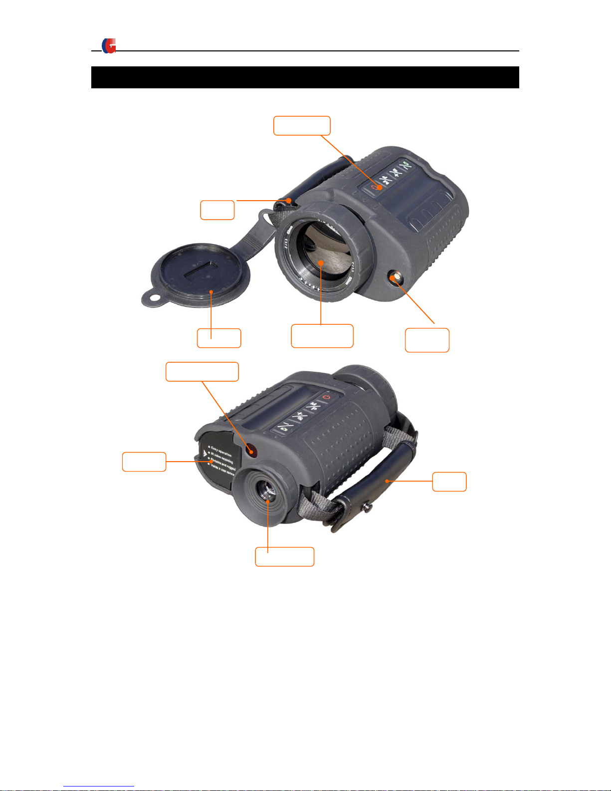
Chapter 4 Buttons and interface of imager
IR 518 Thermal Imager figure
Eye piece
Infrared lens
Wrist Strap
Buttons
Lens cap
Interface
Battery
cover
Hand strap
IR sensor
IR518 Thermal Imager User Manual
8
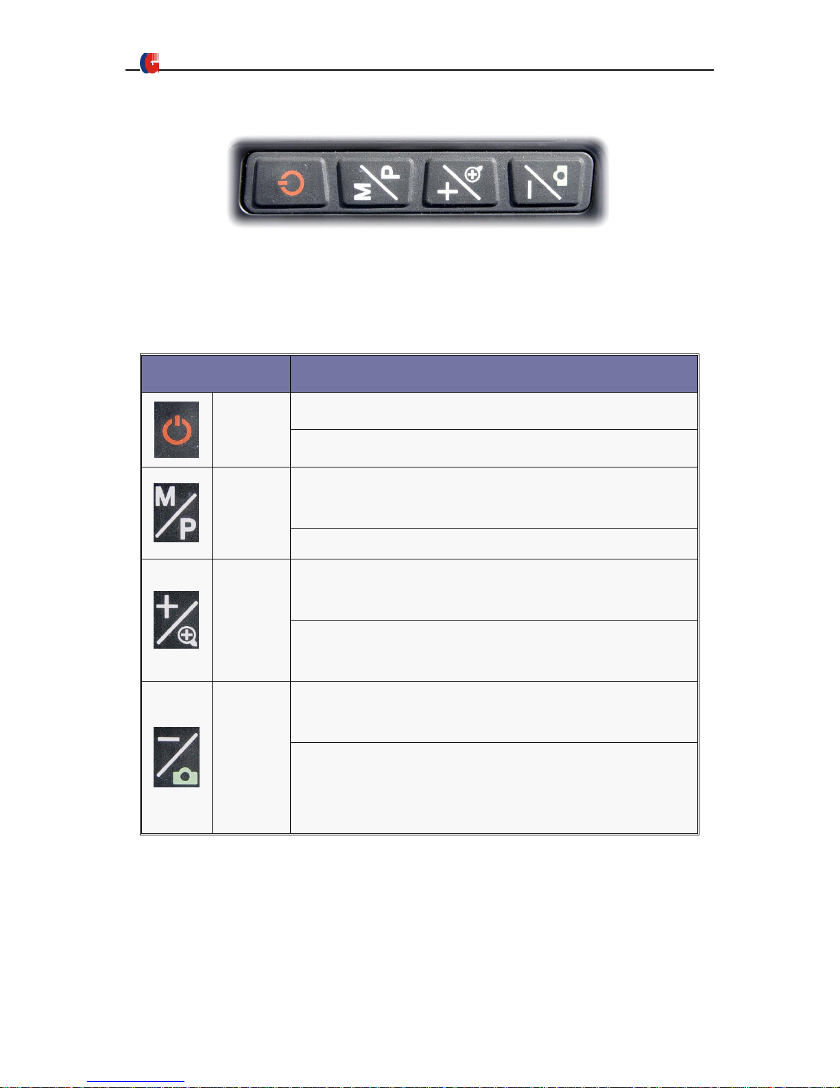
The function keyboard is on the top of IR518
Buttons Instruction
Buttons
Function
POWER
Press 5 sec to power on/off the imager
Short press to calibrate the imager manually.
M
When no menu displayed:Press 3 sec to bring out menu.
Short press to switch between white/black hot.
When menu displayed:Press this button to select the menu items
+
When menu displayed: Press this button to choose the menu
from left to right.
When no menu displayed: Switch between original image and 2X
image
-
When menu displayed: Press this button to choose the menu
from right to left.
When no menu displayed:Short press to take and save infrared
image.
Long press to take and save image video
IR518 imager can be used as handheld device or can be stably installed on tripod ,please see the
screw hold on the bottom side of the camera .
IR518 Thermal Imager User Manual
9
Chapter 5 Quick start guide
5.1. Preparation
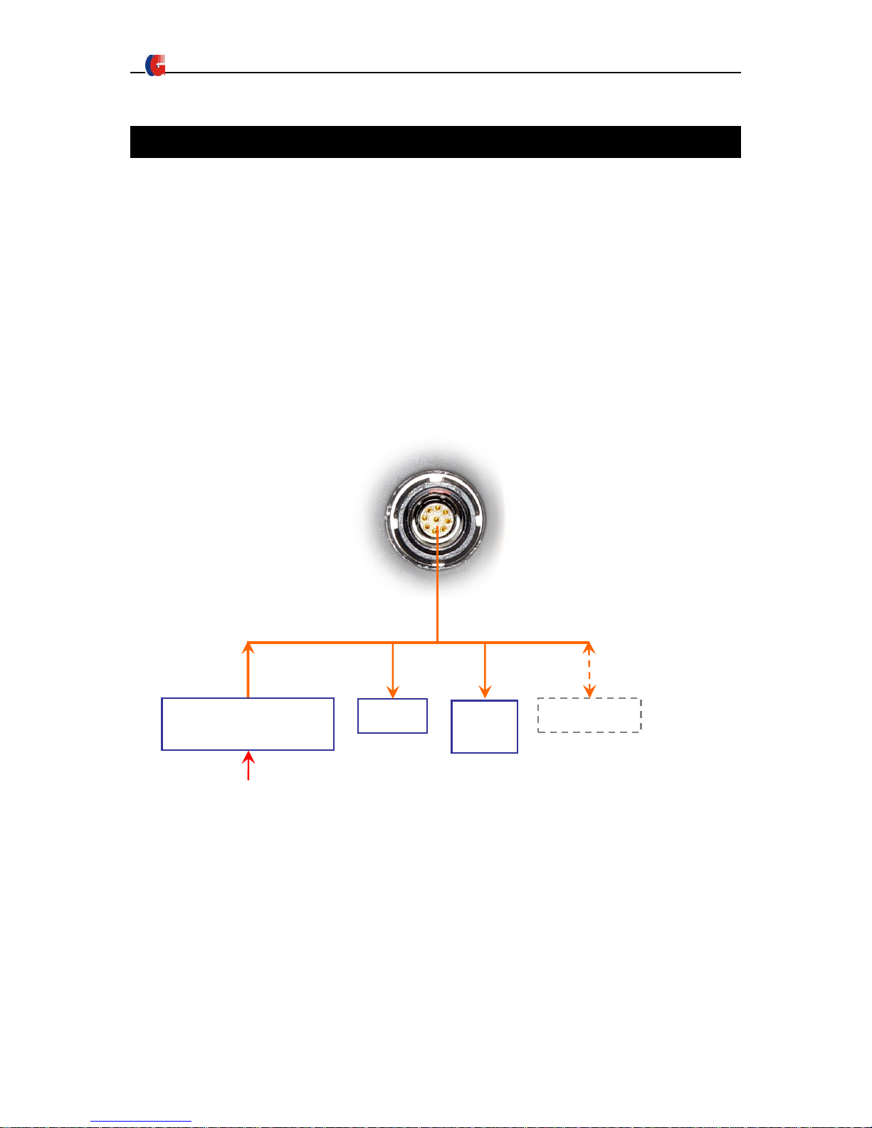
1) The operator could hand hold the IR518 Thermal Imager, or fix it on the tripod.
2) According to the thermal imager interface definition, connect the enclosed video/USB cable,
power cable and 9V power adapter to the display equipment and AC power shown as below
picture. When Insert the cable plug into the thermal camera socket, please aim the convex
part to the concave part and slightly insert.
Note: When the camera connected with the PC by USB port, all button operation will be
ineffective. Thus, please do not connect the camera with the PC when observing, and only
connecting when transmitting the picture or video. The RS232 communication function is
reserved.
110-240VAC→9VDC
Adapter
110-240VAC
Monitor
PC port
video
RS232
PC
USB
USB
9VDC
 Loading...