

Guide THERMOPRO TP9 User Manual

1
USER MANUAL
THERMOPROTM TP9 IR Thermal Camera

2
Thanks for selecting us, we advise you to read the user manual carefully before using the camera, which will help
you to use it properly. Please contact us if you have any questions.
The Quality Management System of Wuhan Guide Infrared Co., Ltd. is approved to ISO9001:2000 for the design
and manufacturing, stockholding, in-house repair and site servicing of non-contact temperature measuring
instrumentation.
Wuhan Guide Infrared Co., Ltd. reserves the right to make changes and improvements on any of the products
described in this manual without prior notice.
THERMOPRO
TM
TP9 Thermal Camera complies with current European directives relating to
electromagnetic compatibility and safety. (EMC directive 89/336/EEC; Low voltage directive
73/23/EEC).
Copyright
© Wuhan Guide Infrared Co., Ltd, 2008. All rights reserved worldwide. No parts of the products may be
reproduced, transmitted, transcribed or translated into any language or computer language in any form or by any
means, electronic, magnetic, optical, manual or otherwise, without the prior written permission of Wuhan Guide
Infrared Co., Ltd.
This manual must not, in whole or part, be copied, photocopied, reproduced, translated or transmitted to any
electronic medium or machine readable form without prior consent, in writing, from Wuhan Guide Infrared Co.,
Ltd.

3
Table of Contents
1. Cautions ............................................................................................................................................................ 4
2. System Configuration ........................................................................................................................................ 5
3. Technical Specification ...................................................................................................................................... 5
4. System Features ................................................................................................................................................ 7
5. Parts Described ................................................................................................................................................. 9
6. Assembly/Disassembly LCD ............................................................................................................................ 10
7. SD card In /Out ............................................................................................................................................... 11
8. Load in/Load out Battery ................................................................................................................................ 11
9. Charging Battery ............................................................................................................................................. 12
10. Operation Button Instruction ................................................................................................................ 13
11. Quick Start Guide ................................................................................................................................... 14
12. Operation Instruction ............................................................................................................................ 14
13. Instruction on Configure the USB Driver ............................................................................................... 33
14. Data Transfer to PC ................................................................................................................................ 40
15. TP9 wireless network connection method ............................................................................................ 40
16. Troubleshooting ..................................................................................................................................... 42
17. Typical Emissivity Values ........................................................................................................................ 43

4
1. Cautions
The following cautions must be adhered to at all times and must be considered in addition to any advised
precautions issued at the relevant worksite or work area
Keep the THERMOPROTM TP9 IR Thermal Camera steady during operation.
Do not use the THERMOPROTM TP9 IR Thermal Camera in temperature exceeding its working and storage
temperature ranges.
Do not direct the THERMOPROTM TP9 IR Thermal Camera at very high intensity radiation sources such as
the sun, carbon dioxide lasers or arc welders etc.
Do not expose the THERMOPROTM TP9 IR Thermal Camera to dust and moisture. When operating the unit
near water, ensure that the unit is adequately guarded against splashes. Always replace the lens cap when
the unit is not in operation.
When the THERMOPROTM TP9 IR Thermal Camera is not in use or is to be transported, ensure that the unit
and its accessories are stored in the protective carry case.
Do not jam the holes or loudspeaker on the camera body.
Do not re-switch on the camera until 15 seconds later after switching it off.
Do not throw, knock or vibrate intensely the camera and its components in order to keep them from
damage.
Do not attempt to open the camera body, as this action will void the warranty.
Keep the SD memory card for the exclusive use of the camera.
The THERMOPROTM TP9 IR Thermal Camera utilizes a Lithium Ion (Li-Ion) rechargeable battery pack. The
following safety precautions must be adhered to at all times to ensure the safe use of this equipment:
Do not disassemble or attempt to open the battery under any circumstances.
Do not expose the battery to fire or high temperatures.
Do not make the battery short circuit.
Do keep the battery off moisture or water.
Charging of the battery should only be carried out by using the recommended or supplied charging device.

5
2. System Configuration
Please ensure that the following items have been correctly supplied:
Standard Configuration:
IR Camera with visual camera, laser locator
35mm IR lens
5.7” VGA LCD Screen, 0.6” OLED viewfinder, touch pen
SD card & card reader
Two rechargeable Li-ion batteries and one special battery charger
AC Adapter & cable
VGA cable
USB extension cable
RS232/TV video cable
Guide IrAnalyser
®
analysis software
User manual
Packing box
Optional Configuration:
80mm Tele-lens
19mm Wide angle lens
2000℃ High temperature lens
Car adapter
3. Technical Specification
Imaging Performance
THERMAL
Detector type:
Uncooled FPA microbolometer (640× 480 pixels, 25μm)
Spectral Range:
8-14μm
Thermal Sensitivity:
0.05°С at 30°С
Field of View/ Focus:
25.8°× 19.5°/ 35mm
11.5°× 8.6°/ 80mm
45.7°× 35.1°/ 19mm
Focus:
Automatic or motorized
Electronic Zoom:
×2, ×4, x8
VISUAL
Built-in Digital Video:
5M

6
Image Presentation
External Display:
5.7″ high resolution color VGA LCD, 640× 480 pixels
Viewfinder
0.6″ built-in high resolution color OLED, 640× 480 pixels
Video Output:
60Hz VGA/ 50Hz PAL/ 60Hz NTSC switchable
Measurement
Temperature Range:
Filter 1: -20 °С- +250°С; (Down to -40°С optional)
Filter 2: 200°С- +800°С (up to +2000°С optional)
Accuracy:
Filter 1: ±1°С or ±1% of reading;
Filter 2: ±2°С or ±2% of reading
Measurement Modes:
Auto hot spot & auto alarm in live/ zoomed image & video; 8
movable spots, 8 movable & changeable areas displaying either
max, min, or average, vertical & horizontal line profile, histogram &
isotherm in live/zoomed/frozen/saved image & video
Emissivity Correction:
Variable from 0.01 to 1.00 (in 0.01 increment)
Measurement Features:
Automatic correction based on distance, relative humidity,
atmospheric transmission and external optics
Optics Transmission Correction:
Auto, based on signals from sensors
Image Storage
Type:
16GB SD card (8GB/32GB for optional)
File Format:
JPEG (An individual file consists of infrared image, visual image,
voice annotation and remarks if any)
Voice Annotation:
Up to 60 seconds per file
Remark Annotation:
Selected from preset marks
Video Record:
H.264 Compressed Video With Temperature Measurement
MPEG4 Compressed Vide Without Temperature Measurement
Laser Locator
Classification Type:
Class 2 semiconductor laser
Power System
Battery Type:
Rechargeable Li-ion Camcorder battery, field- replaceable
Charging System:
In camera or in battery charger, Vehicle Power Adapter (optional)
Battery Operating Time:
Over 2 hours continuous operation
External Power Operation:
9V DC
Environmental Specification
Operating Temperature:
-15°С- +50°С
Storage Temperature:
-20°С- +60°С
Humidity:
Operating and storing 10% to 95%, non- condensing
Encapsulation:
IP54 IEC 529 housing

7
Shock:
Operational: 25G, IEC 68-2-29
Vibration:
Operational: 2G, IEC 68-2-6
Interfaces
USB 2.0:
Real-time data transfer to PC; Image/Video transfer to PC
Video Output
VGA/PAL/NTSC
Wi-Fi
Built in 802.11.a/b/g
Illuminator
Built in adjustable LED
Physical Characteristics
Housing:
Magnalium
Weight:
0.85kg (excluding battery & LCD); 1.1kg(including battery & LCD)
Size:
186mm×106mm× 83mm (Standard Model)
Tripod interface:
1/4″- 20
4. System Features
4.1 New features
The highest-performance un-cooled IR detector (640×480 pixels, 25 microns) offers performance 300%
higher than traditional detectors of 320*240 pixels, 45 microns, more details is shown because of the small
pitch.
640*480 VGA LCD screen and 640*480 OLED viewfinders enable flexible high-resolution image
presentation.
Three options of the SD card (8G/16G/32G) enable the video storage in your IR camera.
Easily switchable VGA/ PAL/ NTSC video output simplifies video viewing; simultaneous video output on VGA
LCD screen, OLED viewfinder, a VGA display and a TV display is available.
Camera can be controlled by touch screen, voice, remote control handle or joystick & buttons, enabling the
camera use in any demanded application.
Intelligent auto speech recognition system and intuitive touch screen free hands or at least reduce hand
operation.
High-speed USB2.0 interface enables real-time data transfer, live video recording and camera control.
Real-time radiometric thermal video recording and JPEG image storage facilitate further analysis and report
generation.
Windows-style man-machine interface & status display screen showing component status reinforce the
user-friendly feature.
Compact & durable magnalium camera casing raises reliability and operation easiness.
4.2 Imaging Performance
Display 256-level gray and color thermal image on both VGA LCD screen and viewfinder.
Display 2
24
true color visual images.

8
Transfer live thermal video into PC via USB cable.
Auto or manual focusing of IR lens, manual focus on visual camera.
4.3 Temperature Measurement
Auto hot-spot tracing and center-cursor temperature measurement pinpoint the problem.
Auto calibration ensures high accuracy.
Up to 8 spots can be analyzed simultaneously in live or zoomed or frozen or saved images.
Up to 8 areas can be analyzed simultaneously in live or zoomed or frozen or saved images, showing
respective Max, Min or Average temperature within each area.
Line analysis can be done in live or zoomed or frozen or saved images; line profile can be switched into
horizontal or vertical coordinates system.
Isotherm analysis can be done in live or zoomed or frozen or saved images.
4.4 Image Storage
Live images can be frozen to be static images to do multiple-spot analysis, multiple-area analysis, line
analysis and isotherm analysis.
Frozen images, comprising radiometric data, infrared image, visual image, voice annotation and text
annotation, can be saved into 2GB SD card or the built-in flash memory in standard JPEG format.
Up to 60-second digital clip of voice can be recorded and saved for each image.
SD card can accommodate 1000 images and the built-in flash memory can store 450 images.
Live thermal video can be recorded onto PC via USB cable. Temperature measurement and different kinds
of analysis can be done on recorded video.
4.5 Image Playback
Images saved into SD card or the built-in flash memory can be replayed on the camera.
Temperature measurement and different kinds of analysis can be done on replayed images.
Voice annotation, text annotation and visual images saved together with thermal images can be replayed as
well.
Recorded thermal video can be replayed on PC.
Images saved in SD card and the built-in flash memory can be downloaded to PC for further analysis and
report generation with software Guide IrAnalyser®.
9
5. Parts Described
1
2
3
4
5
6
7
8
9
10
11
12
13
14
15
16
17
18
1. VGA LCD touch screen 2. IR lens
3. Laser indicator 4. Illuminator
5. Visual light 6. VGA video interface/ joystick interface
7. USB2.0 interface 8. Battery door
9. View finder 10. Microphone to record voice annotation
11. Joystick 12. F1~F4 keys
13. Shoulder strap interface 14. RS232/ TV video interface
15. External power supply interface 16. SD card slot
17.Button S、Button C、Button A 18. Power on button
1. Tightening gear; 2. Touch pen; 3. Hot shoe contact pins;
Lithium rechargeable battery Battery charger
10
RS232 / TV video cable
External VGA video cable
USB cable
AC adapter
If connecting the VGA cable and the video interface of RS232/ TV video cable to corresponding devices,
such as a VGA display device and a TV video display device, you can view the live video taken by the camera
simultaneously on VGA LCD touch screen, OLED viewfinder, the VGA display device and the TV video display
device.
6. Assembly/Disassembly LCD
The camera adopts the advanced Hot-shoe technology to realize the connection between the LCD and the
host, so cables are saved.
Put the hot-shoe connector into the guide rail on the top-end of the camera until the end.
Rotate the fixed rotary knob in a clockwise direction to make the hot-shoe connector and connecting base
match and locked.
LCD can support pitch adjusting around the horizontal axis, in order to reach a convenient observation
angle.
If you want to remove LCD, rotate the fixed knob in an anti-clockwise direction to break the lock between

11
the hot-shoe connector and the connecting base.
Slightly press the hot-shoe connector at the front end of the camera, and push it forward until it is
completely out of the guide rail of the hot-shoe connecting base.
Note:
Don’t forcefully install or disassemble LCD to avoid damaging the metal touch of the hot shoe.
Push LCD into the guide rail of the hot shoe, and make sure the fixed knob is locked well to avoid the bad
connect or separation of LCD.
Install or disassemble LCD in the shutdown mode.
7. SD card In /Out
Under power-off or boot-up status is both available for the SD card operation.
Open SD card door for the operation.
Insert SD card,please insert metal part into it and push it inside.
Take out SD card, press down and release it. Then it would be jump out.
If there is no SD card inside camera, the information bar will display as follows:
If there is a SD card inside it,this icon will disappear.
Caution:
Please do not turn off the camera when it is saving, opening and deleting images.
Please do not get out of SD card when it is saving, opening and deleting images.
Do not use this SD card for non-infrared thermal camera application.
8. Load in/Load out Battery
Pull out lock catch to open the battery compartment.
Push one battery metal part inside it until it knocked, and then close the battery gate.
12
Please turn off the camera before changing the battery.
Pull out of battery lock catch, and then take out the battery.
9. Charging Battery
There are only one way to charge battery:
Charging battery with the special battery charger
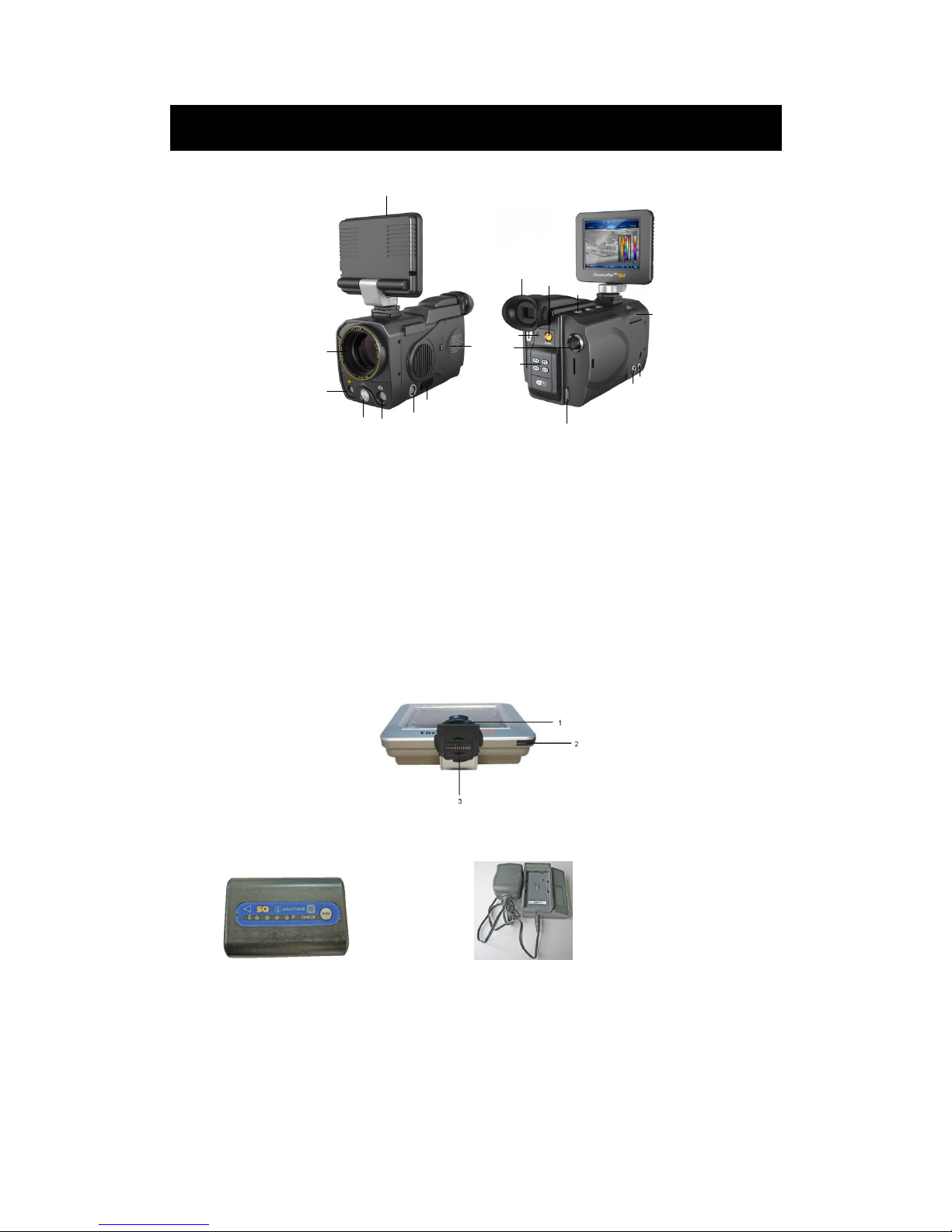
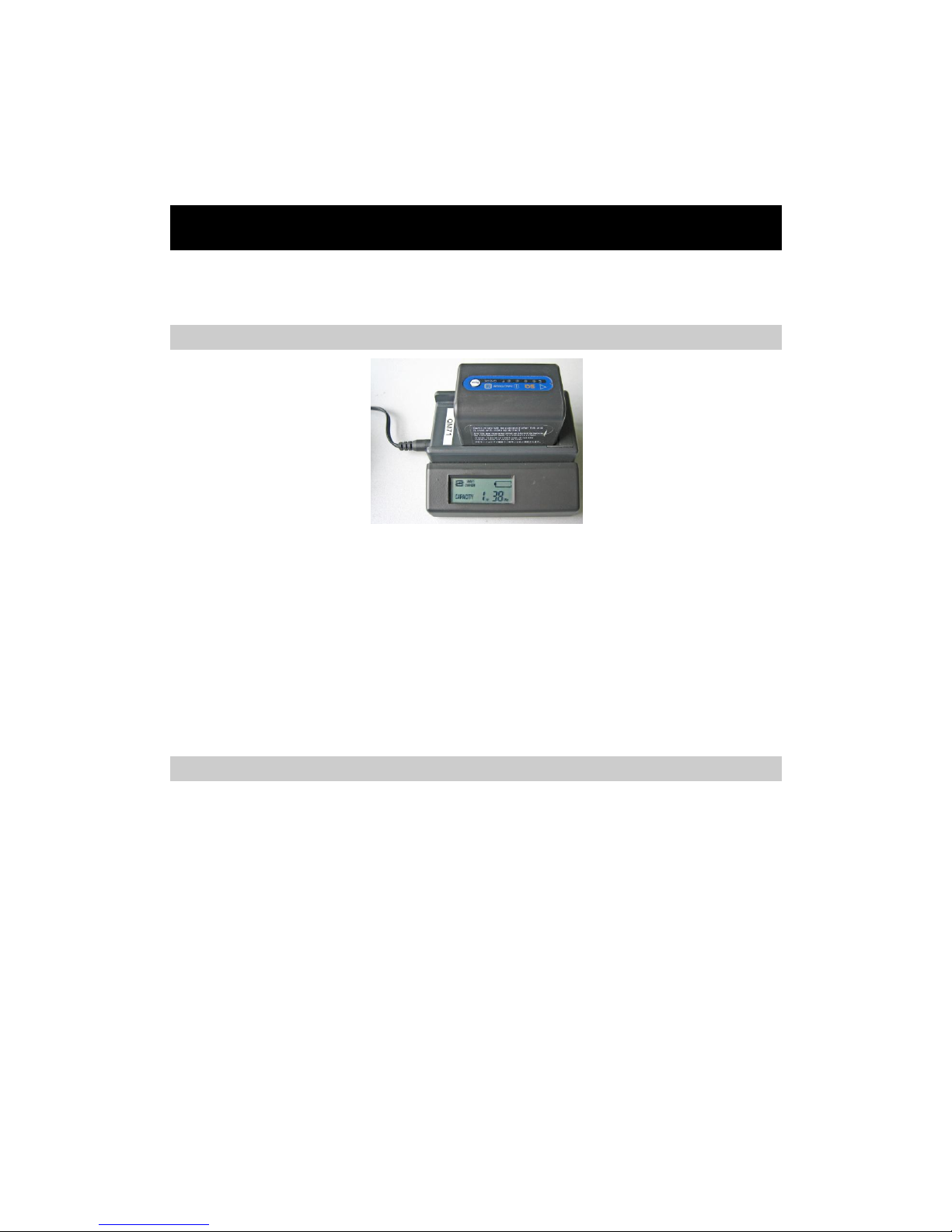
Charging battery with battery charger
Put the battery on the battery charger.
Connecting battery charger power.
The battery charger will make a sound after it starts charging, it will display “**Hr**Min” on the screen to
show battery capacity status.
The battery charger will also make a sound when battery charging finishes. It will display “FULL” on the
screen to show battery capacity full.
Take out the battery to put it into the camera.
We don’t recommend using the battery uncharged fully, for it will reduce the effective capacity.
Notes
The capacity of charging battery would be reduced when it is not using. Please recharge it when it is not
used for a long time.
Please remove battery out when infrared thermal camera isn’t used, and put it under dry environment.
Please use dry soft cloth to wipe metal contact of the battery.
Please do not try to open or disassemble the battery.
Please do not let the battery short circuit.

13
10. Operation Button Instruction
Power on/off
Press this button for 2 seconds to turn on/off the camera.
Joystick: Multifunctional Joystick
When it is under real-time infrared thermal status,moving up/down the joystick is manual focus, moving
right/left the joystick is zoom in.
Moving down the joystick to enter menu or parameter option,then moving the joystick to switch from each
menu and subsidiary menu, or changing the parameter value.
When the options on the menu are in high light, pressing the joystick vertically represents entering this menu or
the option.
When the tools bar is in high light, pressing the joystick vertically represents selecting and carrying out the
operations in these options.
Button S: Freeze/ Save
Press button S to freeze the image in real infrared thermal status, and press button again to save the picture into
SD card.
Button C: Cancel/Exit
Press button C to cancel without changing any parameters.
Press button C for 2 seconds in real infrared thermal status, then it will calibrate.
Button A: Palette/Filter
When it is in real time with basic information, shortly press button A for 2 seconds to swift from “auto” mode to
“manual” mode.
Press button A to switch from “max” to “min”, moving up/down joystick to change temperature value.
Press button A in real time without menu, then it could switch from standard temperature filter to high
temperature filter (250℃~800℃).
Button F1:
If the light option is on in the parameter setting,press “F1” button to open/close the light and adjust lightness.
Button F2: Infrared thermal image/Visual image
When there is no menu on the screen, press button“F2” to switch from thermal image to visual image.
Button F3: Laser Indication
When it is in real time without menu and laser indication option is on,pressing“F3”button to open/close the laser
indication.
Button F4: Auto Focus
When it is in real time without menu,press button“F4” to perform auto focus to make the image clear. (If the

14
target has no obvious contrast, auto focusing effect isn’t very good.)
11. Quick Start Guide
Ensure that the battery is fully charged and the SD memory card is inserted in the camera.
Insert the VGA LCD screen into the hot shoe and ensure it has locked into place.
Press button On/ Off for 2 seconds to switch on the camera.
Wait till the boot-up screen image disappears and uncover lens cap.
Aim the camera at the target. Press button F4 to automatically focus or move the joystick up or down to
manually focus.
Press button A for 2 seconds to switch between Auto and Manual modes. In manual mode, press button A
to shift between T-max and T-min and up or down the joystick to setup the values. Follow the
above-mentioned methods to adjust the display effect if required.
Use touch pen to touch the palettes and make selection among the 8 choices. Click the palette type and the
right-side palette, and then the set palette type can be changed.
In the auto mode, long press button A for 2 seconds to shift between temp-range filter, which adapts for
the different temperature range.
Press button F2 to switch between live visual image and thermal image. The visual light camera is in auto
mode without manual operation.
Press button S to freeze the live image.
Press button S to store the frozen image into SD memory card.
Press button S for 2 seconds to enter video recording menu in real-time mode and in no menu mode.
12. Operation Instruction
Power-on the camera
Press button On / Off for 2 seconds to power on the camera.
Then the loading image and boot-up screen flash for about one minute appear in the screen as shown below:
After the boot-up screen flash disappears, live image as shown below is displayed. Touch the screen or move the joystick
downward, basic information will be shown.
 Loading...