

Guide ThermoPro TP8 User Manual

User Manual
1
ThermoPro
TM
TP8 IR Thermal Camera
User Manual
Wuhan Guide Infrared Technology Co., Ltd.
No. 26 Shucheng Rd, Hongshan District, Wuhan 430070 P. R. China
Telephone: +86-27-8767 1991
Facsimile: +86-27-8767 1927
Email: overseas@guide-infrared.com
Internet: www.guide-infared.com
© Wuhan Guide Infrared Technology Co., Ltd., 2006
Publication No: ThermoPro
TM
TP8 UM 008

User Manual
2
The Quality Management System of Wuhan Guide Infrared Technology Co., Ltd. is approved
to ISO9001:2000 for the design and manufacture, stockholding, in-house repair and site
servicing of non-contact temperature measuring instrumentation.
Wuhan Guide Infrared Technology Co., Ltd. reserves the right to make changes and
improvements on any of the products described in this manual without prior notice.
ThermoPro
TM
TP8 IR Thermal Camera complies with current European
directives relating to electromagnetic compatibility and safety. (EMC
directive 89/336/EEC; Low voltage directive 73/23/EEC)
Copyright
© Wuhan Guide Infrared Technology Co., Ltd, 2006. All rights reserved worldwide. No parts of
the products may be reproduced, transmitted, transcribed or translated into any language or
computer language in any form or by any means, electronic, magnetic, optical, manual or
otherwise, without the prior written permission of Wuhan Guide Infrared Technology Co., Ltd.
This manual must not, in whole or part, be copied, photocopied, reproduced, translated or
transmitted to any electronic medium or machine readable form without prior consent, in
writing, from Wuhan Guide Infrared Technology Co., Ltd.

User Manual
3
Table of the Contents
Table of the Contents ................................................................................................................3
Introduction ...............................................................................................................................4
Precautions ...............................................................................................................................4
Maintenance..............................................................................................................................5
Calibration and Repair Philosophy............................................................................................6
Technical Support......................................................................................................................6
Feedback to Us .........................................................................................................................6
System Overview ......................................................................................................................7
System Configuration................................................................................................................7
Technical Specification..............................................................................................................8
System Features .....................................................................................................................12
Parts Described.......................................................................................................................14
Attaching and Detaching the LCD Screen ..............................................................................20
Inserting / Removing the SD Memory Card ............................................................................21
Inserting/ Replacing the Battery..............................................................................................22
Battery Charging .....................................................................................................................23
Introduction to Buttons & Joystick...........................................................................................25
Quick Start Guide....................................................................................................................28
Using the Camera ...................................................................................................................28
Using the Bluetooth Wireless Headset....................................................................................74
Video Output ...........................................................................................................................75
Transferring Data from the Camera to PC ..............................................................................76
Installing the Camera USB Driver to PC .................................................................................77
Controlling the Camera through RS232 Communication Protocol..........................................83
Troubleshooting ......................................................................................................................92
Emissivity ................................................................................................................................93
Typical Emissivity Values ........................................................................................................95

User Manual
4
Introduction
This publication provides the necessary information required to safely operate the
ThermoPro
TM
TP8 IR Thermal Camera
It is important to fully check all equipment with which you have been supplied
The equipment should be used, maintained and serviced by suitably trained personnel,
capable of carefully following the procedures and guidelines given in this User Manual
All User Manuals and leaflets should be read thoroughly before proceeding with operation of
the equipment
It is also advisable that all User Manuals and Instruction Leaflets supplied are kept readily
available, for reference when the equipment is in general use
Precautions
The following precautions must be adhered to at all times and must be considered in addition to
any advised precautions issued at the relevant worksite or work area
• Keep the THERMOPRO
TM
TP8 IR Thermal Camera steady during operation
• Do not use the THERMOPRO
TM
TP8 IR Thermal Camera in temperature exceeding
its working and storage temperature ranges
• Do not direct the THERMOPRO
TM
TP8 IR Thermal Camera at very high intensity
radiation sources such as the sun, carbon dioxide lasers or arc welders etc
• Do not expose the THERMOPRO
TM
TP8 IR Thermal Camera to dust and moisture.
When operating the unit near water, ensure that the unit is adequately guarded
against splashes. Always replace the lens cap when the unit is not in operation
• When the THERMOPRO
TM
TP8 IR Thermal Camera is not in use or is to be
transported, ensure that the unit and its accessories are stored in the protective
carry case

User Manual
5
• Do not jam the holes or loudspeaker on the camera body
• Do not re-switch on the camera until 15 seconds later after switching it off
• Do not throw, knock or vibrate intensely the camera and its components in order to
keep them from damage
• Do not attempt to open the camera body, as this action will void the warranty
• Keep the SD memory card for the exclusive use of the camera
The THERMOPRO
TM
TP8 IR Thermal Camera utilizes a Lithium Ion (Li-Ion) rechargeable
battery pack. The following safety precautions must be adhered to at all times to ensure the
safe use of this equipment
• Do not disassemble or attempt to open the battery under any circumstances
• Do not expose the battery to fire or high temperatures
• Do not short circuit the battery
• Do keep the battery off moisture or water
• Charging of the battery should only be carried out using the recommended or
supplied charging device
Maintenance
To ensure that the THERMOPRO
TM
TP8 IR Thermal Camera is kept in good working condition
and remains fully operational, the following guidelines should be adhered to at all times
Non-optical surfaces
The non-optical surfaces of the camera can be cleaned when required, with a soft cloth
dampened with water and a mild detergent
Optical surfaces
The optical surfaces of the camera lens should only be cleaned when visibly dirty. Care should
be taken to avoid touching the exposed lens surface, as skin acid left behind from fingerprints
can be damaging to coatings and lens substrates. Use only a proprietary lens cleaning tissue

User Manual
6
Calibration and Repair Philosophy
To ensure the accuracy and reliability of the THERMOPRO
TM
TP8 IR Thermal Camera, it is
highly recommended that the instrument be calibrated at 12 monthly intervals
Calibration or repair for the instrument can be obtained by either contacting the address/
telephone number on the cover of this User Manual, or by email to the following addresses:
overseas@guide-infrared.com
Caution
The THERMOPRO
TM
TP8 IR Thermal Camera does not incorporate any user serviceable parts.
Never attempt to disassemble or modify the camera. Opening the unit invalidates the warranty
Technical Support
Technical support for your Wuhan Guide Thermal Imaging System can be obtained by either
contacting the address / telephone number on the cover of this User Manual or by email to the
following address: overseas@guide-infrared.com
Feedback to Us
We have tested and verified the information in this manual to the best of our abilities. Yet as
we are committed to continuous development and progress, you might find features of the
product have been changed since the time of printing. You are appreciated to let us know
about any error you find, and your suggestions for further editions by either contacting the
address/telephone number on the cover of this User Manual or by email to the following
address: overseas@guide-infrared.com

User Manual
7
System Overview
THERMOPRO
TM
TP8, the most intelligent, innovative and integrated IR thermal imaging
system in the world
Improved on the most advanced IR package available now, integrating multiple technologies
never used in the industry, THERMOPRO
TM
TP8 is another ingenious solution Wuhan Guide
provides for professional IR thermographers around the world.
In a rugged, compact and durable magnalium casing, THERMOPRO
TM
TP8 offers a wide
assortment of unexpected features that enable thermographers to work with unprecedented
efficiency and productivity.
Exceeding all the existing IR radiometric cameras, it sets another new standard of the
first-class products for the whole industry.
System Configuration
Please ensure that the following items have been correctly supplied:
• IR Camera with visual camera, laser locator
• 35mm IR lens
• 3.5” VGA LCD Screen, 0.6” OLED viewfinder, touch pen
• 2GB SD card & card reader
• Bluetooth wireless headset
• Two rechargeable Li-ion batteries
• Battery charger
• AC Adapter & cable
• VGA cable
• USB extension cable
• RS232 communication & TV video cable

User Manual
8
• RS232 communication protocol
• USB driver
• Guide IrAnalyser
®
Software
• User manual
• Carry case & strap
Options
• Remote control handle
• Tele lens
• Wide angle lens
• Extended temperature range
Technical Specification
Imaging Performance
THERMAL
Detector type: Uncooled FPA microbolometer (384× 288 pixels,
35μm)
Spectral Range: 8-14μm
Thermal Sensitivity: 0.08°С at 30°С (Frame averaging algorithm)
Field of View/ Focus: 22°× 16°/ 35mm
Focus: Automatic or motorized
Electronic Zoom: ×1 to ×10 continuous zoom
VISUAL
Built-in Digital Video: CMOS Sensor, 1280× 1024 pixels, 2
15
colors

User Manual
9
Image Presentation
External Display: 3.5″ high resolution color VGA LCD, 640× 480 pixels
Viewfinder 0.6″ built-in high resolution color OLED, 640× 480
pixels
Video Output: VGA/PAL/ NTSC switchable
Man-Machine Communication
Touch Screen: Present and receive operator’s commands given by
touch
Auto Speech Recognition System: Automatically recognize and react to operators’ voice
commands
Remote Control Handle (optional) Respond as per operators’ operation
Joystick & Buttons: Respond as per operators’ operation
Menu: Microsoft® Windows style
Measurement
Temperature Range:
Filter 1: -20
°С- +250°С;
Filter 2: 100°С- +800°С (up to +2000°С optional)
Accuracy:
Filter 1: ±1°С or ±1% of reading;
Filter 2: ±2°С or ±2% of reading
Measurement Modes: Auto hot spot & auto alarm in live/ zoomed image &
video; 8 movable spots, 8 movable & changeable
areas displaying either max, min, or average, vertical
& horizontal line profile, histogram & isotherm in
live/zoomed/frozen/saved image & video
Emissivity Correction: Variable from 0.01 to 1.00 (in 0.01 increment)
Measurement Features:
Automatic correction based on distance, relative
humidity, atmospheric transmission and external

User Manual
10
optics
Optics Transmission Correction: Auto, based on signals from sensors
Image Storage
Type: Removable 2GB SD card or built-in flash memory
File Format: JPEG (An individual file consists of infrared image,
visual image, voice annotation and text annotation if
any)
Voice Annotation:
Up to 30 seconds per file (More than 30 seconds
optional)
Bluetooth wireless headset
Text Annotation: Selected from preset texts
Live Video Recording & Measurement & Storage
Recording: Thermal video recording to PC via USB2.0
Measurement: The same as image
Storage: In PC, capacity dependent on PC hard disk capacity
Optional Lenses
Field of View/ Focus: 7.7°× 5.8°/ 100mm
45.6°× 35°/ 16mm
Laser Locator
Classification Type: Class 2 semiconductor laser
Power System
Battery Type: Rechargeable Li-ion Camcorder battery, field-
replaceable
Charging System: In camera or in battery charger
Battery Operating Time: Over 2.5 hours continuous operation

User Manual
11
External Power Operation: AC adapter 110/ 220 VAC, 50/ 60Hz
Environmental Specification
Operating Temperature: -20°С- +60°С
Storage Temperature: -20°С- +60°С
Humidity: Operating and storing 10% to 95%, non- condensing
Encapsulation: IP54 IEC 529 housing
Shock: Operational: 25G, IEC 68-2-29
Vibration: Operational: 2G, IEC 68-2-6
Interfaces
USB 2.0: Real-time data transfer to PC & real-time control of
the camera on PC
RS232 communication: Control of camera on PC
Physical Characteristics
Housing: Magnalium
Weight: 0.85kg (excluding battery & LCD); 1.1kg(including
battery & LCD)
Size: 186mm×106mm× 83mm (Standard Model)
Tripod interface: 1/4″- 20

User Manual
12
System Features
Unique Features
• The highest-performance uncooled IR detector (384*288 pixels, 35 microns) offers
performance 45% higher than traditional detectors of 320*240 pixels, 45 microns
• 640*480 LCD screen and 640*480 OLED viewfinder enable flexible high-resolution image
presentation
• Easily switchable VGA/ PAL/ NTSC video output simplifies video viewing; simultaneous
video output on VGA LCD screen, OLED viewfinder, a VGA display and a TV display is
available
• Camera can be controlled by touch screen, voice, remote control handle or joystick &
buttons, enabling the camera use in any demanded application
• Intelligent auto speech recognition system and intuitive touch screen free hands or at least
reduce hand operation
• Bluetooth voice recording enhances operators’ safety
• Real-time radiometric thermal video recording and JPEG image storage facilitate further
analysis and report generation
• Ultra large capacity SD memory card and built-in flash memory offer easy in-field storage
• High-speed USB2.0 interface enables real-time data transfer, live video recording and
camera control
• Windows-style man-machine interface & status display screen showing component status
reinforce the user-friendly feature
• Compact & durable magnalium camera casing raises reliability and operation easiness
• Robust on board analysis enhances operators’ efficiency & productivity
• Hot shoe technology enables hot swap of the VGA LCD screen and non-cable-connection
of the VGA LCD screen with camera body

User Manual
13
Imaging performance
• Display 256-level gray and color thermal image on both VGA LCD screen and viewfinder
• Display true color visual image on both VGA LCD screen and OLED viewfinder
• Output both thermal and visual video to other display devices (e.g. VGA display or TV set)
• Transfer live thermal video into PC via USB cable
• Continuously zoom in or out thermal image from x1 to x10
• Auto or motorized focusing of IR lens
Temperature measurement
• Auto calibration ensures high accuracy
• Auto hot-spot tracing and center-cursor temperature measurement pinpoint the problem
• Up to 8 spots can be analyzed simultaneously in live or zoomed or frozen or saved images
• Up to 8 areas can be analyzed simultaneously in live or zoomed or frozen or saved images,
showing respective Max, Min or Average temperature within each area
• Line analysis can be done in live or zoomed or frozen or saved images; line profile can be
switched into horizontal or vertical coordinates system
• Histogram analysis can be done in live or zoomed or frozen or saved images
• Isotherm analysis can be done in live or zoomed or frozen or saved images
Image Storage
• Live images can be frozen to be static images to do multiple-spot analysis, multiple-area
analysis, line analysis and isotherm analysis
• Frozen images, comprising radiometric data, infrared image, visual image, voice
annotation and text annotation, can be saved into 2GB SD card or the built-in flash
memory in standard JPEG format
• Up to 30-second digital clip of voice can be recorded and saved for each image

User Manual
14
• SD card can accommodate 1000 images and the built-in flash memory can store 450
images
• Live thermal video can be recorded onto PC via USB cable. Temperature measurement
and different kinds of analysis can be done on recorded video
Image Playback
• Images saved into SD card or the built-in flash memory can be replayed on the camera
• Temperature measurement and different kinds of analysis can be done on replayed
images
• Voice annotation, text annotation and visual images saved together with thermal images
can be replayed as well
• Recorded thermal video can be replayed on PC
• Images saved in SD card and the built-in flash memory can be downloaded to PC for
further analysis and report generation with software Guide IrAnalyser
®
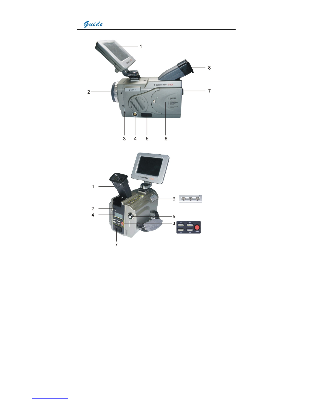
Parts Described
1. VGA LCD touch screen 2. IR lens
3. Visual focusing gear 4. VGA video interface
5. USB2.0 interface 6. Battery door
7. Buckle for neck strap 8. Viewfinder
User Manual
15
User Manual
16
1. Dioptre adjuster 2. Microphone to record voice annotation
3. F1-F4 function buttons and power button
4. Status display screen for power status, USB, Bluetooth & SD card memory status
5. Joystick 6. Button S, Button C and Button A
7. Bluetooth window
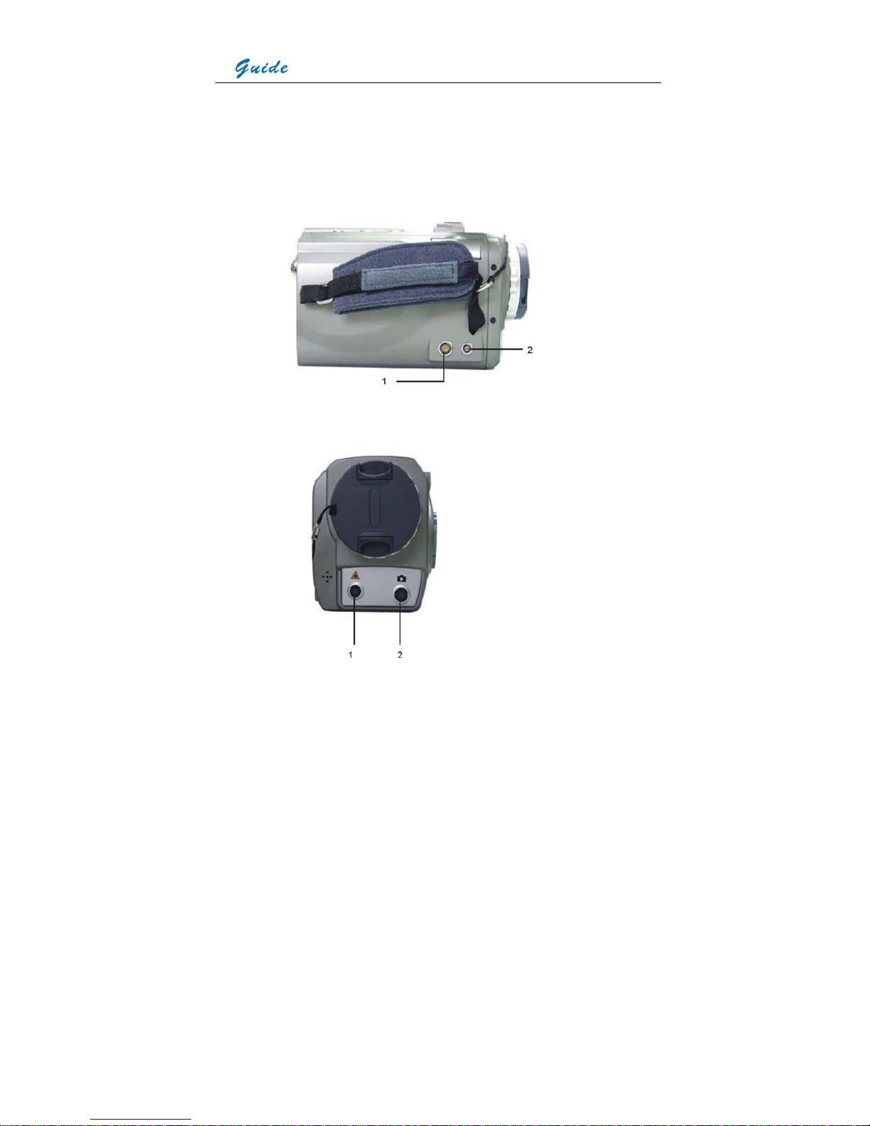
1. RS232/ TV video interface 2. Power interface
1. Laser locator 2. Visual camera
User Manual
17
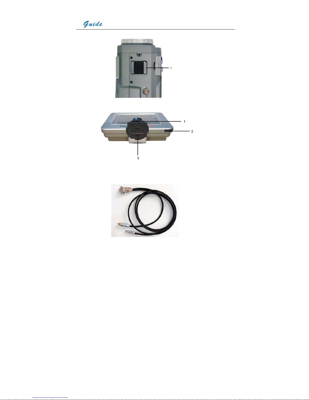
1. LCD mount
1. Tightening gear 2. Touch pen
3. Contact pins at the LCD screen foot
User Manual
18
RS232 and TV Video cable: Interfaces from the top down are respectively: RS232 interface to
PC, TV Video interface to a TV Video display device, TV Video/RS232 interface to the TV
Video /RS232 interface on camera
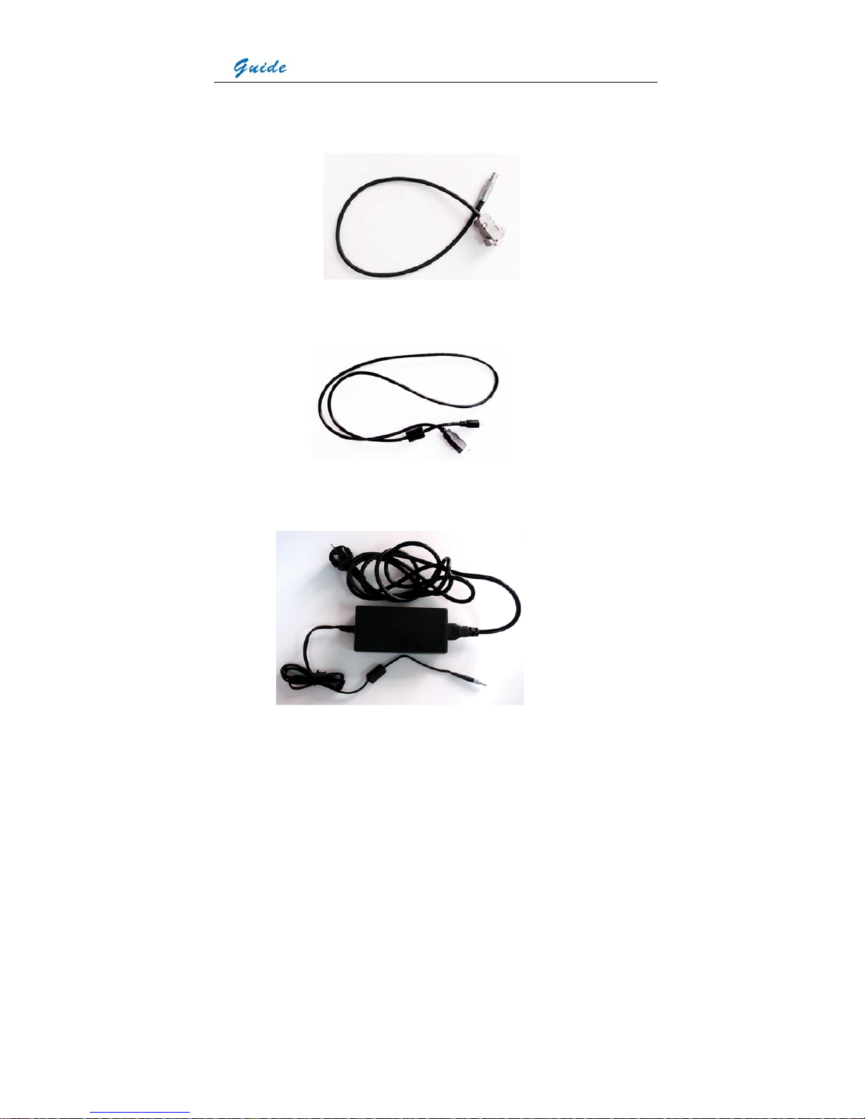
VGA cable: Interfaces from the top down are respectively: VGA video interface to the VGA
interface on camera, VGA interface to a VGA display device
USB extension cable: Interfaces from the top down are respectively: Interface to the camera
USB2.0 interface, interface to a USB interface on PC
User Manual
19
AC adapter and cable: Interfaces from the top down are respectively: Interface to be inserted
to the power interface on camera, plug to be connected to a socket or wall outlet
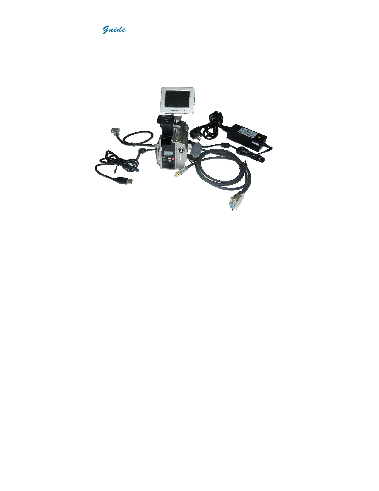
Camera with cables: from the top down and from left to right, the camera is connected with
VGA cable, USB extension cable, AC adapter cable and RS232/ TV video cable.
• If connecting the VGA cable and the video interface of RS232/ TV video cable to
corresponding devices, such as a VGA display device and a TV video display device, you
can view the live video taken by the camera simultaneously on VGA LCD touch screen,
OLED viewfinder, the VGA display device and the TV video display device.
• If connecting the RS232 interface of RS232/ TV video cable to a PC with RS232
communication port, you can view the live video on the video display device and
meanwhile control the camera on PC via RS232 communication protocol.

User Manual
20
• If only connecting the USB extension cable to a PC with USB2.0 interface and running the
corresponding menu commands of Guide IrAnalyser® software (e.g. sub-command
Device Video of command Video under menu File), you can view the live thermal video on
PC, control the camera on PC and also record live thermal video into PC.
• If connecting all the cables above to corresponding devices and execute the corresponding
commands in the Guide IrAnalyser® software (i.e. sub-command Device Video of
command Video under menu File), the camera will switch to USB mode immediately. Now
you can view the live video on PC, control the camera on PC and also record live thermal
video into PC with the help of Guide IrAnalyser® software, but at the meantime, the VGA
LCD touch screen, OLED viewfinder, VGA display device and TV video display device will
display prompt “USB Mode” only.
Rechargeable lithium battery Battery charger Bluetooth wireless headset
Attaching and Detaching the LCD Screen
Attaching the LCD screen:
• Mount the LCD screen to the camera by sliding the LCD screen foot into the mount on top
of the camera. Then rotate the tightening gear clockwise to make the LCD screen locked in
place

User Manual
21
• Tilt the LCD screen backward till you view the image comfortably
Detaching the LCD screen:
• Rotate the tightening gear anticlockwise to loose the LCD screen foot
• Keep the LCD screen depressed and slide the LCD screen foot from the mount
Notes for the LCD screen:
• Although the LCD screen utilizes hot shoe technology, it is still advisable to switch off the
camera before attaching or detaching the LCD screen
• Do not force the LCD screen into or out of the mount to avoid damage of the contact pins
under the LCD screen foot
• When sliding the LCD screen out of the mount, do keep it depressed to avoid damage of
the contact pins
• The tightening gear must be rotated into place after the LCD screen has been slid into the
mount
Inserting / Removing the SD Memory Card
• To insert or remove a SD memory card, open the SD memory card door
• To insert a SD memory card, slide the card with the terminals pointing downwards and the
obverse outwards till you hear a slight sound, as shown in the figure below

User Manual
22
• To remove a SD memory card, press the card downwards and then release it. It will
bounce to be pulled it from the camera
Notes for the SD memory cards:
• Ensure that saving or opening of images is complete before removing the SD memory card
• Do not use the SD memory card as a common removable disk for storing other information
than images or video taken by the camera
Inserting/ Replacing the Battery
• Open the battery door by sliding the release button right, as shown below.
• Insert a fully charged battery with the charge terminals pointing inwards and slide in the
battery until you hear a clear sound given by the release button to ensure the battery has
been locked into place.
• The battery level is displayed in the status display screen at the back of the camera. When
it is to be used up (i.e. the camera will automatically switch off in 15 minutes), an audible
sound alarm will activate and the battery level symbol in the status display screen will
flicker. At this point the battery needs to be replaced by a fully charged one
• Before replacing the battery, ensure that the camera is powered off

User Manual
23
• To remove the battery, open the battery door, keep the battery depressed and then press
the pop-up button. Keep the pop-up button depressed, release the battery, then the
battery will bounce and you can pull it from the camera. When pulling the battery, please
still keep the pop-up button depressed
• Replace a fully charged battery as above instructed
Notes for the battery:
• Do slide the battery into the battery chamber until you hear a clear sound given by the
release button. Otherwise, the battery is not locked into place and the camera cannot work
well because of unstable power supply.
• When pulling the battery out of the camera, please ensure the pop-up button is depressed
till the battery finally offs the camera
• In the interim of replacing the battery, AC adapter can be connected to the camera without
powering off the camera. Then the AC adapter starts supplying power for the camera and
you can replace the battery with a fully charged one without powering off the camera. After
replacement, you can disconnect the AC adapter from the camera.
Battery Charging
Two methods are available to charge batteries:
• Charging in the camera
• Charging in an external battery charger
Charging in camera
• Properly insert the battery into the battery door and close the door; connect the camera to
AC adapter through the AC adapter cable, and then connect the AC adapter to a socket or
wall outlet
User Manual
24
• Now charging starts. While charging, the battery level symbol will be rolling in the status
display screen. Once the battery is fully charged, the symbol will become steady.
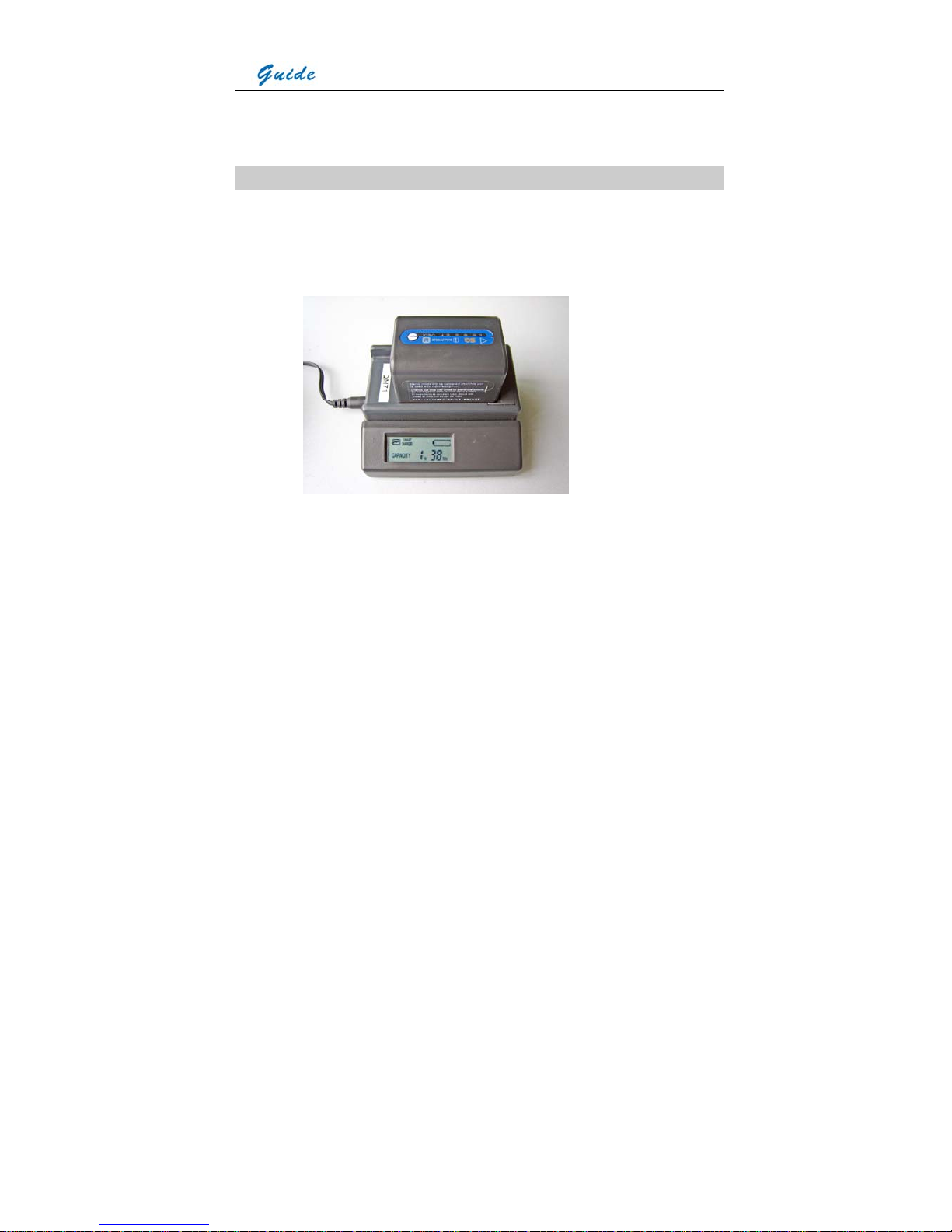
Charging in an external battery charger
• Insert the battery into the battery charger. This is done by aligning the end surface of the
battery pack to the edge of the terminal shutter of this unit, then fitting and sliding the
battery packing in the direction of the arrow.
• Connect the charger to a wall outlet or socket
• The battery charger will utter an audible sound to indicate charging start and the battery
level symbol will flash in its LCD screen. Besides the battery level symbol, its LCD screen
also shows the battery capacity by ** Hr ** Min. The capacity will increases as charging
goes on. While charging, the charge lamps on the top of the battery pack will light in turn,
indicating charging is going on.
• When normal charge is completed, the charger will give an audible sound, display a
prompt Full & the battery capacity in its LCD screen and stop the battery level symbol from
flashing. The charge lamps on the top of the battery pack also go out.
• Remove the battery pack when required. It can be used even if the charging is not
completed

User Manual
25
• Once the battery is fully charged it can be used with the camera
Additional Information
• All rechargeable batteries gradually lose their charge over time when they are left in
storage. If the battery is to be left in storage or for a period of non-use, a 'top-off' charge
should be carried out prior to use
• Always remove the battery from the equipment or charger when not in use. Store the
battery in a cool and dry place
• Periodically wipe the metal battery terminals with a soft, dry cloth
• Do not attempt to open or disassemble the battery
• Do not short circuit the battery by directly connecting the metal terminals
• Ensure that no metal objects touch the terminals
Introduction to Buttons & Joystick
Button On/Off: Power supply control
Keep button On/Off depressed for 3 seconds to switch on or off the camera.
Joystick: Multiple functions
When there is no menu displayed in live thermal image, move the joystick up or down to
adjust focus and left or right to zoom in or out the image continuously. When there is no menu
displayed in frozen or saved thermal image, move the joystick in all directions to move the
centre cursor to measure temperature of any spot in the image.
Press the joystick to enter all the menus; move it up, down, left and right to toggle between
different sub-menus or menu options or to alter values of different parameters.
When there is a dialog box displayed in thermal image, press the joystick to confirm selection

User Manual
26
and close the box.
When an option in the toolbar is highlighted, press the joystick to select this option and
execute the command corresponding to it.
Button S: Freeze & save control, option switch
Press button S to freeze a live/zoomed thermal image and press it again to save it into the
built-in flash memory or SD memory card.
Press button S to toggle between the 8 spots and 8 areas while doing spot and area analysis
on live or frozen or saved thermal images
Press button S to switch between horizontal and vertical coordinate systems when doing line
analysis on live or frozen or saved thermal images
Press button S to switch between options or buttons in menus or dialog boxes
Button C: Cancel
Press button C to cancel a dialog box or menu and return to the live/zoomed thermal image
When there is no menu or dialog box in live/zoomed thermal image, keep it depressed and
then press button S to perform a non-uniformity calibration.
Button A: Temperature range, filter & palette control
When there is no menu displayed in live/zoomed thermal image, keep button A depressed for
2 seconds and then release it to switch between its three modes Auto1, Auto2 and Manual,
with the corresponding prompt “Auto1” or “Auto2” or “Manual” shown in the status bar at the
left bottom of the image. Brightness and contrast of the image are controlled automatically in
the two auto modes and can be adjusted manually in manual mode.
When there is no menu displayed in live/zoomed thermal image, press button A for an instant
to select the temperature setup menu at the right side of the image. Move the joystick up or
down to toggle between its options Tmax, palette, Tmin and filter range, move it left or right to

User Manual
27
change their respective values.
Button F1: Sleep mode
Pressing button F1 in the normal working mode can switch to sleep mode, in which all the
video outputs are turned off and the red indicator light at the back of the camera flickers.
Pressing it in sleep mode can switch into the normal working mode, in which the red indicator
light at the back of the camera shine steady.
Button F2: Thermal & visual image switch
Pressing button F2 in live, zoomed, frozen or saved thermal images can switch to visual
image. Vice versa.
Button F3: Laser locater/ Histogram control
When option Laser in sub-menu Function of menu Parameter is set as On, press button F3 in
live/zoomed thermal image to turn on the laser locater and press it again to turn off the laser
locater.
When option Histogram in sub-menu Function of menu Parameter is set as On, press button
F3 in frozen or saved thermal image to display or close histogram
Button F4: Auto focusing control
When there is no menu or dialog box in live/zoomed thermal image, keep button F4
depressed till a frame appears in the image, aim the frame at the target to be focused and
then release button F4, then the camera will automatically focus till getting a clear image of
the target.

User Manual
28
Quick Start Guide
• Ensure that the battery is fully charged and the SD memory card is inserted in the camera
• Insert the VGA LCD screen into the mounting foot and ensure it has locked into place
• Keep button On/ Off depressed for 2 seconds to switch on the camera
• Wait till the boot screen image disappears and uncover lens cap. Non Uniformity
Calibration (NUC) is performed automatically
• Aim the camera at the target
• Press button F4 to automatically focus or move the joystick up or down to manually focus
• Move the dioptre adjuster to get a clear image in the viewfinder
• Press button A for 2 seconds to switch between Auto1, Auto2 and Manual modes
• Press button A and release it instantly and then adjust Tmax, palette, Tmin and filter if
necessary
• Press button F2 to switch to live visual image
• In visual image, rotate the visual focusing gear at the left front of the camera body to
manually focus
• Press button F2 to switch to live thermal image
• Press button S to freeze the live image
• Press button S to store the frozen image into SD memory card or built-in flash memory of
the camera
• Press button C to return to the live thermal image
Using the Camera
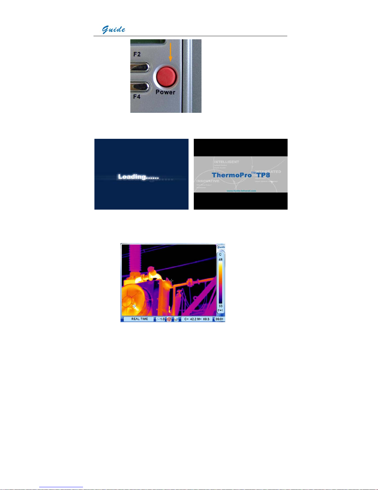
Powering on the camera
Keep button On/ Off depressed for 2 seconds to power on the camera.
User Manual
29
Then the loading image and boot screen flash as shown below appear in the screen
successively with music.
After the boot screen flash disappears, live image as shown below is displayed, with Guide
logo and temperature setup menu lying at the right side, status bar, zoom bar, speech control
bar, memory media bar, temperature display bar and time bar lying at the bottom.
 Loading...