

Page 1
SceneScan User’s Guide
W
A
R
R
A
N
T
Y
S
e
e
o
u
r
s
t
a
n
d
a
r
d
t
e
r
m
s
o
f
s
a
l
e
Q
U
A
L
I
T
Y
A
S
S
U
R
E
D
3
YEAR
Guidance Marine Ltd, 5 Tiber Way, Meridian Business Park, Leicester, LE19 1QP, UK
T: +44116 229 2600 E: sales@guidance.eu.com
Targetless position
reference sensor
www.guidance.eu.com
www.marine.direct
Page 2
SceneScan User’s Guide
LASER
1M
Print Colour
Black
Print Colour
Yellow
100.00 mm
Scale 1:1
Material
White
Issue Date: 11/10/2018
Document No: 94-0561-A
Serial No:
Sensor Software Version: Client Software Version:
Date of Shipment from UK:
Guidance Marine Ltd,
5 Tiber Way
Meridian Business Park
Leicester
LE19 1QP
UK
Tel: +44 116 229 2600
UK Support: +44 116 229 2665
(365 days a year, 08:00 - 20:00 hours UTC)
customerservices.uk@guidance.eu.com
USA Support: +1 504 305-1120
customerservices.us@guidance.eu.com
Asia Support: +65 6734 6365
customerservices.sg@guidance.eu.com
Web: www.guidance.eu.com/customer-support
Class 1M Laser Product
Complies with EN 60825-1
Complies with USA CFR 1040.10 & 1040.11
except for deviations pursuant to Laser Notice
No 50 26 Jul 2001
Copyright © Guidance Marine Limited. All Rights Reserved.
Copyright in the whole and every part of this document belongs to Guidance Marine
Limited (the “Owner”) and may not be used, sold, transferred, copied or reproduced in
whole or in part in any manner or form or in or on any media to any person other than
in accordance with the terms of the Owner’s Agreement or otherwise without the prior
written consent of the Owner. “SceneScan” is a registered trademark of Guidance Marine
Ltd. All other brand or product names are trademarks or registered trademarks of their
respective companies or organisations.
l 2l
Page 3

Table of Contents
Introduction ......................................................................................................5
Welcome �����������������������������������������������������������������������������������������������������������������������6
System Overview ����������������������������������������������������������������������������������������������������������7
SceneScan Sensor Part Names ����������������������������������������������������������������������������������� 8
Getting Started.................................................................................................9
Start Up and Shut Down ��������������������������������������������������������������������������������������������10
Start Up ����������������������������������������������������������������������������������������������������������������������������������������������� 10
Shut Down ������������������������������������������������������������������������������������������������������������������������������������������� 10
Targetless Tracking ����������������������������������������������������������������������������������������������������� 11
Overview of Targetless Tracking ����������������������������������������������������������������������������������������������������������11
Blanking Zones ������������������������������������������������������������������������������������������������������������������������������������ 11
Tracking Overview ������������������������������������������������������������������������������������������������������������������������������� 12
Screen Layout ������������������������������������������������������������������������������������������������������������13
Main Screen and Bird's Eye View (BEV) ����������������������������������������������������������������������������������������������14
Side Bar ����������������������������������������������������������������������������������������������������������������������������������������������� 16
Hotkey Buttons ������������������������������������������������������������������������������������������������������������������������������������ 17
Menu Pane ������������������������������������������������������������������������������������������������������������������������������������������18
Tracking Information Quality ��������������������������������������������������������������������������������������� 19
Display Settings ����������������������������������������������������������������������������������������������������������20
Vessel Orientation �������������������������������������������������������������������������������������������������������22
To set Vessel Orientation ���������������������������������������������������������������������������������������������������������������������22
1� Navigate to Advanced > Display Options > Layout� �����������������������������������������������������������������������22
2� Click on the vessel outline that points in the required direction� �����������������������������������������������������22
Tracking Basics .............................................................................................. 23
Operating Blanking Zones ������������������������������������������������������������������������������������������ 24
Dynamic Blanking Zone ����������������������������������������������������������������������������������������������������������������������24
Setting the Dynamic Blanking Zone ���������������������������������������������������������������������������������������������������� 24
Scanner Tilt Controls �������������������������������������������������������������������������������������������������� 25
Scanner Tilt Modes �����������������������������������������������������������������������������������������������������������������������������25
Spirit Level ������������������������������������������������������������������������������������������������������������������������������������������� 25
Tracking ���������������������������������������������������������������������������������������������������������������������� 26
To Start Tracking ���������������������������������������������������������������������������������������������������������������������������������� 26
To Stop Tracking ���������������������������������������������������������������������������������������������������������������������������������� 26
Adjusting the Scene Reference Point �������������������������������������������������������������������������������������������������� 27
Enabling DP Output ����������������������������������������������������������������������������������������������������������������������������� 28
Tracking Lost ��������������������������������������������������������������������������������������������������������������������������������������� 28
Manual Tilt Mode ��������������������������������������������������������������������������������������������������������������������������������� 28
Positional Display Modes ������������������������������������������������������������������������������������������� 29
Range, Bearing & Heading ������������������������������������������������������������������������������������������������������������������ 29
A and B Axes (A Pos and B Pos) ��������������������������������������������������������������������������������������������������������� 30
Multi-Dashboard SceneScan Systems .................................................. 31
SceneScan Dashboard - Monitoring Mode ���������������������������������������������������������������� 32
SceneScan Dashboard - In Command Mode ������������������������������������������������������������33
Support Information ................................................................................... 34
Low Temperature Operation ���������������������������������������������������������������������������������������35
Working with Alarms ���������������������������������������������������������������������������������������������������36
Filtering Alarms ������������������������������������������������������������������������������������������������������������������������������������ 36
Dynamic Positioning Feed ������������������������������������������������������������������������������������������37
Network Communications Settings ����������������������������������������������������������������������������38
Data Logging ������������������������������������������������������������������������������������������������������������� 39
Serial Numbers & Software Versions �������������������������������������������������������������������������� 41
Product Label �������������������������������������������������������������������������������������������������������������������������������������� 41
Software Version Information ��������������������������������������������������������������������������������������������������������������41
Troubleshooting ........................................................................................... 42
Contact Details ������������������������������������������������������������������������������������������������������������������������������������ 42
How to report issues ���������������������������������������������������������������������������������������������������������������������������42
Problems and Possible Remedies������������������������������������������������������������������������������43
SceneScan Fuse Information �������������������������������������������������������������������������������������44
Installing the SceneScan Hardware ....................................................... 45
3
Page 4

Table of Contents (continued)
Where to Mount the Sensor ���������������������������������������������������������������������������������������46
Sensor Dimensions and Mounting Template ��������������������������������������������������������������47
Installing the Cables .................................................................................... 48
Cable Specifications ��������������������������������������������������������������������������������������������������49
UPS Specifications ����������������������������������������������������������������������������������������������������� 50
SceneScan Sensor Connections ��������������������������������������������������������������������������������51
To Connect a Cable to the SceneScan Sensor ����������������������������������������������������������������������������������� 51
Connecting the Power Cable ��������������������������������������������������������������������������������������������������������������51
SceneScan Client and DP Feed Connections ����������������������������������������������������������� 52
Cable Routing Diagrams ��������������������������������������������������������������������������������������������53
Installing the Control PC ............................................................................ 55
Installing SceneScan Client Software onto a Computer ��������������������������������������������56
Upgrading the Sensor Software ��������������������������������������������������������������������������������� 57
Conguring the SceneScan System ..................................................... 58
Using the Service Interface ����������������������������������������������������������������������������������������59
Network Communication Settings �����������������������������������������������������������������������������60
Vessel Parameters ������������������������������������������������������������������������������������������������������62
Static Blanking Zones ������������������������������������������������������������������������������������������������65
Dynamic Positioning Feed Configuration ������������������������������������������������������������������� 66
DP Feed Behaviour ����������������������������������������������������������������������������������������������������67
System Parameters ���������������������������������������������������������������������������������������������������� 69
DP Message Types �����������������������������������������������������������������������������������������������������71
NMEA0183R Format ���������������������������������������������������������������������������������������������������������������������������71
NMEA0183P Format ����������������������������������������������������������������������������������������������������������������������������71
ASCII17 Format ����������������������������������������������������������������������������������������������������������������������������������� 72
Kongsberg Standard ���������������������������������������������������������������������������������������������������������������������������72
MT Custom DP String �������������������������������������������������������������������������������������������������������������������������73
Rolls-Royce Custom DP String ����������������������������������������������������������������������������������������������������������� 74
Kongsberg (Custom) ���������������������������������������������������������������������������������������������������������������������������75
Service Schedule ��������������������������������������������������������������������������������������������������������76
SceneScan Installation Checklist ������������������������������������������������������������������������������� 77
Index ��������������������������������������������������������������������������������������������������������������������������� 78
Document History ������������������������������������������������������������������������������������������������������80
l
4
Page 5

Introduction
This section provides an introduction and overview of the SceneScan system.
It contains the following sections:
Welcome (page 6)
•
System Overview (page 7)
•
SceneScan Sensor Part Names (page 8)
•
l
5
Page 6
Welcome
Welcome to the SceneScan User Guide. It explains how to:
• Use the SceneScan system
• Physically install the system
• Install and operate the Dashboard software
• Install the Service Interface
Note: Installation of a SceneScan system should be
!
carried out by a suitably qualied and competent
engineer.
l
6
Page 7

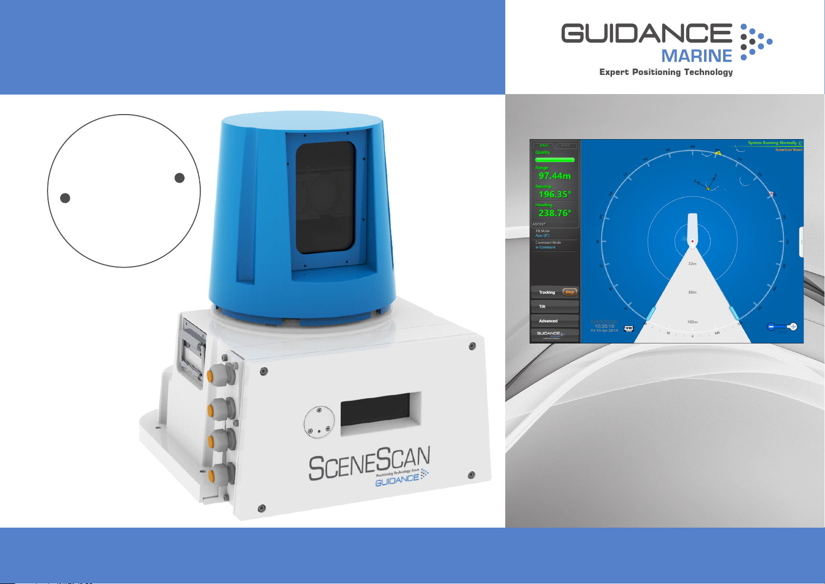
System Overview
The SceneScan System is a high accuracy rotating laser Sensor that provides positional
information to allow automated approach and/or station keeping relative to a structure or
vessel. It is designed to be semi-portable and straightforward to operate.
Its key elements are:
The SceneScan Sensor: The marine grade SceneScan Sensor is mounted on the
•
vessel (typically on the wheelhouse) as required. The SceneScan Sensor emits eye-safe
infrared light and detects the reections received back from one or more designated
structures or vessels.
The SceneScan Client Software: There are two key pieces of software:
•
The SceneScan Service Interface: The SceneScan Service Interface is used
•
for system installation and maintenance.
The SceneScan Dashboard: The SceneScan Dashboard generates a visual
•
representation of the scene detected by the SceneScan Sensor. It gives the
DP Operator control of the system and the data stream being fed to the DP
system.
Both pieces of software run under Windows™ on a Type 3 Marine Processor or other
computer providing the minimum system requirements (See page 55).
The SceneScan system operates dierently to other local position reference systems in that
it does not require any type of target to be placed on the asset that is being approached or
used for station keeping.
It scans the vessel or structure and produces a map. This map is compared to the current
scan by the SceneScan Sensor navigation algorithm, which is used to track a local position.
l
7
Page 8
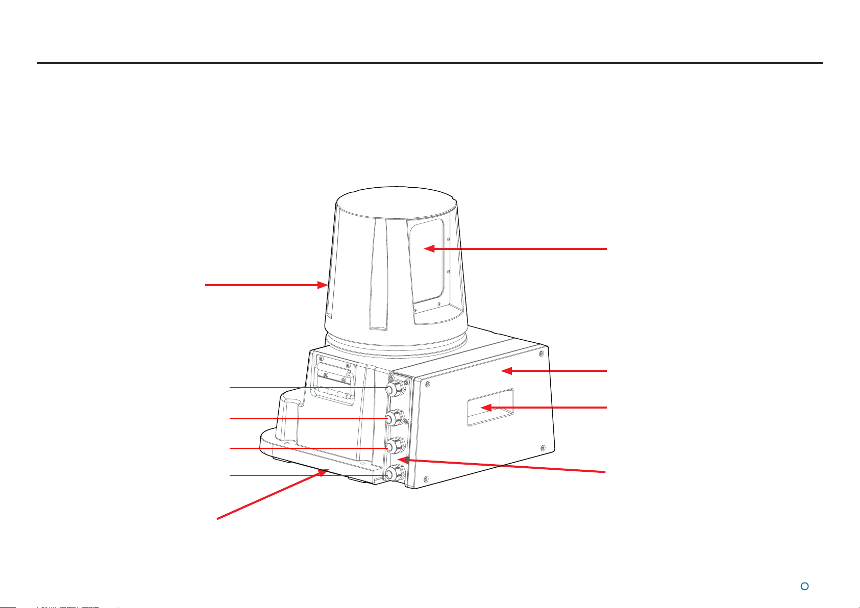
SceneScan Sensor Part Names
The diagram below shows the key parts of the Sensor unit and the various names that are
used throughout this guide:
Rotor
Optical Window
Power
DP Feed 2
DP Feed 1
Client Data
Base Plate
Access Plate
Sensor Information
Display
Cable Gland Plate
l
8
Page 9

Getting Started
This section contains the following pages:
Start Up and Shut Down (page 10)
•
Targetless Tracking (page 11)
•
Screen Layout (page 13)
•
Tracking Information Quality (page 19)
•
Display Settings (page 20)
•
Vessel Orientation (page 22)
•
l
9
Page 10
Start Up and Shut Down
Start Up
To Start SceneScan Dashboard
1. Ensure that the SceneScan Sensor is powered on.
2. Double-click on the SceneScan Dashboard icon.
(Or run the SceneScan Dashboard from
Start > All Programs > Guidance Marine Ltd >
SceneScan > SceneScan Dashboard).
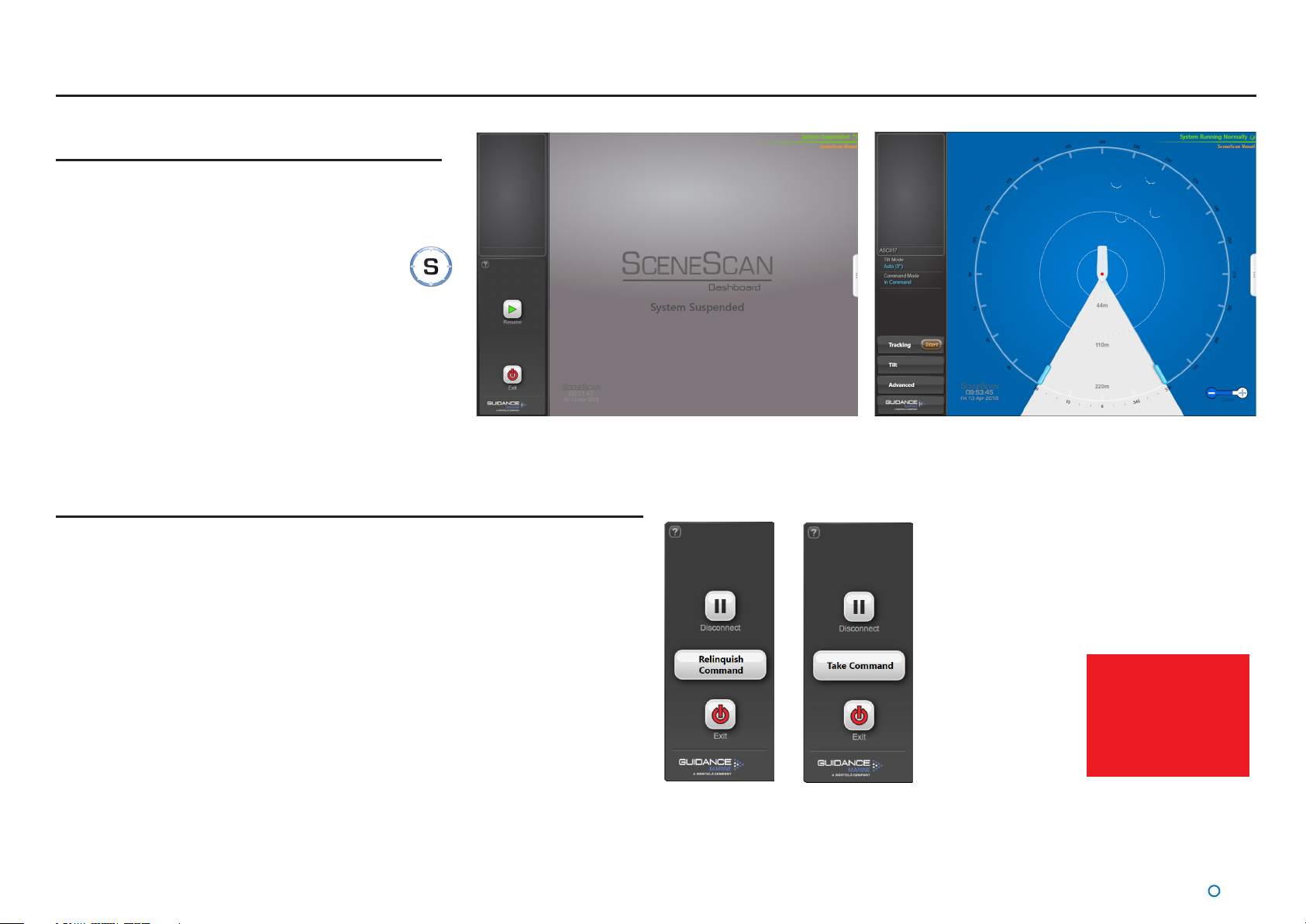
3. The Dashboard display screen will appear.
If the Sensor is currently suspended, the main part of the
screen will be greyed out. Click on the Resume button
in the side bar in order for the Sensor to begin scanning
and for the results to be displayed on the screen. If the
Sensor was already scanning, then the current scene
will be displayed.
Shut Down
Dashboard screen with Sensor suspended Dashboard screen with Sensor scanning
To Suspend, Exit or Disconnect
1. Click on the Guidance button in the lower left corner of the screen.
This will reveal buttons in the side bar as follows: (see right).
Suspend - Places the Sensor into a ‘sleep mode’. The rotor ceases spinning and the
•
scanner tilt returns to a xed state. The unit can be returned to full operation via a
Resume command from the Dashboard. This mode is suitable for use when travelling
between locations.
Disconnect - Ceases communications between the Dashboard and Sensor and
•
causes the main part of the screen to be greyed out. Does not cause the Sensor to stop
spinning or tracking the scene.
Suspend And Exit - Places the Sensor into the same ‘sleep mode’ as the suspend
•
command (discussed above) and also closes the SceneScan Dashboard program.
Exit - Closes down the Dashboard without aecting the Sensor.
•
Dashboard
In Command
Dashboard
Monitoring
See Multi-Dashboard
SceneScan Systems
(page 31) for
information on In
Command/Monitoring
functionality.
l
10
Page 11
Targetless Tracking
Overview of Targetless Tracking
Traditional relative positioning Sensors rely on placing targets on the structure or vessel
which the Sensor then detects and can report a position relative to. SceneScan removes
the requirement to place targets into the scene and instead provides tracking information
relative to natural or man-made structures within the Sensor eld of view. It achieves this
by matching its current observation of the scene against previous observations of the same
scene, in order to determine the motion of the Sensor between observations.
In order to maximise the performance of this approach, the Sensor rst calculates the most
reliable and informative section of the scene to track o. This step is called tilt optimisation,
and involves the Sensor scanning through various sections of the scene to work out which
tilt angle to track at.
Once a suitable section has been selected the system starts tracking and reporting the
position of the Sensor within the scene. As the Sensor moves and the view of the scene
changes, the Sensor will automatically update its model of the scene while tracking without
any need for user intervention.
Blanking Zones
Warning: Before starting tracking it is critical that Blanking Zones have been
!
correctly congured to mask out regions of the scene that we do not wish to
track.
Two types of blanking zone can be congured on a SceneScan system:
Fixed Blanking Zones – These can be exclusively congured using the SceneScan
•
Service Interface. Fixed blanking zones are the Vessel Blanking Zone (Vessel
Parameters) and the Static Blanking Zones.
Operating Blanking Zones – These can be amended in the Dashboard when the
•
system is running, even during tracking. Operating blanking zones are the Dynamic
Blanking Zone and the Minimum Range Filter.
For information on how to set Blanking Zones see the following sections:
Operating Blanking Zones on page 24
•
Vessel Parameters on page 62
•
Static Blanking Zones on page 65
•
l
11
Page 12

Targetless Tracking (Continued)
Tracking Overview
Start Tracking
Once Blanking Zones have been congured the operator can command the Sensor to start
tracking.
SceneScan Tracking is inuenced by the operator’s choice of tilt mode (see the Scanner Tilt
Controls section on page 25 for further information):
Auto - When starting tracking, the scanner will automatically “sweep” through a
•
range of angles to determine the most stable scene for tracking purposes.
Manual - This mode is used to manually tilt the optics to point at the desired part of the
•
scene. When starting tracking, the scanner will use the currently selected angle and no
“sweep” will be performed.
Once a suitable tilt angle has been chosen tracking will start and the scanner tilt angle will
automatically adjust as the range to the asset changes. This is to ensure that the same part
of the scene is used throughout the tracking session.
Scene Reference Point
Once the Sensor has started tracking, it will start reporting its position relative to the Scene
Reference Point.
By default SceneScan will select the centre of the tracked scene for the scene reference
point, with a heading of 0°.
This behaviour should be sucient for most users. However users are also able to edit the
Scene Reference Point, altering both its position and heading. This might be done to align
to the heading of a tracked vessel, or to position oneself against the edge of a platform or
quayside.
Enabling DP Output
Once tracking, the Dashboard will display tracking and scene data, but the Sensor will not
output a DP feed. The reason for this is to allow the operator to review the detected scene,
and to set a Scene Reference Point of their choice before enabling DP Feed output.
When the operator is happy with the tracking data displayed on the Dashboard the DP
output can be enabled and the Sensor will start to report valid position telegrams to the DP
system.
Warning: Changing the Scene Reference Point will disable the DP Feed. This is
done because altering the point can dramatically alter the output from the DP
!
Feeds. The DP Feeds must be re-enabled by following the below procedure.
l
12
Page 13
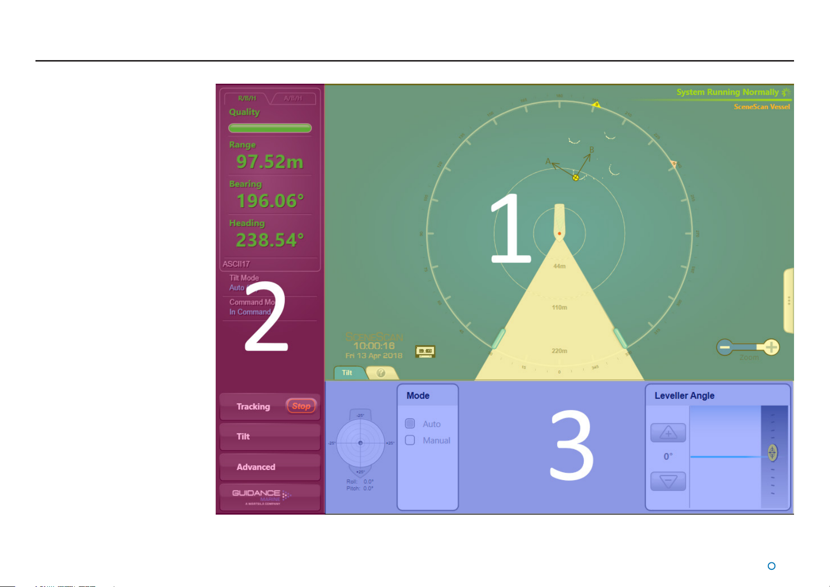
Screen Layout
The SceneScan Dashboard screen
is split into three distinct sections,
these are:
1. Main Screen and Bird's
•
Eye View (BEV) (see page
14)
2. Side Bar (see page 16)
•
3. Menu Pane (see page
•
18)
l
13
Page 14
Screen Layout (Continued)
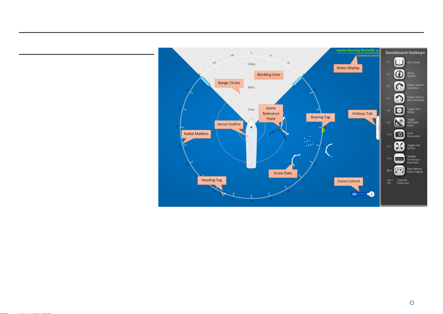
Main Screen and Bird's Eye View (BEV)
The circular BEV shows the observable scene and Scene
Reference Point relative to the Sensor and vessel.
The Figure on the right labels elements on the BEV and its
periphery.
Vessel Outline
The Vessel Outline in the centre of the BEV represents the
ship on which the SceneScan system is located, and the red
dot denotes the SceneScan Sensor. The rotating fan-shaped
symbol represents the laser beam emitted by the rotor as it
turns.
The whole BEV can be rotated in steps of 90° to allow for
dierent positions of the monitor. The size and shape of the
vessel outline and the position of the Sensor’s red dot within it
can be congured using the SceneScan Service Interface.
Blanking Zone
The Blanking Zone is an area dened by the user in order
to blank-out parts of the scene that should not be used for
tracking. During each revolution of the Sensor, when the rotor
enters this sector the laser stops pulsing. The Blanking Zone is
adjusted to suit the current operating conditions.
Range Circles
The Range Circles are a visual guide that help to show the
distances between the Sensor vessel and the detected
reections. Distances are given in metres from the centre of
the Sensor.
Radial Markers
Around the circumference of the BEV are marked angles in
degrees, clockwise from the bow of the vessel.
l
14
Page 15

Screen Layout (Continued)
Scene Data
The Scene Data shows the scene detected by the SceneScan Sensor.
Note: The Scene Data can be constrained to a traditional circular BEV, or expanded to ll
the central area using the Toggle BEV Shape button on the Hotkeys Tab, or by pressing
F8.
Scene Reference Point
The Scene Reference Point shows the point within the scene about which SceneScan is
tracking.
Bearing and Heading Tags
The bearing tag and the heading tag are displayed when tracking is in progress, to indicate
the target’s bearing and the vessel heading on the Radial Marker.
Data Logging Indicator
This symbol is displayed when data is being logged to disk.
Zoom Control
Allows a user to zoom in (+) and zoom out (-) of the BEV. Click on the left-hand side of the
control (marked '-') to zoom out of the display and on the right-hand side ('+') to zoom in.
Hotkeys Tab
The Hotkeys Tab is located on the right hand edge of the main pane. Clicking on the tab will
open the Hotkeys Menu.
System Status
This consists of two elds:
Primary
The primary status display is positioned in the upper-right corner of the main pane. It
indicates the current status of the system, for example System Running Normally or System
Suspended.
Secondary
The secondary status display is positioned in the lower-right corner of the main pane. It
displays a ashing message for a number of seconds in order to conrm an action taken
by the user. It can also display a persistent, static message if there is a communications
problem.
l
15
Page 16
Screen Layout (Continued)
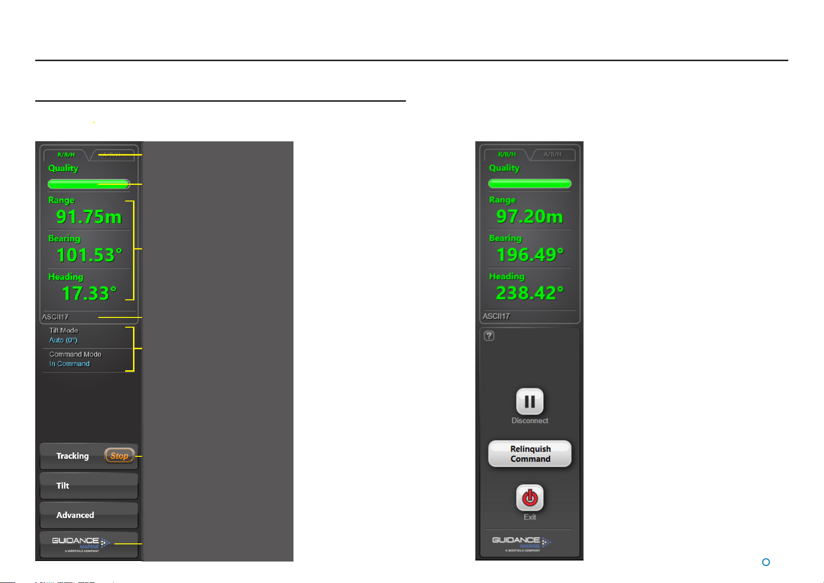
Side Bar
The Side Bar, the black pane on the left of the BEV, contains control and display
components in addition to the coordinates panel.
Toggle Coordinate Type
Signal Quality
Coordinate Data
DP Message Format
Current Tilt Mode
and Command Mode
After pressing the
Guidance button:
Start/Stop Tracking Button
(It is always visible for SceneScan)
Guidance Button
l
16
Page 17
Screen Layout (Continued)
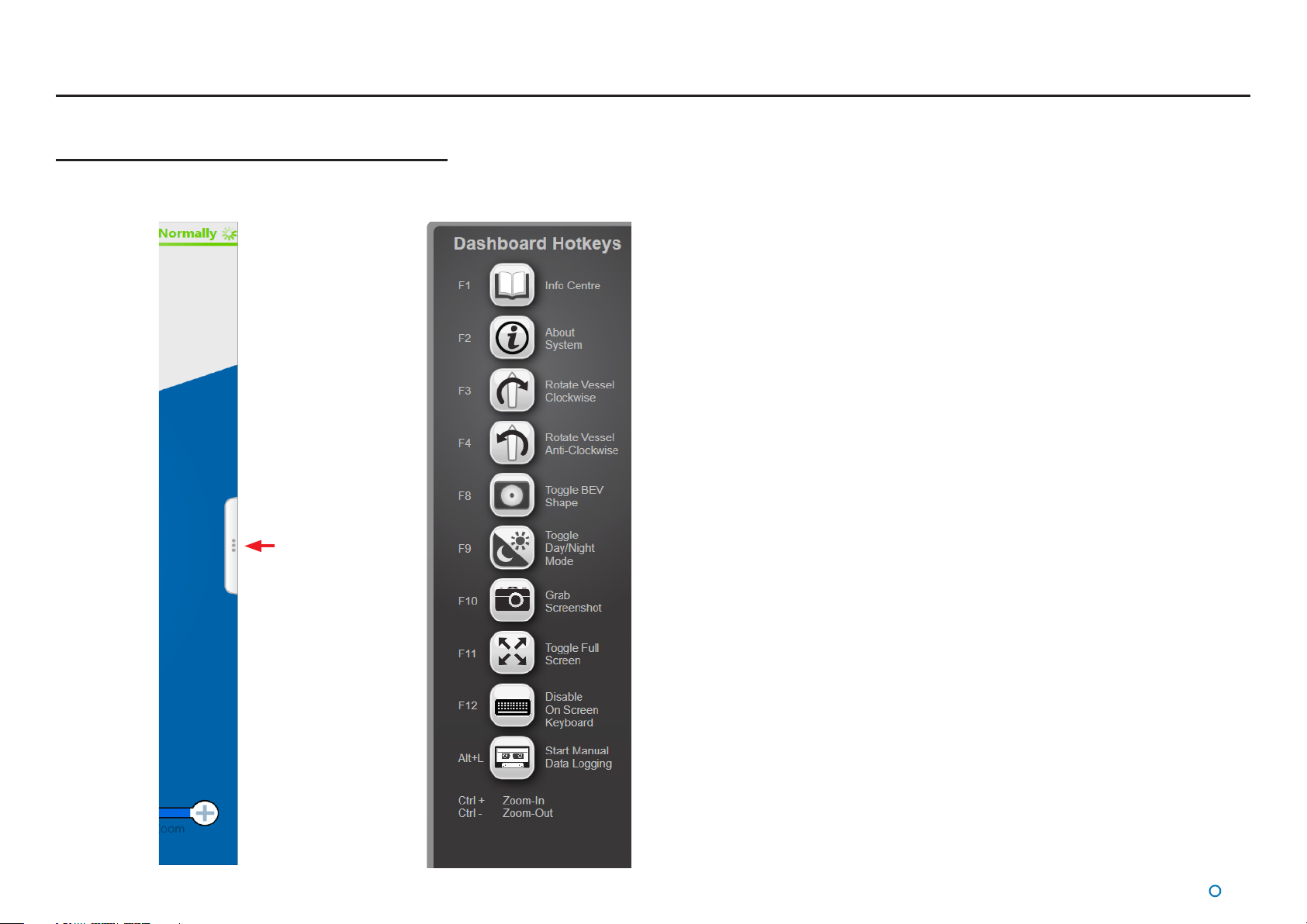
Hotkey Buttons
Selecting the Hotkeys tab on the right-hand side of the main
screen activates the Dashboard Hotkeys menu.
The following keys - and the corresponding buttons on the Dashboard Hotkeys menu - act as
shortcuts to application functions.
F1 Display Help Menu
F2 Toggle between the About System pane and the BEV display
F3 Rotates the Vessel Clockwise
F4 Rotates the Vessel Anti-Clockwise
F8 Toggle between displaying a traditional circular BEV or Full Scene mode
F9 Toggle between the day view and night view
F10 Capture a screenshot of the Dashboard interface and save it to disk
F11 Toggle between normal window layout and full screen layout
F12 Toggle between enabling and disabling the on-screen keyboard
Hotkeys Tab
Alt+L Start Manual Data Logging (available when no tracking operation is in progress):
Starts data logging and changes the button to Stop Data Logging
Ctrl + Zoom-In
Ctrl - Zoom-Out
Esc When in operation conrmation mode, cancel the current operation request
Enter When in operation conrmation mode, conrm the current operation request
l
17
Page 18
Screen Layout (Continued)
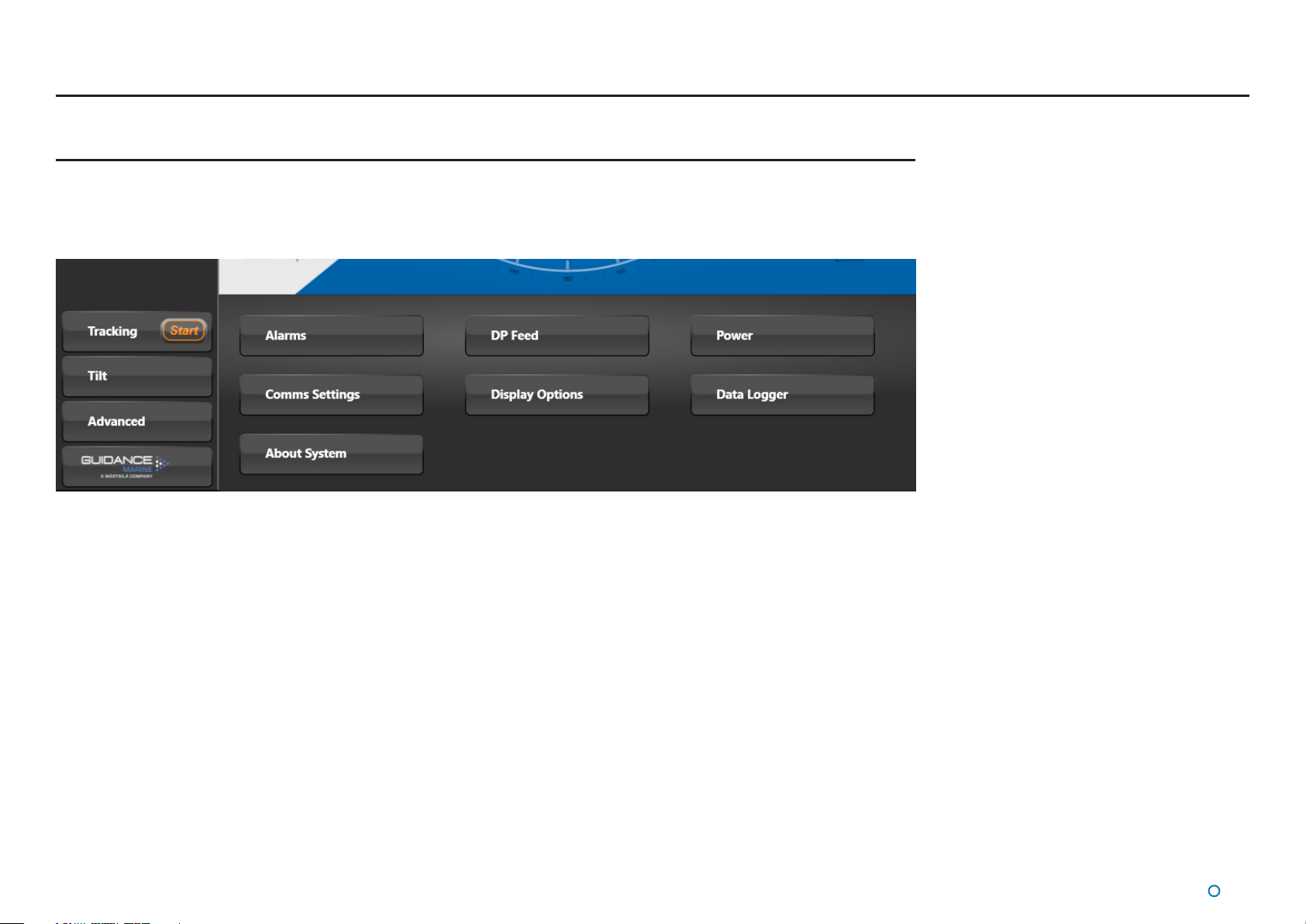
Menu Pane
The Menu Pane, located across the bottom of the SceneScan Dashboard Screen, is not always visible. It appears when one of the
Tracking, Tilt or Advanced buttons near the foot of the Side Bar are pressed, which causes the Bird's Eye View (BEV) to contract
towards the top of the screen. Clicking the same button for a second time causes the Menu Pane to disappear and the BEV to be
restored to full size.
l
18
Page 19
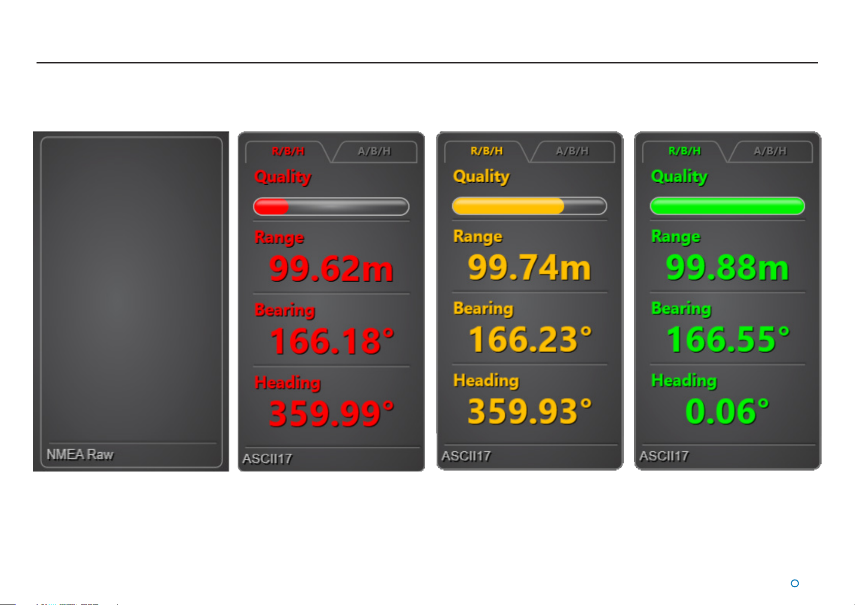
Tracking Information Quality
Once tracking is under way the Data Quality Bar indicates the level of condence the system has in the quality of the scene data that is being acquired. The greater the size of the lled
portion of the Data Quality Bar, the greater the level of condence in the information.
The colour of the Data Quality Bar and positional data also reects the level of condence: RED, YELLOW or GREEN, with GREEN meaning highest condence.
When tracking, the Data Quality Bar and positional data disappear and are replaced with a warning message if the system loses track of the scene.
l
19
Page 20
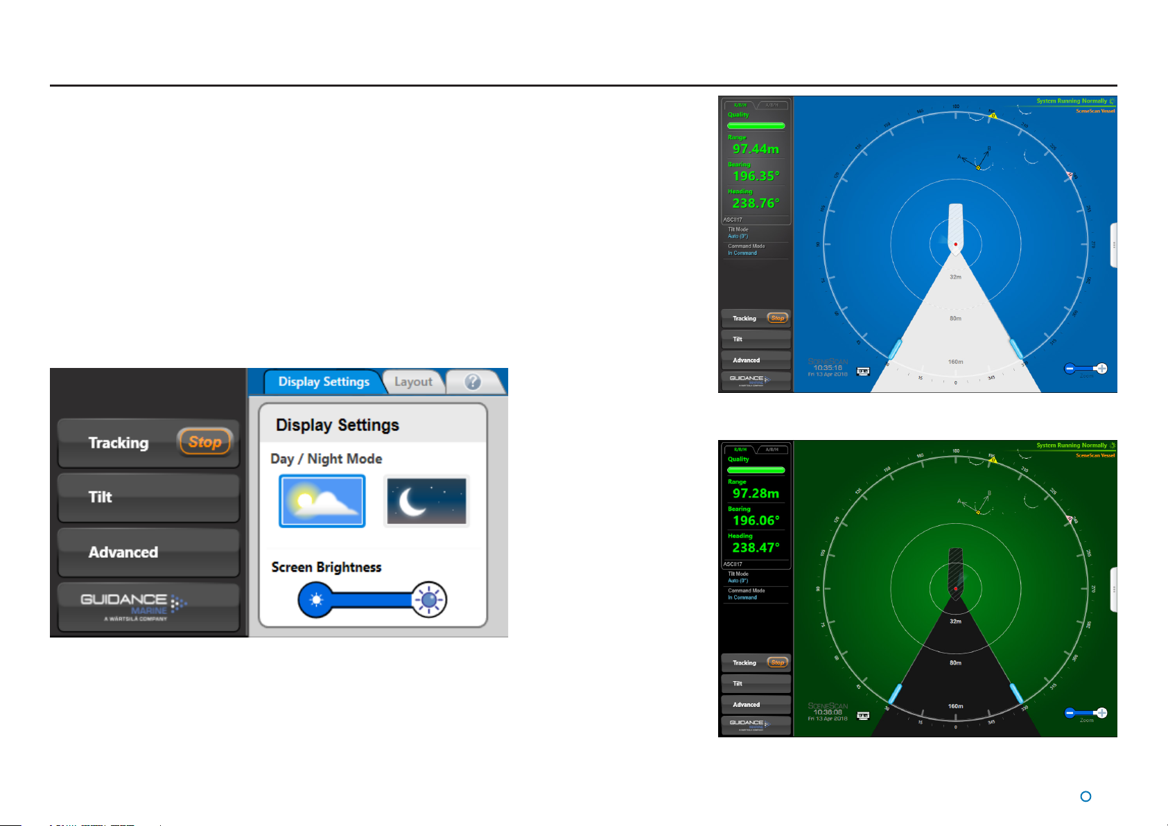
Display Settings
To provide ample visibility during daytime operation and to limit glare during night shifts,
SceneScan Dashboard oers two display settings: Day Mode and Night Mode. In either
mode the brightness can be further adjusted by the Screen Brightness control.
To change day/night mode and adjust brightness:
1. Navigate to Advanced > Display Options > Display Settings.
2. Click on one of the Day / Night Mode symbols.
3. Click on the left side of the Screen Brightness control to dim the screen and on the
right to make it brighter.
Alternatively, to toggle between day and night mode, use the keyboard shortcut F9 or the
Toggle Day/Night Mode button in the Dashboard Hotkeys panel.
Day Mode
Night Mode
l
20
Page 21

Display Settings (Continued)
The central BEV can be toggled between a traditional circular BEV, and a full scene mode.
Press F8 to toggle modes, or use the Toggle BEV Shape hotkey. The latter is useful when
viewing complex scenes such as harbours.
The BEV can be further expanded to a full screen mode by pressing F11, or using the
Toggle Full Screen hotkey
This mode maximises the space available for tracking. Whilst this removes the Side Bar from
view, it can be restored by pressing F11 again, or clicking the Tab along the left edge of the
screen.
l
21
Page 22
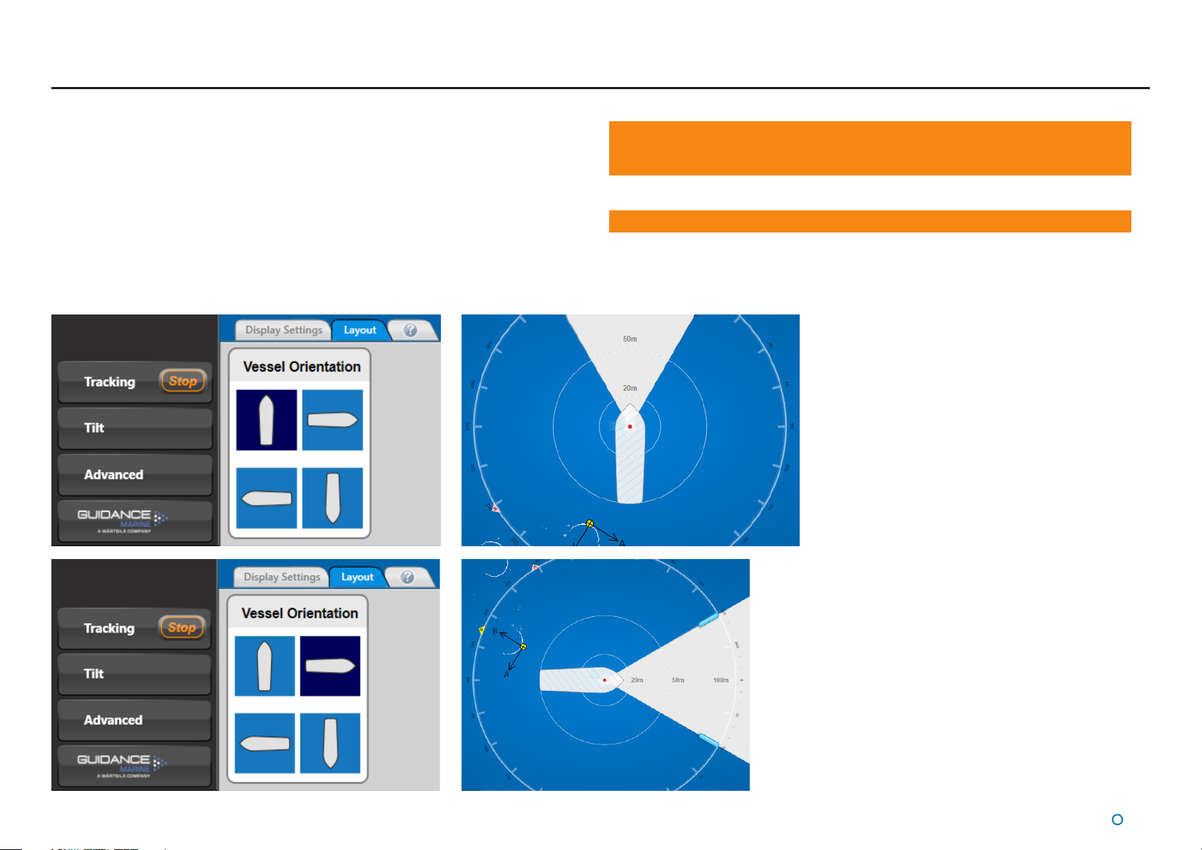
Vessel Orientation
SceneScan Dashboard supports four dierent layouts of the Bird’s Eye View so that the
operator can choose the one which best represents the vessel’s surroundings.
To set Vessel Orientation
1. Navigate to Advanced > Display Options > Layout.
2. Click on the vessel outline that points in the required direction.
Note: Changes made to the vessel orientation using the Dashboard are temporary
and will revert back to the default setting when the Dashboard is restarted� The
default orientation can by changed from within the SceneScan Service Interface�
Note: This is a Dashboard display function only and will not affect the DP output�
l
22
Page 23

Tracking Basics
This section contains the following pages:
Dynamic Blanking Zone (page 24)
•
Scanner Tilt Controls (page 25)
•
Tracking (page 26)
•
Positional Display Modes (page 29)
•
l
23
Page 24
Operating Blanking Zones
Dynamic Blanking Zone
The Dynamic Blanking Zone is used to mask a segment of the scan rotation. When the
scanner passes through the dynamic blanking zone, the laser is switched o to prevent any
unwanted reections.
N.B. Even if the Sensor has a clear 360° view, there must be a dynamic blanking zone of
at least 23°. The user interface will not allow smaller blanking zones.
Generally the dynamic blanking zone will not need to be changed. However, there may be
occasions when it is necessary to adjust the dynamic blanking zone, for example to mask
out another vessel in the Sensor eld of view..
Note: Up to four additional static blanking zones can be congured from within the
SceneScan Service Interface. These are used to mask segments of the scan rotation that
are obscured by the vessel’s superstructure. See the Static Blanking Zones section on page
64 for further information.
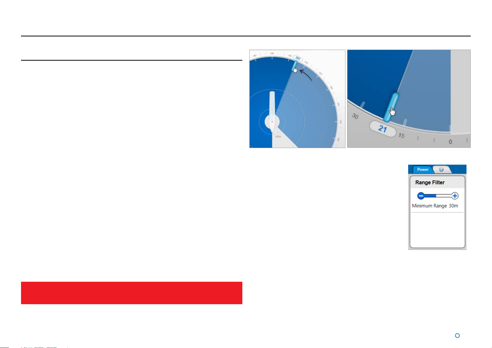
Setting the Dynamic Blanking Zone
The start and end of the zone can be set to any positions around the circle to the nearest
degree, subject to the minimum and maximum sizes of the zone (see red box below).
To dene the Dynamic Blanking Zone
The Dashboard needs to be in Command Mode to make changes to the dynamic blanking
zone.
1. Click one of the dynamic blanking zone handles and, holding down the left mouse
button, drag to the desired position. Alternatively - on a touchscreen - touch and drag.
As the handle is moved, its current position (in degrees clockwise from the vessel bow)
is displayed in blue numerals outside the perimeter of the circle.
2. If required, drag the second zone handle in the same way.
3. The Apply-Cancel buttons will have popped up after step 1. Click on the Apply button
to set the dynamic blanking zone, or on Cancel to restore the dynamic blanking zone to
its previous state.
The Dynamic Blanking Zone must cover at least 23° but no more than 337°. The
user interface will not allow larger blanking zones. It is not possible to change the
blanking zone when in full screen mode.
Range Filters
The Range Filters function on the Power menu allows
the user to set minimum range. Any objects at a shorter
range than the range threshold will no longer be visible
to the Sensor and so will be excluded from tracking. This
mechanism is useful when a structure/vessel other than that
being used for tracking cannot be eliminated by means of the
dynamic blanking zone function alone. It can be used at any
time, even during tracking.
The range threshold can be adjusted between 1 and 70
metres by clicking on the end of the lter bar marked ‘+’ or ‘-’
as required. A corresponding exclusion zone is shown in the
centre of the BEV.
l
24
Page 25
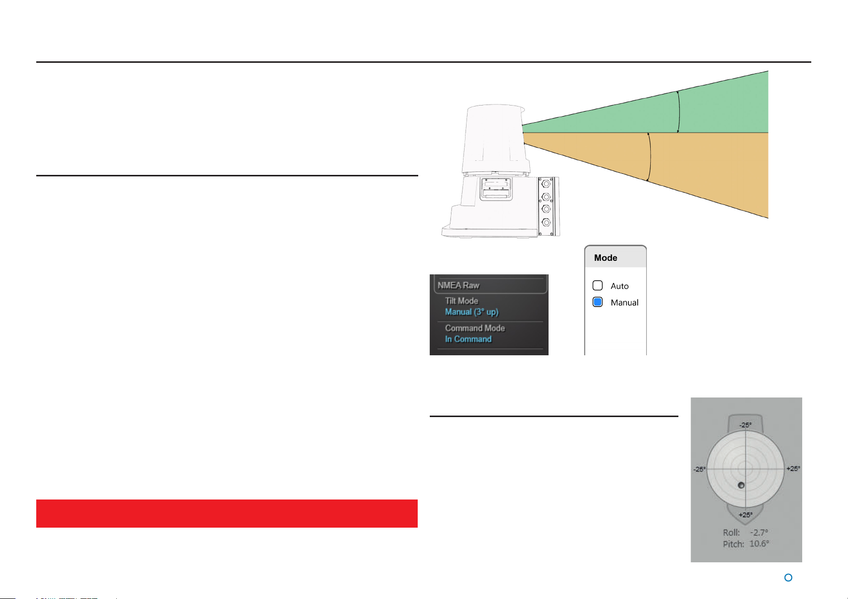
Scanner Tilt Controls
The scanner tilt mechanism automatically compensates for the pitch and roll of the vessel
caused by wave motion.
Motion Sensors and a tilting optics mechanism ensure that the scanning optics remain at
the correct level to see the scene.
16° Scanner Tilt
Scanner Tilt Modes
The scanner can be operated in either of the following tilt modes:
Auto - When starting tracking, the scanner will automatically “sweep” through a range of
•
angles to determine the most stable scene for tracking purposes.
Manual - This mode is used to manually tilt the optics to point at the scene. For
•
example, when station-keeping close to a platform where the superstructure is high up
and the SceneScan beam must be tilted upwards. When starting tracking, the scanner
will initially use the currently selected angle. No “sweep” will be performed. Manual Tilt
can also be used to visually survey the scene around the vessel without tracking.
Once a suitable tilt angle has been chosen tracking will start and the scanner tilt angle will
automatically adjust as the range to the asset changes. This is to ensure that the same part
of the scene is used throughout the tracking session.
When the Sensor is rebooted the tilt mode defaults to Auto.
The current tilt mode and leveller angle are displayed in the ‘Tilt Mode’ section of the Side
Bar.
To change the scanner tilt mode and leveller angle
1. Click on the Tilt button in the Side Bar.
2. Select the required mode and click on the Apply button to conrm.
3. Click on the +/- buttons to adjust the angle.
4. Click on the Apply button to conrm your changes.
Once the scanner starts tracking, it is not possible to change the tilt mode or leveller
angle
Sidebar Tilt Mode section
Tilt Mode Selection
Spirit Level
The Spirit Level control, on the left hand side of the Tilt
pane, displays the roll and pitch of the vessel as measured
by the Vertical Reference Unit within SceneScan. The
graphical display represents the roll and pitch angles in the
same manner as a bull’s eye spirit level. The current values
are displayed in text at the bottom of the control. A ship
outline is shown in the background to indicate orientation
relative to the vessel.
20° Scanner Tilt
l
25
Page 26

Tracking
To Start Tracking
1. Ensure that the Dashboard is In Command (see
Command Mode).
2. Press the Start Tracking button.
3. Press Apply on the Apply/Cancel pop-up.
Tilt Optimisation will start. The angle chosen will depend upon the
current mode:
Auto Tilt - The Sensor will sweep through all possible tilt angles
•
to determine the optimum angle for the scene tracking. The left
pane of the dashboard will show the progress of this operation.
Note that the Sensor may not nd a viable scene for
tracking. This can occur (for example) when in open water.
In this scenario the Sensor will continue Tilt Optimisation
by repeating the sweep process indenitely until a suitable
/ adequate scene is found. This process can be halted by
Stopping Tracking (see below).
Manual Tilt - The Sensor will use the current tilt angle for tracking.
•
Tracking will start once a tilt angle has been selected by the Sensor in Auto Tilt mode,
otherwise the operator / user selects the tilt angle.
To Stop Tracking
While tracking is in progress, a Stop button is nestled
within the Tracking button. Click on the Stop button to
stop tracking.
l
26
Page 27

Tracking (Continued)
Adjusting the Scene Reference Point
Scene Reference Point
This is the point within the scene that SceneScan will report its position relative to. By
default SceneScan will select the centre of the tracked scene as its Scene Reference
Point, with a heading of 0°.
This behaviour should be sucient for most users. However, users are also able to edit
the Scene Reference Point, altering both its position and heading. This might be done
to align to the heading of a tracked vessel, or to position oneself against the edge of a
platform or quayside.
To Edit the Scene Reference Point:
1. Ensure that the Dashboard is In Command (see In Command Mode on page 33)
and is Tracking. It does not matter whether DP Feed is enabled or not.
2. Press the Tracking button to bring up the Tracking Menu.
3. Press the Edit Tracking button.
4. Now the Scene Reference Point can be edited as follows:
1. Left Click on the scene with the mouse to move the reference point to the
clicked location. If Snap To Scene is selected then clicking the scene will
move the reference point to the closest point of Scene Data. This is useful
when trying to align with the edge of a structure.
2. Right Click + Drag on the scene with the mouse to rotate the reference
point, altering its heading.
3. Select Rotate to change the mouse behaviour such that Left Click + Drag
now rotates the reference point. This is useful for touch screens.
4. Use the Align Heading control on the Tracking Menu to precisely control the
heading.
Note that Edits are not live - changes made will only take eect when the “Apply” button
is pressed. The “Cancel” button will undo any pending changes.
Warning: Changing the Scene Reference Point will disable the DP Feed. This is
!
done because changing the reference point can dramatically alter the output
from the DP Feed. The DP Feed must be re-enabled by following the below
procedure.
Note that pressing the Reset button at any point during the edit will undo your
changes without Cancelling your Edit. In addition, the zoom controls can still be
5. Once you are done, press Apply on the Apply/Cancel pop-up.
used to alter the zoom level of the central BEV while selecting the reference point.
l
27
Page 28

Tracking (Continued)
Enabling DP Output
Once tracking, the dashboard will display tracking and scene data, but
the Sensor will not have the DP Feed enabled. The reason for this is to
allow the operator to review the detected scene, and to set a Scene
Reference Point of their choice before enabling DP Feeds.
To Enable the DP Feed:
1. Ensure that the Dashboard is In Command (see Command Mode).
2. Press the Enable DP Feed button.
3. Press “Apply” on the Apply/Cancel pop-up.
The DP Feed will now be enabled, and the dashboard will change to
indicate that tracking is fully enabled.
Tracking Lost
If the SceneScan loses track then the following message will be
displayed in the coordinates pane:
At this point the operator will need to stop and restart tracking.
Manual Tilt Mode
It is highly recommended that Auto tilt mode is used to start tracking when using
SceneScan. However, if a situation is encountered where tracking performance is
unacceptable when using Auto tilt mode then the option is available to manually select a tilt
angle.
Here are some general guidelines to follow when using Manual tilt mode:
1. Try to select regions of the scene that have a high level of vertical consistency.
2. If the vessel will be maneuvering around the structure then consider whether structure
on dierent sides of the structure are also vertically consistent.
3. Watch the BEV to see how consistent the image of the structure is before starting
tracking. If the scene is changing dramatically then tracking is unlikely to be stable and a
dierent tilt angle should be chosen.
4. Small tilt angles will generally provide better tracking performance. This is particularly
true when the range to the asset will be changing signicantly during a tracking session.
5. When tracking o a rig, substructure tends to provide more robust tracking performance
than superstructure.
Vertical features visible from
multiple sides of a rig are good
when wanting to transition around
the asset.
Dierent features closely located
at slightly dierent elevations are
oor targets to track o. Protruding
features of the assest are also not
advised to track o.
l
28
Page 29

Positional Display Modes
The relative positions of the SceneScan vessel and the Scene Reference Point can be
expressed either as Range and Bearing values, or as 'A' and 'B' positions on a rectangular
coordinate frame.
The position of the tracked scene can be displayed as Range/Bearing/Heading or A/B/
Heading.
Users can select the required mode by clicking the appropriate tab above the Data Quality
area:
Range, Bearing & Heading
Range, Bearing and Heading (R/B/H) mode displays the distance and the bearing of the
Scene Reference Point from the Sensor. The radial markers around the outside of the BEV
are zeroed in line with the vessel bow and a magenta tag marks the bearing which is the
angle of the target clockwise from the bow.
A purple tag represents the heading, which is the angle of the vessel bow clockwise from
the heading axis.
l
29
Page 30

Positional Display Modes (Continued)
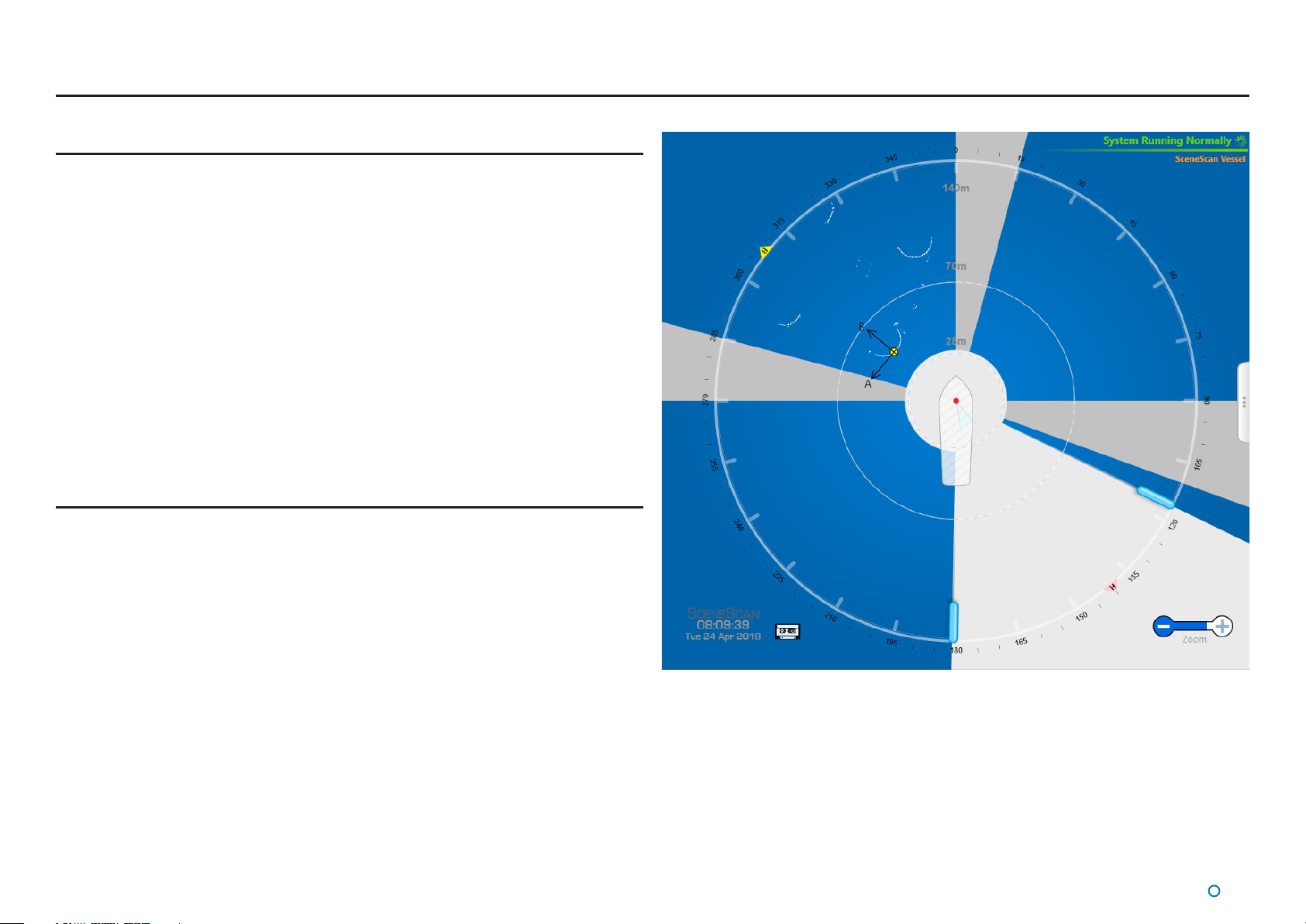
A and B Axes (A Pos and B Pos)
In this mode, the position of the Sensor vessel is expressed in metres from the scene along
A and B axes which have their origin at the Scene Reference Point.
The vessel's relative heading is measured clockwise from the A axis.
A and B Axes
l
30
Page 31

Multi-Dashboard SceneScan Systems
This section contains the following pages:
SceneScan Dashboard - Monitoring Mode (page 32)
•
SceneScan Dashboard - In Command Mode (see page 33)
•
l
31
Page 32

SceneScan Dashboard - Monitoring Mode
SceneScan supports multiple Dashboards running simultaneously on the same system.
No more than one of these can be in Command mode at any given time; the others are in
Monitoring mode.
When the Dashboard is running in Monitoring mode, the controls relating to the Dashboard
itself will be active, but those relating to the SceneScan Sensor will be disabled. A
Monitoring Dashboard displays the same scene as the In Command Dashboard. It cannot
initiate or stop tracking operations, nor alter the power control, nor tilt settings.
Examples of inactive controls in Monitoring Mode
To switch a Dashboard from In Command mode to Monitoring mode:
1. Click on the Guidance button.
2. Click on the Relinquish Command button.
l
32
Page 33

SceneScan Dashboard - In Command Mode
When the SceneScan Dashboard is running in Command mode all control functions are
available. Any changes made to the tracking or Sensor-related settings at the In Command
Dashboard will be visible on the screens of the Monitoring Dashboards. On the other hand,
display options such as Screen Brightness or Zoom level can be set dierently on each
individual Dashboard, whether it is Monitoring or In Command.
When the In Command Dashboard is used to suspend the SceneScan Sensor, a message
will appear on the screens of the Monitoring Dashboards indicating that the system is
suspended. The same message is displayed if a Dashboard is opened whilst the Sensor is
suspended (See Start Up and Shut Down on page 10).
In this state, clicking the Resume button on any Dashboard will automatically put that
Dashboard In Command. Clicking Exit will close that individual Dashboard only.
Whenever the system is running, a Monitoring Dashboard can be promoted to In Command
as shown on the right.
Examples of active controls only available in Command mode
To switch a Dashboard from Monitoring mode to In
Command mode:
1. Click the Guidance button.
2. Click on the Take Command button.
When the Dashboard is
in Command mode, it will
automatically switch to
Monitoring mode when another
Dashboard takes command.
l
33
Page 34

Support Information
This section contains the following pages:
Low Temperature Operation (page 35)
•
Working with Alarms (page 36)
•
Dynamic Positioning Feed (page 37)
•
Network Communications Settings (page 38)
•
Data Logging (page 39)
•
Seial Numbers & Software Versions (page 41)
•
l
34
Page 35

Low Temperature Operation
Introduction
The SceneScan Sensor is a precision electromechanical device with hardware components
that, out of necessity, are mounted in an external position on a vessel’s superstructure. It
is recognised that industrial marine operations may subject these components to harsh
environments, including low temperature.
The SceneScan hardware complies with the requirements of IEC 60068-2-1 and is able
to operate for prolonged periods at temperatures down to – 25°C provided that certain
operating conditions are maintained.
Operating Conditions
The following recommendations are made for low temperature use:
If it is necessary for the system to be switched on after a prolonged period at
•
temperatures below -5°C (and down to – 25°C) the Sensor will warm itself, but will
require 2 hours to reach optimum operating condition.
If the unit is switched on after a period at temperatures between -15 to -25°C it will
•
not communicate with the Dashboard and the rotor will not rotate until the internal
temperature of the base unit rises above -15°C.
When the system is not in use (i.e. un-powered or suspended) the Sensor should be
•
protected by means of a suitable insulating and protective cover to prevent the external
build-up of ice.
Technical Considerations
The SceneScan Sensor uses a sophisticated rotating infrared laser range-nder to
•
accurately measure the distance and bearing to features in the scene. Movement
sensors allow mechanically driven optics to compensate for vessel motion due to wave
action. The internal mechanism may become disabled if it is allowed to cool in a low
temperature environment.
A safety interlock prevents activation of the range-nder laser if the scanner rotor head
•
stops or is prevented from rotating by ice build-up.
l
35
Page 36

Working with Alarms
During operation, the SceneScan system produces an audit trail of event messages. These
range in increasing order of severity from: Information, Warning, and Error to Fatal. As these
alarms are raised, the Dashboard lists them within the Alarms pane.
Click on any alarm to display details about it in the right-hand section of the Alarm pane:
The severity and current state of an alarm are reected in its colour and shape:
Information—grey symbols
•
Warning—orange symbols
•
Error and Fatal—red symbols
•
The ‘Play’ symbol indicates that an alarm condition is persisting. These are known as Active
alarms. An alarm in this state will show a Start time but not a Stop time.
The ‘Stop’ symbol means that the alarm condition no longer exists, i.e. it has Stopped,
therefore the alarm will show both Start and Stop times.
The ‘Pause’ symbol indicates an instantaneous alarm. In this case, the Start and Stop
times are identical.
When an Error or Fatal alarm is raised, the Advanced button glows red. Once the glowing
Advanced button has been clicked, it will take you to the Alarms pane. If the pane is
closed, the Advanced button returns to its normal grey shading.
Fatal Alarms indicate a serious problem with the SceneScan system. Users should review
the alarm details and follow any recommendations listed. Typically these involve powering
down the Sensor and restarting it, along with restarting the Dashboard. If necessary contact
Support.
Filtering Alarms
A lter is available to suppress the display of particular alarm by severity. By default, the lter
is activated and causes information messages to be hidden.
Click on the Alarm Filter button to toggle between activated and de-activated .
Click on the Filter Selection button to choose which types of alarm are to be ltered out:
Alarm types that are ticked are always displayed in the alarms list; un-selected types are
hidden when the lter is activated.
l
36
Page 37

Dynamic Positioning Feed
The Dynamic Positioning (DP) Feed is the data that SceneScan transmits to the vessel’s
DP system. SceneScan supports several dierent data message formats and it is important
that SceneScan and the DP system are both congured to use matching formats. However,
this cannot be done from the Dashboard; in order to change the SceneScan DP settings,
use the SceneScan Service Interface (see page 66 for the Dynamic Positioning Feed
Configuration and See page 71 for the DP Message Types.
The state of the Sensor’s DP output channel, the message format used and the most recent
data output can be viewed on the Dashboard.
To View DP Feed Details:
1. Click on the Advanced button on the side bar.
2. Click on the DP Feed button on the Menu Pane.
l
37
Page 38

Network Communications Settings
The Comms Settings Menu Pane displays the conguration of communications between
the Dashboard and Sensor. This menu only changes the local dashboard record of the
Sensor IP address. Changing the Sensor's IP address (stored in the connect.ini le) is NOT
possible from the dashboard but IS possible from the SceneScan Service Interface Network
Cong tab 'Sensor on-board network conguration' section (See page 59 for the Network
Communication Settings).
To View the Network Comms Settings:
1. Click on the Advanced button on the sidebar.
2. Click on the Comms Settings button on the Menu Pane.
To Modify the Dashboard’s Record of the Sensor’s IP
Address:
1. Navigate to Advanced > Comms Settings.
2. Click on the Edit button.
3. Modify the IP Address eld as required.
4. Click on Apply to conrm.
l
38
Page 39

Data Logging
Manual data logging button enabled. Manual data logging not active.
During tracking, the system automatically generates a set of operation logs that can be
analysed by a service engineer to diagnose any system faults. Logging can also be started
manually, when the system is not tracking (see below).
When logging is in progress, the following symbol is displayed in the bottom left-hand corner of
the main pane.
Logs can be exported and e-mailed to Guidance Marine (customerservices.uk@
guidance.eu.com) or your DP supplier in the event of a problem.
Starting and Stopping Manual Logging
To start manual logging:
Firstly ensure that the Dashboard is in command (see Dashboard – In Command mode
on page 32) then either:
1. Navigate to Advanced > Data Logger.
2. Click on the Start button.
Or
Press Alt+L.
Or
1. Click on the Hotkeys tab.
2. Click on the Start Manual Data Log button.
To stop manual logging:
Either
1. Navigate to Advanced > Data Logger.
2. Click on the Stop button.
Or
Press Alt+L.
Or
1. Click on the Hotkeys tab.
2. Click on the Stop Manual Data Log button.
Or
Click on the ashing Data Logging Indicator in the top left of the main screen.
Or
Manual logging automatically stops when a Dashboard suspends the sensor or relinquishes
command, or when another Dashboard takes command.
DataLogging with Multiple Dashboards
On a SceneScan system with multiple Dashboards, data logs are written by whichever
Dashboard is in command. If another Dashboard then takes command, data logging ceases
on the Dashboard that is no longer in command and starts automatically on the Dashboard
that takes command.
Exporting Data Logs
The most recent data logs can be exported to a remote drive on the Dashboard computer.
To Export Data Logs:
1. Insert a USB or other removable drive into the Dashboard computer.
2. Select the period for which you wish to export logs
(Last Hour, Last 4 Hours, etc).
3. Select Destination Drive from drop-down list, if not already displayed.
4. Click on Export Data Logs.
Use the Refresh button to update the list of USB drives and the Available Space value.
N.B. In addition to data logs, screenshots from the selected time period and a list of alarms
are also exported.
l
39
Page 40

Data Logging (Continued)
Taking Screenshots
The Grab Screenshot option records every detail of the current screen and stores it at the
same location as the data logs. Up to ten screenshots are held and if a further screenshot
is taken, the oldest of the existing ten is automatically deleted.
To take a screen shot:
Either
1. Click on the Hotkeys tab.
2. Click on Grab Screenshot.
Or
Press the F10 key.
l
40
Page 41

Serial Numbers & Software Versions
Serial numbers and Software Version numbers are used to identify the hardware conguration and product revision of each SceneScan unit. They will be requested by Guidance Marine in
the event of an application service support call to the company.
Product Label
The Part Number and
Serial Number can be
found on the product label
xed to the SceneScan
unit, see below.
SceneScan Sensor
Product Label
Software Version Information
The About tab of the SceneScan Service Interface displays software version
information and the Sensor serial number.
Software Version
Information
SceneScan Sensor
Serial Number
SceneScan
Sensor Part
Number
SceneScan Sensor
Serial Number
l
41
Page 42

Troubleshooting
If you experience problems when installing or using the SceneScan system, please check
through this section for a possible solution. It contains the following pages:
Problems and Possible Remedies (page 43)
•
SceneScan Fuse Information (page 44)
•
If your problem is not listed or you cannot resolve the issue, please contact the system
installer or equipment provider who are trained to assist with installation and operational
problems.
If the problem cannot be resolved by the system installer or equipment provider, please
contact Guidance Marine Limited:
Contact Details
UK Support: +44 116 229 2665
(365 days a year, 08:00 - 20:00 hours UTC)
customerservices.uk@guidance.eu.com
USA Support: +1 504 305-1120
customerservices.us@guidance.eu.com
How to report issues
By reporting issues with enough information it is possible for our customer support engineers to quickly diagnose and solve your diculties. When reporting issues we can give you best advice if you include the following:
A description of what you were trying to do.
•
An indication of whether this was a repeated issue or if it was a single
•
occurrence.
Sensor logs from the time of the issue. Details of how to extract these can be
•
found on page 39
Should the issue cover a period when the system was not tracking then a
•
manual log is very informative. This can be started via either the logging menu,
via the hotkey menu or by pressing Alt+L. See page 39.
If possible a picture of the scene.
•
If possible the name of the asset you are positioning alongside.
•
Asia Support: +65 6734 6365
customerservices.sg@guidance.eu.com
Web: www.guidance.eu.com/customer-support
l
42
Page 43

Problems and Possible Remedies
No communication between SceneScan Dashboard and
the Sensor
The Dashboard screen turns grey, the Primary Status Display reads “Communications
•
Error” “Unable to communicate with the Sensor”. Click the Disconnect button then the
Connect button.
Check the power and client connections to the Sensor.
•
Check that the unit is displaying the current time on the Sensor Information Display. If it
•
is showing any errors then power cycle the Sensor.
Check that the Sensor is displaying the same IP address on the Sensor Information
•
Display as the Dashboard Sensor Comms pane
Rotor does not rotate
Check the temperature of the unit is above -15°C degrees. Below this the rotor is
•
prevented from spinning to protect the Sensor mechanics.
Check that the Dashboard is not showing a ‘Motor Stall’ alarm; if so, suspend and then
•
resume the unit to restart the motor.
The Sensor rotor might be prevented from rotating due to mechanical
•
blockage. Investigate and remove blockage.
Check the Sensor Information Display on the system unit. Ensure that there are no
•
errors displayed. Otherwise power cycle the unit and observe the messages on the
display.
Check for ice build up under the rotor. Remove any ice which may be present.
•
Vessel Blanking Zone
SceneScan applies a blanking zone based on the dimensions of the vessel and position of
the Sensor on the vessel. The following settings are used in the SceneScan Service Interface
to congure the size of the vessel blanking zone:
Vessel Length
•
Vessel Breadth
•
Bow Oset
•
Starboard Oset
•
See section on Vessel parameters for details of these settings.
To test that the vessel blanking zone is correctly congured you should tilt the Sensor optics
downwards the back of the vessel and ensure that no pulses from the vessel structure are
observed outside of the vessel outline in the Dashboard.
System appears to be operational but no scene is
displayed when the Sensor is close enough to a structure
to be able to detect it
Check that the dynamic and static blanking zones are congured correctly.
•
Clean the SceneScan Sensor window.
•
Check whether there are any pulses on the Dashboard Power menu and that the Zoom
•
control on the main screen is set appropriately.
Check that the Tilt controls are set appropriately.
•
Check that the Power controls on the Power menu are set appropriately.
•
Check that the Minimum Range Filter on the Power menu is set appropriately.
•
Check that the Sensor has a clear view of the scene.
•
System tracking but no data is received by the vessel’s
DP system
Check the DP Feed connection from the Sensor.
•
Check that the DP Message Format matches the conguration of the vessel’s DP
•
system.
Check that the Enable DP Output button is not visible on the Dashboard. If it is then
•
press it to enable the DP output.
System operates correctly but in cold weather loses
scene.
Check for condensation or ice on the window of the Sensor. Clean if necessary.
•
l
43
Page 44

SceneScan Fuse Information
The SceneScan system contains two replaceable fuses; one for the Live and the other for
the Neutral. These are located on the connector board as shown below.
Connector Board Fuse
Please refer to SceneScan Sensor connections on page 51 on how
to access the connector board.
To remove a fuse from its housing, t a at-head screwdriver into
the slot in the insert - then push it in and turn it anti-clockwise until
the insert releases and can be pulled out.
Reverse the above procedure to replace the fuse.
Both fuses have the same specication.
Ensure the replacement fuse has the same specication as
the original fuse.
1 GND
1 RX+
1 RX-
1 TX-
1 TX+
Live
Neutral
The fuses should be 20mm anti-surge glass fuses rated for 250V.
The current rating should be determined by the table below.
Voltage Supply 230v 110v
Normal Operation 630mA 630mA
Low temperature operation 1.25A 2A
Normal operation is where the Sensor is operated at -10°C or
above.
When operating at below this temperature internal heaters warm
the unit at start up.
CAUTION: DOUBLE POLE/NEUTRAL FUSING
1 GND
1 RX+
1 RX-
1 TX-
1 TX+
l
44
Page 45

Installing the SceneScan Hardware
This section contains the following pages:
Where to Mount the Sensor (page 46)
•
Sensor Dimensions and Mounting Template (page 47)
•
l
45
Page 46

Where to Mount the Sensor
Sensor Mounting Locations
The SceneScan system is designed for permanent or semi-permanent installation on-board a
vessel. Often, a custom-fabricated plinth is used to provide the optimum height and location
for mounting the SceneScan Sensor.
On all types of vessel the Sensor should be mounted:
With an unobstructed view in the expected direction of the scene (structure or vessel).
•
Well above sea level to prevent swamping or immersion.
•
On a at, rigid, horizontal surface able to support 30kg and receive 4x M8 xing bolts.
•
Allowing for easy access to the connector board and Sensor Information Display.
•
Clear of VHF emergency band antennae, S-band and X-band ship’s radars (5 meter
•
minimum horizontal separation from RF sources (VHF, S and X band) and ideally vertical
separation of one deck).
Clear of likely emissions from exhausts or other particulate sources to reduce the need
•
for cleaning the optical windows.
The eld of view o the vessel should be clear of retroreective material
•
Exhaust emissions contain particulates which will degrade the optics.
The Sensor should be mounted with the Access Cover available for easy maintenance (see
page 9). Any deviation from the centre-line alignment must be corrected in the SceneScan
Service Interface. See the Bearing Oset section on page 61 for further information.
A typical mounting position is above the wheelhouse for a vessel with a
superstructure like that of a platform supply vessel.
l
46
Page 47

Sensor Dimensions and Mounting Template
Sensor Clearance
The exact dimensions of the SceneScan unit’s footprint are shown below.
Additional information shown on the right could be benecial when mounting the SceneScan
unit. Please refer to Document No: 94-0062-4 CyScan Mounting Template to view the
information in larger format.
407
190
4 x
9 THRU
360
405
300
705
Mounting Template
Mount the baseplate horizontally.
Allow 150mm
clearance for
access to the
rotor screws.
150
Allow a Sensor height of 460mm
from the mounting plate, plus an
additional 30mm clearance to
remove the rotor from the shaft.
460
150
150
Allow 150mm
clearance at either side
of the unit for use of
the lifting handles.
47
327
150
857
80
150 150
Ensure a clear
line of sight to the
Display Screen in
the access plate.
857
300
705
Allow 300mm
clearance at the
access plate to
manoeuvre internal
assemblies in/out.
All dimensions in mm
NOT TO SCALE
47
l
Page 48

Installing the Cables
This section contains the following pages:
Cable Specifications (page 49)
•
UPS Specifications (page 50)
•
SceneScan Sensor Connections (page 51)
•
SceneScan Client and DP Feed Connections (page 52)
•
Cable Routing Diagrams (page 53)
•
l
48
Page 49

Cable Specications
The SceneScan system is usually supplied without the cables that are necessary to connect the Sensor to the DP system and the Client Software computer(s). Guidance recommends that
exible multicore cables are used in all applications. Cables should meet the requirements of IEC 60228 Class 2 or Class 5. Cables must be supplied and tted by the installer to match the
particular requirements for each vessel. All cables should be properly secured.
The cable glands will t cables from 7-13mm diameter.
All cables should be
• External marine standard including UV and chemical resistance
• 500V rated voltage
• Diameter 7-13mm
• Operate between -30°C to +70°C.
Note: Data cables should not be run across or next to power cables to avoid signal
interference problems.
Cable Description Guidance Marine Part Numbers m lengths
Ethernet Connection to
Client Software Computer
CAT 5e screened cable (maximum
length 90m).
33-0124-3
Ethernet Cable
Power Cable 3 core power cable
Serial Signal Wiring to DP
System
Refer to the cable routing diagrams on page 53 - 54 to determine which cables you require.
Minimum core shielded data
cable
33-0121-3
3-core power cable
30-0451-3
core shielded data cable
l
49
Page 50

UPS Specications
The power supply to the SceneScan Sensor and the computer(s) running the SceneScan
Service Interface and Dashboard must come directly from a Un-interruptible Power Supply
(UPS), which will also act as the power disconnection point.
The SceneScan system has the following requirements; the UPS system used must meet
these minimum specications:
SceneScan Sensor
The UPS must be Marine Type Approved
•
Input Power = 130W †
•
Voltage Range = 86-264V AC
•
Peak Current draw at 110V = 1.6A
•
Nominal Current draw at 110V = 1.2A RMS
•
Peak Current draw at 230V = 0.7A
•
Nominal Current draw at 230V = 0.6A RMS
•
The SceneScan UPS should be able to run on back-up power for at least the same duration
as that specied for the DP System UPS.
The power cable to the SceneScan Sensor must be rated to withstand the maximum
current output of the UPS.
† Worst case power consumption when operated at -25°C
Type 3 Marine Processor Power Adaptor
Voltage Range = 100-240V
•
Frequency Range = 50-60Hz
•
Peak Current draw = 1.8A
•
Hatteland Panel PC
Voltage Range = 115 & 230V
•
Frequency Range = 50-60Hz
•
Nominal Current draw at 115V = 0.52A RMS
•
Nominal Current draw at 230V = 0.26A RMS
•
The specications given above apply when the UPS is connected to a
SceneScan system only.
l
50
Page 51

SceneScan Sensor Connections
To Connect a Cable to the SceneScan Sensor
1. Remove the 4 screws from the access cover and remove the plate from the Sensor unit
to expose the connector board. (See SceneScan Sensor Part Names on page8).
2. Remove the screw head from the appropriate watertight cable gland. See SceneScan
Sensor Part Names on page8 to identify the correct cable gland.
3. Feed the cable through the screw head and gland.
4. Connect the cable to the correct socket/terminal on the Sensor connector board.
5. When all the connections have been made, replace the access cover and tighten all of
the cable glands to ensure a watertight seal.
Connecting the Power Cable
1. Having fed the cable through the watertight cable gland, Strip 10mm of insulation from
the end of each of the three cable cores.
2. Connect the 3 cores to the appropriate terminals as labelled on the terminal block
(see right).
3. When the connections to the terminal block have been made, use two cable ties to
secure the terminal block and cable together.
4. Plug the terminal block securely into the socket on the connector board as shown on
the right.
Cable ties
Power terminal block with cable cores
connected
Please see page 44 for the fuse recommendations.
Watertight
cable gland
Power terminals on
connector board
Live
Earth
Neutral
To Connect Cables to
Power/Serial Plugs:
Insert Operation
M
Lever-tool (part
number: 190-0003-4)
into slot above
connector-hole in plug.
Whilst holding down
R
lever, insert cable end
into connector-hole.
Release and remove
C
the lever-tool.
1 GND
1 RX+
1 RX-
1 TX-
1 TX+
1 GND
1 RX+
1 RX-
1 TX-
1 TX+
Base of SceneScan with the access cover removed to expose the connector board
51
l
Page 52

SceneScan Client and DP Feed Connections
Connect Ethernet Port 0 to the Marine Processor, Serial Port 1 to DP System 1 and Serial Port 0 to DP system 2.
Congure the serial connections as shown below:
To Connect Cables to
Power/Serial Plugs:
Insert Operation Lever-
M
tool into slot above
connector-hole in
plug.
Whilst holding down
R
lever, insert cable end
into connector-hole.
Release and remove
C
the lever-tool.
19.6mm
4.1mm
10mm
Serial 1
DP
Feed 1
1 GND
2 RX+
3 RX4 TX5 TX+
Note: Either Serial 0 or Serial
1 can be used. The DP feed is
output from both ports.
RS422 Link
9600 baud
8 bits
1 stop bit
No parity
Serial 0
DP
Feed 2
1 GND
2 RX+
3 RX4 TX5 TX+
(Optional)
†Contact Guidance
Marine if
alternative settings
are required.
Note: the Ethernet
and the Serial screen
should be connected
at the Sensor only.
Do not terminate at
both ends.
6.6mm
Connect earth cable
to earthing point.
Default Ethernet Settings:†
IP Address: 192.168.0.86
Subnet Mask:
255.255.255.0
Note: The default IP address
may need to be changed prior
to installation through the
SceneScan Service Interface
software (SSI)
Mains Power
86–264V AC
RS422
Link to DP
System 1
RS422
Link to DP
System 2
Ethernet
Link to
Marine
Processor
Ethernet 1
Ethernet 0
Serial 1
Serial 0
1 GND
1 RX+
1 RX-
1 TX-
1 TX+
1 GND
1 RX+
1 RX-
1 TX-
1 TX+
Power
Fuses
VFD Screen
Service Connections
Power LED
l
52
Page 53

Cable Routing Diagrams
DP Instrument Room
16A
DP System UPS
Bridge
See page 53 for processor and monitor options
SceneScan
Monitor
Monitor Cable
SceneScan Client Computer
Power
Marine Processor
Monitor Power Cable
Emergency Breaker Box
Power Cable
5A
Adaptor
Ethernet
Ethernet Cable
P/N 33-0124-3 (40m)
Mast
Link Cable
SceneScan
Client
DP Feed
Power
SceneScan
Sensor
Connection
Box (Optional)
Note: The Ethernet cable connecting the
SceneScan Sensor to the Type 3 Marine
Processor should not exceed 90 metres
in length.
Please contact Guidance Marine if longer
distances are required.
DP System 1
Interface Cabinet
DP System 2
Interface Cabinet
(Optional)
5A
Sensor Power
Power Cable
P/N 33-0121-3 (40m)
RS-422 Data
Data Cable
P/N 33-0451-3 (40m)
RS-422 Data
(Optional)
Data Cable
P/N 33-0451-3 (40m)
l
53
Page 54

Cable Routing Diagrams (Continued)
Alternative Processor and Monitor Options
Any of the following congurations may be used (see page 53)
KME
Monitor
Monitor Cable
Type 3 Marine Processor
Power
Marine Processor
Power Cable
Monitor Power Cable
Processor:
Type 3 Marine Processor
(Part Number 20-0280)
Monitor: KME 15” Desktop Monitor
(Part Number 20-0115-1)
Note: In the rst two congurations, a Type 3
Marine Processor is used
Adaptor
Ethernet
Cable
Hatteland
Touchscreen
Monitor
Monitor Cable
Type 3 Marine Processor
Power
Marine Processor
Power Cable
Monitor Power Cable
Adaptor
Processor: or
Type 3 Marine Processor
(Part Number 20-0280)
Monitor: Hatteland Marine Touchscreen
Monitor (Part Number 20-0211-4)
Optional brackets: Hatteland Mounting
Bracket (Part Number 24-0259-4)
Hatteland VESA Bracket for Wall or Ceiling
(Part Number 24-0258-4)
Ethernet
Cable
Hatteland
Panel PC
Power Cable
Ethernet
Cable
Processor and Monitor: Hatteland
Panel PC (Integrated PC and Touchscreen
Monitor, Part Number 20-0182-1)
Optional brackets: Hatteland Mounting
Bracket (Part Number 24-0259-4)
Hatteland VESA Bracket for Wall or Ceiling
(Part Number 24-0258-4)
l
54
Page 55

Installing the Control PC
Before setting up the SceneScan client computer(s), refer to the relevant installation sheet(s) for
dimensions and connections information:
For a Type 3 Marine Processor:
94-0465-4 Type 3 Marine Processor and Display Installation Sheet
•
For a Hatteland Panel PC:
94-0466-4 Hatteland Panel PC Installation Sheet
•
The following pages explain how to install and uprgrade the client software:
Installing SceneScan Client Software onto a Computer (page 56)
•
Upgrading the Sensor Software (page 57)
•
l
55
Page 56

Installing SceneScan Client Software onto a Computer
This section explains how to install the SceneScan client software onto computers running
Windows 7 or later. If this Marine Processor has been supplied by Guidance Marine, it
will have been shipped with the client software already installed. If the client PC has not
been supplied by Guidance Marine, then the Guidance Prerequisites must be at least
version 2.2 before installing any client software. With each Guidance sensor, there will
be a USB supplied which includes the Prerequisites. If you are unable to locate this USB
please contact Guidance Marine for instructions on how to acquire and complete the
prerequisites installation. If you are upgrading to a newer version of the SceneScan client
software you can simply install over the old version.
If you are downgrading to an older version of the software you must rst uninstall the
version you have before installing the older version.
To Install the SceneScan Client Software
1. Locate the les SceneScanDashboardSetup.exe and
SceneScanServiceInterfaceSetup.exe on the USB memory stick on which they were
supplied.
2. Double-click on the SceneScanDashboardSetup.exe le.
The Welcome screen is displayed.
3. In order to proceed you must agree to the license conditions and tick the box.
4. Click on the Install button.
5. If required, change any of the Conguration settings from the default values shown (see
below).
6. Click on the OK button
7. Click on the Close button on the SceneScan Dashboard Setup Successful window.
8. Repeat steps 2..4 and 6..7 for SceneScanServiceInterfaceSetup.exe.
Note: The SceneScan
!
Service Interface should
only be installed onto one
computer in the system. The
Dashboard may be installed
onto multiple computers.
Conguration Settings
When installing the SceneScan Dashboard, adjust the following settings or allow to default:
Communications Parameters
Ensure that the Sensor IP address is correctly specied.
In order to run the Dashboard in Emulator Mode, ensure that the Emulator option is
selected.
Logging
The Minimum Free Disk Space (MB) eld denes an approximate amount of disk space
that the Dashboard will leave free when writing log les.
l
56
Page 57

Upgrading the Sensor Software
To Upgrade the Sensor Software:
1. Ensure that the SceneScan Service Interface and Dashboard applications are not
running.
2. Locate the le SceneScan.Installer.Remote.exe on the USB memory stick on which
the SceneScan software was supplied.
3. Double-click on the SceneScan.Installer.Remote.exe le.
4. Enter the Sensor’s IP Address.
5. Click on the OK button. A stream of progress messages is then output, along with any
error messages that may be applicable.
6. After “Installation Complete” is displayed, click on the OK button.
l
57
Page 58

Conguring the SceneScan System
This section contains the following pages:
Using the Service Interface (page 59)
•
Network Communication Settings (page 60)
•
Vessel Parameters (page 62)
•
Static Blanking Zones (page 65)
•
Dynamic Positioning Feed Configuration (page 66)
•
DP Feed Behaviour (page 67)
•
System Parameters (page 69)
•
DP Message Types (page 71)
•
Service Schedule (page 76)
•
SceneScan Installation Checklist (page 77)
•
Index (page 78)
•
Document History (page 80)
•
l
58
Page 59

Using the Service Interface
The SceneScan Service Interface is a tool for conguring the SceneScan system.
To open the SceneScan Service Interface
1. Ensure that the Sensor is powered on and connected to the control computer.
2. Double-click on the SceneScan Service Interface icon:
(Alternatively, run from the Start menu:
Start > All Programs > Guidance Marine Ltd > SceneScan > SceneScan Service
Interface).
Screen Layout of the SceneScan Service Interface
The upper part of the SceneScan Service Interface window contains elds relating to
communications, as follows:
Take Command / Relinquish Command – This button allows the user to toggle the
command mode of the SSI between In Command and Monitoring.
Connect – Replaces the Take Command / Relinquish Command button when the
SceneScan Service Interface is disconnected from the Sensor, allowing re-connection.
Status Display – Indicates the current status of the system, e.g. “System Running
Normally” or “System Suspended”.
Activity Wheel – A green rotating animation when the SceneScan Service Interface is
connected to the Sensor; ‘green and stationary when disconnected’; red and stationary
when there is an error condition.
The remainder of the SceneScan Service Interface screen is occupied by one of several tab
areas.
The Status Tab
The Status tab gives an overview of the operational state of the system; it contains the
following elds and control buttons:
Connected State - Whether the SceneScan Service Interface is “Connected” to the Sensor
or “Disconnected”.
Sensor State - “System Running Normally”, or “System Suspended” when the SSI is
connected, or “System Disconnected”, “Communications Error”, or “System Disconnected
(Fatal Error)” when not connected.
Sensor Address - Ethernet IP address of Sensor.
Suspend / Resume button - Can be used to suspend/resume the sensor when In
Command.
Sensor Type - “SceneScan” if the SceneScan Service Interface is connected to a physical
Sensor, “Emulator” if connected to the SceneScan Emulator application or “Blank” if not yet
connected.
Tracking State - “Not Tracking”, “Starting Tracking” or “ Tracking”.
#Tracked Reectors - Not applicable for SceneScan
Last Time Feedback Received - In hh:mm:ss format; updated once per second regardless
of command mode and blank when disconnected.
Get Service History - Enabled when tracking is not in progress. When clicked, a Browse
For Folder window allows you to choose a storage location. Clicking OK then causes the
service history information to be written to an .xml le in the chosen location. The le, named
ServiceHistory_<Sensor serial number>.xml, can then be sent to Guidance Marine for
analysis as necessary.
Reboot Sensor - Enabled only when In Command and not tracking.
Set Sensor Time - Sets Sensor time to match client PC time. Enabled only when in
command mode and not tracking.
l
59
Page 60

Network Communication Settings
The Network Cong tab of the SceneScan Service Interface is used to view and amend the
SceneScan Service Interface’s denition of its communications link with the Sensor, and it
can be used to recongure the Sensor’s IP address.
To Modify the SceneScan Service Interface’s Communications Settings
1. Click on the Network Cong tab of the SceneScan Service Interface.
2. Click on the Disconnect button if the SceneScan Service Interface is connected to the
Sensor.
3. Click on the Edit button.
4. Alter the settings as required.
5. Click on Apply to save the changes or on Cancel to discard.
To Modify the Sensor’s On-Board Network Conguration
There are two options to modify the network conguration on the Sensor.
Option 1
1. Using the Sensor’s current network conguration, connect to the Sensor by clicking the
Connect button (if the SceneScan Service Interface is disconnected from the Sensor).
2. Click on the Take Command button (if the SceneScan Service Interface is not already In
Command).
3. Under Sensor On-Board Network Conguration click Edit, then enter the desired IP
address
4. Click Apply.
5. You will be prompted to conrm your selection. Click on Yes to conrm.
l
60
Page 61

Network Communication Settings (Continued)
6. You will be prompted with another window once the settings has been successfuly
applied, click OK to reboot the Sensor.
7. Leaving at least 30 seconds after step 7, click OK on the Reboot Request Succeeded
dialog and the Service Interface should be connected to the Sensor.
Option 2
1. Contact Guidance Marine and obtain a new Sensor network conguration le (connect.
ini).
2. Click on the Take Command button (if the SceneScan Service Interface is not already In
Command).
3. Click on Browse.
4. Locate the connect.ini le within the Select a Sensor network conguration le window
and click on Open.
5. Click on Send To Sensor.
6. You will now be prompted to reboot the Sensor so that the new conguration can be
applied. Click on Yes in the File Sent Successfully window.
7. Modify the SceneScan Service Interface’s and Dashboard’s communications settings if
necessary to match the new Sensor settings (see previous page).
8. Leaving at least 30 seconds after step 6, click on the Connect button.
l
61
Page 62

Vessel Parameters
The Vessel tab allows you to dene the dimensions of the vessel outline on the BEV, the name
of the vessel and other items as follows:
Vessel Name: The name of your ship (displayed on the Dashboard).
•
Vessel Length: The distance from the bow to the stern of the vessel in metres.
•
Vessel Breadth: The width or beam of the vessel in metres.
•
Bow Oset: Distance from the centre of the SceneScan Sensor to the vessel’s bow, in
•
metres.
Starboard Oset: Distance from the centre of the SceneScan Sensor to the vessel’s
•
starboard side, in metres.
Bearing Oset: This should be 0° if the SceneScan Sensor is mounted exactly parallel
•
to the vessel’s centre-line running from bow to stern. If the Sensor is at an angle to the
centre-line, enter a Bearing Oset to compensate for this (see Bearing Offset on page
62).
Default Vessel Orientation: The default direction of the vessel bow as displayed on
•
the Bird’s Eye View of the Dashboard. Changing this setting rotates the whole BEV but
does not aect the data sent to the DP system. Note that this setting can be overridden
for the current Dashboard session via Advanced > Display Options > Layout > Vessel
Orientation, but the BEV reverts to the default orientation when the Dashboard is closed
and re-opened.
It is very important that the vessel dimension parameters are set accurately as
laser pulse data returned from within the vessel area is ignored by the positioning
algorithm; it is eectively a vessel shaped blanking zone.
Modifying Vessel Calibration
In order to amend any of the above parameters:
1. Click on the Resume button if the Sensor is supended.
2. Click on the Take Command button if the SceneScan Service Interface is not already In
Command.
3. Ensure that no tracking is in progress.
4. On the Vessel tab, click on the Edit button.
5. Amend the Vessel Calibration as required.
6. Click on Apply to save the changes or on Cancel to discard.
l
62
Page 63

Vessel Parameters (Continued)
Bearing Oset
Enter the correct Bearing Oset value on the Vessel tab
If the Sensor is facing directly Aft,
•
enter a 0° bearing oset.
If the Sensor is facing directly Forward,
•
enter a 180° bearing oset.
If the Sensor is pointing to Port,
•
enter a 90° bearing offset
If the Sensor is pointing to Starboard,
•
enter a 270° bearing offset
Sensor Facing Port
Connection panel facing starboard,
Sensor perpendicular to vessel
centre-line.
Bearing Oset = 90°
Sensor Facing Forward
Connection panel facing aft,
Sensor parallel with vessel
centre-line.
Bearing Oset = 180°
180°
270°
90°
Sensor Facing Starboard
Connection panel facing port,
Sensor perpendicular to vessel centre-line.
Bearing Oset = 270°
Vessel Centre-line
Operating
Area
0°
Sensor Facing Aft
Connection panel facing forward,
Sensor parallel with vessel
centre-line.
Bearing Oset = 0°
SceneScan
Sensor
Key
l 63l
Page 64

Vessel Parameters (Continued)
Bow and Starboard Osets
The Bow Oset is the distance from the Sensor to the vessel’s bow.
The Starboard Oset is the distance from the Sensor to the starboard edge of the vessel.
Bow Oset
SceneScan
Sensor
Starboard Oset
Reset, Import and Export of Vessel Calibration
The Vessel Calibration can be reset to factory defaults, imported from or exported to an XML
le.
To Reset to Factory Defaults:
1. Click on the Resume button if the Sensor is supended.
2. Ensure that no tracking is in progress.
3. Click on the Take Command button if the SceneScan Service Interface is not already In
Command.
4. On the Vessel tab, click on the Defaults button.
To Import Vessel Calibration from a File:
1. Click on the Resume button if the Sensor is supended.
2. Ensure that no tracking is in progress.
3. Click on the Take Command button if the SceneScan Service Interface is not already In
Command.
4. On the Vessel tab, click on the Import button.
5. Browse to locate the required .xml le in the Specify a calibration le window.
6. Click on the Open button.
To Export Vessel Calibration to a File:
1. Click on the Resume button if the Sensor is supended.
2. Ensure that no tracking is in progress.
3. Click on the Take Command button if the SceneScan Service Interface is not already In
Command.
4. On the Vessel tab, click on the Export button.
5. Specify a destination and le name in the Specify a calibration le window.
6. Click on the Save button.
64
Page 65

Static Blanking Zones
Static Blanking Zones are used to mask segments of the scan rotation that are obscured by
the vessel’s superstructure. While the scanner passes through a blanking zone, the laser is
switched o to prevent unwanted reections from interfering with the scene data.
Viewing the Static Blanking Zones
The Blanking tab of the SceneScan Service Interface displays each of the congured zones
and their Start and Stop angles in degrees. In order to distinguish one zone from another,
clicking on a Show Zone n button will cause the corresponding zone to be displayed in a
dierent colour, along with the button itself.
Modifying the Static Blanking Zones
1. Click on the Resume button if the Sensor is suspended.
2. Ensure that no tracking is in progress.
3. Click on the Take Command button if the SceneScan Service Interface is not already In
Command.
4. On the Blanking tab, click on the Edit button.
5. Amend the blanking zone Start and Stop elds as necessary (if you wish to delete a zone,
set Start and Stop to the same value).
6. Click on Apply to save the changes or on Cancel to discard.
l
65
Page 66

Dynamic Positioning Feed Conguration
The SceneScan system provides positional data messages to the vessel’s Dynamic Positioning
(DP) system, for correct functionality, the format and behaviour of this output stream needs to
meet the requirements of the DP system.
The current DP conguration settings are displayed on the DP Cong tab of the SceneScan
Service Interface, along with the most recent message emitted. See DP Message Types
(page 70) for details of each available message format and DP Feed Behaviour (page
66) for details about each of the function of the Keep Feed Enabled and Allow Zero Strings
parameters.
Modifying the DP Conguration
1. Click on the Resume button if the Sensor is suspended.
2. Ensure that no tracking is in progress.
3. Click on the Take Command button if the SceneScan Service Interface is not already In
Command.
4. On the DP Cong tab, click on the Edit button.
5. Amend the settings as required.
6. Click on Apply to save the changes or on Cancel to discard.
l
66
Page 67

DP Feed Behaviour
Keep Feed
Enabled
Allow Zero
Strings
Formats: ASCII17, NMEA Raw, NMEA Primary,
PGNMT, PGNKM
Output Output
Formats: MDL Standard, Nautronix Std,
ArtemisMk4, MDL Multi-Scene, PGNRR
DP Feed State: Idle / System State: Not Tracking
No Output
Zero Positional Data, Invalid Status
No Output
No Output
DP Feed State: Idle / System State: Tracking and DP Feed Output Disabled
No Output
Fresh Positional Data, Invalid Status
Fresh Positional Data, Invalid Status
No Output
DP Feed State: Tracking / System State: Scene Lost
No Output
Stale Positional Data, Invalid Status
Stale Positional Data, Invalid Status
No Output
l
67
Page 68

DP Feed Behaviour (Continued)
1. The DP Feed has 2 possible states: Idle and Tracking. It is in the Idle state if the system
is not tracking or if the system is tracking but the DP Feed Output is disabled. It is in the
Tracking state if the system is tracking and the DP Feed Output is enabled.
The current state of the DP Feed can be seen on the DP Feed Menu on the Dashboard.
Note: The performance (quality) of the tracking does not have any impact on the
DP Feed state, however, it does inuence the DP Feed strings (status ags) that are
being output by the Sensor.
2. Fresh positional data refers to the current range and bearing values (obtained during last
revolution of the Sensor) that the tracking algorithm calculates.
3. Stale positional data refers to the last set of valid range and bearing values that the
tracking algorithm calculated.
4. Valid status means that the positional data in the DP Feed output string is valid. Invalid
status means that the positional data in the DP Feed output string is invalid. Depending on
the selected DP Feed format, the status information (valid / invalid) can be derived from the
Tracking ID (0 for invalid, 1 / 2 for valid) or from specic status bits (0 for invalid, 1 for valid).
5. Kongsberg BCD is not included in either of the two groups in the table as it has a dierent
behaviour. This DP Feed format only contains range and bearing information, it does
not contain any information about whether the positional data is valid / invalid. For more
information on this DP Feed format, check DP Message Types section (See page 71 - 75)
l
68
Page 69

System Parameters
The Parameters tab allows a trained user to change a large number of settings which dene
how the system behaves. We give the option to import, export, and reset conguration
les. The tilt conguration can also be changed in this tab, for more information on the tilt
conguration options please see page 25 for the Dashboard Tilt Menu.
Warning: Changing system parameters without supervision can result in
!
undesirable system behaviour. Parameters should not be modied unless
directed by Marine Service Engineers.
Managing System Parameters
To Import:
1. Click on the Resume button if the Sensor is suspended.
2. Ensure that the Sensor is not currently tracking.
3. Click on the Take Command button if the SceneScan Service Interface is not already In
Command.
4. Click on the Parameters Tab.
5. In the Parameter File section, click the Import button.
6. In the File Selection window, locate the xml le you wish to import.
7. Click the Open button.
8. Wait for the message box to inform you that the import has been successful.
To Export:
1. Click on the Resume button if the Sensor is suspended.
2. Ensure that the Sensor is not currently tracking.
3. Click on the Take Command button if the SceneScan Service Interface is not already In
Command.
4. Click on the Parameters Tab .
5. In the Parameter File section, click the Export button.
6. Choose a location that you would like to save the xml le.
7. Make sure you name the le something sensible.
8. Click the Save button.
9. Wait for the message box to inform you that the export has been successful.
To Reset to Factory Defaults:
1. Click on the Resume button if the Sensor is suspended.
2. Ensure that the Sensor is not currently tracking.
3. Click on the Take Command button if the SceneScan Service Interface is not already In
Command.
4. Click on the Parameters Tab .
5. In the Parameter File section, click on the Defaults button.
6. Wait for the message box to inform you that the reset has been successful.
l
69
Page 70

System Parameters (Continued)
Managing SLAM Settings
Follow the steps for the System Parameters Import, Export and Reset to Factory Defaults but
using the Slam Settings File section of the Parameters tab.
Tilt Conguration
1. Click on the Resume button if the Sensor is suspended.
2. Ensure that the Sensor is not currently tracking.
3. Click on the Take Command button if the SceneScan Service Interface is not already in
Command.
4. Click on the Parameters Tab .
5. Click on the Edit button below the Tilt Conguration section.
6. Select your Tilt Mode (Note: Selecting Auto will disable the Tilt Angle option).
7. Select your Tilt Angle (SceneScan Tilt Angle limits are 16° to -20°).
8. Click Apply to make your changes, pressing Cancel will revert your changes to the
previous values.
l
70
Page 71

DP Message Types
NMEA0183R Format
A 42-character string:
$RLS,±AAA.AA,±BBB.BB,S1,XXX.XXX,S2,HHHH*CC<CR><LF>
Where:
$RLS message header
•
AAA.AA resolved raw position in A axis [metres]
•
BBB.BB resolved raw position in B axis [metres]
•
S1 status of position data in A and B axis, A - available; V - void
•
XXX.XXX resolved bearing of vessel with respect to A axis [degrees]
•
S2 status of bearing data, A - available; V - void
•
HHHH status word in hexadecimal. Up to 16 bits dened by Guidance Marine in a
•
separate specications document
CC computed checksum in hex
•
<CR> Carriage return (ASCII 0D hex)
•
<LF> Line feed (ASCII 0A hex)
•
The scene’s co-ordinates are entered in Northings and Eastings, AAA.AA and
BBB.BB will also be in Northings and Eastings and XXX.XXX will be true vessel
heading.
NMEA0183P Format
A 42 character string:
$RLS,±AAA.AA,±BBB.BB,S1,XXX.XXX,S2,HHHH*CC<CR><LF>
Where:
$RLS message header
•
AAA.AA resolved primary position in A axis [metres]
•
BBB.BB resolved primary position in B axis [metres]
•
S1 status of position data in A and B axis, A - available; V - void
•
XXX.XXX resolved bearing of vessel with respect to A axis [degrees]
•
S2 status of bearing data, A - available; V - void
•
HHHH status word in hexadecimal. Up to 16 bits dened by Guidance Marine in a
•
separate specications document.
CC computed checksum in hex
•
<CR> Carriage return (ASCII 0D hex)
•
<LF> Line feed (ASCII 0A hex)
•
l
71
Page 72

DP Message Types (Continued)
ASCII17 Format
A 17 character string delimited only by <CR> and <LF> with bearing measured bow clockwise.
Character Index Description Format
0-5 Range (metres x 10) nnnnnn
6 Space (0x20h) X
7-12 Bearing (degrees x 1000) nnnnnn
13 Space (0x20h) X
14 Status Flag (0 = invalid, 1 = valid) N
15 Carriage Return (0x0Dh) X
16 Line Feed (0x0Ah) X
MDL Standard
A 19 character string delimited only by <CR> and <LF> with bearing measured bow clockwise.
Character Index Description Format
0-1 ID nn
2 Space (0x20h) X
3-9 Range (m) nnnn.nn
10 Space (0x20h) X
11-16 Bearing (degrees) nnn.nn
17 Carriage Return (0x0Dh) X
18 Line Feed (0x0Ah) X
MDL Multi-Target
A 22 character string delimited only by <CR> and <LF> with bearing measured bow clockwise.
Character Index Description Format
0-1 ID nn
2 Space (0x20h) X
3-9 Range (m) nnnn.nn
10 Space (0x20h) X
11-16 Bearing (degrees) nnn.nn
17 Space (0x20h) X
18-19 NMEA style checksum in hex CC
20 Carriage Return X
21 Line Feed (0x0Ah) X
†
†
Nautronix Standard
A 14 character string delimited only by <CR> and <LF> with bearing measured bow clockwise.
Character Index Description Format
0-1 ID nn
2-6 Bearing (degrees x 100) nnnnn
7-11 Range (m x 10) nnnnn
12 Carriage Return (0x0Dh) X
13 Line Feed (0x0Ah) X
Artemis Mk IV
A 17 character string delimited only by <CR> and <LF> with bearing measured bow clockwise.
Character Index Description Format
0-5 Range (metres x 10) nnnnnn
6 Space (0x20h) X
7-12 Bearing (degrees x 1000) nnnnnn
13 Space (0x20h) X
14 ID N
15 Carriage Return (0x0Dh) X
16 Line Feed (0x0Ah) X
†
†
Kongsberg Standard
A 9 character string in BCD format.
Character Index Description Format
0-2 Bearing (degrees x 1000) in BCD ddd
3-5 Range (metres x 10) in BCD ddd
6 Zero (0x00h) X
7 Zero (0x00h) X
8 Delimiter (0xFFh) X
† For these DP Feed formats, multiple messages (two of them to be exact) are emitted per rotor revo-
lution: one for the Scene Reference Point and another for a second virtual point (which is at a xed
oset from the Scene Reference Point).
l
72
Page 73

DP Message Types (Continued)
MT Custom DP String
The MT Custom DP String adopts NMEA0183 conventions with a minimum length of 63 and maximum length of 80 characters. Two messages are emitted per rotor
revolution, one for the Scene Reference Point and one for a secondary virtual reference point (that is at a xed oset from the Scene Reference Point).
$PGNMT,T,HH˽MM˽SS.SSS,[NNNN]N,E,[IIII]I,S,[RRR]R.RR,ZR.ZRZR,[BB]B.BB,ZB.ZBZB,[Q]Q,[AAA]A,XXXX*CC<CR><LF>
Where:
$PGNMT Proprietary header 6 chars
•
T Type eld for SceneScan [S] 1 char
•
HH_MM_SS.SSS Real-time clock time at message transmission to DP 12 chars
•
[NNNN]N 16-bit revolution counter in decimal 1–5 chars
•
E Sequence identier 1 char
•
[IIII]I Scene Reference Point ID 1 char
•
S Status [V]oid or [N]avigating 1 char
•
[RRR]R.RR Range in metres 4–7 chars
•
ZR.ZRZ
•
[BB]B.BB Bearing in degrees (clockwise from bow) 4–6 chars
•
ZB.ZBZ
•
[Q]Q Scene Similarity [%] 1–2 chars
•
[AAA]A
•
XXXX Reserved – 16 bit ags in hex 4 chars
•
* Delimiter 1 char
•
CC Checksum 2 chars
•
<CR><LF> Carriage return and Line Feed 2 chars
•
Range standard deviation in metres 4 chars
R
Bearing standard deviation in degrees 4 chars
B
†
Age of measurement in ms 1–4 chars
†
The ‘age’ is the accumulated time in milliseconds from the
moment the measurement was made until the moment the
message string is constructed, prior to being transmitted
to the DP system. It effectively gauges the lag through the
system, which may not be constant. Having a value for the lag
allows for subsequent correction of the measurement.
l
73
Page 74

DP Message Types (Continued)
Rolls-Royce Custom DP String
The Rolls-Royce Custom DP String adopts NMEA0183 conventions with a minimum length of of 82 characters. Two messages are emitted per rotor revolution, one for the Scene Reference
Point and one for a secondary virtual reference point (that is at a xed oset from the Scene Reference Point).
$PGNRR,T,YYYYMMDD,HHMMSS.SSS,…N,…I,S,…R.RR,ZR.ZRZR,…B.BB,ZB.ZBZB,…Q,±…r.r,±…p.p,…A,XXXX*CC<CR><LF>
Where:
$PGNRR Proprietary header 6 chars
•
T Type eld for SceneScan [S] 1 char
•
YYYYMMDD Real-time clock date at message transmission to DP [1-9] 10 chars
•
HHMMSS.SSS Real-time clock time at message transmission to DP 12 chars
•
[NNNN]N 16-bit revolution counter in decimal 1–5 chars
•
[IIII]I Scene Reference Point ID 1–5 chars
•
S Status [V]oid or [N]avigating 1 char
•
[RRR]R.RR Range in metres 4–7 chars
•
ZR.ZRZ
•
[BB]B.BB Bearing in degrees (clockwise from bow) 4–6 chars
•
ZB.ZBZ
•
[Q]Q Scene Similarity [%] 1–2 chars
•
±[r]r.r Sensor roll in degrees at time of last valid position measurement 4–5 chars
•
±[p]p.p Sensor pitch in degrees at time of last valid position measurement 4–5 chars
•
[AAA]A
•
XXXX Reserved – 16 bit ags in hex 4 chars
•
* Delimiter 1 chars
•
CC Checksum 2 chars
•
<CR><LF> Carriage return and Line Feed 2 chars
•
Range standard deviation in metres 4 chars
R
Bearing standard deviation in degrees 4 chars
B
†
Age of measurement in ms at transmission time 1–4 chars
†
The ‘age’ is the accumulated time in milliseconds from the
moment the measurement was made until the moment the
message string is constructed, prior to being transmitted to the
DP system. It effectively gauges the lag through the system,
which may not be constant. Having a value for the lag allows
for subsequent correction of the measurement.
l
74
Page 75

DP Message Types (Continued)
Kongsberg (Custom)
The Kongsberg Custom DP string adopts NMEA0183 conventions and has a length of 40 characters. Two messages are emitted per rotor revolution, one for the Scene Reference Point
and one for a secondary, virtual reference point (that is at a xed oset from the Scene Reference Point).
$PGNKM,II,RRRR.R,ZR.ZR,BBB.B,ZB.ZB,HHHH*CC<LF><CR>
Where:
$PGNKM Proprietary header 6 chars
•
II Scene Reference Point ID 2 chars
•
RRRR.R Range in meters 6 chars
•
•
•
•
•
•
•
•
•
†
ZR.Z
BBB.B
ZB.Z
HHHH Status (16 bit code) 4 chars
* Delimiter 1 char
CC Checksum 2 chars
<LF> Line feed (0x0d) 1 char
<CR> Carriage return (0x0a) 1 char
Range Standard Deviation in meters 3 chars
R
‡
Bearing in degrees 5 chars
†
Bearing Standard Deviation in degrees 3 chars
B
†
The Range and Bearing Standard Deviations are calculated from the set of measurements available in the current
rev and do not include data from previous revs.
‡
Bearing is clockwise from nominal bow (which depends on correct Sensor installation).
l
75
Page 76

Service Schedule
Sensor Maintenance Requirements and Recommended Storage Conditions
Frequency Procedure Notes
Weekly • Clean rotor window
• Clean prisms / reectors
3 - Yearly • Replace silica gel There are four silica gel bags (part#: 98-0001-4) within the
SceneScan:
• Two are located inside the Rotor, for access follow the
instructions for “Removal and Replacement of the
Rotor Cover”
• Two further silica gel bags are located at the rear inside
the base chassis, for access follow the instructions for
“Removal and Replacement of the I/O & Controller
Tray”.
• Replace slip ring For replacement follow the instructions for “Slip Ring
Replacement”
5 - Yearly • Replace rotor and base drive belts For replacement follow the instructions for:
• “Rotor Optics Tilt Drive Belt”
• “Replacement of the Rotor Drive Belt (Spring
Tensioned)”
or
• “Replacement of the Rotor Drive Belt (Non Spring
Tensioned)”
All maintenance items should be carried out in accordance with the instructions contained within the relevant product guide. If in doubt contact Guidance Marine.
The storage guidelines and recommendations for position reference sensors manufactured by Guidance Marine are:
• Temperature -25°C to +50°C
• Humidity less than 90% RH, non-condensing
Note: Prolonged storage may aect service items and post storage service may be required. If you have any queries please do not hesitate to contact Customer Services or your local
sales representative. Details of which can be found on our website.
l
76
Page 77

SceneScan Installation Checklist
Vessel name: .......................................................................... SceneScan unit s/n: ..................................................................................... Computer s/n: .....................................................
Check Requirement Checked
Mechanical
Sensor Line of sight to expected Scene
Required space around the Sensor
All external connections secure and waterproofed
Display visible
Front plate correctly sealed and tightened
Interface box correctly sealed and tightened (if tted)
Sensor correctly secured to mounting
Client(s) Correctly located and fastened
Cables correctly installed and fastened
Correctly installed, routed to avoid power cabling
Cables Cables fastened correctly
Cables have service loops
Electrical
Sensor Supplied by UPS (85 -264VAC 47-63Hz)
DP feed correctly wired
Client(s) correctly wired
Client(s) Supplied by UPS (85 -264VAC 47-63Hz)
Client(s) correctly wired
(Initial)
Notes/record setting
Check Requirement Checked
Sensor Details / Vessel Calibration
DP string as required by DP supplier
DP feed Behaviour: Zero strings? Keep feed enabled?
Vessel name
Length
Breadth
Bow oset
Starboard oset
Bearing oset
Sensor Serial number correct
Function and Acceptance
System operation conrmed with 1 or 2 scenes
SceneScan system enabled in the DP system and
operational to the satisfaction of the Captain
Ship’s crew introduced to the basic operation of the
system and the Operators Guide.
Crew made aware of operational cleanliness of the
Sensor window.
Conrm Sensor details and vessel calibration by
performing angle sweep from dashboard and seeing
vessel structure is contained within vessel outline.
(Initial)
Notes/record setting
Supplier:
Cables Serial - capable of 38400 baud
Ethernet – capable of 10Mbit/sec
System System powers up and powers down correctly
Installation checked and approved by:
Printed:................................................... Signature ............................................
Date:.........................
l
77
Page 78

Index
A
Access Cover 8, 46, 51
Alarms 36
ASCII17 72
B
Base Plate 8
Bearing Oset 46, 62, 63
Blanking Zones
Static 11, 65
Dynamic 11, 24
Vessel 11, 65
Bow Oset 61
C
Cable
Installation 48
Routing Diagrams 53
Specications 49
Command Mode 33
Connections 51
Custom DP String
MT 73
Rolls-Royce 74
Kongsberg 75
D
Day / Night Mode 17, 20
Data Logging 39
Diplay Settings 20
DP Feed
Types 67
Conguration 65
Connections 51
DP Message Types 70
E
Ethernet 49, 52, 53, 54, 59
F
Fuse 44
G
Guidance Prerequisites 56
H
Hotkeys 17
How to report issues 42
I
Installation 56, 57
K
Kongsberg 72, 75
M
MDL
Multi-Scene 72
Standard 72
Moitoring 32
Monitoring 45
MT Custom DP String 73
N
Nautronix
Standard 72
Network Communication Settings 60
NMEA0183P 71
NMEA0183R 71
O
Optical (Rotor) Window 8, 46
Orientation (Vessel) 22, 62
P
Part Names 8
Part Numbers 41
Psitional Display Modes 29
Power
Cable 51
Connections 51
Menu 24
Supply (UPS) 50
Product Label 40
R
Range Filters 24
Remote Installer 57
Report Issues 42
Resume 10
Rolls-Royce Custom DP String 74
Rotor 8
S
Scene Reference Point 12, 14, 27, 72 - 75
SeneScan Dashboard 7, 9
SceneScan Service Interface (SSI) 58
Sreen Layout 13
Starboard Oset 62
Suspend 10
System Parameters 69
78
Page 79

Index (Continued)
T
Temperature 35
Toggle BEV Shape 15, 21
Tracking
Overview 11, 23
Starting and Stopping 26
Tilt Controls 25
Troubleshooting 43
U
UPS Specications 50
V
Version 41
Vessel Parameters 62
79
Page 80

Document History
Document Number Changes Issue Date
94-0561-A
94-0561-B Section added - How to report issues 17/12/2018
First release of SceneScan User’s Guide 11/05/2018
l
80
Page 81

 Loading...