

Page 1
Guidance Marine Ltd, 5 Tiber Way, Meridian Business Park, Leicester LE19 1QP, UK www.guidance.eu.com
T: +44 116 229 2600 E: sales@guidance.eu.com www.marine.direct
RangeGuard Monopole Operator’s Guide
W
A
R
R
A
N
T
Y
S
e
e
o
u
r
s
t
a
n
d
a
r
d
t
e
r
m
s
o
f
s
a
l
e
Q
U
A
L
I
T
Y
A
S
S
U
R
E
D
3
YEAR
Page 2
0191
VYMRangeGuard
Guidance Marine Ltd,
5 Tiber Way
Meridian Business Park
Leicester
LE19 1QP
UK
Tel: +44 116 229 2600
UK Support:
+44 116 229 2665
(365 days a year, 08:00 - 20:00 hours UTC)
customerservices.uk@guidance.eu.com
USA Support: +1 504 305-1120
customerservices.us@guidance.eu.com
Asia Support: +65 6734 6365
customerservices.sg@guidance.eu.com
Web: www.guidance.eu.com/customer-support
Copyright © 2016 Guidance Marine Limited. All Rights Reserved.
Copyright in the whole and every part of this document belongs to Guidance Marine Limited
(the “Owner”) and may not be used, sold, transferred, copied or reproduced in whole or in part
in any manner or form or in or on any media to any person other than in accordance with the
terms of the Owner’s Agreement or otherwise without the prior written consent of the Owner.
“RangeGuard Monopole“ is a trademark and “RangeGuard” is a registered trademark of Guidance
Marine Ltd. ”Windows” is a trademark of Microsoft Corporation. All other brand or product names
are trademarks or registered trademarks of their respective companies or organisations.
Serial No:
Date of Shipment from UK:
Server Software Version: Dashboard Software Version:
RangeGuard Monopole Operator’s Guide.
Document No: 94-0522-4-A
FCC ID: VYMRangeGuard
FCC Warning Statement
This device complies with Part 15 of the FCC (USA Federal Communications Commission) rules.
Operation is subject to the following two conditions:
1. This device may not cause harmful interference, and
2. This device must accept any interference received, including interference that may cause
undesired operation.
This equipment complies with FCC radiation exposure limits set forth for an uncontrolled
environment. End users must follow the specific operating instructions for satisfying RF exposure
compliance. This transmitter must not be co-located or operating in conjunction with any other
antenna or transmitter.
Changes or modifications not expressly approved by the party responsible.
Processing Unit IP Address:
Page 3

l
3
Document History
Document Number Changes Issue Date
94-0522-4-A
RangeGuard Monopole Operator’s Guide 02/12/2016
Page 4

l
4
Introduction
Welcome ................................................................................................................... 6
System Overview ...................................................................................................... 7
Getting Started
Dashboard Start Up and Shut Down ........................................................................ 9
Start Up.............................................................................................................................................. 9
Shut Down ......................................................................................................................................... 9
Screen Layout ........................................................................................................ 10
Main Screen and Bird's Eye View (BEV) .......................................................................................... 11
Side Bar ........................................................................................................................................... 13
Hotkey Buttons ................................................................................................................................ 14
Menu Pane ....................................................................................................................................... 15
Coordinates View ............................................................................................................................. 16
Vessel Orientation ............................................................................................................................ 17
Display Views ......................................................................................................... 18
Tracking Basics
Working with Reections ........................................................................................ 20
Detecting a Target ............................................................................................................................ 20
Reections Pane .............................................................................................................................. 20
Tracking Information Quality ................................................................................... 21
DP Feed .................................................................................................................. 22
Viewing DP Feed information .......................................................................................................... 22
Target Tracking
Introduction to Target Tracking ............................................................................... 24
To Start Tracking ............................................................................................................................. 24
To Stop Tracking ............................................................................................................................. 24
Positional Display Modes ....................................................................................... 25
Range & Bearing ............................................................................................................................. 25
Bow and Starboard Axes ................................................................................................................ 25
Multi - Dashboard Systems
Dashboard In Command Mode .............................................................................. 27
Dashboard Monitoring Mode ................................................................................. 28
Support Information
Serial Numbers and Software Versions ..................................................................30
Software Version Information ........................................................................................................... 30
To Display the About System Pane ..................................................................................................30
Product Labels ................................................................................................................................. 31
Data Logging .......................................................................................................... 32
Logging Extended Data ................................................................................................................... 32
Starting and Stopping Manual Logging ........................................................................................... 32
To start manual logging ....................................................................................................................32
To stop manual logging ....................................................................................................................32
Exporting Data Logs ........................................................................................................................ 33
Taking Screenshots .......................................................................................................................... 33
Using the On-Screen Keyboard ............................................................................. 34
Working with Alarms ............................................................................................... 35
Filtering Alarms ................................................................................................................................ 35
Using the Current and Historic Alarms Tabs .................................................................................... 36
International Standards Compliance ...................................................................... 37
System Specications ............................................................................................ 38
Index ....................................................................................................................... 39
Table of Contents
Page 5

l
5
This section provides an introduction and overview of the RangeGuard Monopole system.
It contains the following pages:
•
Welcome (Page 6)
•
System Overview (Page 7)
Note that whilst we endeavour to describe system functionality correctly in this document,
we do not guarantee that it exactly represents the version of the system that you are
running, particularly after any future upgrades to the software.
Introduction
Page 6
l
6
Welcome to the RangeGuard Monopole Operator’s Guide. It explains how to use the
RangeGuard Monopole system once it has been fully installed. For instructions on how to
install the system onto a vessel, please see the RangeGuard Monopole Installer’s Guide
(Doc No 94-0523-4).
The
System Overview on page 7 describes the different components of the system and
how they work together.
The
Getting Started section on page 8 explains how to get the system up and running and
how to shut it down again. It also details what you will see on the Dashboard screen when
the system is running, and how to interpret the information.
The
Tracking Basics section on page 19 covers the basic elements of successful tracking
with a RangeGuard Monopole system.
The
Target Tracking section on page 23 gives a thorough explanation of the concepts
involved in target tracking. It is important that you clearly understand all the material
included in this section before attempting to use the RangeGuard Monopole system for
target tracking.
Further useful information is included in the
Support Information section on page 29.
Welcome
Page 7

l
7
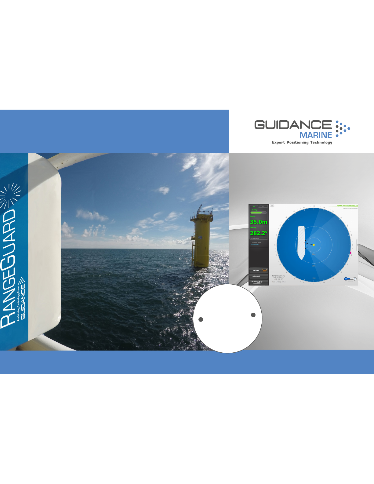
The RangeGuard Monopole system is the latest generation of Guidance Marine’s radarbased position reference products. Delivering accurate positional data to marine vessel
Dynamic Positioning (DP) control systems for automated approach and station keeping,
against simple monopole targets.
The RangeGuard Monopole System consists of three main parts:
•
RangeGuard Sensors
•
RangeGuard Monopole Processing Unit
•
RangeGuard Monopole Dashboard Software
RangeGuard Sensors
The RangeGuard Monopole system utilises two radar sensors which each have a fixed
beam with a 110° field of view in the horizontal plane. They are mounted on the edge of a
vessel so that the two sensor beams overlap which allows them to observe a monopole
target simultaneously. This information is then passed on to the processing unit so that it
can calculate the position of the monopole target.
System Overview
RangeGuard Monopole Processing Unit
The RangeGuard Monopole Processing Unit takes the observed signal from the two
sensors and uses this to calculate a precise range measurement from each sensor to the
monopole target. From these two measurements it then calculates the target position
relative to the vessel through trilateration and passes this value on to the client software
and the vessel’s DP system.
RangeGuard Monopole Dashboard Software
The RangeGuard Monopole Dashboard is the software application used to control
and monitor the RangeGuard Monopole system. It is installed on one or more marinespecification Type 3 Marine Processors or other computers running Windows® 7, usually
mounted on the bridge near to the controls of the vessel’s DP system.
The Dashboard gives the DP operator control of the RangeGuard Monopole system and
the data stream being fed to the DP system.
RangeGuard Monopole Dashboard Software
RangeGuard
Monopole
Processing Unit
RangeGuard Sensors
Page 8

l
8
Getting Started
This section covers the basics of using the RangeGuard Monopole system.
It contains the following pages:
•
Start Up and Shut Down (Page 9)
•
Screen Layout (Page 10)
•
Display Views (Page 18)
Page 9
l
9
RangeGuard Monopole Dashboard not
tracking
In Command
Dashboard
Monitoring
Dashboard
Dashboard Start Up and Shut Down
See Multi Dashboard
Systems (page 27)
for information on In
Command/Monitoring
functionality.
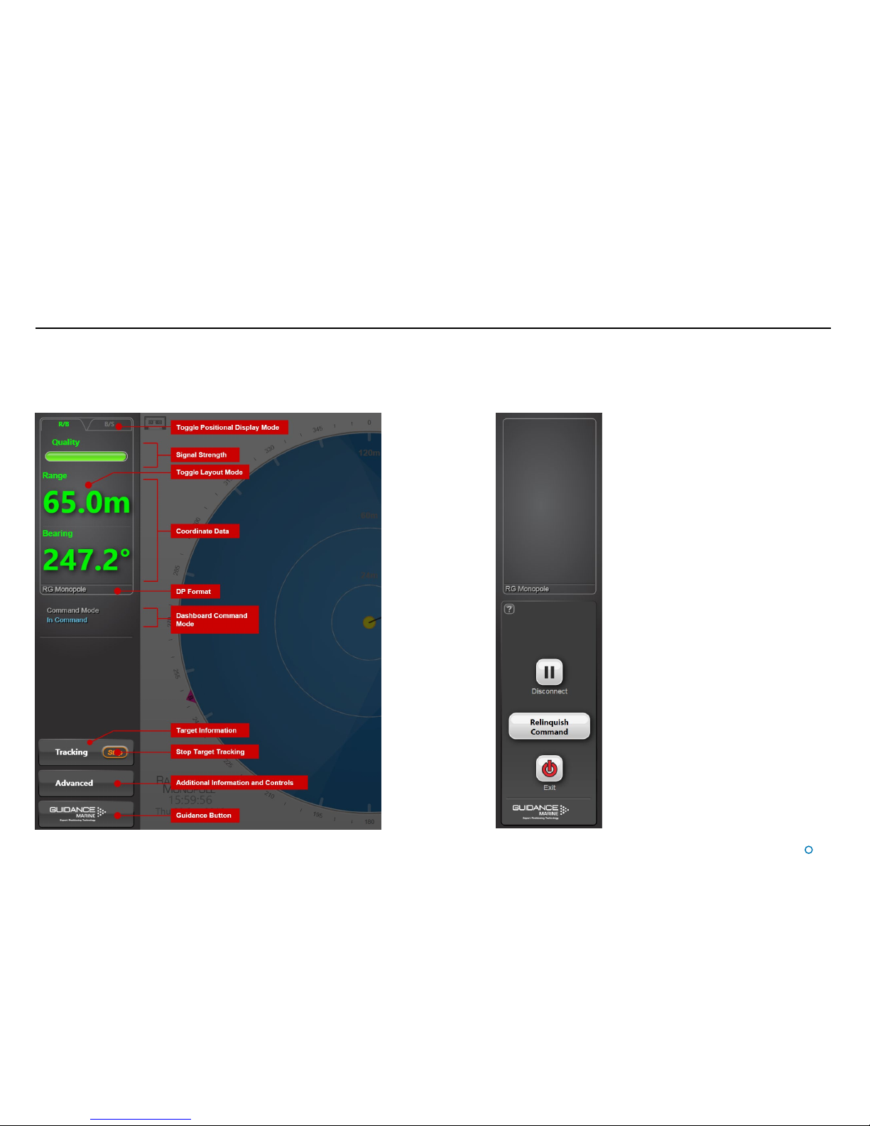
Shut Down
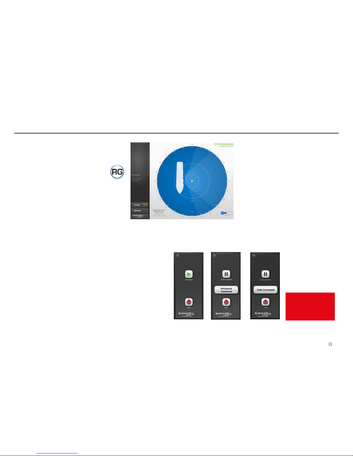
To Exit or Disconnect
Click on the Guidance button in the lower left corner of the screen. The set of buttons
revealed will depend on whether the Dashboard is In Command or in Monitoring mode.
Each button is explained below.
•
Disconnect—Ceases communications between the Dashboard computer and the
RangeGuard Monopole Processing Unit but leaves the Dashboard open.
•
Exit—Closes down the Dashboard without affecting the RangeGuard Monopole
Processing Unit.
Start Up
To Start the RangeGuard Monopole Dashboard
1. Ensure that the RangeGuard Monopole Processing Unit
is powered on.
2. Double-click on the Dashboard icon.
(Or run the Dashboard application from
Start > All Programs > Guidance Marine Ltd >
RangeGuard > RangeGuard Monopole Dashboard).
3. The Dashboard screen will appear. If a target is in view,
it will be displayed
To Connect
The Dashboard will automatically connect to the
RangeGuard Monopole Processing Unit at start up. If
the Dashboard has been manually disconnected or has
failed to connect then you can attempt to re-establish
communications using the Connect button.
Disconnected
Dashboard
Controls
Page 10

l
10
Screen Layout
The Dashboard screen is split into
three distinct sections, these are:
•
Main Screen and Bird’s Eye
View (BEV) (see page 11)
•
Side Bar (see page 13)
•
Menu Pane (see page 15)
Main Screen and Bird’s Eye View (BEV)
Menu PaneSide Bar
Dashboard Screen
Page 11
l
11
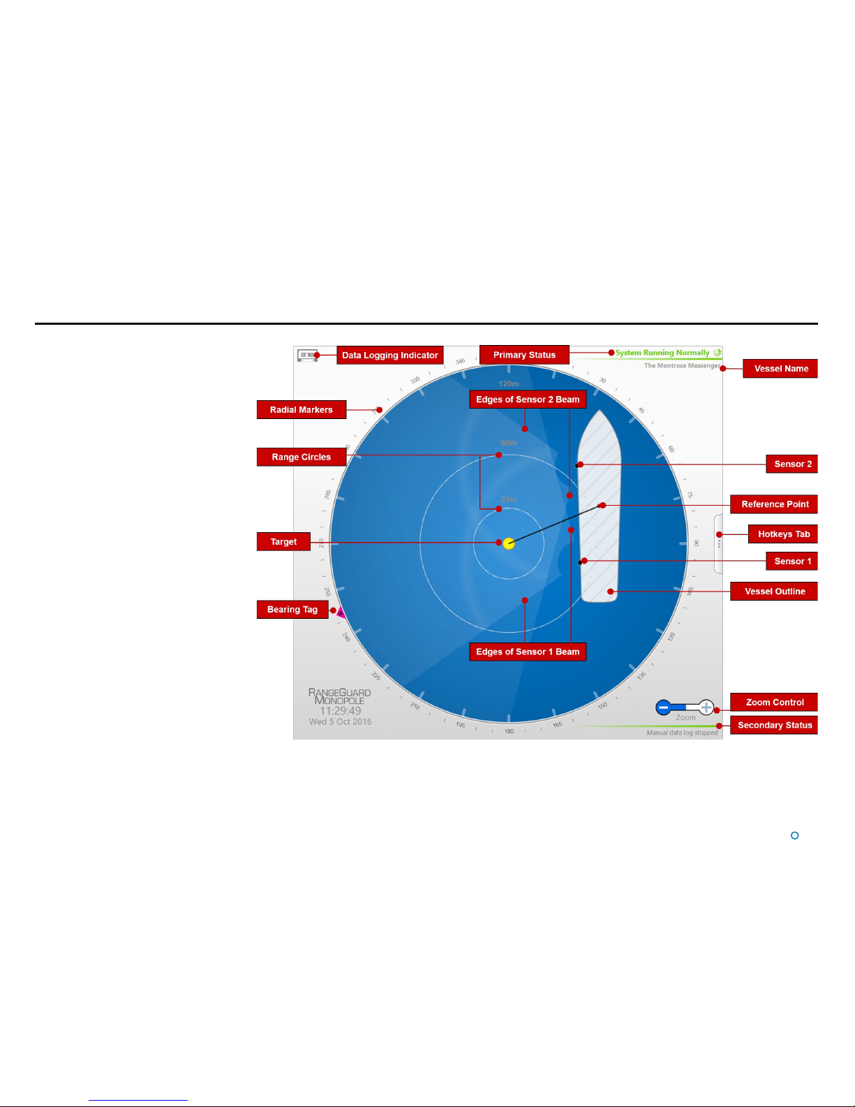
Main Screen and Bird's Eye
View (BEV)
The circular BEV depicts the operational area of
the RangeGuard Monopole system from above.
Vessel Outline
The length and breadth of the vessel can be
configured on the Vessel tab of the RangeGuard
Service Interface (see Installer’s Guide) so that the
vessel outline is correctly scaled and positioned
on the BEV.
Sensors
The black squares on or around the vessel
outline represent the RangeGuard Monopole
sensors. Their position and orientation relative
to the vessel are configurable using the
RangeGuard Service Interface (see Installer’s
Guide).
The field of view (FOV) of each sensor is indicated
by the shaded area radiating from each of the
sensors. When blanking is configured at short
range the shaded areas are offset to illustrate the
blind spots. Only areas where the two sensor
FOVs overlap are considered for target tracking.
Reference Point
The red dot on or near the vessel outline is
the reference point. This does not necessarily
correspond to a physical object, but is the point
in relation to which the range and bearing of the
target are expressed. The reference position
is configurable using the RangeGuard Service
Interface (see Installer’s Guide).
Target
The target is always at the centre of the BEV
and only available for RangeGuard Monopole
systems.
Screen Layout (Continued)
Page 12

l
12
Screen Layout (Continued)
Range Circles
The Range Circles act as a visual guide to show the distance between the vessel and the
detected target. Distances are shown in metres from the target. Use the Zoom Control to
change the scale of the display. (See page 12).
Radial Markers
These form an angular scale in degrees, clockwise around the circumference of the BEV.
Zero is defined by the direction of the bow of the vessel.
Bearing Tags
The bearing tag is displayed on the Radial Marker when the system is in tracking mode,
to indicate the bearing of the target. The visibility of this element depends on the which
coordinate system is being used to display the positional information (see Positional
Display Modes
on page 25).
Data Logging Indicator
This symbol is displayed when data is being logged to disk on the RangeGuard Monopole
Processing Unit. During a tracking operation the symbol is steady and when manual
logging is in progress it flashes.
Zoom Control
Click on the left-hand side of the control (marked ‘-’) to zoom out of the BEV display and
on the right-hand side (‘+’) to zoom in.
Status Display
This consists of two fields:
Primary
The primary part of the status display is in the upper-right corner of the Main Pane. It
indicates the current status of the system:
•
System Running Normally
•
System Disconnected
•
Waiting for connection
•
Communications Lost
•
Communications Error
Secondary
The secondary status display is located in the lower right corner of the Main Pane (beneath
the zoom function) and is normally hidden. It displays a flashing message for a number of
seconds in order to confirm an action taken by the user, e.g. starting manual data logging.
It can also display a persistent, static message if there is a communications problem.
Vessel Name
The name of the vessel configured on the Vessel tab of the RangeGuard Service Interface
(see Installer’s Guide).
Page 13
l
13
Screen Layout (Continued)
Side Bar
The Side Bar, the black pane to the left of the BEV, contains control and display
components in addition to the coordinates pane.
After pressing the
Guidance button:
Page 14

l
14
Hotkey Buttons
Selecting the Hotkeys tab on the right-hand side of the
Bird's Eye View (BEV) activates the 'Dashboard Hotkeys'
menu.
Screen Layout (Continued)
The following keys - and the corresponding buttons on the Dashboard Hotkeys
menu - act as shortcuts to application functions.
F1 Help menu
F2 Rotates the vessel clockwise
F3 Rotates the vessel counter-clockwise
F4 Toggles between BEV layout mode and Coordinates layout mode
F5 Toggles between enlarged and standard-sized reflections
F6 Toggles between the day view and night view
F7 Toggles between the About System pane and the full BEV display
F10 Capture a screenshot of the Dashboard interface and save it to disk
F11 Enables or disables the On-Screen Keyboard function
Alt+L Starts or stops manual data logging
Ctrl + Zoom-In
Ctrl - Zoom-Out
Esc When in operation confirmation mode, cancels the current operation request;
otherwise closes the Guidance Home menu or restores the main screen to full size
Return When in operation confirmation mode, confirm the current operation request
Page 15

l
15
Screen Layout (Continued)
Menu Pane
The Menu Pane, located across the bottom of the
Dashboard Screen, is not always visible. It appears
when the Tracking or Advanced buttons near
the foot of the Side Bar are pressed. This causes
the Main Screen to contract towards the top of the
screen. Clicking the same button for a second time
causes the Menu Pane to disappear and the Main
Screen to be restored to full size.
The Menu Pane is used to display a wide variety
of information and controls, accessed by further
buttons that become available once the Menu Pane
is in place.
Page 16

l
16
Screen Layout (Continued)
Coordinates View
Whilst tracking is in progress, the positional coordinates and the Bird’s Eye View can be
transposed, so that the coordinates are displayed in extra-large numerals on the main
screen, whilst a miniature BEV is shown at the top of the side bar. If tracking ends, the
layout automatically reverts to Bird’s Eye View, but as long as Coordinates View remains
selected, the main screen will again display coordinates once the next tracking operation
commences.
To Select Coordinates View
This can be done in a number of ways:
•
1. Navigate to Advanced > Display Options > Screen Layout.
2. Click on the Coordinates radio button.
•
Click on the Coordinate Data near the top-left corner of the screen.
•
Press F4.
•
Click on Switch To Coordinates Layout Mode in the Dashboard Hotkeys menu.
BEV Mode
Coordinates Mode
Page 17

l
17
Screen Layout (Continued)
Vessel Orientation
The Dashboard supports four different layouts of the Bird’s Eye View so that the operator
can choose the one which best represents his surroundings.
For instance, if the operator is facing forwards when using the Dashboard, he may want
the bow of the vessel in the BEV to point upwards, so that a target on the starboard side
of the vessel is shown on the right-hand side of the BEV.
There are two ways of setting the Vessel Orientation; one just for the current Dashboard
session and the other which will apply to all Dashboards in the system and will persist after
a Dashboard has been closed and re-opened.
To set Default Vessel Orientation:
This is done on the Vessel tab of the RangeGuard Service Interface (refer to the
RangeGuard Monopole Installer’s Guide).
To set Vessel Orientation for the Current Session:
1. Navigate to Advanced > Display Options > Screen Layout.
2. Click on the vessel outline that points in the required direction.
Alternatively, rotate the vessel clockwise by clicking F2 or the Rotate Vessel Clockwise
hotkey. Rotate anti-clockwise by clicking F3 or the Rotate Vessel Anti-Clockwise hotkey
Page 18

l
18
Display Views
To provide ample visibility during daytime operation and to limit glare during night shifts,
the Dashboard offers two display settings: Day Mode and Night Mode. In either mode the
brightness can be further adjusted by the Screen Brightness control.
To change the day/night mode and adjust brightness:
1. Navigate to Advanced > Display Options > Display Settings.
2. Click on one of the Day/Night Mode symbols.
3. Click on the left side of the Screen Brightness control to dim the screen and on the
right to make it brighter.
Night Mode
Day Mode
Alternatively, to toggle between day and night mode, use the keyboard shortcut F6 or
the Toggle Day/Night Mode button in the Dashboard Hotkeys panel
Page 19

l
19
This section explains how to set up the system prior to tracking a target and
describes information presented to the user whilst tracking is in progress.
It contains the following pages:
•
Working with Reections (Page 20)
•
Tracking Information Quality (page 21)
•
DP Feed (Page 22)
Tracking Basics
Page 20

l
20
Working with Reections
Detecting a Target
The RangeGuard Monopole System automatically detects a monopole target when it
comes into range and displays a yellow circle in the centre of the BEV.
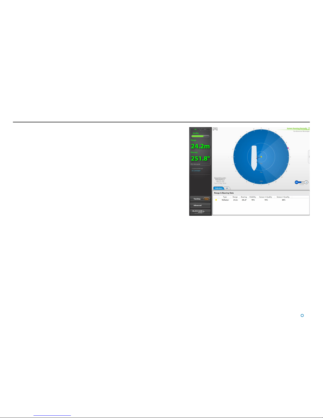
Reections Pane
The Reflections pane is obtained by clicking on the Tracking button and then on the
Reflections tab. It displays the following controls and information:
Range & Bearing Data:
Target - The target for the reflection matching that shown on the BEV. Clicking on the
target has the same effect as clicking on the target on the BEV
Type - The type of reflection as follows:
•
Reection: A target signal has been detected and veried
•
Reject: A target signal has been detected and rejected by the sensor
Range - The measured distance between the target and the vessel’s reference point,
expressed in metres.
Bearing - The bearing of the target in relation to the vessel’s centre-line, expressed in
degrees.
Visibility - The strength of the detected signal from the target, expressed as a percentage.
Sensor Quality - The confidence of the target range from the respective sensor,
expressed as a percentage.
Page 21

l
21
Tracking Information Quality
The RangeGuard Monopole System relies on each sensor emiting a radar beam and from the reflected return calculating the range to the monopole target. The system then uses these
measurements to calculate the target position.
Before tracking has been selected, the Data Quality and Coordinates area in the upper left corner of the screen is grey. After tracking has started, the coordinates are displayed in green
and the quality bar is largely filled.
If the position reported to the DP system is no longer valid, e.g. because another vessel has obscured the monopole target, this is indicated by a change of colour and a reduction in the
filled portion of the quality bar.
Green: Position is good
Amber: Position is ok
Red: Position is invalid
Page 22

l
22
DP Feed
The DP Feed is the data that the RangeGuard Monopole System sends to the vessel’s
Dynamic Positioning system. Several different data message formats are supported; it is
important that the RangeGuard Monopole System and DP systems both use matching
formats.
Configuration of the DP output channel is done using the RangeGuard Service Interface
(refer to 92-0523-4-A RangeGuard Monopole Installer’s Guide). The Dashboard contains a
read-only menu pane that displays the state of the DP output channels, which DP format is
configured and data emitted relating to eaither the target or features that each sensor can
see.
Viewing DP Feed information
1. Click on Advanced button.
2. Click on the DP Feed button.
See document 92-0523-4-A RangeGuard Monopole Installer’s Guide for a description
of the available DP message formats and the different modes of behaviour.
Page 23

l
23
This section describes the target tracking and how to set it up. It is for general guidance
only and does not provide an exhaustive explanation of target tracking using the
RangeGuard Monopole system, nor does it form the basis of a contract. Implementation
of the material covered in this section will vary according to the type of DP system used in
conjunction with the RangeGuard Monopole system. The use of, or reliance on, anything in
this section is therefore entirely at the user’s own risk and should only be undertaken after
assessment of its accuracy, completeness and suitability for the proposed use.
This section contains the following pages:
•
Introduction to Target Tracking (Page 24)
•
Positional Display Modes (Page 25)
Target Tracking
Page 24

To Start Tracking
When the system has detected a monopole target, a Start button is embedded in the
Tracking button on the Side Bar.
1. Click on the Start button. The target refelection will change to the selected state (with
a red dash around the outside and number “1” superimposed). Alternatively, click on the
target reflection on the Bird’s Eye View or the Reflections menu pane.
2. Click on the Apply button to confirm and begin tracking.
To Stop Tracking
Whilst tracking is in progress, a Stop button is embedded in the Tracking button on the
Side Bar.
1. Click on the Stop button.
2. Click on the Apply button to confirm.
l
24
Introduction to Target Tracking
The RangeGuard Monopole system can only track a single monopole target.
Page 25

The relative positions of the vessel and target can be expressed either as range and
bearing values, or as bow and starboard positions. The position of the target is reported
relative to the RangeGuard Monopole system reference point (or tracking reference point).
See the 94-0523-4-A RangeGuard Monopole Installer’s Guide, for more information about
this.
When tracking, select the required mode by clicking the appropriate tab above the Data
Quality area:
Range & Bearing
Range and Bearing mode displays the distance and the bearing of the target from the
tracking reference point. The radial markers around the outside of the BEV are zeroed in
line with the vessel bow and a magenta tag marks the bearing which is the angle of the
target clockwise from the bow.
Bow and Starboard Axes
In this mode, the position of the target is expressed in metres from the tracking
reference point along the Bow and Starboard axes. The Bow and Starboard
coordinate axes are always parallel with the vessel’s own axes.
l
25
Positional Display Modes
Page 26

Multi - Dashboard Systems
This section contains the following pages:
•
Dashboard In Command Mode (See page 27)
•
Dashboard Monitoring Mode (See page 28)
l
26
Page 27

Dashboard In Command Mode
In a RangeGuard Monopole system multiple Dashboards can be connected to the
server simultaneously. Only one of these can be In Command at any given time; the
others must be in Monitoring mode.
When running In Command mode, all control functions are available. Any changes
made to the tracking or server-related settings at the In Command Dashboard will be
visible on the screens of the Monitoring Dashboards. On the other hand, display options
such as Screen Brightness or Zoom level can be set differently on each individual
Dashboard, whether it is Monitoring or In Command.
If there are no Dashboards in command of a RangeGuard Monopole system, the
next Dashboard to connect will automatically become In Command of the system.
Subsequent Dashboards connected will default to Monitoring mode.
Whenever the system is running, a Monitoring Dashboard can be promoted to In
Command as shown on the right.
When another Dashboard
takes command the
Dashboard that was
previously In Command is
automatically switched to
Monitoring mode.
To switch a Dashboard from Monitoring mode to In Command mode:
1. Click on the Guidance button.
2. Click on the Take Command button.
Example of controls available only In Command mode
l
27
Page 28

Dashboard Monitoring Mode
When the Dashboard is running in Monitoring mode, the controls relating to the Dashboard
itself are active, but those relating to the server are disabled. A Monitoring Dashboard
displays the same reflections and positional data as the In Command Dashboard, but it
cannot initiate or stop target tracking and manual data logging.
Example of inactive controls in Monitoring mode
To switch a Dashboard from In Command mode to Monitoring mode:
1. Click on the Guidance button.
2. Click on the Relinquish Command button.
l
28
Page 29

l
29
This section contains the following pages:
•
Serial Numbers and Software Versions (Page 30)
•
Data Logging (Page 32)
•
Using the On-Screen Keyboard (Page 34)
•
Working with Alarms (Page 35)
•
International Standards Compliance (Page 37)
•
System Specications (Page 38)
•
Index (Page 39)
Support Information
Page 30

l
30
Serial Numbers and Software Versions
Software Version Information
The About System pane provides version information about the Dashboard and the
software within the RangeGuard Monopole server. It also contains the serial number of the
RangeGuard Monopole System.
Serial Numbers and Software Version Numbers are used to identify the hardware
configuration and product revision of each RangeGuard Monopole System. They will be
requested by Guidance Marine in the event of an application service or support call to the
company.
To Display the About System Pane
1. Click on the Advanced button.
2. Click on the About System button.
Alternatively, click F7 or the About System button via the Hotkey tab.
Page 31

l
31
Product Label
Connection Panel
RangeGuard Sensor
Part Number
RangeGuard Sensor
Serial Number
Serial Numbers and Software Versions (continued)
Product Labels
Part Numbers and Serial Numbers can be found on the product labels fixed to the rear of the
processing unit and sensors.
Processing Unit
Part Number
Processing Unit
Serial Number
Product Label
Page 32

l
32
Data Logging
During target tracking, the system automatically generates a set of operation logs that can
be analysed by a service engineer to diagnose any system faults. Logging can also be
started manually, when the system is not tracking (see below).
When logging is in progress, the following symbol is displayed in the top lefthand corner of the main pane. In the case of manual logging, the symbol flashes.
Logs can be exported and e-mailed to Guidance Marine
(customerservices.uk@guidance.eu.com) or your DP supplier in the event of a problem.
Logging Extended Data
When the Log Extended Data box is ticked, extra information will be included in all data
logs that are recorded. This may be useful as a short-term measure for diagnosing a
particular problem, but in general the box should be left un-ticked in order to conserve disk
space.
To Enable Extended Data Logging
1. Navigate to Advanced > Data Logger.
2. Tick the Log Extended Data box.
This can be done even if tracking or manual logging are already in progress.
Starting and Stopping Manual Logging
To start manual logging:
Firstly ensure that the Dashboard is in command (see
Dashboard – In Command mode on page 27) then either:
1. Navigate to Advanced > Data Logger.
2. Click on the Start button.
Or
Press Al t+L.
Or
1. Click on the Hotkeys tab.
2. Click on the Start Manual Data Log button.
To stop manual logging:
Either
1. Navigate to Advanced > Data Logger.
2. Click on the Stop button.
Or
Press Al t+L.
Or
1. Click on the Hotkeys tab.
2. Click on the Stop Manual Data Log butto n.
Or
Click on the flashing Data Logging Indicator in the top
left of the main screen.
Page 33

l
33
Data Logging (continued)
Taking Screenshots
The Grab Screenshot option records every detail of the current screen and stores it at the
same location as the data logs. Up to ten screenshots are held and if a further screenshot
is taken, the oldest is automatically deleted.
To take a screen shot:
Either
1. Click on the Hotkeys tab.
2. Click on Grab Screenshot.
Or
Press the F10 key.
The Grab Screenshot and Start Manual
Data Log but tons
Exporting Data Logs
The most recent data logs can be exported to a remote drive on the Dashboard
computer.
To Export Data Logs:
1. Insert a USB or other removable drive into the Dashboard computer.
2. Select the period for which you wish to export logs
(Last Hour, Last 4 Hours, etc).
3. Select Destination Drive from drop-down list, if not already displayed.
4. Click on Export Data Logs.
Use the Refresh button to update the list of USB drives and the Available Space
value.
N.B. In addition to data logs, screenshots from the selected time period and a list of
alarms are also exported.
Page 34

l
34
Using the On-Screen Keyboard
In order to accommodate systems without keyboards, the Dashboard provides an OnScreen Keyboard (OSK) option. This enables text to be input using only a mouse, trackball
pointer or touch screen.
To enable the on-screen keyboard
If, during installation, you selected to enable the Dashboard’s on screen keyboard, then it
will already be enabled.
Otherwise, click F11 or the Enable On Screen Keyboard button in the Dashboard
Hotkeys menu.
To use the on-screen keyboard
Simply click on any text entry field and the OSK will pop-up ready for use:
When you have finished using the OSK, proceed to the next relevant action (e.g. clicking
on the Apply button), or else click on a different part of the screen, and the OSK will
disappear.
Click on the necessary keys on the on-screen keyboard using your mouse/trackball or by
tapping the touch screen.
Page 35

When a Fatal alarm occurs, communications with the sensor are disabled.
In order to return to normal operation, ensure that the fault condition has been
cleared and click on the Connect button in the side bar. If communications are not
re-established, power the server off, wait for 20 seconds then power back on.
l
35
Working with Alarms
During operation, the RangeGuard Monopole system produces an audit trail of event
messages, which are classified into four severity levels. These are, in increasing order of
severity: Information, Warning, Error and Fatal. As these alarms are raised, the Dashboard
lists them within the Alarms pane.
Click on any alarm to display details about it in the right-hand section of the Alarms pane:
Filtering Alarms
A filter is available to suppress the display of particular alarm types. By default, the filter is
activated and causes information messages to be hidden.
Click on the Alarm Filter button to toggle between activated
and de-activated .
Click on the Filter Selection button to choose which types of alarm are to be filtered out:
A tick means that alarms of the corresponding severity are always viewable in the alarms
list. No tick means that alarms of that severity are hidden when the filter is activated.
The severity and current state of an alarm are reflected in its colour and shape:
•
Information—grey symbols
•
Warning—orange symbols
•
Error—red symbols
•
Fatal—red symbols
The arrowhead symbol indicates that an alarm condition is persisting; an alarm in this state
will show a Start time but not a Stop time.
The square symbol means that the alarm condition no longer exists, therefore the alarm will
show both Start and Stop times.
The pause symbol indicates an instantaneous alarm. In this case, the Start and Stop times
are identical.
When an Error or Fatal alarm is raised, the Advanced button on the side bar is shaded
red as in the illustration above. If no menu is open already, the Alarms pane is opened
automatically. Once the Advanced button has been clicked, it returns to its normal
appearance.
Page 36

l
36
Using the Current and Historic Alarms Tabs
There are two tabs on the Alarms pane, each containing a list of alarms:
•
The Current Alarms tab displays new alarms (raised since the Dashboard was last
opened).
•
The Historic Alarms tab displays alarms that have been cleared from the Current
Alarms tab.
Current alarms are automatically transferred when the Dashboard is closed or when the
maximum number of Current Alarms has been reached.
Items on the Current Alarms tab cannot be deleted, they may only be moved to the
Historic Alarms tab. Only items on the Historic Alarms tab can be permanently deleted.
To accept alarms on the Current Alarms Tab
1. Click on Advanced > Alarms and ensure that the Current Alarms tab is in focus.
2. Select the alarms that you wish to move into the Historic list:
To accept one alarm—Click on the alarm and click on the
button.
To accept all alarms—Click on the
button
.
3. If accepting all alarms, click Apply to move these alarms onto the Historic Alarms tab.
To delete alarms on the Historic Alarms tab
1. Click on Advanced > Alarms and ensure that the Historic Alarms tab is in focus.
2. Select the alarms to delete:
To delete one alarm – click on the alarm entry and then on the
button.
To delete all alarms – click on the
button.
3. If deleting all alarms, click Apply to confirm.
Working with Alarms (Continued)
!
This will not apply to alarms that have been hidden by the filter mechanism.
!
This will not apply to alarms that have been hidden by the filter mechanism.
Page 37

l
37
International Standards Compliance
RangeGuard
European Union
The equipment is permitted to be used in all EU member states
without the need for a specific administrative licence.
The RangeGuard K-Band Sensor meets the R&TTE Directive.
The equipment complies with EN 60945:2002.
USA
Use of the RangeGuard system in the United States of America is authorised
by the Federal Communications Commission. FCC ID: VYMRangeGuard.
Page 38

l
38
System Specications
System Performance
Operating Range 3 to 100 metres (depending on sensor configuration)
Range Repeatability
0.15m (1σ) at 100m
Angular Repeatability
0.15° (1σ) at 100m (depending on sensor configuration)
Sensor
Transceiver Type Frequency Modulated Continuous Wave (FMCW)
Frequency Band 24.05GHz – 24.25GHz (Licence Exempt Short Range Device)
Maximum Power Output <100mW EIRP (EN 300 440 Compliant)
Azimuth Beam Width 110° (10dB Width)
Vertical Beam Height +/- 5.5°
Vessel Interface
Power Requirement 85 to 264V AC 45-65 Hz 5A, nominal 100W
I/O Sensor to Dashboard - Ethernet 100Base-T
Sensor to DP - RS422, 9600 to 115200 baud
Data Formats RangeGuard Monopole Tracking DP feed format
Control & data Display
Operating System Windows 7 Embedded
Software Dedicated real-time interactive
Hardware Options Type 3 Marine Processor + 15” TFT monitor
Hatteland Type Approved integrated PC/TFT screen
Environmental
Ambient Temperature Range -25 to +55°C
Atmospheric Conditions Operates in fog, heavy rain, snow and ice conditions
Water Protection (Sensor) IPX6 certified
Standards Compliance EN 60945
RF Immunity Resistant to S and X band radar
Sensor Mechanical
Height 23 cm
Width 17 cm
Depth 13 cm
Weight 4 kg
Max Cable run per sensor Up to 100m (CAT5e SCTP cable, Min AWG 24)
Page 39

l
39
I
In Command 27
International Standards Compliance 37
I/O 38
L
Labels 31
Layout Mode 14, 16
Logging 32
Logging Indicator 12, 32
M
Main Screen 11
Maximum Power Output 38
Manual Data Logging 12, 14, 28, 32
Mechanical Specications 38
Menu Pane 15
Monitoring 28
Monopole Target 7, 20, 21, 24
N
Night Mode 18
O
On-Screen Keyboard 34
Operating Range 38
Operating System 38
P
Part Numbers 31
Positional Display Modes
Range/Bearing 25
A
About System Pane 14, 30
Advanced Button 15
Alarms
Accepting 36
Deleting 36
Filtering 35
Historic 36
Alarms Pane 35
Alt+L 14, 32
Angular Repeatability 38
Atmospheric Conditions 38
Azimuth Beam Width 38
B
Bearing Tags 12
Bird’s Eye View (BEV) 10, 11
Bow Axis
C
Command Mode
In Command 27
Monitoring 28
Coordinate Data 16
Coordinates View 16
D
Dashboard Overview 10
Dashboard Software 2, 7
Dashboard Start Up/Shut Down 9
Data Formats 38
Data Logger Pane 32
Data Logging
Exporting Data Logs 33
Logging Extended Data 32
Logging Indicator 32
Manual Data Logging 32
Day Mode 18
Delete Alarms 36
Dimensions 38
Disconnect 9
Display settings Pane 18
Dust Protection 38
Document History 3
DP Feed
DP Feed Pane 22
Message Format 22
E
European Union 37
Exit 9
Exporting Data Logs 33
Extended Data Logging 33
F
FCC 2, 37
Field of View 7, 11
Frequency Band 38
G
Guidance Button 9, 13, 27, 28
H
Hardware Options 38
Historic Alarms 36
Hotkey Buttons 14
Index
Page 40

l
40
Vessel
Interface 38
Name 12
Outline 11, 17
W
Water Protection 38
Z
Zoom Control 12
Bow/Starboard 25
Power Requirement 38
Primary Status Display 12
Processing Unit
Overview 7
Product Labels 31
R
Radial Markers 12
Range and Bearing 25
Range Circles 12
Range Repeatability 38
RangeGuard Service Interface 11, 12, 17, 22
Reconnect
Reference Point 11
Reections 20
Relinquish Command 28
RF Immunity 38
S
Screen Brightness 18, 27
Screen Layout 10
Screenshot 33
Secondary Status Display 12
Sensor
Overview 7
Serial Numbers 30
Side Bar 13
Software 30
Software Versions 30
Standards 37, 38
Starboard Axis 25
Start
Manual Data Logging 12, 14, 28, 32
Tracking 24
Status Display
Primary 12
Secondary 12
Stop
Manual Data Logging 12, 14, 28, 32
Tracking 24
System Overview 7
System Operating Region
Field of View 7, 11
T
Take Command 27
Target
Reections 20
Selection 24
Tracking 24
Temperature Range 38
Tracking
Button 24
Information Quality 21
Reference Point 11
Transceiver Type 38
Type 3 Marine Processor 7, 38
U
USA 2, 37
V
Vertical Beam Height 38
Index (Continued)
Page 41

 Loading...