

Page 1
Guidance Marine Ltd, 5 Tiber Way, Meridian Business Park, Leicester LE19 1QP, UK www.guidance.eu.com
T: +44 116 229 2600 E: sales@guidance.eu.com www.marine.direct
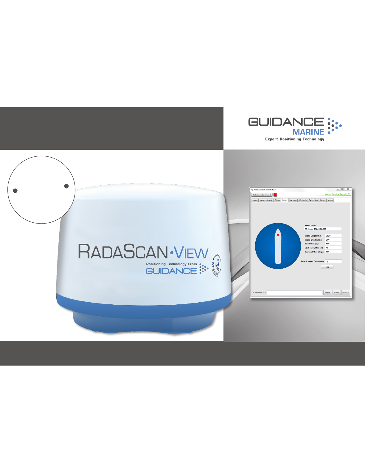
RadaScan® View Installer’s Guide
W
A
R
R
A
N
T
Y
S
e
e
o
u
r
s
t
a
n
d
a
r
d
t
e
r
m
s
o
f
s
a
l
e
Q
U
A
L
I
T
Y
A
S
S
U
R
E
D
3
YEAR
Page 2
Guidance Marine Ltd,
5 Tiber Way
Meridian Business Park
Leicester
LE19 1QP
UK
Tel: +44 116 229 2600
UK Support:
+44 116 229 2665
(365 days a year, 08:00 - 20:00 hours UTC)
customerservices.uk@guidance.eu.com
USA Support: +1 504 305-1120
customerservices.us@guidance.eu.com
Asia Support: +65 6734 6365
customerservices.sg@guidance.eu.com
Web: www.guidance.eu.com/customer-support
RadaScan View Installer’s Guide
Issue Date: 02/03/2016
Document No: 94-0492-4-A
Copyright © 2016 Guidance Marine Limited. All Rights Reserved.
Copyright in the whole and every part of this document belongs to Guidance Marine Limited
(the “Owner”) and may not be used, sold, transferred, copied or reproduced in whole or in part
in any manner or form or in or on any media to any person other than in accordance with the
terms of the Owner’s Agreement or otherwise without the prior written consent of the Owner.
“RadaScan View” is a trademark and “RadaScan” is a registered trademark of Guidance Marine
Ltd. ”Windows” is a trademark of Microsoft Corporation. All other brand or product names are
trademarks or registered trademarks of their respective companies or organisations.
Serial No:
Date of Shipment from UK:
Sensor Software Version: RSI Software Version:
VYMRADASCAN
Page 3

Document Number Changes Issue Date
94-0492-4-A First release of RadaScan View Installer's Guide 02/03/2016
Document History
3
Page 4

Introduction
Welcome ................................................................................................................... 6
System Overview ....................................................................................................... 7
Important Safety Notes .............................................................................................. 8
Non-ionising Radiation .......................................................................................................8
Risk of Electric Shock ........................................................................................................8
Isolating the Sensor ...........................................................................................................8
Lifting the Sensor ...............................................................................................................8
Serial Numbers and Software Versions ......................................................................9
Product Labels ..................................................................................................................9
Software Version Information .............................................................................................9
To Display the About System Pane ....................................................................................9
Installing the Sensor Hardware and Software
Mounting the Sensor ............................................................................................... 11
Avoiding Other Sources of Radiation ................................................................................12
Operating Area Astern (e.g. PSV) .....................................................................................13
Operating Area Forward (e.g. Shuttle Tanker) ...................................................................14
Operating Area to Port or Starboard (e.g. Track and Follow) .............................................15
Sensor Dimensions .................................................................................................. 16
Mounting Template .................................................................................................. 17
Universal Mounting Bracket ..................................................................................... 18
Sensor Connections—Direct ................................................................................... 19
Sensor Connections—Separate Connection Box ..................................................... 20
Cable Routing Diagram - Direct Connection ............................................................ 21
Cable Routing Diagram - Separate Connection Box ................................................ 22
Cable Routing Diagrams - Processor and Monitor Options ...................................... 23
Sensor Information Display ...................................................................................... 24
Installing the Sensor Software .................................................................................. 26
Installing the Marine Processor
Installing RadaScan View Client Software onto a Type 3 Marine Processor .............. 28
Installing RadaScan View Client Software onto other Types of Computer ................. 29
Conguring the RadaScan View System
Using the RadaScan Service Interface ..................................................................... 31
Network Communication Settings ........................................................................... 32
Vessel Definition .......................................................................................................34
Blanking Zone ......................................................................................................... 38
DP Feed Configuration ............................................................................................ 39
Information Tabs ...................................................................................................... 41
Installing Responders
Responder Overview ............................................................................................... 44
Positioning Responders ........................................................................................... 46
Mounting Responders ............................................................................................. 47
Charging Responders .............................................................................................. 49
Operating Responders ............................................................................................ 50
Appendices
International Standards Compliance ........................................................................ 52
RadaScan View Transceiver .............................................................................................52
RadaScan Responders ....................................................................................................52
Part Numbers .......................................................................................................... 53
DP Message Types .................................................................................................. 54
UPS and Cable Specifications ................................................................................. 58
Installation Checklist ................................................................................................ 59
Index ....................................................................................................................... 61
Table of Contents
4
Page 5
This section provides an introduction and overview of the RadaScan View system.
It contains the following pages:
•
Welcome (page 6)
•
System Overview (page 7)
•
Important Safety Notes (page 8)
•
Serial Numbers and Software Versions (page 9)
FCC ID: VYMRADASCAN
THIS DEVICE COMPLIES WITH PART 15 OF THE FCC RULES. OPERATION IS SUBJECT
TO THE FOLLOWING TWO CONDITIONS: (1) THIS DEVICE MAY NOT CAUSE HARMFUL
INTERFERENCE, AND (2) THIS DEVICE MUST ACCEPT ANY INTERFERENCE RECEIVED,
INCLUDING INTERFERENCE THAT MAY CAUSE UNDESIRED OPERATION.
NOTE: THE GRANTEE IS NOT RESPONSIBLE FOR ANY CHANGES OR MODIFICATIONS
NOT EXPRESSLY APPROVED BY THE PARTY RESPONSIBLE FOR COMPLIANCE. SUCH
MODIFICATIONS COULD VOID THE USER’S AUTHORITY TO OPERATE THE EQUIPMENT.
Introduction
5
Page 6

Welcome to the RadaScan View Installer’s Guide. It explains how to mount and install
the RadaScan View system onto a vessel. For instructions on how to use the system,
please see the RadaScan View Operator’s Guide (Doc No. 94-0491-4).
Please read the Important Safety Notes on page 8 before beginning the installation.
The Installing the Sensor Hardware and Software section on page 10 describes
where to mount the RadaScan View sensor on the vessel, and how to connect it to the
RadaScan View marine processor and the vessel’s DP system. It also explains how to
upgrade the sensor software, if required.
The Installing the Marine Processor section on page 27 gives relevant information
for mounting and setting up the marine processor and explains how to upgrade the
RadaScan Dashboard software, if required.
The Configuring the RadaScan View System section on page 30 explains how to
configure the system for your vessel.
The Installing Responders section on page 43 explains how to mount and use
RadaScan Responders.
!
NOTE: Installation of a RadaScan View system should be carried out by a
suitably qualified and competent engineer.
Welcome
6
Page 7
The RadaScan View system is the latest generation of Guidance Marine’s radar-based position
reference products, suitable for use within the 500m safety zone. Delivering accurate positional
data to marine vessel DP (dynamic positioning) control systems for automated approach
and station keeping, it has the additional capability to display a radar image representing the
surroundings of the vessel.
With similar all-weather capabilities and precision as the larger-scale RadaScan system, the
reduced size and weight of the RadaScan View sensor allows it to be used on smaller vessels
than those traditionally associated with RadaScan systems. Both RadaScan and RadaScan View
sensors are compatible with RadaScan responders.
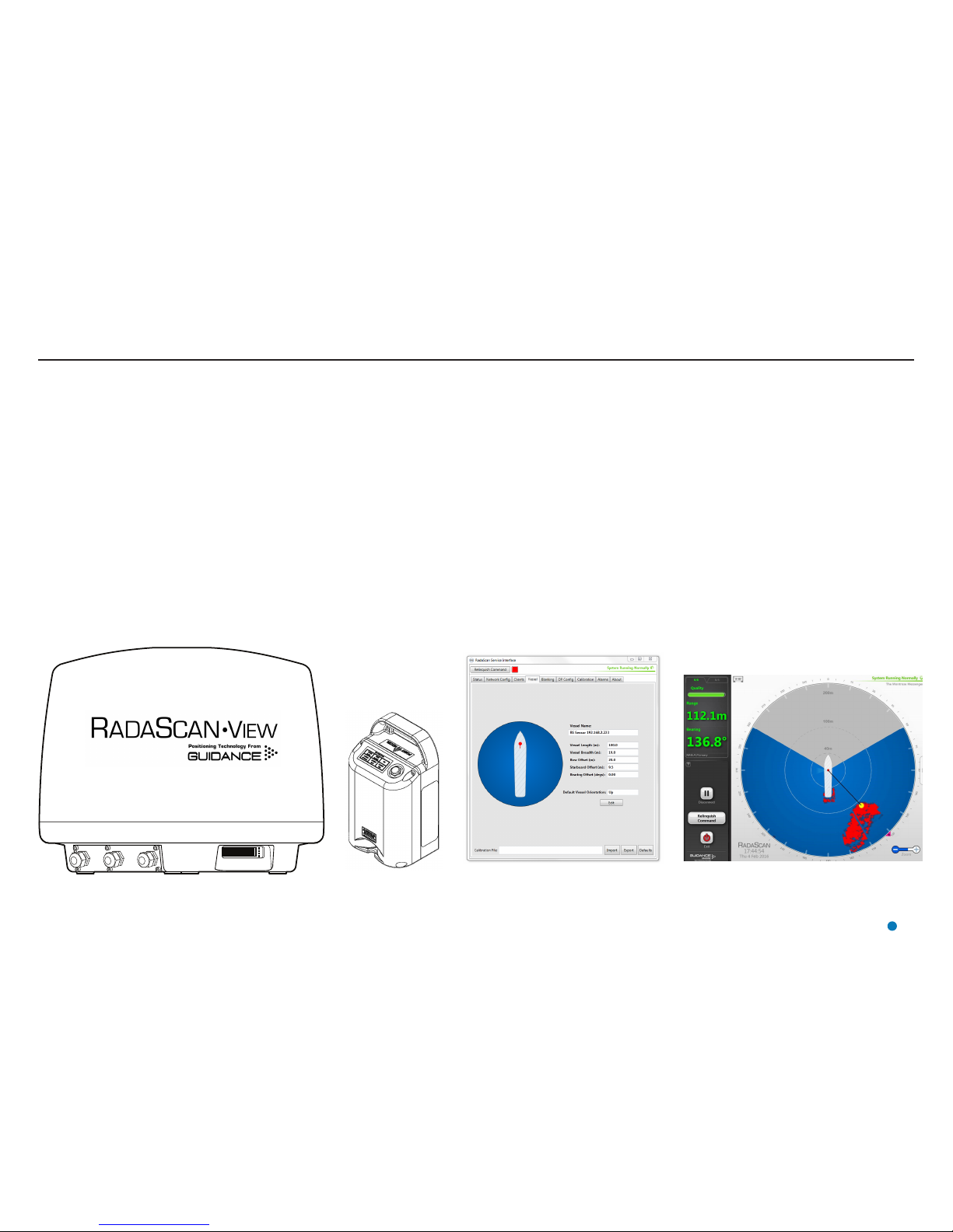
The RadaScan View System consists of three main parts: The Sensor, the Client Software and the
Responder:
RadaScan View Sensor
The RadaScan View Sensor is a rotating radar scanner mounted on the DP-equipped vessel. It
emits a microwave beam and detects the reflections returned by any RadaScan Responders that
are within range. It is connected to the vessel’s DP system and to the Dashboard, and can output
the radar image in ASTERIX Category 240 open data format for use by a third party application
(contact Guidance Marine for instructions on how to enable the ASTERIX output channel).
System Overview
RadaScan View Client Software
The RadaScan Service Interface (RSI) and RadaScan View Dashboard are software applications
used to configure, control and monitor the RadaScan View system. They are installed on one
or more marine-specification Type 3 Marine Processors or other computers running Microsoft
WindowsTM, usually mounted on the bridge near to the controls of the vessel’s DP system.
The RSI is used for system configuration and replaces the Service Access mode of the Dashboard
or Console in earlier versions of the RadaScan system.
The Dashboard gives the DP operator control of the RadaScan View system and the data stream
being fed to the DP system.
RadaScan Responder (Target)
One or more responders are mounted on the target platform or vessel. Each responder returns a
modulated radar reflection that carries its unique ID number back to the RadaScan View Sensor.
The precise range and bearing of each responder is measured by the sensor. This is used to
calculate the exact position of the RadaScan View Vessel relative to the target structure or vessel.
The positional data is fed directly into the vessel’s DP system.
RadaScan View Sensor RadaScan
Responder
RadaScan Service Interface RadaScan View Dashboard
7
Page 8
Non-ionising Radiation
The RadaScan View sensor emits non-ionising radiation with
an output power of 1 Watt when transmitting.
This equipment should be treated with the same safety
precautions as other marine radar devices.
ALWAYS keep a minimum safe distance of 1 metre
from the dome when the unit is operational.
Risk of Electric Shock
Disconnect the mains electricity supply before opening the
connection panel or removing the radome cover.
CAUTION—DOUBLE POLE/NEUTRAL FUSING.
Isolating the Sensor
For PERMANENTLY CONNECTED EQUIPMENT, a readily
accessible disconnect device shall be incorporated external to
the equipment.
For PLUGGABLE EQUIPMENT, the socket-outlet shall be
installed near the equipment and shall be easily accessible.
Lifting the Sensor
On install, the sensor should be moved to the top of the ship
in its STTC (Special to Type Transit Case). The transit case
must be carried using a correctly specified and weight-rated
cargo-net.
!
The transport case handles are not rated or weight
tested, and should not be used as lifting points for this
task.
Important Safety Notes
!
8
Page 9
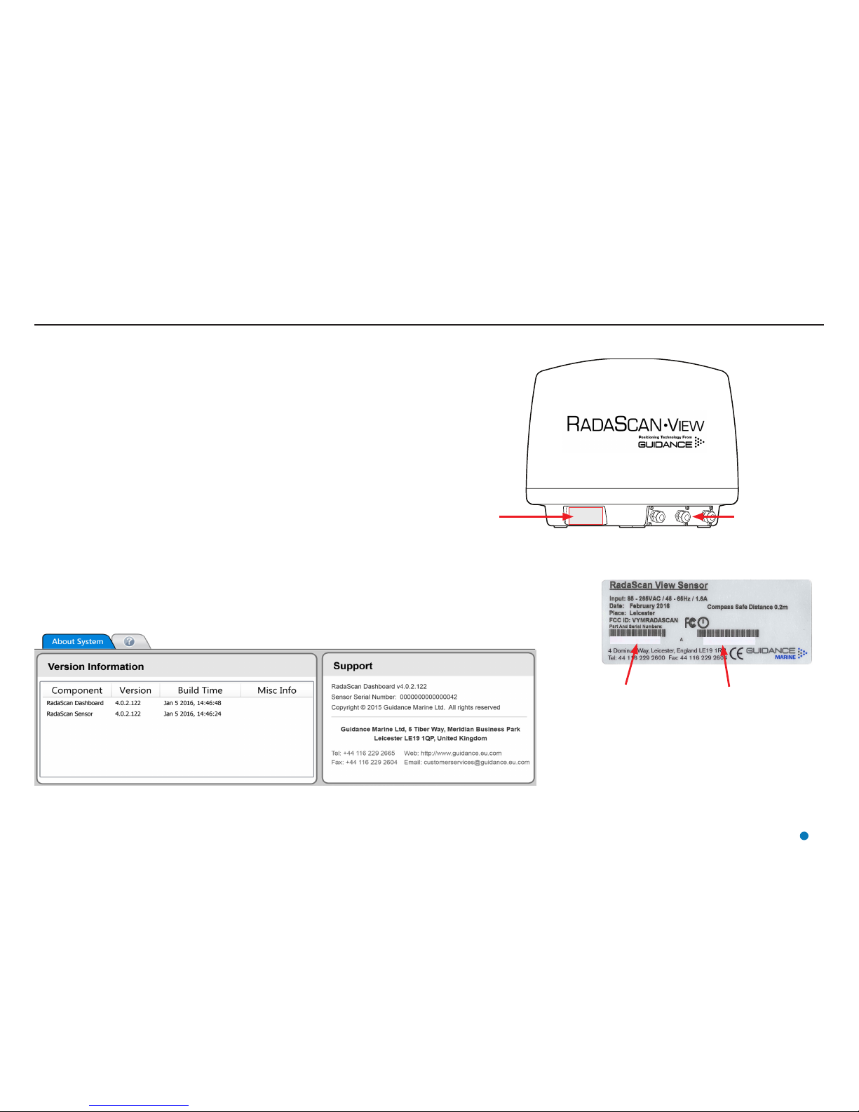
Serial Numbers and Software Versions
Product Label
Connection Panel
Software Version Information
The About System pane provides version information about the Dashboard and the software within
the RadaScan View sensor. It also contains the serial number of the sensor.
Serial Numbers and Software Version Numbers are used to identify the hardware configuration and
product revision of each RadaScan View sensor. They will be requested by Guidance Marine in the
event of an application service or support call to the company.
Product Labels
Part Numbers and Serial Numbers can be found on the product label fixed on the side of the
sensor, above the connection panel.
RadaScan View Sensor
Part Number
RadaScan View Sensor
Serial Number
To Display the About System Pane
1. Click on the Advanced button.
2. Click on the About System button.
Alternatively, click F7 or the About System button via the Hotkey tab.
XX-XXXX-X-X
XXXXXXXXX
9
Page 10
This section explains where and how to mount the RadaScan View Sensor on the vessel.
It contains the following pages:
•
Mounting the Sensor (page 11)
Avoiding Other Sources of Radiation (page 12)
Operating Area Astern (e.g. PSV) (page 13)
Operating Area Forward (e.g. Shuttle Tanker) (page 14)
Operating Area to Port or Starboard (e.g. Track and Follow) (page 15)
•
Sensor Dimensions (page 16)
•
Mounting Template (page 17)
•
Universal Mounting Bracket (page 18)
•
Sensor Connections—Direct (page 19)
•
Sensor Connections—Separate Connection Box (page 20)
•
Cable Routing Diagram - Direct Connection (page 21)
•
Cable Routing Diagram - Separate Connection Box (page 22)
•
Cable Routing Diagrams - Processor and Monitor Options (page 23)
•
Sensor Information Display (page 24)
•
Installing the Sensor Software (page 26)
10
Installing the Sensor Hardware and Software
Page 11
Mounting the Sensor
Applications and Vessel Types
The sensor’s mounting position depends on the application for which it is used. If your particular
application does not match the ones covered in this manual, please contact Guidance Marine and
your DP supplier to ensure that the RadaScan View and DP systems are configured correctly.
•
Operating Area Astern (e.g. PSV) (page 13)
•
Operating Area Forward (e.g. Shuttle Tanker) (page 14)
•
Operating Area to Port or Starboard (e.g. Track and Follow) (page 15)
Generic Mounting Guidelines
The following guidelines apply to all vessel types and applications. The Sensor should be mounted:
•
With the connection panel facing away from the operating area.
•
With an unobstructed view in the expected direction of the responder structure or vessel.
•
At the same height above sea level as the responders that the vessel will be using.
•
Well above sea-level to prevent swamping or immersion.
•
Allowing for easy access to the connection panel and Sensor Information Display.
•
On a different vertical level to any X-band radar systems.
(See Avoiding Other Sources of Radiation on page 12).
Mounting Plinths and Brackets
The sensor can be mounted using Guidance Marine’s Universal Mounting Bracket (see page
18), or on a custom-made plinth. (See Mounting Template on page 17).
Bearing Osets
The sensor’s orientation and position on the vessel must be set up in the RSI software.
(See Bow and Starboard Offsets on page 35 and Bearing Offset on page 36).
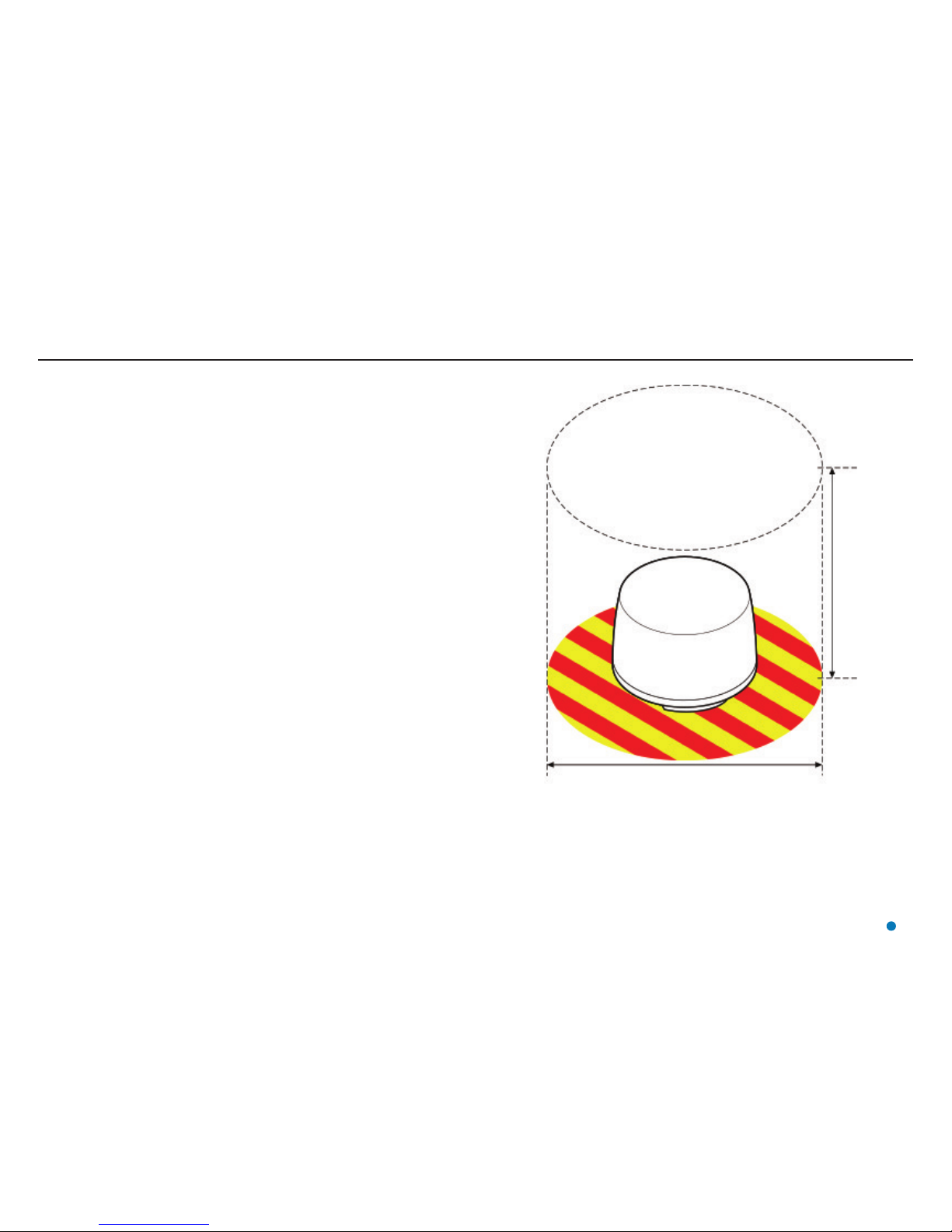
1000mm
800mm
Leave sufficient clearance around the sensor to allow access to
the cable connection plate.
Ensure that there is a clear line of sight to the Information Display
Screen. (See Sensor Information Display on page 24).
Leave sufficient
vertical clearance
to allow the
radome to be
removed.
11
Page 12
Mounting the Sensor (continued)
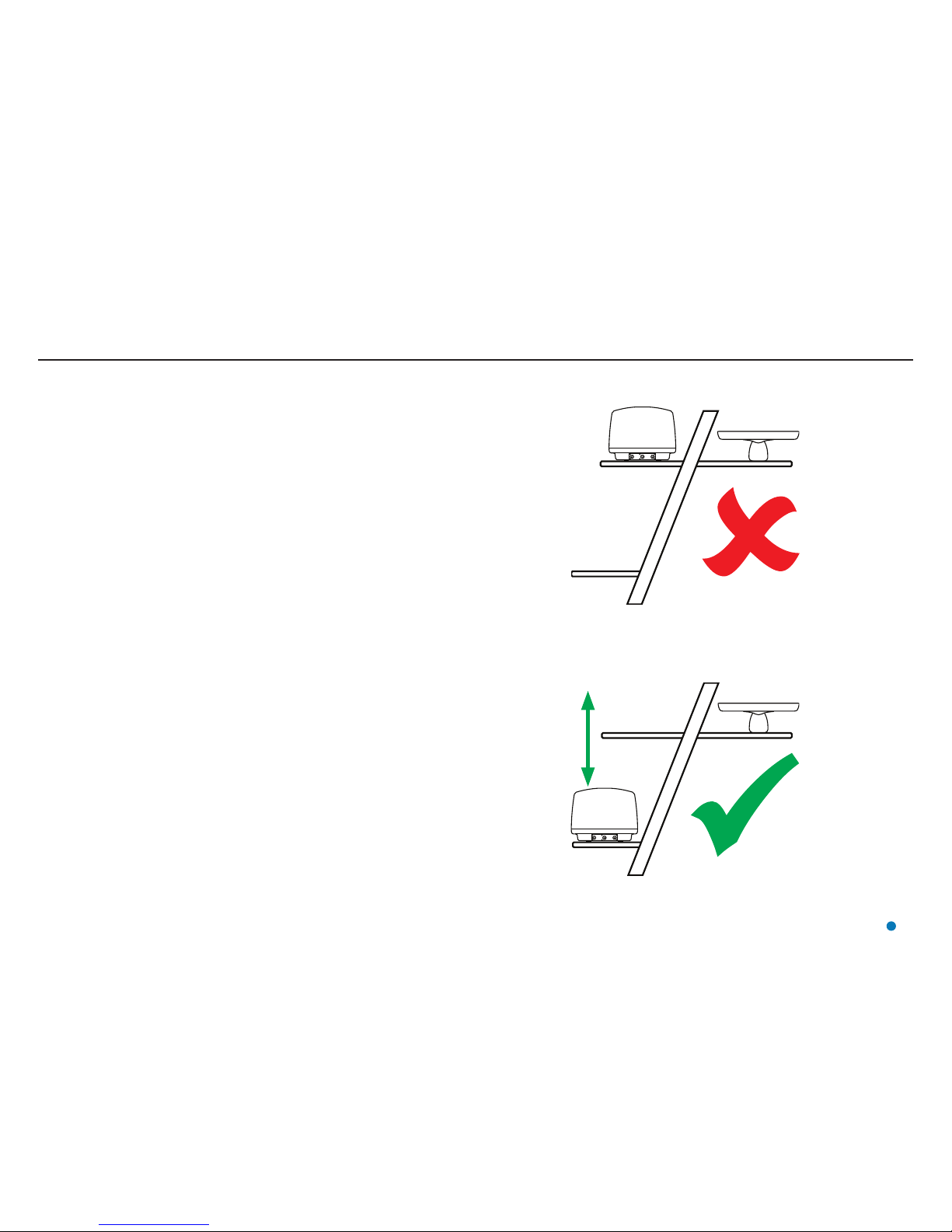
Avoiding Other Sources of Radiation
There should be as much vertical separation as possible between the RadaScan View Sensor and
any X-band radar or Artemis systems, to prevent the RadaScan View signal from being jammed.
Wherever possible, the RadaScan View Sensor should not be installed at the same vertical level as
an X-band radar or Artemis sensor.
If vertical separation of the two systems is impossible, they must be shielded from one another
with a metal screen. The screen must be large enough to physically shield the RadaScan View
sensor from the whole width of the x-band/Artemis antenna. In some cases, the vessel’s metal
superstructure may be used to provide part or all of the shielding between the two systems.
The RadaScan View Sensor does not need to be shielded from radar-based systems mounted on
other vessels or structures.
RadaScan
View
RadaScan
View
Incorrect—No Vertical Separation
Correct—Good Vertical Separation
X-Band Radar
X-Band Radar
12
Page 13
Mounting the Sensor (continued)
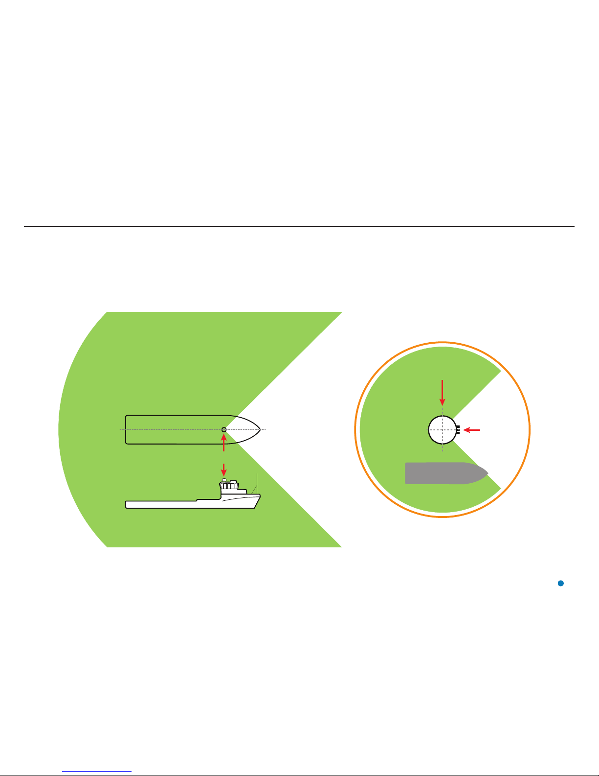
Operating Area Astern (e.g. PSV)
Mount the RadaScan View sensor with its connection panel facing towards the vessel’s bow.
(Connection panel faces away from the operating area).
The sensor’s position (Bow and Starboard Offsets) and orientation (Bearing Offset) must be set up
in the RadaScan Service Interface.
Operating
Area
RadaScan View Sensor
Operating
Area
Stern Bow
Connection
Panel
RadaScan View
Sensor
13
Page 14
Mounting the Sensor (continued)
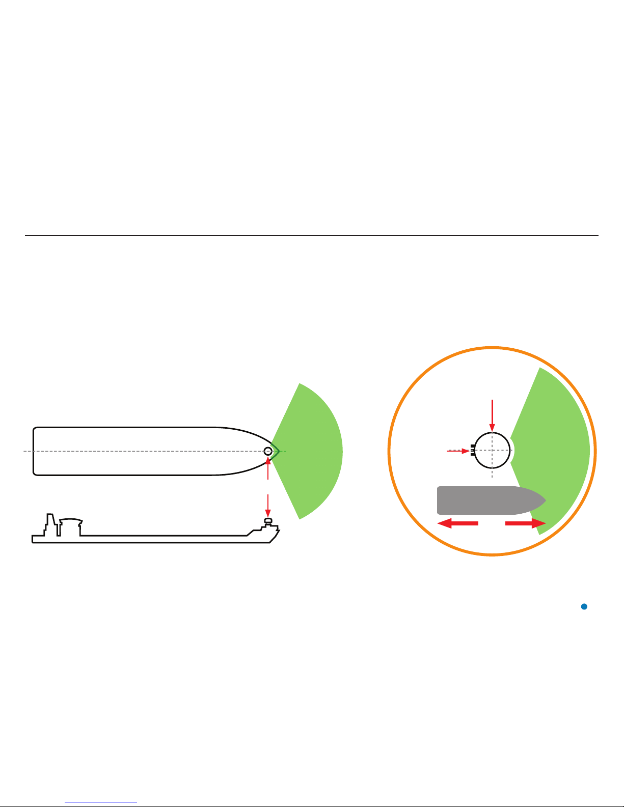
Operating Area Forward (e.g. Shuttle Tanker)
Mount the RadaScan View sensor with its connection panel facing towards the vessel’s stern.
(Connection panel faces away from the operating area).
The sensor’s position (Bow and Starboard Offsets) and orientation (Bearing Offset) must be set up
in the RadaScan Service Interface.
RadaScan View
Sensor
RadaScan View
Sensor
Connection
Panel
Operating
Area
Operating
Area
Stern Bow
14
Page 15
Mounting the Sensor (continued)
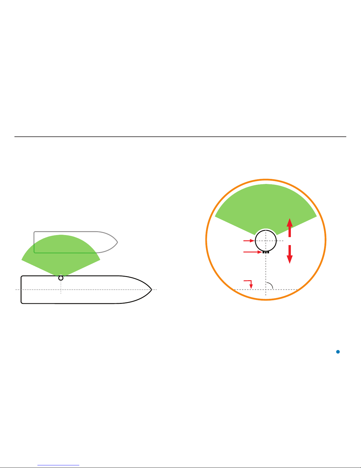
Operating Area to Port or Starboard (e.g. Track and Follow)
Mount the RadaScan View sensor with its connection panel facing inboard, towards the vessel’s centre line.
(Connection panel faces away from the operating area).
The sensor’s position (Bow and Starboard Offsets) and orientation (Bearing Offset) must be set up in the
RadaScan Service Interface.
a = angle from vessel’s centre line (See Bearing Offset on page 36).
RadaScan View Sensor
Responder Vessel
RadaScan View
Sensor
Connection Panel
Vessel
Centre
Line
a
Operating Area
Operating Area
Outboard
Inboard
15
Page 16
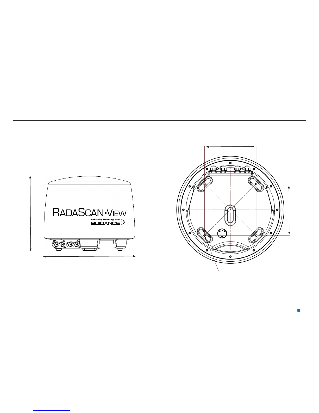
Sensor Dimensions
16
Bottom View
Ø 500mm
410mm
Side View
240mm
Mounting Holes
240mm
4XM8 MOUNTING HOLES
Page 17
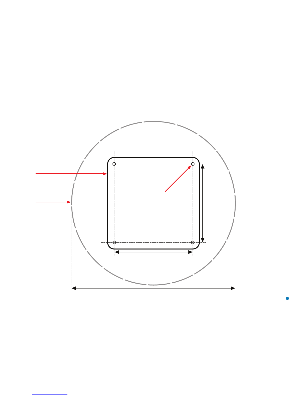
Mounting Template
240mm
500mm
240mm
Mounting Plate
NOT TO SCALE
Edge of
Radome
Four 9mm holes
(to take M8 bolts)
Ensure that any custom-made plinth is flat, rigid and
horizontal, able to support 25kg and to receive four M8
mounting bolts.
17
Page 18
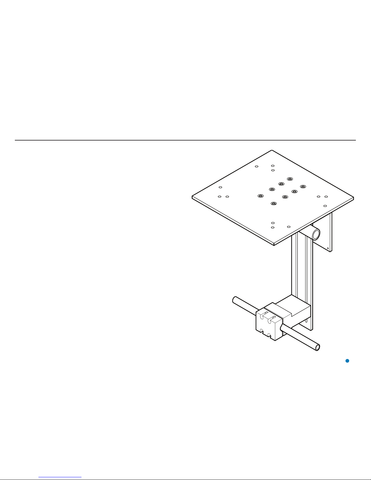
Universal Mounting Bracket
18
The Universal Mounting Bracket (Part No. 20-0120-1) can be used to mount the
RadaScan View sensor to a handrail or other suitable railing.
!
Ensure that the railing is strong enough to support the combined weight
of the sensor and bracket.
Page 19
19
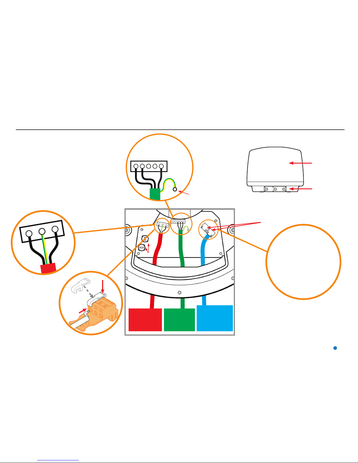
Sensor Connections—Direct
1
2
345
†See Network
Communication
Settings on page
32 or contact
Guidance Marine if
alternative settings
are required.
Default IP Addresses:†
RadaScan View Sensor:
192.168.2.231
Subnet Mask:
255.255.255.0
Marine Processor (LAN1):
192.168.2.241
Subnet Mask:
255.255.255.0
Radome
Connection Panel
Either Ethernet
socket may be
used
To Connect Cables to
Power/Serial Plugs:
Hook operation lever into
slot above connectorhole in plug.
Whilst holding down
lever, insert cable end
into connector-hole.
Release and remove
the operation lever.
TX +
TX −
RX −
RX +
GND
RS422 Link
9600 baud
8 bits
1 stop bit
No parity
!
The RadaScan View sensor installation should include a
double-pole disconnect device in the mains input wiring.
To Connect the Sensor:
1. Remove the radome and connection panel.
2. Feed the cables through the glands on the connection panel.
3. Connect the Ethernet, RS422 and Mains Power cables as
shown.
4. Lock the Ferrite Bead around the power cable as shown.
5. Apply DC4 silicone grease to the edge of the connection
panel, around the rim of the unit and into the cable glands.
6. Replace the connection panel and tighten the cable glands.
7. Replace the radome.
!
CAUTION
Double Pole/
Neutral Fusing.
Ethernet Link
to RadaScan
View Marine
Processor
RS422 Link
to Vessel’s
DP System
Mains Power
85–264V AC
45–65Hz 1.6A
Fuses
Fuse
Rating
250V T1.6A
(5 x 20mm)
CAT 5e
Cable
123
Live Earth Neutral
!
Sensor performance is
not guaranteed unless it
is properly earthed.
Attach cable screen
to DP earthing point
Page 20

Sensor Connections—Separate Connection Box
Live
Neutral
Earth
TXTX+
Signal GND
Signal GND
Screen
Earth
Lid and
Case Earth
1
2
3
6
1
2
3
6
Mains Power
85–264V AC
45–65Hz 45W
20
RS422 Link
to Vessel’s
DP System
Ethernet Link
to RadaScan
View Marine
Processor
RS422 Link
9600 baud
8 bits
1 stop bit
No parity
Default IP Addresses:†
RadaScan View Sensor:
192.168.2.231
Subnet Mask: 255.255.255.0
Marine Processor (LAN1):
192.168.2.241
Subnet Mask: 255.255.255.0
RadaScan View
Sensor
Connection
Box
Connection Box
Cables from
RadaScan
View Sensor
Power
DP Feed
Dashboard
Patch Cable
The Patch Cable can be disconnected at one end and
connected to a service laptop.
The laptop can then be used to check the Ethernet
link by ‘pinging’ either the Marine Processor or the
RadaScan View Sensor.
!
CAUTION
Double Pole/
Neutral Fusing.
!
The RadaScan View sensor
installation should include a
double-pole disconnect device
in the mains input wiring.
Fuse Rating:
2 x 250V T1.6A
(5 x 20mm)
CAT 5e Cable
CAT 5e Cable
†See Network
Communication Settings
on page 32 or contact Guidance
Marine if alternative settings are
required.
Page 21

Cable Routing Diagram - Direct Connection
Note: The Ethernet cable connecting
the Sensor to the Marine Processor
should not exceed 90 metres in
length.
Please contact Guidance Marine if
longer distances are required.
DP Instrument Room
Bridge
Mast
Emergency Breaker Box
Ethernet
Sensor Power
RS-422 Data
Monitor Cable
Monitor Power
Cable
Marine Processor
Power Cable
Power Cable
P/N 33-0121-3
(40m)
Data Cable
P/N 33-0451-3 (40m)
Ethernet Cable
P/N 33-0124-3 (40m)
16A
5A
5A
DP System UPS
DP System UPS
Interface Cabinet
RadaScan View
Sensor
Monitor
Link Cable
Dashboard
DP Feed
Power
Marine Processor
See page 23 for processor and monitor options
Power Adaptor
21
Page 22

Cable Routing Diagram - Separate Connection Box
Note: The Ethernet cable connecting
the Sensor to the Marine Processor
should not exceed 90 metres in
length.
Please contact Guidance Marine if
longer distances are required.
DP Instrument Room
Bridge
Mast
Emergency Breaker Box
Ethernet
Sensor Power
RS-422 Data
Monitor Cable
Monitor Power
Cable
Marine Processor
Power Cable
Power Cable
P/N 33-0121-3
(40m)
Data Cable
P/N 33-0451-3 (40m)
Ethernet Cable
P/N 33-0124-3 (40m)
16A
5A
5A
DP System UPS
DP System UPS
Interface Cabinet
RadaScan View
Sensor
Monitor
Link Cable
Dashboard
DP Feed
Power
Marine Processor
See page 23 for processor and monitor options
Power Adaptor
22
Connection
Box
Page 23

Cable Routing Diagrams - Processor and Monitor Options
Alternative Processor and Monitor Options
Any of the following configurations may be used (see pages 21, 22)
Processor: Type 3 Marine Processor (Part
Number 20-0231-0)
Monitor: 15” Desktop Monitor
(Part Number 20-0115-1)
Marine Processor
Desktop
Monitor
Monitor Power Cable
Monitor Cable
Power
Adaptor
Marine Processor
Power Cable
Marine Processor
Monitor Power Cable
Monitor Cable
Power
Adaptor
Marine Processor
Power Cable
Hatteland
Touchscreen
Monitor
Processor: Type 3 Marine Processor (Part
Number 20-0231-0)
Monitor: Hatteland Marine Touchscreen
Monitor (Part Number 20-0211-4)
Optional brackets: Hatteland Mounting
Bracket (Part Number 24-0259-4)
Hatteland VESA Bracket for Wall or Ceiling
(Part Number 24-0258-4)
Power Cable
Processor and Monitor: Hatteland
Panel PC (Integrated PC and Touchscreen
Monitor, Part Number 20-0182-1)
Optional brackets: Hatteland Mounting
Bracket (Part Number 24-0259-4)
Hatteland VESA Bracket for Wall or Ceiling
(Part Number 24-0258-4)
Hatteland
Panel PC
Ethernet
Ethernet
Ethernet
23
Page 24

Sensor Information Display
When the sensor has been powered up, the Sensor Information Display shows the sensor’s status
and network details. The display automatically cycles through the screens listed on the right. The
display cannot be paused. If the display sticks on one screen, the sensor should be restarted.
Information Display Location
The Sensor’s Information Display (VFD Screen) is on the side of the sensor, underneath the
radome:
Information Display Messages
Connection Status Indicators
The Connection Status Indicators are on the right-hand-side of the Information Display:
Information Display
ISO
TX
RX
5V
Isolated 5V Power
Ethernet Transmit
Ethernet Receive
5V Power
STATE: Idle
m, CPU: 2% RAM: 69MB
STATE: Idle
m, CPU: 2% RAM: 69MB
FPGA: 4.0.2.153
SERVER: 4.0.2.155
FPGA: 4..2.153
SERVER: 4..2.155
1: 00-50-C2-7A-7A-AD
IP: 192.168.2.231
1: -5-C2-7A-7A-AD
IP: 192.168.2.231
Sensor State
(Tracking or Idle)
Time since sensor powered up
CPU Usage
Network IP
Address
Server Version
FPGA Version
MAC Address
Second line: UpTime: xxd xxh xxm, CPU:xx% RAM: xxMB
Memory Usage
First line: LAN1: xx-xx-xx-xx-xx-xx
Each line of the Information Display is 20 characters in width. Messages that are wider than this
scroll from right to left.
24
Page 25

Sensor Information Display (continued)
When the sensor is booting, the Sensor
Information Display shows progress via the
following sequence of messages.
MiniRS booting...MiniRS booting...
Messages upon power-up
Operating System
Ver: 4.0.2.155
Operating System
Ver: 4..2.155
Starting Sensor
....
Starting Sensor
....
Resetting Done
....
Resetting Done
....
Host: Compact
Searching for IP -
Host: Compact
Searching for IP -
Host: Compact
IP: 192.168.2.231
Host: Compact
IP: 192.168.2.231
STARTING... BOOT: OK
IP: 192.168.2.231
STARTING... BOOT: OK
IP: 192.168.2.231
Second Stage boot
Ver: 4.0.2.155
Second Stage boot
Ver: 4..2.155
Operating System
Ver: 4.0.2.155
Operating System
Ver: 4..2.155
Starting Sensor
....
Starting Sensor
....
A self-test is run. If this fails and a reboot
takes place, the following messages are
also seen:
If any of the following messages are displayed, take the action stated.
Troubleshooting
Cause: Missing SD card.
Action: Contact Guidance Marine.
No SD card image
Booting via Ethernet
No SD card image
Booting via Ethernet
Cause: SD card error.
Action: Contact Guidance Marine.
SD card Error
Rebooting
SD card Error
Rebooting
Cause: Missing server application.
Action: Reinstall the sensor software
(see page 26).
No Application
Run remote install
No Application
Run remote install
Cause: Server problem.
Action: Reinstall the sensor software (see page 26).
Application failed
Loading Backup
Application failed
Loading Backup
25
Page 26

Your RadaScan View sensor will have been shipped from Guidance Marine with software
already installed. However, it may be necessary from time to time to upgrade the software
with a newer version.
To
Upgrade the Sensor Software:
1. Locate the RadaScan.Installer.Remote.exe file on the USB memory stick on which it
was supplied.
2. Double-click on the RadaScan.Installer.Remote.exe file.
The RadaScan Installation Configuration screen is displayed.
3. If the IP Address shown is not correct for your sensor, amend it.
4. Click on OK.
After a couple of minutes, if the installation is successful, the RadaScan Installation
Summary screen shows “Installation Complete”.
If you needed to amend the IP Address in step 3, follow the instructions in Network
Communication Settings on page 32.
If there are problems during the installation, refer to the file InstallLog_<Date_Time>.txt,
which can be found at the same location as the RadaScan.Installer.Remote.exe file.
RadaScan Installation
Configuration Screen
RadaScan Installation
Summary Screen
26
Installing the Sensor Software
In the unlikely event that the installation has become corrupted, contact Guidance Marine
or an approved service representative.
Page 27

27
Before setting up the RadaScan View client computer(s), refer to the relevant installation sheet(s) for
dimensions and connection information:
For a Type 3 Marine Processor:
•
94-0465-4 Type 3 Marine Processor and Display Installation Sheet
For a Hatteland Panel PC:
•
94-0466-4 Hatteland Panel PC Installation Sheet
The following pages explain how to install the client software:
•
Installing RadaScan Client Software onto a Type 3 Marine Processor (page 28)
•
Installing RadaScan Client Software onto other Types of Computer (page 29)
Installing the Marine Processor
Page 28

Installing RadaScan View Client Software onto a Type 3 Marine Processor
This section explains how to install the RadaScan View client software onto a Type 3 Marine Processor.
If this Marine Processor has been supplied by Guidance Marine, it will have been shipped with the client
software already installed. However, it may be necessary to upgrade the software with a newer version. If
so, first uninstall the existing software in the usual way, following on-screen prompts.
To Install the Dashboard:
1. Locate the RadaScanDashboardSetup.exe and RadaScanServiceInterfaceSetup.exe files on the
USB memory stick on which they were supplied.
2. Double-click on the RadaScanDashboardSetup.exe file.
The Welcome screen is displayed.
3. Click on the Install button.
4. When prompted, click on the Restart button.
After the restart, the RadaScan Dashboard Setup screen is displayed.
5. If required, change any of the settings from the default values shown.
6. Click on the OK button.
7. When prompted, click on the Restart button.
The installation process is complete following the restart.
8. Repeat steps 2..7 for RadaScanServiceInterfaceSetup.exe.
Welcome Screen
RadaScan Dashboard Setup Screen
Setup Successful Screen
!
NOTE: The RadaScan
Service Interface should
only be installed onto one
computer in the system.
The Dashboard may be
installed onto multiple
computers.
Conguration Settings
When installing the Dashboard, adjust the following setings or allow to default:
Communications Parameters
Ensure that the sensor’s IP address is shown, otherwise enter “127.0.0.1” in order to run the Dashboard
with a RadaScan Emulator on the same computer.
Display
If the Enable Dashboard On-Screen Keyboard box is ticked, the OSK will pop up when you focus on a
text or numerical entry field (typically used on a system without a keyboard).
Data Logging
The Minimum Free Disk Space (Mb) field defines an amount of disk space that the Dashboard will leave
free when writing log files. The Dashboard automatically begins to trim log data when the disk space falls
below a threshold determined by [Minimum Free Disk Space (Mb) + Additional Free Disk Space
Buffer (Mb)].
28
Page 29

Installing RadaScan View Client Software onto other Types of Computer
This section explains how to install the RadaScan View client software onto a computer running Windows 7
that does not have a File-Based Write Filter. This PC should have the following installed:
•
Full .NET Framework 4.0 or later
•
Visual C++ 2012 Redistributable (x86)
If you are upgrading to newer versions of the RadaScan View client software, first uninstall the existing
versions in the usual way, following on-screen prompts.
To Install the Dashboard:
1. Locate the RadaScanDashboardSetup.exe and RadaScanServiceInterfaceSetup.exe files on the
USB memory stick on which they were supplied.
2. Double-click on the RadaScanDashboardSetup.exe file.
The Welcome screen is displayed.
3. Click on the Install button.
The RadaScan Dashboard Setup screen is displayed.
4. If required, change any of the settings from the default values shown.
5. Click on the OK button.
When the installation has finished, the Setup Successful screen is displayed.
6. Click on the Close button.
7. Repeat steps 2..6 for RadaScanServiceInterfaceSetup.exe.
Welcome Screen
RadaScan Dashboard Setup Screen
Setup Successful Screen
!
NOTE: The RadaScan
Service Interface should
only be installed onto one
computer in the system.
The Dashboard may be
installed onto multiple
computers.
29
Page 30

Conguring the RadaScan View System
30
This section contains the following pages:
•
Using the RadaScan Service Interface (page 31)
•
Network Communication Settings (page 32)
•
Vessel Definition (page 34)
•
Blanking Zone (page 38)
•
DP Feed Configuration (page 39)
•
Information Tabs (page 41)
Page 31

Using the RadaScan Service Interface
The RadaScan Service Interface (RSI) is a tool for configuring the RadaScan View system.
To open the RadaScan Service Interface
Ensure that the sensor is powered on and connected to the control computer.
1. Double-click on the RSI icon:
(Alternatively, run from the Start menu:
Start > All Programs > Guidance Marine Ltd > RadaScan > RadaScan Service Interface).
Screen Layout of the RSI
The upper part of the RSI window contains fields relating to communications, as follows:
Take Command / Relinquish Command – This button allows the user to toggle the command
mode of the RSI between In Command and Monitoring.
Connect – Replaces Take Command / Relinquish Command when the RSI is disconnected from
the sensor, allowing re-connection.
Resume - Replaces Take Command / Relinquish Command when the sensor is suspended,
allowing it to be resumed.
In Command Indicator – This red block symbol is visible when the RSI is In Command mode.
Status Display – Indicates the current status of the system, e.g. “System Running Normally” or
“System Suspended”.
Activity Wheel – A green rotating animation when the RSI is connected to the sensor; green and
stationary when disconnected; red and stationary if there is an error condition.
The remainder of the RSI screen is occupied by one of several tab areas.
The Status Tab
The Status tab gives an overview of the operational state of the system; it contains the following
fields and control buttons:
Connected State – Whether the RSI is “Connected” to the sensor or “Disconnected”.
Sensor State - “Running” or “Suspended” when the RSI is connected; “Unknown” when not
connected.
Suspend / Resume – Allows the sensor to be suspended when running or resumed when
suspended; enabled only when the RSI is In Command. Displays “---“ when not connected.
Sensor Type – “Mini”, “Mini with Radar Image” or “Maxi” if the RSI is connected to a physical
sensor, “Emulator” if connected to the RadaScan Emulator application or blank if not yet
connected.
Tracking State – “Not Tracking”, “Starting Tracking” or “Tracking”.
#Tracked Targets – How many targets are being tracked, including any that are rejected or
obscured. Displays “N/A” when tracking is not in progress.
Last Time Feedback Received – In hh:mm:ss format; updated once per second. Blank when
the RSI is not connected.
Reboot Sensor – Enabled only when the RSI is in command mode and tracking is not in
progress.
31
Page 32

Network Communication Settings
The Network Config tab of the RSI is used to view and amend the RSI’s record of the sensor’s
network IP address and also to remotely amend the address on board the sensor.
The network IP address is displayed on the Sensor Information Display (see page 24).
!
NOTE: Where the Dashboard and RSI are installed on the same computer, they share a
common record of the sensor’s network IP address. If it is amended using one application,
the other picks up the change when next opened.
To Modify the RSI’s Record of the Sensor’s Network IP Address
1. Click on the Network Config tab of the RSI.
2. Click on the Disconnect button if the RSI is connected to the sensor.
3. Click on the Edit button in the Service Interface to Sensor Communications section.
4. Amend the Sensor Address as required.
5. Click on Apply to save the changes or on Cancel to discard.
To Modify the Dashboard’s Record of the Sensor’s Network IP Address
1. Click on the Guidance button to open the Guidance Home menu.
2. Unless the Dashboard is already in Monitoring mode, click on Relinquish Command.
3. Click on Disconnect.
4. Navigate to Advanced > Comms Settings.
5. Click on Edit.
6. Amend the Address field as required.
7. Click on the Apply button to confirm.
32
Page 33

Network Communication Settings (continued)
To Remotely Modify the Sensor’s On-Board Network IP Address
1. Ensure that the RSI is in command and that no tracking is in progress.
2. Click on the Network Config tab of the RSI.
3. Click on the Edit button in the Sensor On-Board Network Configuration section.
4. Amend the Sensor Address as required.
5. Click on Apply to save the changes.
Communications between the RSI and sensor are then lost as the sensor is rebooted. After a
minute or two, the Rebooting pop-up window is replaced by Reboot Request Succeeded. Click
on the OK button to return to normal operation.
33
Page 34

Vessel Denition
The Vessel tab allows you to define the dimensions of the vessel outline on the Bird’s Eye
View of the Dashboard, the name of the vessel and other items as follows:
•
Vessel Name: The name of your ship. This is displayed beneath the primary system
status near the top right corner of the Dashboard screen.
•
Vessel Length: The distance from the bow to the stern of the vessel, in metres.
•
Vessel Breadth: The width or beam of the vessel in metres.
•
Bow Offset: Distance from the centre of the RadaScan View sensor to the vessel’s bow,
in metres.
•
Starboard Offset: Distance from the centre of the sensor to the vessel’s starboard side,
in metres.
•
Bearing Offset: This should be 0° if the sensor is facing aft, mounted exactly parallel
to the vessel’s centre-line running from bow to stern. If the sensor is at a slight angle
to the centre-line, enter a positive or negative Bearing Offset to compensate for this.
See Bearing Offset on page 36 for the value to use if the sensor is facing in another
direction.
•
Display Vessel Orientation: The default direction of the vessel bow as displayed on
the Dashboard BEV. Changing this setting rotates the whole BEV but does not affect
the data sent to the DP system. Note that this setting can be overridden for the current
Dashboard session via Advanced > Display Options > Screen Layout, but the BEV
reverts to the default orientation when the Dashboard is closed and re-opened.
.
Modifying Vessel Definition
In order to amend any of the above parameters:
1. Click on the Take Command button if the RSI is not already in command mode.
2. On the Vessel tab, click on the Edit button.
3. Amend the vessel definition as required.
4. Click on Apply to save the changes or on Cancel to discard.
34
Page 35

Vessel Denition (continued)
Starboard Offset
Bow Offset
RadaScan
View Sensor
Port Side Starboard Side
Bow and Starboard Osets
Enter the correct Bow and Starboard Offset values on the Vessel tab
(See Vessel Definition on page 34)
35
Page 36

Vessel Denition (continued)
RadaScan View
Sensor
Vessel Centre-line
Connection
Panel
Operating
Area
Sensor Facing Aft
Connection panel facing forward,
Sensor parallel with vessel centre-line.
Bearing Offset = 0°
Sensor Facing Forward
Connection panel facing aft,
Sensor parallel with vessel centre-line.
Bearing Offset = 180°
Sensor Facing Port
Connection panel facing starboard,
Sensor perpendicular to vessel
centre-line.
Bearing Offset = 90°
Sensor Facing Starboard
Connection panel facing port,
Sensor perpendicular to vessel centre-line.
Bearing Offset = −90°
180°
−90°
90°
0°
Key
Bearing Oset
Enter the correct Bearing Offset value on the Vessel tab
(See Vessel Definition on page 34)
•
If the sensor is facing directly Aft,
enter a 0° bearing offset.
•
If the sensor is facing directly Forward,
enter a 180° bearing offset.
•
If the sensor is pointing to Port,
enter a Positive bearing offset, e.g. 90°
•
If the sensor is pointing to Starboard,
enter a Negative bearing offset, e.g. −90°.
36
Page 37

Vessel Denition (continued)
Reset, Import and Export of Vessel Denition
The Vessel Definition can be reset to factory defaults, imported from an XML or CTF file or
exported to an XML file.
To Reset to Factory Defaults:
1. Ensure that no target tracking is in progress.
2. Click on the Take Command button if the RSI is not already in command mode.
3. On the Vessel tab, click on the Defaults button.
To Import Vessel Definition from a File:
1. Ensure that no target tracking is in progress.
2. Click on the Take Command button if the RSI is not already in command mode.
3. On the Vessel tab, click on the Import button.
4. Locate the required .xml or .ctf file in the file browser window.
5. Click on the Open button.
To Export Vessel Definition to a File:
1. Ensure that no target tracking is in progress.
2. Click on the Take Command button if the RSI is not already in command mode.
3. On the Vessel tab, click on the Export button.
4. Specify a destination and file name in the file browser window.
5. Click on the Save button.
37
Page 38

Blanking Zone
A Blanking Zone can be used to mask the segment of the scan rotation that is obscured by the
vessel’s superstructure. The start and end of the zone can be set to any positions around the circle
to the nearest degree.
Generally, once the blanking zone has been set, it will not need to be changed.
!
The option to change the blanking zone
is not available whilst tracking.
To Dene a Blanking Zone
1. Ensure that no target tracking is in progress.
2. Click on the Take Command button if the RSI is not already in command mode.
3. On the Blanking tab, click on the Edit button.
4. Amend the blanking zone Start and Stop fields as necessary (if you wish to delete a zone,
set Start and Stop to the same value).
5. Click on Apply to save the changes or on Cancel to discard.
38
Page 39

DP Feed Conguration
The RadaScan View system provides positional data messages to your vessel’s DP (Dynamic
Positioning) system and the format and behaviour of this output stream needs to meet the
requirements of the DP system.
The current DP configuration settings are displayed on the DP Config tab of the RSI, along with
the data output relating to the primary (or only) target. See DP Message Types (page 54) for
details of each available message format and DP Feed Behaviour (see right) for the function of
the Keep Feed Enabled and Allow Zero Strings tick-boxes.
Modifying the DP Conguration
1. Ensure that no target tracking is in progress.
2. Click on the Take Command button if the RSI is not already in command mode.
3. On the DP Config tab, click on the Edit button.
4. Amend the settings as required.
5. Click on Apply to save the changes or on Cancel to discard.
DP Feed Behaviour
The DP Feed Behaviour options are two tick-boxes available on the DP Feed pane in Service
Access Mode:
Keep DP feed always enabled
Allow refresh timer & zero strings
These determine what data is sent to the DP system if a target is lost during tracking. Also when
the system is running but not tracking, or is suspended.
The DP Feed Behaviour settings must be set correctly for the vessel’s DP system. Incorrect
settings can cause serious problems. Refer to the vessel’s DP system supplier for the
required configuration.
The following behaviour applies when target tracking:
For all DP formats except for MT Custom:
Keep Feed
Enabled
Allow Zero
Strings
Output when tracking and target is lost
Null data (gaps in data string)
Null data (gaps in data string)
Zero data (coordinates set to zero, status = V †)
Zero data (coordinates set to zero, status = V †)
For the MT Custom DP format, Zero data (coordinates set to zero, status = V) is output when the
target is lost. The DP Feed Behaviour options have no effect.
Keep Feed
Enabled
Allow Zero
Strings
Output when target is visible but not tracked
Null data (gaps in data string)
Void data (actual coordinates but status = V)
Zero data (coordinates set to zero, status = V)
Void data (actual coordinates but status = V)
† Denotes that not all of these DP formats include a Status field, but for those that do, it is set to
“V”.
The following behaviour applies whilst the system is operational but not tracking:
For NMEA Raw and NMEA Primary DP formats:
39
Page 40

For Rolls Royce Custom DP format:
Keep Feed
Enabled
Allow Zero
Strings
Output when target is visible but not tracked
Null data (gaps in data string)
Available data (actual co-ordinates, status = A)
Zero data (coordinates set to zero, status = V)
Available data (actual co-ordinates, status = A)
For the MT Custom DP format, Available data (actual co-ordinates, status = A) is output when a
target is visible but not tracked. The DP Feed Behaviour options have no effect.
The following behaviour applies when the system is suspended:
For all DP formats except for MT Custom:
Keep Feed
Enabled
Allow Zero
Strings
Output when system is suspended
Null data (gaps in data string)
Null data (gaps in data string)
Zero data (coordinates set to zero, status = V †)
Zero data (coordinates set to zero, status = V †)
DP Feed Conguration (continued)
For the MT Custom DP format, Zero or Stale data (coordinates set to zero or to previous known
values, status = V) is output when the system is suspended. The DP Feed Behaviour options
have no effect.
† Denotes that not all of these DP formats include a Status field, but for those that do, it is set
to “V”.
For MDL Standard, MDL Multi-Target and Kongsberg Standard DP formats:
Keep Feed
Enabled
Allow Zero
Strings
Output when target is visible but not tracked
Null data (gaps in data string)
Null data (gaps in data string)
Zero data (coordinates set to zero)
Zero data (coordinates set to zero)
40
Page 41

Information Tabs
The RSI contains several tabs that contain read-only information about the RadaScan View
system.
The Clients Tab
This lists each Dashboard currently connected to the RadaScan View sensor, in addition to the
RSI itself. It gives the command mode and computer name of each.
The Alarms Tab
This lists each sensor-based alarm event that has occurred since the RSI was opened. Alarms
sourced in the Dashboard are not included. Note that there are separate entries for starting and
stopping the same alarm, unlike the Dashboard Alarms pane which gives start and stop times on
one line.
41
Page 42

Information Tabs (continued)
The About Tab
This contains version information for the RSI and sensor, the serial number of the sensor, contact
details for Guidance Marine Ltd and a button for opening an on-screen copy of this Installer’s
Guide.
42
Page 43

This section explains how to install and maintain RadaScan View Responders.
It contains the following pages:
•
Responder Overview (page 44)
•
Positioning Responders (page 46)
•
Mounting Responders (page 47)
•
Charging Responders (page 49)
•
Operating Responders (page 50)
Installing Responders
43
Page 44

Responder Overview
Series 2 and 3 Responders can be used with RadaScan and RadaScan View systems. One or
more Responders should be mounted on the target platform or vessel.
The following models of RadaScan Series 2 Responder are no longer available but may be
encountered in the field.
•
Rechargeable (Part No. 20-0108-1)
•
Rechargable - Low Temperature (Part No. 20-0108-L-1)
•
Primary Cell Responder (Part No. 20-0138-1)
The Primary Cell Responder is powered by a Primary Cell Pack (Part No. 21-0314-1). This
requires battery replacement as routine maintenance. This should be undertaken by Guidance
Marine, or by a suitably qualified service technician.
There are four models of RadaScan Series 3 Responder:
•
Rechargeable (Part No. 20-0189-2)
•
Mains Powered (Part No. 20-0195-2)
•
Primary Cell Responder (Part No. 20-0194-2)
•
Narrow Beam Primary Cell Responder (Part No. 20-0196-2)
The Mains Powered Responder is used with Responder AC/DC power supply (Part No.
21-0377-2).
Both types of Primary Cell Responder are powered by a Primary Cell Pack (Part No. 21-0375-
1). This requires battery replacement as routine maintenance. This should be undertaken by
Guidance Marine, or by a suitably qualified service technician.
!
Do not open the Responder. It should only
be serviced by Guidance Marine,
or a suitably qualified service technician.
If you experience any problems with the unit,
please contact:
Guidance Marine Ltd
5 Tiber Way
Meridian Business Park
Leicester
LE19 1QP
United Kingdom
Tel: +44 116 229 2665
Email: customerservices@guidance.eu.com
RadaScan Series 2
Responder
ATEX Certification Label (for illustration
purposes – actual label may be
formatted differently)
RadaScan Series 3
Responder
44
Page 45

Instructions for Safe Selection, Installation, Use, Maintenance, Repair and
Transport
User instructions (in compliance with ATEX 94/9/EC Directive, Annex II, 1.0.6)
Unit Part No. Temperature Range ATEX Certification No.
Series 2
Rechargeable 20-0108-1 -25°C to +55°C SIRA 11ATEX2254X
Rechargeable 20-0108-L-1 -40°C to +55°C SIRA 11ATEX2254X
Primary Cell Responder 20-0138-1 -40°C to +55°C SIRA 11ATEX2286X
Primary Cell Pack 21-0314-1 -40°C to +55°C SIRA 11ATEX2286X
Series 3
Rechargeable 20-0189-2 -40°C to +55°C SIRA 15ATEX2015X
Mains Powered 20-0195-2 -40°C to +47°C SIRA 15ATEX2047X
Primary Cell Responder 20-0194-2 -40°C to +55°C SIRA 15ATEX2048X
Narrow Beam Primary
20-0196-2 -40°C to +55°C SIRA 15ATEX2048X
Cell Responder
Primary Cell Pack 21-0375-1 -40°C to +55°C SIRA 15ATEX2048X
Use in Hazardous Environments
•
Series 2 responders and primary cell packs may be used in zones 1 or 2 with flammable gases.
•
Series 3 responders and primary cell packs may be used in zones 0, 1 or 2 with flammable
gases.
•
All Series 2 and 3 responders and primary cell packs may be used in the presence of flammable gases
and vapours with apparatus groups IIB or IIA and with temperature classes T1 or T2 or T3 or T4.
•
The equipment is certified for use in ambient temperatures in the applicable range shown above and
should not be used outside this range.
Installation and Maintenance
•
Responders must be installed by suitably trained personnel in accordance
with the applicable code of practice (typically IEC EN 60079-14).
•
Responders must be inspected regularly by suitably trained personnel in accordance
with the applicable code of practice to ensure they are maintained in a satisfactory condition.
•
Responders are not intended to be repaired by the user. They must only be repaired or serviced by
Guidance Marine, or by an approved service representative of Guidance Marine, in accordance with
the applicable code of practice.
•
Responders do not require assembly or dismantling.
They do not contain any customer-replaceable parts, and no user adjustment is required.
Responder Overview (continued)
Responder Colours
Each Series 2 or 3 Responder uses one of four different modulation frequencies. These are
characterised as colours: Red, Yellow, Green and Blue. The colour of a responder is clearly
marked on the outside of its case, and is shown next to its ID number on the Reflections and
Extended Information panes of the Dashboard.
This scheme makes it easier for the RadaScan View system to separate the signal from one
responder from the signal from a responder of a different colour. If you use more than one
responder at once, then for best results make sure that you use a different colour for each
responder.
Electrostatic Hazard
•
Responders must not be installed where external conditions could cause an electrostatic build-up
on their outer casing.
•
The Responder’s outer casing presents a static hazard and must only be cleaned using a damp
cloth.
Corrosive Substances
•
Responders should be protected from solvents, or acidic gases or liquids that may affect the
integrity of the outer case.
Transport
•
Responders must be transported in a suitable transit case.
45
Page 46

Positioning Responders
The location, range and orientation of the Responders in relation to the Sensor have a significant
effect on the tracking performance of the RadaScan View system, and hence on the quality of the
position data sent to the DP system.
The RadaScan View system is based on radar technology. Metallic structures reflect the
microwave beam transmitted by the sensor, and can cause multipath interference, where ghost
images are reported by the system. However, this unwanted phenomenon can be prevented by
carefully positioning the responders according to the following guidelines:
Responders Should be Mounted:
With a clear, unobstructed view towards the RadaScan View-equipped vessel.
At a height no lower than two metres below the vessel-mounted Sensor.
At a height no higher than five metres above the vessel-mounted Sensor.
On outside corners of the rig or platform to minimise the amount of
metallic structure around them.
Good Location
Good angle of incidence.
Lower angle of elevation allows
vessel to pick up responder on
approach.
Longer range aids performance
in high sea states.
Usually clear of obstructions
and away from enclosed corners.
Provides adequate cover
during vessel manœuvres.
R
Rig/Platform RadaScan View Vessel
Good
Responder
Locations
Poor Location
Good angle of incidence.
Steep angle of elevation prevents
vessel from picking up responder
on approach.
Shorter range inhibits performance
in high sea states.
Often surrounded by obstructions
and radar-reflecting metalwork.
Does not provide adequate cover
during all vessel manœuvres.
R
Rig/Platform RadaScan View Vessel
Poor
Responder
Location
Responders Should NOT be Mounted:
On inside corners.
Below an overhang.
On lower service decks below a main-deck overhang.
Suspended from a lanyard or length of rope.
46
Page 47

Mounting Responders
Loosen the nut to swivel the
bracket in the required direction.
!
Tighten the nut with a
spanner to fix the bracket’s
position.
The responder can be used with or without a swivel bracket, as
long as it is mounted with its longest side vertical, and its carryinghandle at the top.
To Mount the Responder:
1. Hook the foot of the responder underneath the knob on the
bottom of the mounting plate. (See below).
2. Rotate the responder backwards until it is held in place by its
magnet against the mounting plate.
3. (Optional) Attach safety lanyard onto the responder and the
swivel bracket or other fixture.
Knob
Mounting
Plate
Magnet
Swivel Bracket
The swivel bracket (Part No. 21-0328-1) should be used to point
the responder towards the RadaScan View Vessel’s working area.
It can be mounted on either a horizontal or vertical bar:
Swivel Bracket
Mounting on Horizontal Bar Mounting on Vertical Bar
Swivel Bracket
47
Page 48

Mounting a Primary Cell Responder
with a Primary Cell Pack:
Mounting Responders (continued)
Responder Swivel-
bracket with 2 x U-bolts
Primary cell pack bracket
(Part No. 21-0340-1)
with 2 x thumb screws
Bracket tail to provide
additional support
Primary Cell Pack
(Part No. 21-0314-1 for Series 2
or 21-0375-1 for Series 3)
Lanyard attachment points
48
Page 49

Charging Responders
The rechargeable responder should be fully charged before use.
A full charge takes approximately 24 hours.
!
DO NOT charge responders in an explosive
atmosphere or other hazardous environment.
The responder should be switched off while charging.
To Charge the Responder:
!
Note: Only use the supplied charger. Only charge at ambient temperatures of 0°C to
+45°C.
1. Switch the responder off and unscrew the charging socket cap on the rear of the unit.
2. Connect the supplied mains charger (Part No. 39-0049-2).
(Input: 100–240VAC, 50–60Hz, 1.5A Output: 24VDC, 2.5A, 60W).
3. When charging is complete, disconnect the power from
the unit and replace the charging socket cap.
Rechargeable Responder—Rear
Charging
Socket
49
Page 50

Operating Responders
The responder must always be used with its longest side vertical,
and its carrying handle at the top.
Switch the unit off when not in use to preserve the battery.
!
The responder is water resistant.
However, do not submerge the unit in water.
To Switch the Responder ON:
•
Press the ON/OFF button at the top of the unit.
•
For a rechargeable responder, the green light in the centre of the
button indicates how much battery charge is remaining (assuming
24/7 operation):
Light solidly on Up to 22 days left
1 flash in 5 seconds Up to 10 days left
3 flashes in 5 seconds Up to 1 day left
•
For a mains powered responder, the light should flash with an
interval of 5 seconds.
•
For a primary cell responder, the light indicates the state of the
primary cell pack:
1 flash in 5 seconds PCP normal
3 flashes in 5 seconds PCP low
Under normal conditions, the primary cell responder will operate for up
to one year before the batteries need replacing.
!
When a rechargeable responder is switched on and the green
light is not illuminated, recharge the battery.
!
When a primary cell responder is switched on and the green
light does not flash at all, replace the primary cell. The batteries
within the primary cell may be replaced, but this must only be
done in an ATEX safe environment, using batteries supplied by
Guidance Marine or authorised partners.
ON/OFF Button
50
Page 51

This section contains the following appendices:
•
International Standards Compliance (page 52)
•
Part Numbers (page 53)
•
DP Message Types (page 54)
•
UPS and Cable Specifications (page 58)
•
Installation Checklist (page 59)
•
Index (page 61)
Appendices
51
Page 52

International Standards Compliance
RadaScan View Transceiver
European Union
The equipment is permitted to be used in all EU member states
without the need for a specific administrative licence.
The RadaScan View X-band Transceiver meets the requirements of Directive 2004/108/EC.
The equipment complies with EN 60945:2002.
Norway
Note that in Norwegian waters a maritime radio licence is required for
the use of the RadaScan View Dynamic Positioning Sensor.
Please contact Telenor Maritime Radio to obtain a licence:
Telenor Maritime Radio
Radio Licensing Department
N-1331 FORNEBU
NORWAY
Tel: +47 22 77 43 50
Fax: +47 22 42 70 72
Web: www.maritimradio.no
USA
Use of the RadaScan View system in the United States of America is authorised
by the Federal Communications Commission. FCC ID: VYMRADASCAN.
RadaScan Responders
EU ATEX Directive 94/9/EC, Annex II, 1.06
RadaScan responders are certified as intrinsically safe and can be used with flammable gases and
vapours belonging to gas groups IIA/B.
Series 2 responders can be used in zones 1 and 2.
Series 3 responders can be used in zones 0, 1 and 2.
US
(See page 45)
52
Page 53

Sensor
Component Part Number
RadaScan View Sensor 20-0174-0
Universal Mounting Bracket 20-0120-1
Guidance Marine System Level USB 180-0011-4
Operator’s Guide 94-0491-4
Installer’s Guide 94-0492-4
Marine Processor
Component Part Number
Type 3 Marine Processor 20-0231-0
Hatteland Panel PC 20-0182-1
Cables
Component Part Number
Power Cable (40m) 33-0121-3
Data Cable (40m) 33-0451-3
Ethernet Cable (40m) 33-0124-3
Ethernet Connector Plug 80-0075-4
Part Numbers
Responders
Component Part Number
Series 2
Responder (Rechargeable) 20-0108-1
Responder (Rechargeable) 20-0108-L-1
Primary Cell Responder 20-0138-1
Primary Cell Pack 21-0314-1
Recharger 39-0033-2
Series 3
Responder (Rechargeable) 20-0189-2
Responder (Mains Powered) 20-0195-2
Primary Cell Responder 20-0194-2
Narrow Beam Primary Cell Responder 20-0196-2
Primary Cell Pack 21-0375-1
PCP Interface cable 33-0392-3
Recharger 39-0049-2
Mains Power Supply 21-0377-2
Mains PSU Interface Cable 33-0395-3
Lanyard 24-0260-2
Common
Swivel Bracket 21-0328-1
Primary Cell Bracket 21-0340-1
53
Page 54

NMEA Raw Format
A 42-character string:
$RLS,±AAA.AA,±BBB.BB,S1,XXX.XXX,S2,HHHH*CC<CR><LF>
Where:
•
$RLS message header
•
AAA.AA resolved raw position in A axis [metres]
•
BBB.BB resolved raw position in B axis [metres]
•
S
1
status of position data in A and B axis, [A] available; [V] void
•
XXX.XXX resolved heading of vessel with respect to A axis [degrees]
•
S
2
status of bearing data, [A] available; [V] void
•
HHHH status word in hexadecimal. Up to 16 bits defined by Guidance Marine in a separate
specifications document
•
CC computed checksum in hex
•
<CR> Carriage return (ASCII 0D hex)
•
<LF> Line feed (ASCII 0A hex)
!
Note: Although NMEA Raw and NMEA Primary share the same syntax, they produce different
values for AAA.AA and BBB.BB for a given layout of responders and are therefore not
interchangeable. The message type selected on the Dashboard must always match the
message type selected on the vessel’s DP system.
NMEA Primary Format
A 42 character string:
$RLS,±AAA.AA,±BBB.BB,S1,XXX.XXX,S2,HHHH*CC<CR><LF>
Where:
•
$RLS message header
•
AAA.AA resolved primary position in A axis [metres]
•
BBB.BB resolved primary position in B axis [metres]
•
S
1
status of position data in A and B axis, [A] available; [V] void
•
XXX.XXX resolved heading of vessel with respect to A axis [degrees]
•
S
2
status of bearing data, [A] available; [V] void
•
HHHH status word in hexadecimal. Up to 16 bits defined by Guidance Marine in a separate
specifications document.
•
CC computed checksum in hex
•
<CR> Carriage return (ASCII 0D hex)
•
<LF> Line feed (ASCII 0A hex)
DP Message Types
54
Page 55

DP Message Types (Continued)
MT Custom DP String
The MT Custom DP String adopts NMEA0183 conventions with a minimum length of 63 and maximum length of 80 characters.
It provides the same type of information for both CyScan and RadaScan sensors, including range and bearing to all tracked responders (similar to the MDL Multi-Target format). It also provides quality
information.
$PGNMT,T,HH˽MM˽SS.SSS,[NNNN]N,E,[IIII]I,S,[RRR]R.RR,ZR.ZRZR,[BB]B.BB,ZB.ZBZB,[Q]Q,[AAA]A,XXXX*CC<CR><LF>
Where:
•
$PGNMT Proprietary header 6 chars
•
T Type field indicating RadaScan system [R] 1 char
•
HH˽MM˽SS.SSS Real-time clock time at message transmission to DP 12 chars
•
[NNNN]N 16-bit revolution counter in decimal 1–5 chars
•
E Sequence identifier 1 char
•
[IIII]I RadaScan 16-bit responder ID 1–5 chars
•
S Status [V]oid, [A]vailable or [N]avigating 1 char
•
[RRR]R.RR Range in metres 4–7 chars
•
Z
R.ZRZR
Range standard deviation in metres 4 chars
•
[BB]B.BB Bearing in degrees (clockwise from bow) 4–6 chars
•
Z
B.ZBZB
Bearing standard deviation in degrees 4 chars
•
[Q]Q Merit value 1–2 chars
•
[AAA]A
†
Age of measurement in ms 1–4 chars
•
XXXX Reserved – 16-bit flags in hex 4 chars
•
* Delimiter 1 char
•
CC Checksum 2 chars
•
<CR><LF> Carriage return and line feed 2 chars
†
The ‘age’ is the accumulated time in milliseconds from the moment the
measurement was made until the moment the message string is constructed,
prior to being transmitted to the DP system. It effectively gauges the lag through
the system, which may not be constant. Having a value for the lag allows for
subsequent correction of the measurement.
55
Page 56

DP Message Types (Continued)
Rolls-Royce Custom DP String
The Rolls-Royce Custom DP String adopts NMEA0183 conventions with a minimum length of 82 characters and maximum length of 101 characters.
It provides the same type of information for both CyScan and RadaScan sensors, including range and bearing to all tracked responders (similar to the MDL multi-responder format).
It also provides quality information.
$PGNRR,T,YYYY˽MM˽DD,HH˽MM˽SS.SSS,[NNNN]N,[IIII]I,S,[RRR]R.RR,ZR.ZRZR,[BB]B.BB,ZB.ZBZB,[Q]Q,±[r]r.r,±[p]p.p,
[AAA]A,XXXX*CC<CR><LF>
Where:
•
$PGNRR Proprietary header 6 chars
•
T Type field indicating RadaScan system [R] 1 char
•
YYYY˽MM˽DD Real-time clock date at message transmission to DP 10 chars
•
HH˽MM˽SS.SSS Real-time clock time at message transmission to DP 12 chars
•
[NNNN]N 16-bit revolution counter in decimal 1–5 chars
•
[IIII]I RadaScan 16-bit responder ID 1–5 chars
•
S Status [V]oid, [A]vailable and [N]avigating 1 char
•
[RRR]R.RR Range in metres 4–7 chars
•
ZR.ZRZ
R
Range standard deviation in metres 4 chars
•
[BB]B.BB Bearing in degrees (clockwise from bow) 4–6 chars
•
ZB.ZBZ
B
Bearing standard deviation in degrees 4 chars
•
[Q]Q RadaScan SNR [dB] 1–2 chars
•
±[r]r.r Sensor roll in degrees at time of measurement 4–5 chars
•
±[p]p.p Sensor pitch in degrees at time of measurement 4–5 chars
•
[AAA]A
†
Age of measurement in ms at transmission time 1–4 chars
•
XXXX Reserved – 16-bit flags in hex 4 chars
•
* Delimiter 1 chars
•
CC Checksum 2 chars
•
<CR><LF> Carriage return and line feed 2 chars
†
The ‘age’ is the accumulated time in milliseconds from the moment the
measurement was made until the moment the message string is constructed,
prior to being transmitted to the DP system. It effectively gauges the lag through
the system, which may not be constant. Having a value for the lag allows for
subsequent correction of the measurement.
56
Page 57

MDL Standard
A 19 character string delimited only by <CR> and <LF> with bearing measured bow clockwise.
Character Index Description Format
0-1 ID nn
2 Space (0x20h) X
3-9 Range (m) nnnn.nn
10 Space (0x20h) X
11-16 Bearing (degrees) nnn.nn
17 carriage return (0x0Dh) X
18 line feed (0x0Ah) X
MDL Multi-Target
A 22 character string delimited only by <CR> and <LF> with bearing measured bow clockwise.
Character Index Description Format
0-1 ID nn
2 Space (0x20h) X
3-9 Range (m) nnnn.nn
10 Space (0x20h) X
11-16 Bearing (degrees) nnn.nn
17 Space (0x20h) X
18-19 NMEA style checksum in hex CC
20 carriage return (0x0Dh) X
21 line feed (0x0Ah) X
Kongsberg Standard
A 9 character string in BCD format.
BB BB B0 RR RR RR 00 00 FF
Sequence Description
BB BB B Bearing (degrees x 100) in BCD
0 Zero half-character
RR RR RR Range (metres x 10) in BCD
00 00 FF Two zero (0x00h) characters and a 0xFFh delimiter
DP Message Types (Continued)
57
Page 58

UPS and Cable Specications
UPS Specications
The main power supply to the RadaScan View Sensor and Dashboard must come directly from
a UPS (Uninterruptible Power Supply), which will also act as the power disconnection point. The
RadaScan View system comprises the following components and the UPS system used must
meet these minimum specifications.
The RadaScan View UPS should be able to run on back-up power for at least the same duration
as that specified for the DP System UPS. The power cable to the RadaScan View Sensor must be
rated to withstand the maximum current output of the UPS.
!
Note: The specifications given below apply when the
UPS is connected to a RadaScan View system only.
RadaScan View Sensor
•
The UPS must be Marine Type Approved
•
Input Power = 104W
•
Voltage Range = 100-240 Vac
•
Peak Current draw at 110V = 1.14A RMS
•
Nominal Current draw at 110V = 0.68A RMS
•
Peak Current draw at 240V = 0.52A RMS
•
Nominal Current draw at 240V = 0.4A RMS
Type 3 Marine Processor Power Adaptor
•
Voltage Range = 100-240V
•
Frequency Range = 50-60Hz
•
Peak Current draw = 1.8A RMS
58
Hatteland Panel PC
•
Voltage Range = 115 & 230V
•
Frequency Range = 50-60Hz
•
Nominal Current draw at 115V = 0.52A RMS
•
Nominal Current draw at 230V = 0.26A RMS
Cable Specications
The RadaScan View system is usually supplied without the cables that are necessary to connect
the sensor to the DP system and the client software computer(s). Cables must be supplied
and fitted by the installer to match the particular requirements for the vessel. Guidance Marine
recommends that flexible multicore cables are used in all applications. Cables should meet the
requirements of IEC 60228 Class 2 or Class 5. All cables should be properly secured.
The cable glands will fit cables from 7-13mm diameter.
!
Note: Data cables should not be run across or next to power
cables to avoid signal interference problems.
Use Description
Signal Wiring to DP System
(5-core Data Cable)
Armoured and shielded data cable. Must be suitable
for external marine applications including UV and
chemical resistance.
Ethernet connection to marine processor
Power Cable
Armoured, external marine standard, 3 core.
Refer to the cable routing diagrams on pages 21, 22 to determine which cables you require.
Page 59

Blanking Zones
59
RadaScan View Sensor Serial
No.
Marine Processor Serial No.
Shipping Line
Vessel Name
Installer
Mechanical Installation
Check Requirement
Sensor The Sensor is mounted securely with 4 bolts.
The Sensor’s connection panel is facing away from the operating area.
The Sensor has a clear line of sight in the direction of the Responder.
The Sensor is positioned away from X-Band and S-Band radars, Artemis systems
and other antenna systems (VHF, UHF etc.).
Cables The cables are installed away from power cables.
The cables are properly secured.
Marine
Processor
The Marine Processor is mounted securely in an optimum location.
Sensor Connections
Check Requirement
General All cable shields are correctly earthed.
Power The Sensor’s power inlet is connected correctly to the vessel’s UPS.
Power supply is within the range for the type of sensor that is mounted.
DP Feed The Sensor is connected correctly to the DP system using the approved cables
and connectors.
Dashboard The Sensor is connected correctly to the Marine Processor using the approved
cables and connectors.
RSI/Dashboard Conguration
Check Requirement
Dashboard record of
Sensor IP Address
The Dashboard has a correct record of the sensor’s network IP address. This
can be checked by navigating to Advanced > Comms Settings.
Dashboard Date and
Time
The Marine Processor’s Date and Time are set correctly.
ID ⁄ Version Info The Sensor’s serial number is shown correctly.
The Sensor and Dashboard software version details are correct.
Communications ⁄
Display Options
The DP Message Format and DP Feed Behaviour are set correctly for the
vessel’s DP system.
The Bow Orientation is set correctly.
If the Marine Processor dœs not have a physical keyboard,
the on-screen keyboard is enabled.
Logging is enabled.
Vessel Parameters The Vessel Dimensions have been entered correctly.
The Bow and Starboard Offsets have been set correctly.
The Bearing Offset has been set correctly.
Blanking Zone A blanking zone has been set to cover any superstructure in close proximity to
the sensor.
Disk Space There is enough free space to accommodate Dashboard data logging.
PDF Reader Click on the F1 button and check that the RadaScan View Operator’s Guide
can be viewed. If not, ensure that a PDF reader is installed.
Alarms No Warning, Error or Fatal alarms have been raised by the system.
Installation Checklist
Page 60

60
Network Connection Tests
Check Requirement
Sensor –Dashboard
Connection
The network connection between the Sensor and the Dashboard is OK.
Sensor –DP
Connection
The DP system can receive a message string from the Sensor.
Functional Tests
Check Requirement
System is
Operational
1 or 2 responders can be identified by the sensor.
Responder codes are identified correctly by the system.
The Signal to Noise ratio is no less than 16dB.
Bearing Offset Place a responder at the stern, in-line with and facing the sensor. Check the
responder’s bearing on the Dashboard display to verify any bearing offset.
Range Test The system is able to locate a responder at a distance no less than 150 metres.
The responder’s code is identified correctly by the system.
The Signal to Noise ratio is no less than 16dB.
DP System Test The RadaScan View system’s DP feed message is accepted by the DP system.
The DP weighting against other available reference systems is within acceptable
levels.
System Interference Tests
Check Requirement
Vessel Radio Whilst the RadaScan View system is tracking a responder, switch on the vessel’s
radios systems.
Ensure that the RadaScan View system dœs not suffer any loss of signal quality.
Ensure that the vessel’s radio systems are not adversely affected by the
RadaScan View system.
Vessel Radar
(X-Band and
S-Band)
Whilst the RadaScan View system is tracking a responder, switch on the vessel’s
X-band and S-band radar and Artemis systems.
Ensure that the RadaScan View system dœs not suffer any loss of signal quality.
Ensure that the vessel’s radar systems are not adversely affected by the
RadaScan View system.
Training
Check Requirement
Basic Operation The crew understand the basic operation of the system.
The crew understand the need to switch on the system early.
The crew understand the importance of the correct positioning of responders.
The crew understand the need to suspend the system after use.
The crew understand the need to power cycle the entire system (marine
processor and sensor) regularly (at least once a month).
Operator’s Guide The crew know how to access the Operator’s Guide.
Sensor Settings
Check Requirement
Note of Sensor
Settings
The following information has been recorded from the RSI Status and
Calibration tabs.
Sensor type:
Range P1:
Range P2:
Installation Checklist (Continued)
Page 61

Responders 43
Sensor Hardware 10
International Standards Compliance 52
Introduction 5
IP Address 19, 20, 24, 26, 32, 59
Isolate, Sensor 8
L
Labels 9
Licence, Maritime Radio 52
Lifting the Sensor 8
M
MAC Address 24
Mains Power 19, 20
Maritime Radio Licence 52
Mounting
Bracket 18
Guidelines 11
Plinths and Brackets 11
Sensor 11
Template 17
MT Custom DP String 55
N
NMEA Primary 54
NMEA Raw 54
Norway 52
Norwegian 52
O
Offset
Bearing 34, 36
Bow 34, 35
A
About Tab 42
Alarms Tab 41
Applications and Vessel Types 11
Artemis systems 12, 59, 60
ASTERIX 7
ATEX 44, 45, 50, 52
B
Bearing Offset 11, 34
Blanking Zone 38, 59
Bow and Starboard Offsets 34, 35, 59
Brackets 11
C
Cable Routing Diagram
Direct Connection 21
Separate Connection Box 22
Cable Specications 58
Charging Responders 49
Clients Tab 41
Conguring
RadaScan View System 30
Connections
Console PC 27
Connection Status Indicators 24
CPU Status 24
Custom DP String
MT 55
Rolls-Royce 56
D
Dashboard Software 7
Data Cable 21, 22, 53, 58
Data Logging 28, 59
Default IP Address 19, 20
Dimensions
Sensor 16
Marine Processor 27
Vessel 34, 59
Display 24, 25
Display Messages 24
Document History 3
DP
Message Types 54
E
Ethernet 19
Connector Plug 53
Ethernet Cable 53
Ethernet Link 20
European Union 52
F
FCC 52
Federal Communications Commission 52
FPGA Version 24
Fuse Rating 19, 20
H
Hardware 10
I
Important Safety Notes 8
Information Display 24, 25
Information Display Messages 24
Installation Checklist 59
Installing
Marine Processor 27
Index
61
Page 62

V
Vertical Separation 12
Vessel Denition 34
Vessel Types 11
VFD Screen 24
W
Welcome 6
X
X-band radar 11, 12, 59, 60
Starboard 34, 35
Operating Area
Astern 13
Forward 14
Port or Starboard 15
Operating Responders 50
Overview
System 7
P
Part Numbers 53
PC
Installing 27
Plug
Ethernet 53
Positioning Responders 46
Power 19
Power Cable 21, 22, 53, 58
Product Label 9
PSV 13
R
RadaScan View Sensor 7
RadaScan Service Interface 7, 31
Radio Licence 52
Responder 7
Charging 49
Mounting 47, 48
Operating 50
Positioning 46
Risk of Electric Shock 8
Rolls-Royce Custom DP String 56
RS422 19, 20
S
Safety Notes 8
Sensor
Connections - Direct 19
Connections - Separate Connection Box 20
Dimensions 16
Hardware 10
Information Display 24, 25
Isolating 8
Mounting 11
Serial Numbers 9
Server
Status 24
Version 24
Shuttle Tanker 14
Software
Console 7
Versions 9
Software Version 9
Specications
Cable 58
UPS 58
Standards 52
Starboard Offset 34, 35
Static Hazard 45
Status Indicators 24
System Overview 7
T
Tanker 14
Telenor Maritime Radio 52
Track and Follow 15
U
Universal Mounting Bracket 18
UPS Specications 58
USA 52
Index (continued)
62
Page 63

 Loading...