

Page 1
CyScan Operator’s Guide
W
A
R
R
A
N
T
Y
S
e
e
o
u
r
s
t
a
n
d
a
r
d
t
e
r
m
s
o
f
s
a
l
e
Q
U
A
L
I
T
Y
A
S
S
U
R
E
D
3
YEAR
Guidance Marine Ltd, 4 Dominus Way, Meridian Business Park, Leicester LE19 1RP, UK
T:+44 116 229 2600 E: sales@guidance.eu.com
Featuring
CyScan Dashboard
www.guidance.eu.com
www.marine.direct
Page 2
CyScan Operator’s Guide
Issue Date: 28/08/2015.
Document No: 94-0353-4-D
Serial No:
Sensor Software Version: Dashboard Software Version:
Date of Shipment from UK:
Guidance Marine Ltd,
4 Dominus Way
Meridian Business Park
Leicester
LE19 1RP
UK
Tel: +44 116 229 2600
Tel (Customer Services): +44 116 229 2665
Email: customerservices@guidance.eu.com
Web: www.guidance.eu.com
Copyright © 2015 Guidance Marine Limited. All Rights Reserved.
Copyright in the whole and every part of this document belongs to Guidance Marine
Limited (the “Owner”) and may not be used, sold, transferred, copied or reproduced in
whole or in part in any manner or form or in or on any media to any person other than
in accordance with the terms of the Owner’s Agreement or otherwise without the prior
written consent of the Owner. "CyScan” is a registered trademark of Guidance Marine
Ltd. All the other brand or product names are trademarks or registered trademarks of
their respective companies or organisations.
Class 1 Laser Product
Complies with EN 60825-1
Complies with USA CFR 1040.10 & 1040.11
except for deviations pursuant to Laser Notice
No 50 26 Jul 2001
CLASS 1
LASER PRODUCT
l
2
Page 3

Table of Contents
Introduction ................................................................................................... 5
Welcome �����������������������������������������������������������������������������������������������������������������������6
System Overview ����������������������������������������������������������������������������������������������������������7
CyScan Sensor Part Names ����������������������������������������������������������������������������������������� 8
Getting Started............................................................................................ 9
Start Up and Shut Down ��������������������������������������������������������������������������������������������10
Start Up ����������������������������������������������������������������������������������������������������������������������������������������������� 10
Shut Down ������������������������������������������������������������������������������������������������������������������������������������������� 10
Screen Layout ������������������������������������������������������������������������������������������������������������11
Main Screen and Bird's Eye View (BEV) ����������������������������������������������������������������������������������������������12
Side Bar ����������������������������������������������������������������������������������������������������������������������������������������������� 14
Hotkey Buttons ������������������������������������������������������������������������������������������������������������������������������������ 15
Menu Pane ������������������������������������������������������������������������������������������������������������������������������������������16
Coordinates View ���������������������������������������������������������������������������������������������������������������������������������17
Tracking Information Quality ���������������������������������������������������������������������������������������18
Display Settings ����������������������������������������������������������������������������������������������������������19
Vessel Orientation �������������������������������������������������������������������������������������������������������20
Tracking Basics ........................................................................................ 21
Blanking Zones ����������������������������������������������������������������������������������������������������������� 22
Setting the Blanking Zone �������������������������������������������������������������������������������������������������������������������22
Working with Reections ��������������������������������������������������������������������������������������������23
Basic Refections Data �������������������������������������������������������������������������������������������������������������������������23
Extended Reection Data �������������������������������������������������������������������������������������������������������������������� 24
Scanner Tilt Controls �������������������������������������������������������������������������������������������������� 25
Scanner Tilt Modes ������������������������������������������������������������������������������������������������������������������������������25
Manually Tilting the Scanner ���������������������������������������������������������������������������������������������������������������26
Spirit Level ������������������������������������������������������������������������������������������������������������������������������������������� 26
Single and Multi-Target Tracking ...................................................... 27
Introduction to Single and Multi-Target Tracking �������������������������������������������������������28
To Start Tracking ���������������������������������������������������������������������������������������������������������������������������������� 28
To Stop Tracking ���������������������������������������������������������������������������������������������������������������������������������� 28
Positional Display Modes ������������������������������������������������������������������������������������������� 29
Bow and Starboard Axes ��������������������������������������������������������������������������������������������������������������������� 30
A and B Axes (A Pos and B Pos) ��������������������������������������������������������������������������������������������������������� 30
Selecting Targets for Multi-Target Tracking ���������������������������������������������������������������� 31
Selecting Reections ��������������������������������������������������������������������������������������������������������������������������� 31
Target Selection Order �������������������������������������������������������������������������������������������������������������������������32
Target Selection Order and Coordinate Axes Direction �����������������������������������������������������������������������33
Axis Orientation and Vessel Heading �������������������������������������������������������������������������34
Target Orientation in Respect to Axis A ����������������������������������������������������������������������������������������������� 34
Vessel Heading ������������������������������������������������������������������������������������������������������������������������������������35
Rotational Offsets ������������������������������������������������������������������������������������������������������� 36
Axis Orientation and Vessel Heading Examples ����������������������������������������������������������������������������������37
Aligning Multi-Target Heading with the Ship’s Compass ��������������������������������������������������������������������� 40
Multi-Dashboard (Ethernet) CyScan Systems ............................. 41
CyScan Ethernet Dashboard - Monitoring Mode ������������������������������������������������������� 42
CyScan Ethernet Dashboard - In Command Mode ���������������������������������������������������43
Support Information ............................................................................... 44
Serial Numbers and Software Versions ���������������������������������������������������������������������� 45
DP Feed ���������������������������������������������������������������������������������������������������������������������� 46
To View DP Feed Details: ��������������������������������������������������������������������������������������������������������������������� 46
Manual Power Control ������������������������������������������������������������������������������������������������ 47
To Enable Manual Power Control: �������������������������������������������������������������������������������������������������������47
To Use Manual Power Control: ������������������������������������������������������������������������������������������������������������ 47
To Disable Manual Power Control: ������������������������������������������������������������������������������������������������������47
Data Logging �������������������������������������������������������������������������������������������������������������� 48
l
3
Page 4

Table of Contents (Continued)
Troubleshooting ........................................................................................ 49
Problems and Possible Remedies������������������������������������������������������������������������������50
Cleaning the Sensor and Targets �������������������������������������������������������������������������������51
CyScan Fuse Information ������������������������������������������������������������������������������������������� 52
Additional Information ........................................................................... 53
Targets-Installation and Position ��������������������������������������������������������������������������������54
Low Temperature Operation ���������������������������������������������������������������������������������������56
Using the On Screen Keyboard ����������������������������������������������������������������������������������57
Working with Alarms ���������������������������������������������������������������������������������������������������58
Filtering Alarms ������������������������������������������������������������������������������������������������������������������������������������ 58
Using the Historic Alarm List ��������������������������������������������������������������������������������������������������������������� 59
Network Communications Settings ����������������������������������������������������������������������������60
CyScan System Specications ����������������������������������������������������������������������������������61
Index ��������������������������������������������������������������������������������������������������������������������������� 62
Document History ������������������������������������������������������������������������������������������������������64
l
4
Page 5

Introduction
This section contains the following pages:
Welcome (page 6)
•
System Overview (page 7)
•
CyScan Sensor Part Names (page 8)
•
l
5
Page 6

Welcome
Welcome to the CyScan (Dashboard) Operator's Guide. It has been written for operators
of the CyScan system that use the CyScan Dashboard operator interface rather than the
legacy CyScan Console.
Getting Started (see page 9) explains the basics that you’ll need to know before using
the CyScan system for the first time.
The CyScan system can be installed either as a single-Dashboard serial system or as a
multi-Dashboard Ethernet system.
The majority of the sections in this guide apply equally for serial or Ethernet configured
systems and explain how to perform the various tasks necessary to operate the system
and use it for tracking. These include
and Multi-Target Tracking (see page 27), Support Information (see page 44) and
Troubleshooting (see page 49). The section Multi-Dashboard (Ethernet) CyScan
Systems (see page 41) gives information specific to an Ethernet configured system.
Note that whilst we endeavour to describe the functionality of the Dashboard correctly in
this document, we do not guarantee that it exactly represents the version of Dashboard
that you are running, particularly after any future upgrades to the software.
Tracking Basics (see page 21) and Single
l
6
Page 7
System Overview
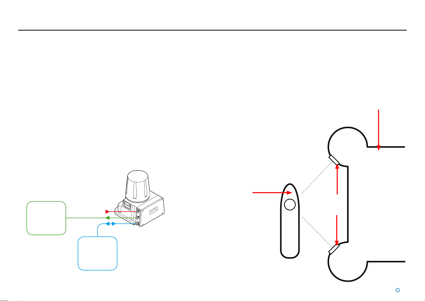
The CyScan System is based on a high accuracy laser sensor and provides positional
information to allow automated approach and/or station keeping relative to a structure or
vessel. It requires one or more reflective targets to be attached to the sides of the structure
or vessel.
The CyScan system is designed to be semi-portable and straightforward to operate. Its
key elements are:
The CyScan Sensor, with integrated Power Supply Unit, which is mounted on the
•
vessel (typically on the wheel-house) as required.
The CyScan Client Software: The CyScan Dashboard is a monitoring and control
•
application running within Microsoft Windows
other computer. This provides the DP operator with status information and control of
the system and the data stream being fed to the DP system. The CyScan Service
Interface is used for system installation and maintenance. This replaces the Service
Access function in earlier versions of the CyScan Dashboard and Console.
The CyScan Targets. Retro-reflectors consisting of high performance reflective
•
tape mounted on a flat or cylindrical support, or – for longer-range capability – prism
clusters.
TM
on a Type 2 Marine Processor or
CyScan
DP
Power
Sensor
System
CyScan emits eye-safe infra-red light and detects the reflections received back from one or
more targets mounted on designated structures or vessels. The range and bearing of the
target(s) are accurately measured, displayed on the Dashboard screen and automatically
transmitted to the vessel's DP system.
CyScan
Vessel
C
CyScan
Targets
Structure
or Vessel
Client
Software
Computer(s)
The key elements of the CyScan system
l
7
Page 8
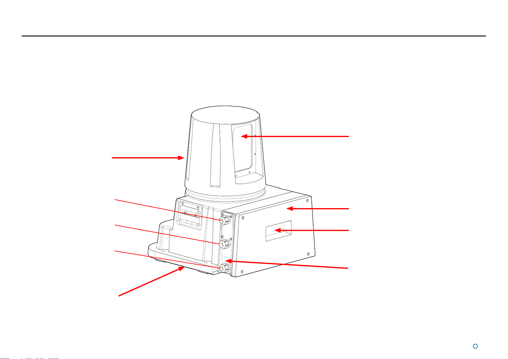
CyScan Sensor Part Names
The diagram below illustrates various parts of the sensor unit and gives the terms used for them.
Rotor
Power
Optical Window
DP Feed
Client Data
Base Plate
Access Plate
Sensor Information
Display
Cable Gland Plate
l
8
Page 9

Getting Started
This section contains the following pages:
Start Up and Shut Down (page 10)
•
Screen Layout (page 11)
•
Tracking Information Quality (page 18)
•
Display Settings (page 19)
•
Vessel Orientation (page 20)
•
You may also find the following sections of the Appendices useful at this stage:
Using the On Screen Keyboard (page 57)
•
Working with Alarms (page 58)
•
l
9
Page 10
Start Up and Shut Down
Start Up
To Start CyScan Dashboard
1. Ensure that the CyScan sensor is powered on.
2. Double-click on the CyScan Dashboard icon.
(Or run the CyScan Dashboard application from
Start > All Programs > Guidance Marine Ltd >
CyScan > CyScan Dashboard).
3. The Dashboard display screen will appear.
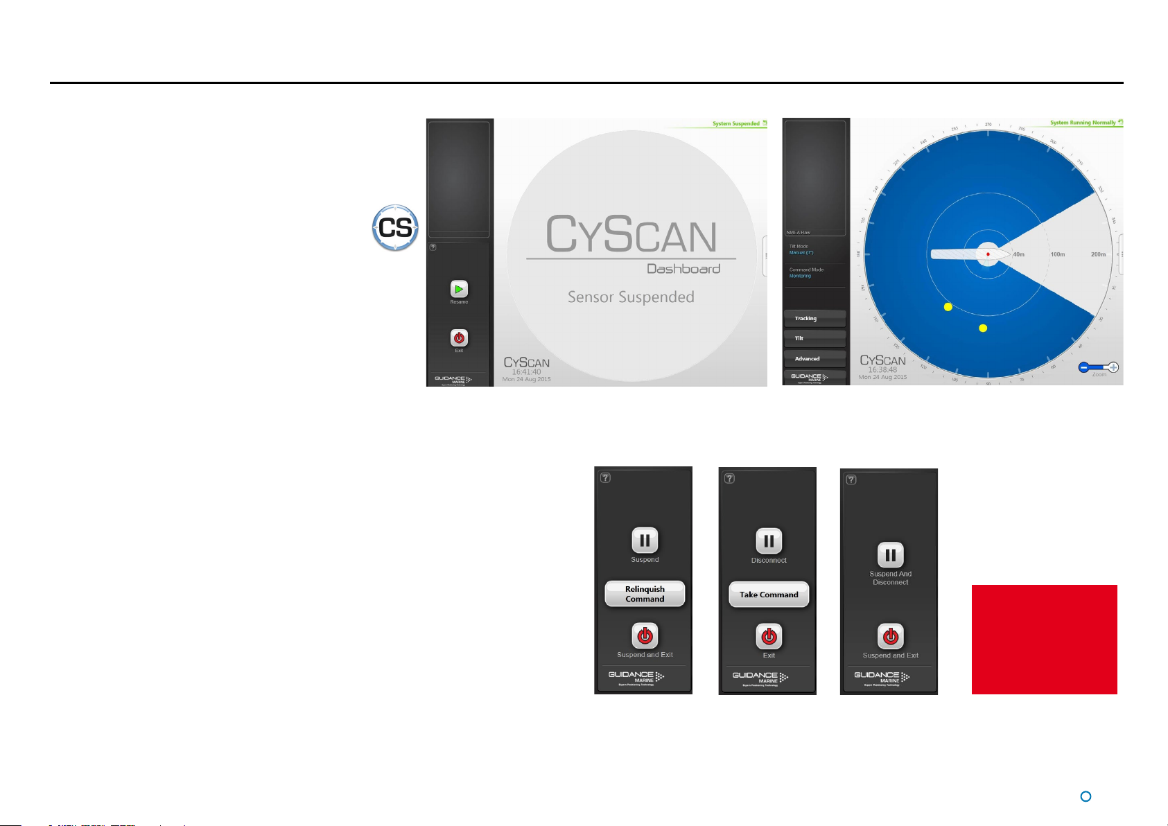
If the sensor is currently suspended, the main part of
the screen will be greyed out. Click on the Resume
button in the side bar in order for the sensor to begin
scanning and for the results to be displayed on the
screen. If the sensor was already scanning, any targets
in view will be displayed straight away.
Shut Down
To Suspend, Exit or Disconnect
1. Click on the Guidance button in the lower left corner of the screen
This will reveal buttons in the side bar as follows: (see right).
Dashboard screen with sensor suspended Dashboard screen with sensor scanning
Suspend - Places the sensor into a ‘sleep mode’. The rotor ceases spinning and the
•
scanner tilt returns to a fixed state. However, upon command from the Dashboard
application, the unit will return to full operation. This mode is suitable for use when
travelling between locations.
Disconnect - Ceases communications between the Dashboard and sensor and
•
causes the main part of the screen to be greyed out. Does not cause the sensor to
stop spinning or tracking targets.
Suspend And Disconnect – A combination of the above two functions (Serial
•
Dashboard only).
Suspend And Exit - Places the sensor into the same ‘sleep mode’ as the suspend
•
command (discussed above) and also closes the CyScan Dashboard program.
Exit - Closes down the Dashboard without affecting the sensor.
•
Dashboard
In Command
Dashboard
Monitoring
Serial
Dashboard
See Multi-Dashboard
(Ethernet) CyScan
Systems (page 41)
for information on In
Command/Monitoring
functionality.
10
l
Page 11
Screen Layout
The CyScan Dashboard screen is
split into three distinct sections,
these are:
1. Main Screen and Bird's
•
Eye View (BEV) (see page
12)
2. Side Bar (see page 14)
•
3. Menu Pane (see page
•
16)
1
2
3
l
11
Page 12
Screen Layout (Continued)
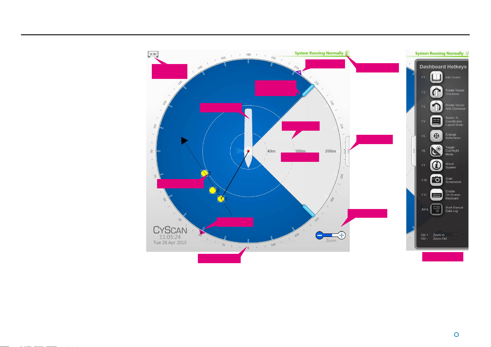
Main Screen and Bird's Eye View (BEV)
The centre of the circular BEV represents
the CyScan sensor and it shows the relative
positions of the CyScan vessel and any detected
reflections.
Vessel Outline
The length and breadth of the vessel and the
offsets and orientation of the CyScan sensor
within it can be configured using the CyScan
Service Interface (see Installer's Guide) so
that the vessel image is correctly scaled and
positioned on the BEV.
Blanking Zone
The Blanking Zone is the sector within each
revolution of the sensor rotor where the laser is
switched off. It is typically set to correspond to
the area in which the beam would strike portions
of the vessel structure. The blanking zone can be
adjusted using the Drag Handles, to suit different
situations (See
Range Circles
The Range Circles act as a visual guide to show
the distance between the CyScan vessel and
the detected reflections. Distances are shown in
metres from the CyScan sensor. Use the Zoom
Control to change the scale of the display. (See
page 13).
Blanking Zones on page 22).
Data Logging
Indicator
Reflection Images
Vessel Outline
Bearing Tag
Radial Markers
Blanking Zone
Drag Handles
Range Circles
Blanking Zone
Heading Tag
Status Display
Hotkeys Tab
Zoom Control
Hotkeys Menu
Radial Markers
These form an angular scale in degrees,
clockwise around the circumference of the BEV.
Zero is defined by the bow of the vessel, or by a
line between the primary and secondary targets,
or by a manual alignment of vessel heading,
depending upon the selected tracking mode, DP
format and display coordinates.
l
12
Page 13

Screen Layout (Continued)
Reflection Images
Reflections received by the sensor are displayed as yellow circles. For tracking you
must select the reflection(s) that correspond to the physical target(s) to be used. During
multi-target tracking, grey boxes are drawn around the selected reflections to indicate a
strong association with the target (i.e. the system is receiving good data and is confident
of the target position). A red box appears around a selected reflection during tracking if the
system has lost sight of the target, or there is insufficient data being received to use it for
tracking.
Bearing and Heading Tags
These are displayed on the Radial Marker when the system is in tracking mode, to indicate
the bearing of the primary (or only) target and the vessel's heading. The visibility of these
two elements depends on the DP format selected and which coordinate system is being
used to display the positional information (see
Data Logging Indicator
This symbol is displayed when data is being logged to disk. During a tracking operation the
symbol is steady and when manual logging is in progress it flashes.
Positional Display Modes on page 29).
Zoom Control
Click on the left-hand side of the control (marked '-') to zoom out of the display and on the
right-hand side ('+') to zoom in.
System Status
This consists of two fields:
Primary
The primary part of the of the Main Screen. It indicates the current status of the system
(e.g. running, suspended or error).
Secondary
The secondary status display is located in the lower right corner of the Main Screen
(beneath the zoom function) and is normally hidden. It displays a flashing message for a
number of seconds in order to confirm an action taken by the user, e.g. starting manual
data logging. It can also display a persistent, static message if there is a communications
problem.
l
13
Page 14
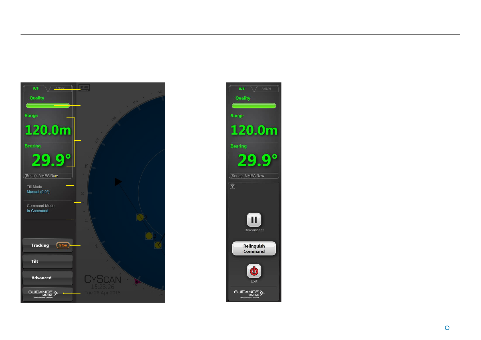
Screen Layout (Continued)
Side Bar
The Side Bar, the black pane to the left of the BEV, contains control and display
components in addition to the coordinates pane.
Toggle Coordinate Type
Signal Quality
Coordinate Data
DP Message Format
After pressing the
Guidance button:
Current Tilt Mode
and Command Mode
Stop Tracking Button
(visible only whilst tracking)
Guidance Button
l
14
Page 15
Screen Layout (Continued)
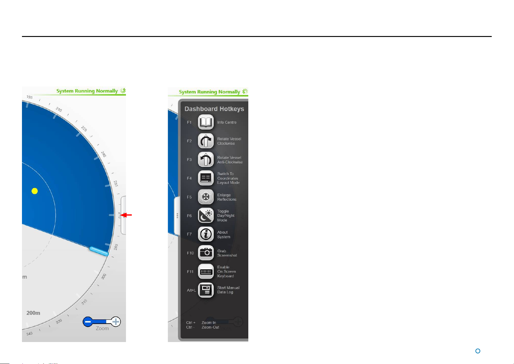
Hotkey Buttons
Selecting the Hotkeys tab on the right-hand side of the main
screen activates the Dashboard Hotkeys menu.
The following keys - and the corresponding buttons on the Dashboard Hotkeys menu - act
as shortcuts to application functions.
F1 Help Menu
F2 Rotates the vessel clockwise
F3 Rotates the vessel counter-clockwise
F4 Toggles between BEV and Coordinates Layout Mode
F5 Toggles between enlarged and standard-sized reflections
F6 Toggles between the day view and night view
F7 Toggles between the About System pane and the full main screen display
F10 Takes a snapshot of the screen and stores the image with the log data
F11 Toggles the on screen keyboard
Hotkeys Tab
Alt+L Start Manual Data Log (available when no tracking operation is in progress): Starts
data logging and changes the button to Stop Manual Data Log
Ctrl + Zoom-In
Ctrl - Zoom-Out
Esc When in operation confirmation mode, cancels the current operation request; in all
other modes, brings back the full BEV screen
Return When in operation confirmation mode, confirm the current operation request
15
l
Page 16
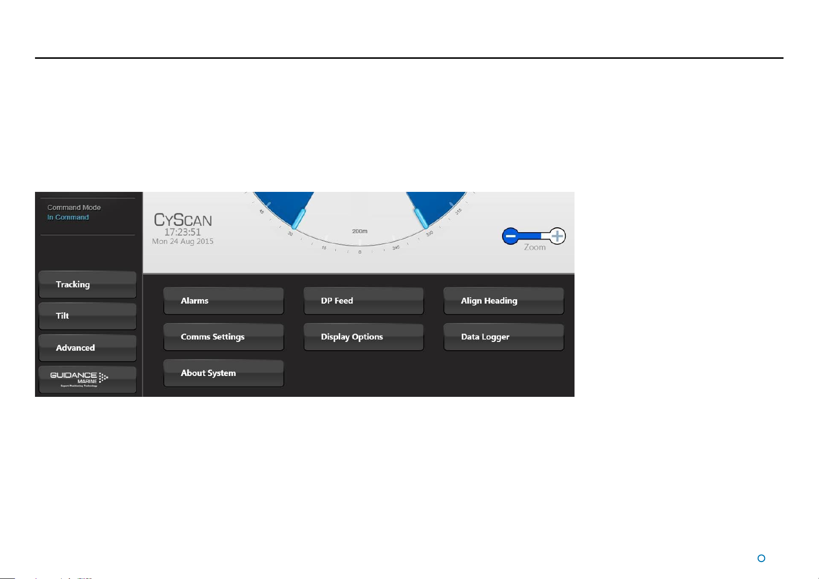
Screen Layout (Continued)
Menu Pane
The Menu Pane, located across the bottom of the CyScan Dashboard Screen, is not always visible. It appears when one of the
Tracking, Tilt or Advanced buttons near the foot of the Side Bar are pressed, which causes the Bird's Eye View (BEV) to contract
towards the top of the screen. Clicking the same button for a second time causes the Menu Pane to disappear and the BEV to be
restored to full size.
The Menu Pane is used to display a wide variety of information and controls, often accessed by further tabs and buttons that
become available once the Menu Pane is in place.
l
16
Page 17
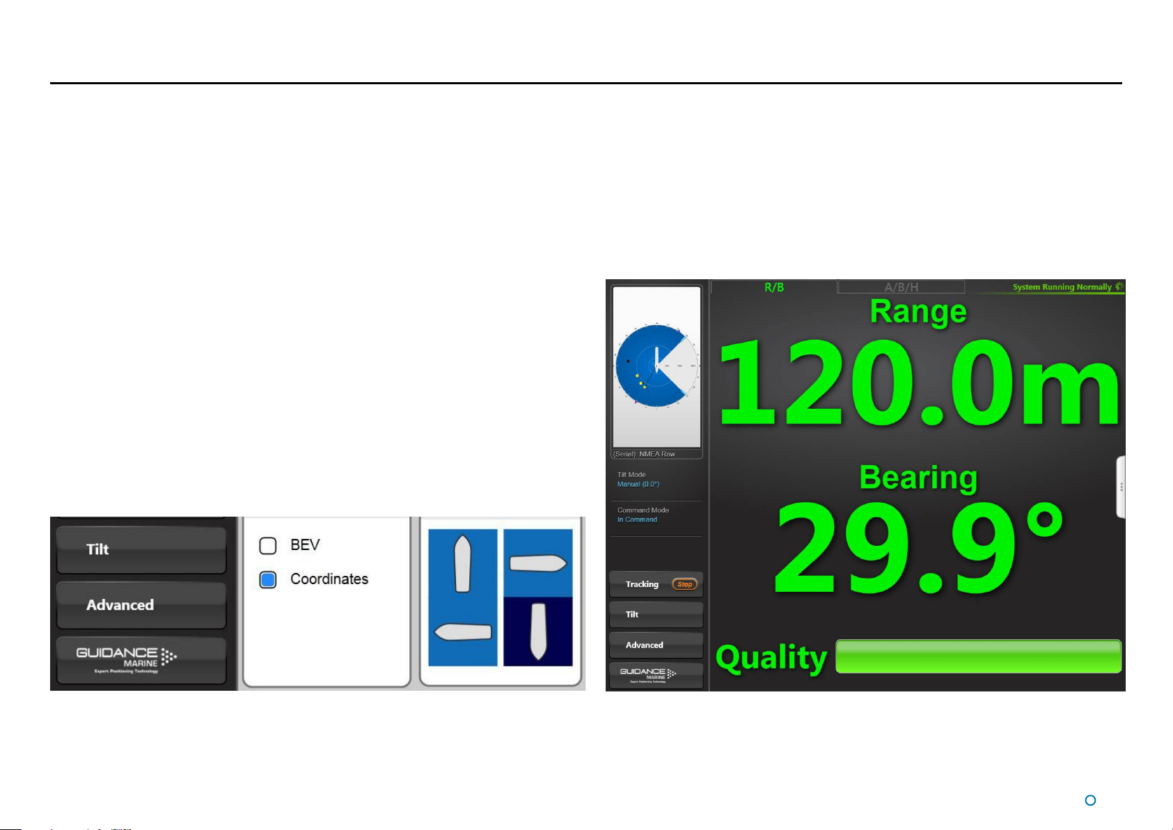
Screen Layout (Continued)
Coordinates View
Whilst tracking is in progress, the positional coordinates and the Bird’s Eye View can be
transposed, so that the coordinates are displayed in extra-large numerals on the main
screen, whilst a miniature BEV is shown at the top of the side bar.
If tracking ends, the layout automatically reverts to Bird’s Eye View, but as long as
Coordinates View remains selected, the main screen will again display coordinates once
the next tracking operation commences.
To Select Coordinates View
This can be done in a number of ways:
1. Navigate to Advanced > Display Options > Screen Layout.
•
2. Click on the Coordinates radio button.
Click on the numerical data near the top-left corner of the screen.
•
Press F4.
•
Click on Switch To Coordinates Layout Mode in the Dashboard Hotkeys menu.
•
l
17
Page 18
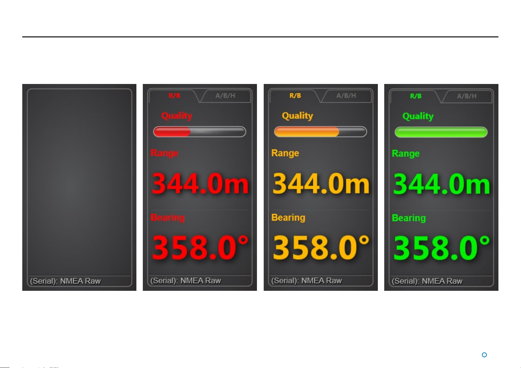
Tracking Information Quality
The CyScan Sensor rotates anti-clockwise. On each rotation, the sensor emits a beam of infrared laser light and analyses the position of any reflections that it receives.
After several rotations, the sensor is able to compare the reflections received on the last rotation with those received during previous rotations. This enables CyScan to recognise the
reflections from the intended targets and to ignore any unwanted reflections.
Before tracking has been selected, the Data Quality and Coordinates area in the upper left corner of the screen is empty. After tracking is started, the coordinates are initially displayed in
red or amber and the quality bar is partially filled with the same colour.
After a few seconds, as the scanner gathers more information, the colour changes from amber to green and more - or all - of the Quality bar is filled. This indicates that the system is
reliably tracking the targets.
18
l
Page 19
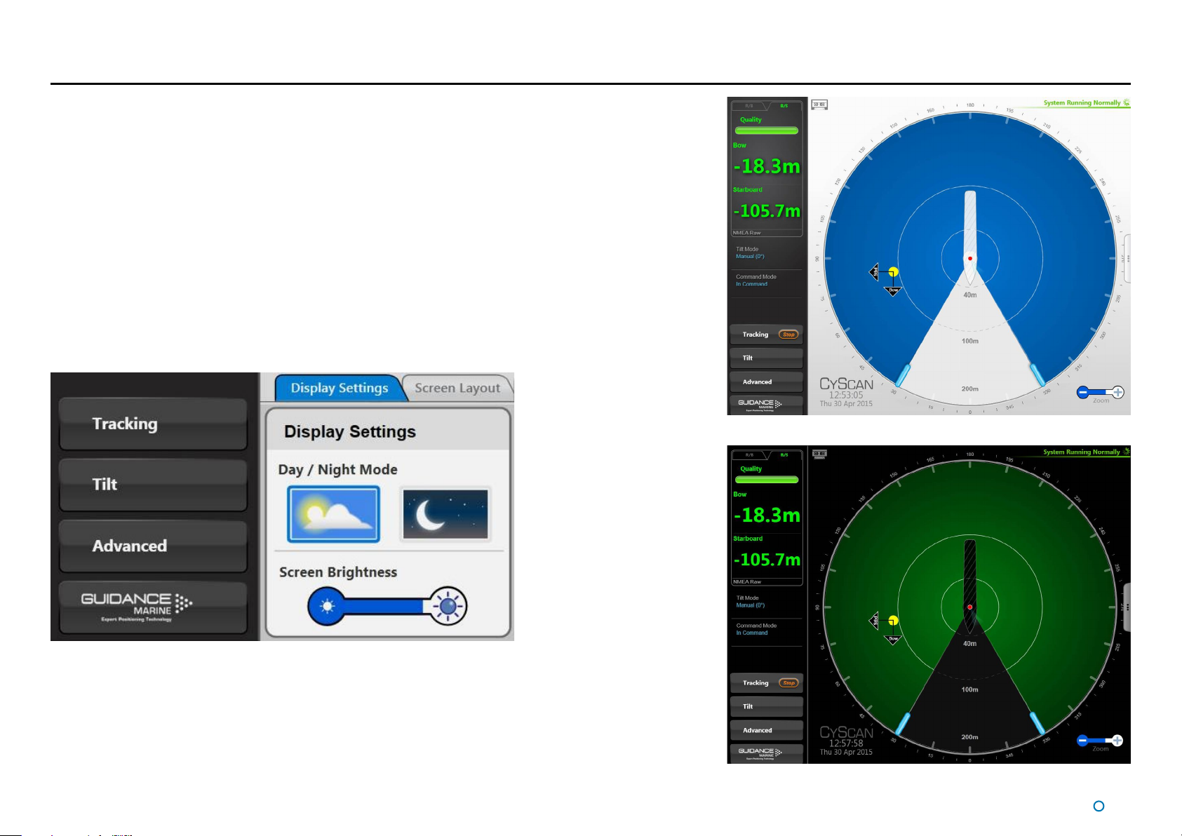
Display Settings
To provide ample visibility during daytime operation and to limit glare during night shifts,
CyScan Dashboard offers two display settings: Day Mode and Night Mode. In either mode
the brightness can be further adjusted by the Screen Brightness control.
To change day/night mode and adjust brightness:
1. Navigate to Advanced > Display Options > Display Settings.
2. Click on one of the Day / Night Mode symbols.
3. Click on the left side of the Screen Brightness control to dim the screen and on the
right to make it brighter.
Alternatively, to toggle between day and night mode, use the keyboard shortcut F6 or the
Toggle Day/Night Mode button in the Dashboard Hotkeys panel.
Day Mode
Night Mode
l
19
Page 20
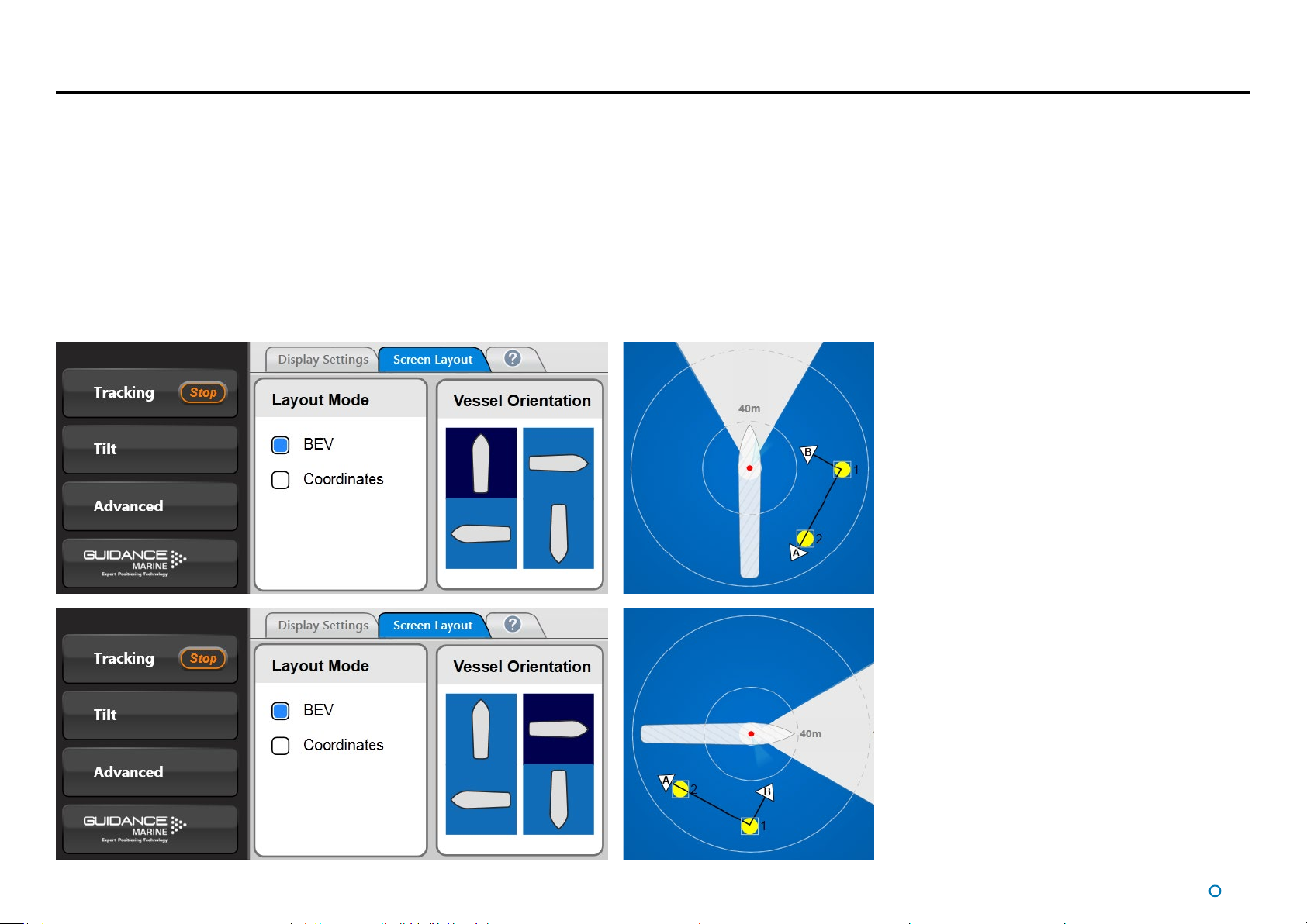
Vessel Orientation
CyScan Dashboard supports four different layouts of the Bird’s Eye View so that the
operator can choose the one which best represents his surroundings.
For instance, if the operator is facing forward when using the Dashboard, he may want the
bow of the vessel in the BEV to point upwards, so that targets located on the starboard
side of the vessel are shown on the right-hand side of the BEV.
To set Vessel Orientation:
1. Navigate to Advanced > Display Opons > Screen Layout.
2. Click on the vessel outline that points in the required direcon.
l
20
Page 21

Tracking Basics
This section contains the following pages:
Blanking Zones (page 22)
•
Working with Reections (page 23)
•
Scanner Tilt Controls (page 25)
•
l
21
Page 22

Blanking Zones
The Blanking Zone is used to mask a segment of the scan rotation. When the scanner
passes through the blanking zone, the laser is switched off to prevent any unwanted
reflections from being mistaken as targets.
N.B. Even if the sensor has a clear 360° view, there must be a blanking zone of at least
23°.
Generally, once the blanking zone has been set, it will not need to be changed. However,
there may be occasions when it is necessary to adjust the blanking zone, for example if the
target is on the opposite side of the vessel to normal.
Setting the Blanking Zone
The start and end of the zone can be set to any positions around the circle to the nearest
degree, subject to the minimum and maximum sizes of the zone.
To define the Blanking Zone
1. Click one of the blanking zone handles and, holding down the left mouse button,
drag to the desired position. Alternatively - on a touchscreen - touch and drag. As
the handle is moved, its current position (in degrees clockwise from the vessel bow) is
displayed in blue numerals outside the perimeter of the circle.
2. If required, drag the second zone handle in the same way.
3. The Apply-Cancel buttons will have popped up after step 1. Click on the Apply button
to set the blanking zone, or on Cancel to restore the blanking zone to its previous
state.
The blanking zone must cover at least 23° but no more than 337°.
l
22
Page 23

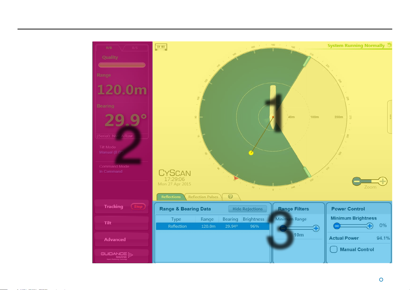
Working with Reflections
Basic Refections Data
Reflections data is displayed on two panes accessed via the Tracking Button. The
Reflections pane contains a list of reflections that are visible to the scanner, and the Range,
Bearing and Brightness level of each:
The user is able to filter out unwanted reflections (see following sections) and can choose
whether to include rejected reflections in the list by means of the Hide Rejections / Show
Rejections toggle button.
a. Filtering by Range
Allows the user to discard reflections that are closer than the threshold range. For example,
setting the range threshold to 35m will cause any reflections from less than 35m away to
be discarded. The range threshold can be adjusted between 5 and 70 metres by clicking
on the end of the filter bar marked '+' or '-' as required. A corresponding grey circle is
shown on the BEV.
b. Filtering by Reflection Brightness
Allows the user to reject reflections that are below the threshold brightness level. For
example, if you set a threshold of 20%, any reflections that have a brightness of 20% or
less will be rejected. The threshold can be adjusted between 0% and 100% (reflection
brightness is measured as a percentage of the brightness of the light emitted by the laser).
Filtering Reflections
The Filter Reflections function on the Reflections pane allows the user to set minimum
range and brightness thresholds. Any reflection at a shorter range than the range threshold
is not included in the list of reflections nor displayed on the BEV. Any reflection with a lower
brightness level than the brightness threshold is classified as a ‘reject’ in the Type column
of the list of reflections and is represented as a red square on the BEV. This mechanism
is useful when unwanted reflections cannot be eliminated by means of the blanking zone
function alone. It can be used at any time, even during tracking.
Range Filter Bar Brightness Filter Bar
l
23
Page 24

Working with Reflections (continued)
Extended Reflection Data
The Reflection Pulses pane contains details about the number of pulses that make up each
reflection, and their angle of incidence.
Pulse - This column displays the number of laser pulses that have been received back
from each target in the following format:
USING/BAD/TOTAL/REJECTED
For example, if the pulses column was displaying 9/1/11/1, it would indicate that CyScan
was using 9 laser pulses for the position calculation, and had discarded 1 bad pulse and
rejected 1 pulse out of a total of 11.
In general, the larger the target the more pulses that will be returned.
This value will increase as the distance to the target reduces.
Width - The Width column shows the horizontal width of each target, measured in
degrees.
Lower, Middle and Upper - These columns indicate whether
the scanner is pointing too low or too high in relation to the detected reflections.
This can occur when the CyScan vessel is working close to a rig and the targets are
mounted high above the scanner (see
Manually Tilting the Scanner on page 26).
Rev # - The total number of revolutions made by the scanner rotor since CyScan was last
powered up or resumed.
Marker - The Marker displays the orientation of the scanner in relation to the vessel:
0° indicates that the scanner has been mounted with its information display facing the
bow. 180° indicates that the scanner has been mounted with its information display facing
the stern.
Pulses - The total number of pulses received during the last revolution of the scanner rotor.
Temperature - The temperature inside the scanner unit (see
Operation on page 56).
Low Temperature
High readings in either the lower or upper channels can also be caused by unwanted
reflections and do not necessarily indicate that the scanner is pointing too low or too
high in relation to the intended target
l
24
Page 25

Scanner Tilt Controls
The scanner tilt mechanism automatically compensates for the pitch and roll of the vessel
caused by wave motion.
Motion sensors and a tilting optics mechanism ensure that the scanning optics remain at
the correct level to see the target.
Scanner Tilt Modes
The scanner can be operated in either of the following tilt modes:
Auto - The scanner tilt automatically adjusts to compensate for draught changes as
•
the vessel loads or unloads, and for gradual tidal movement. Also effective when the
elevation angle of targets increases as the vessel approaches a platform.
Manual - This mode is used to manually tilt the optics to reach the target. For
•
example, when station-keeping close to a platform where the targets are mounted
high up and the CyScan optics must be tilted up at them. (See
Scanner on page 26).
The current tilt mode and leveller angle (if non-zero) are displayed in the ‘Tilt Mode:’ section
of the Side Bar.
To change the scanner tilt mode and leveller angle
1. Click on the Tilt button in the Side Bar.
Manually Tilting the
2. Select the required mode and click on the Apply button to confirm.
3. Click on the +/- buttons to adjust the angle. The adjacent list of estimated elevation
angles for visible targets helps you to arrive at the best leveller angle.
4. Click on the Apply button to confirm your changes.
Sidebar Tilt Mode section
Tilt Mode Selection
l
25
Page 26

Scanner Tilt Controls (Continued)
Manually Tilting the Scanner
The Manual mode is used to tilt the scanner optics to a user-defined angle so that the
centre of the fanned beam is pointing at the target. This may be necessary when the
CyScan Vessel is close to a platform and the targets are positioned above the sensor.
Upper Channel
Middle Channel
Lower Channel
Beam Spread
The CyScan optical receiver is divided into three vertical channels: Lower, Middle and
Upper. The proportion of beam signal being received in each channel is used to determine
the correct angle to set the optics.
If one of the reflections in the list is selected, its elevation relative to the horizontal is shown
by the position of the yellow target symbol on the right-hand side of the Leveller Graphic.
The blue line represents the laser beam, and this moves as the +/- buttons are clicked.
When the laser line points to the centre of the target symbol, this indicates that the leveller
angle is ideal for the selected target
Scanner tilted up and pointing at a target mounted higher than the sensor.
Spirit Level
The Spirit Level control, on the left hand side of the Tilt
pane, displays the roll and pitch of the vessel as measured
by the Vertical Reference Unit within CyScan. The graphical
display represents the roll and pitch angles in the same
manner as a bull’s eye spirit level. The current values are
displayed in text at the bottom of the control. A ship outline
is shown in the background to indicate orientation relative
to the vessel.
l
26
Page 27

Single and Multi-Target Tracking
This section explains the different types of target tracking that can be performed using the
CyScan Dashboard, and how to configure them. It does not provide advice on how to set
up a tracking operation for a specific DP system or application.
The information contained in this section is for general guidance only. This section does
not provide an exhaustive explanation of target tracking using CyScan, nor does it form
the basis of a contract. Implementation of the material covered in this section will vary
according to the type of DP system used in conjunction with the CyScan system. The use
of, or reliance on, anything in this section is therefore entirely at the user’s own risk and
should only be undertaken after assessment of its accuracy, completeness and suitability
for the proposed use.
This section contains the following pages:
Introduction to Single and Multi-Target Tracking (page 28)
•
Positional Display Modes (page 29)
•
Selecting Targets for Multi-Target Tracking (page 31)
•
Axis Orientation and Vessel Heading (page 34)
•
Rotational Offsets (page 36)
•
l
27
Page 28

Introduction to Single and Multi-Target Tracking
The CyScan system can track either a single target or multiple targets:
Single-Target Tracking
During Single-Target Tracking, only one target is used.
Single-Target Tracking is quick and easy to use, but has the following limitations:
Tracking stability is affected if the target reflection is temporarily lost,
•
as there is no redundancy.
If the true target reflection is obscured by vessel operations,
•
there is a possibility that the sensor track could jump to another reflection.
Relative vessel heading cannot be calculated.
•
Multi-Target Tracking
In Multi-Target Mode, CyScan uses between two and five targets. Guidance Marine
recommends using a minimum of three targets. Multi-target tracking has the following
advantages compared to single-target tracking:
Improved tracking stability.
•
Increased immunity to false reflections.
•
Redundancy allows tracking to continue even if a target is temporarily lost.
•
The vessel’s heading in relation to the Multi-Target Group can be calculated.
•
To Start Tracking
For Single-Target Mode
1. Click on the required target reflection on the Bird’s Eye View. It changes to the selected
state (with the red dash around the outside and number “1” superimposed).
2. Click on the Apply button to confirm and begin tracking.
For Multi-Target Mode
1. Select a minimum of two and a maximum of five target reflections (see Selecting
Targets for Multi-Target Tracking on page 31). An ordinal number will be
superimposed on each as they are clicked.
2. Click on the Apply button to confirm and begin tracking.
N.B. Once a target has been selected, it can be deselected by clicking on it a second time.
Deselecting a target may lead to the automatic re-ordering of other selected targets.
To Stop Tracking
Whilst tracking is in progress, a Stop button is embedded in the Tracking button on the
Side Bar.
1. Click on the Stop button.
2. Click on the Apply button to confirm.
l
28
Page 29

Positional Display Modes
The relative positions of the CyScan vessel and single or multiple targets can be expressed
either as Range and Bearing values, or as 'x' and 'y' positions on a rectangular coordinate
frame.
Coordinate axes are only displayed if the DP feed format is set to either
NMEA0183P or NMEA0183R.
CyScan can also display Range and Bearing data when using these formats, if required.
DP Mode Tracking Type Coordinate Axes
NMEA0183P (Primary)
NMEA0183R (Raw)
All other DP modes display Range and Bearing data only.
When using a DP message format for which more than one display mode is supported,
select the required mode by clicking the appropriate tab above the Data Quality area:
Single-Target
Bow and Starboard Axes
Multi-Target
Single-Target Bow and Starboard Axes
Multi-Target A and B Axes
Range & Bearing
Range and Bearing mode displays the distance and the bearing of the primary (or only)
target from the sensor. The radial markers around the outside of the BEV are zeroed in line
with the vessel bow and a magenta tag marks the bearing which is the angle of the target
clockwise from the bow.
In the case of multi-target tracking, there is also a heading axis. This always passes
through the primary target and by default it points through the secondary target, although
it can be realigned if required (see
Compass on page 40). A purple tag represents the heading, which is the angle of the
vessel bow clockwise from the heading axis.
Aligning Multi-Target Heading with the Ship’s
l
29
Page 30

Positional Display Modes (Continued)
Bow and Starboard Axes
This mode is available for single-target tracking, and for multi-target tracking where the DP
feed messages are sent in NMEA0183P (primary) format.
In this mode, the position of the sensor vessel is expressed in metres from the target along
Bow (B) and Starboard (S) axes which have their origin at the primary (or only) target. The
B and S coordinate axes are always parallel with the vessel's own axes.
For multi-target tracking, the vessel’s relative heading is based upon a third axis passing
through the primary target. By default, the heading axis is drawn between targets 1 and
2 but can be realigned if required. The radial markers around the outside of the BEV are
zeroed in the same direction as the heading axis. The purple heading tag is aligned with
the vessel bow, at the point on the scale that shows the angle of the bow clockwise from
the heading axis.
Bow and Starboard Axes
A and B Axes (A Pos and B Pos)
This mode is only available for multi-target tracking where the DP feed messages are sent
in NMEA0183R (raw) format.
In this mode, the position of the sensor vessel is expressed in metres from the target
along A and B axes which have their origin at the primary target.
The axes are initially aligned with the multi-target group, with the A axis passing through
the secondary target. The vessel's relative heading is measured clockwise from the A
axis. If required, the axes can be manually realigned to correspond with the DP system or
another sensor's coordinate axes.
The radial markers around the outside of the BEV are zeroed in the same direction as the
A axis, which acts as the heading axis. The purple heading tag is aligned with the vessel
bow, at the point on the scale that shows the angle of the bow clockwise from the A axis.
A and B Axes
l
30
Page 31

Selecting Targets for Multi-Target Tracking
The terminology in this section relates to a DP Message Format of NMEA 0183R (Raw), i.e.
A and B coordinate axes instead of Bow and Starboard.
Selecting Reflections
When you select a reflection as a target, make sure that it corresponds to the actual target
that you wish to track against. You can select up to 5 reflections to form a multi-target
group.
The first reflection that you select (target 1) becomes the primary target, which forms the
origin of the A and B coordinate axes.
The second reflection that you select (target 2) sets the default orientation of the A and
B coordinate axes. If there are more than 2 reflections, select the reflection furthest away
from target 1. (See
A further 3 reflections (targets 3, 4 and 5) can be added to give redundancy to the group if
targets 1 or 2 are temporarily lost or obscured.
If more targets are mounted on the rig, then the superfluous ones should be physically
removed and not just omitted from the multi-target group.
CyScan tracks targets more accurately when multiple targets are spaced
asymmetrically (see right). If the targets are not spaced asymmetrically, it is
better to operate with fewer (i.e. 2) targets.
Target Selection Order on page 32).
Correct Asymmetrical Target Spacing
Target 1
Target 3
Vessel
Incorrect Symmetrical Target Spacing
Target 2
Target
Reflective
Surface
Key
Target 1
Target 3
Target 2
Vessel
31
l
Page 32

Selecting Targets for Multi-Target Tracking (Continued)
Target Selection Order
e
Any additional targets (targets
3-5) should be spaced
asymmetrically between the
primary and secondary targets
q
The first target selected
(the primary) becomes the
origin of the coordinate axes.
The targets are numbered
anti-clockwise from the
primary. So the secondary
could be numbered 3 or 4
instead of 2.
Axis B is always 90°
clockwise to Axis A.
w
The second target
selected (the secondary)
sets the default direction
of the A axis.
Axis A runs from
the primary target
to the secondary.
l
32
Page 33

Selecting Targets for Multi-Target Tracking (Continued)
Target Selection Order and Coordinate Axes Direction
The A and B coordinate axes point in different directions according to the order in which
targets 1 and 2 are selected.
By default, axis A runs from target 1 to target 2, and axis B is always drawn 90° clockwise
from axis A.
B
Target 1 Target 2
B
Target 1 on Left
Axis A runs from left to right.
•
Axis B points towards the CyScan vessel.
•
The left-most reflection is selected as target 1 and the
right-most reflection as target 2.
Axis A runs from left to right on the display.
Axis B is drawn 90° clockwise from axis A, and points
towards the CyScan vessel on the display.
Vessel
A
Target
Reflective
Surface
A
Target 2
Vessel
Target 1 on Right
Axis A runs from right to left.
•
Axis B points away from the CyScan vessel.
•
The right-most reflection is selected as target 1 and the
left-most reflection as target 2.
Axis A runs from right to left on the display.
Axis B is drawn 90° clockwise from axis A, and points
away from the CyScan vessel on the display.
Target 1
Key
l
33
Page 34

Axis Orientation and Vessel Heading
Target Orientation in Respect to Axis A
The orientation of the reflective surface of the targets is measured clockwise from the origin
of the A axis to the perpendicular of a line passing through targets 1 and 2.
The default orientation value depends on the relative positions of the targets:
If target 1 is on the left when viewed from the CyScan vessel,
•
the default target orientation value is 90°.
If target 1 is on the right when viewed from the CyScan vessel,
•
the default target orientation value is 270°.
B
270°
Target 1
A
Target 2
90°
B
Target 1 on Left
Default target orientation in respect to axis A = 90°.
Vessel
Target
Reflective
Surface
Key
A
Target 1Target 2
Vessel
Target 1 on Right
Default target orientation in respect to axis A =270°.
l
34
Page 35

T1
T2
T1
T2
Axis Orientation and Vessel Heading (Continued)
Vessel Heading
Vessel Heading is measured clockwise from the origin of the A axis to the CyScan vessel’s
centre-line. The vessel’s relative heading value depends on the orientation of the coordinate
axes. Changing the orientation of the A axis also changes the vessel’s relative heading.
In the examples below, the vessel’s heading relative to the targets remains constant.
However, the system measures different heading values according to the different
orientation of the A and B coordinate axes.
(The reported ‘A Pos’ and ‘B Pos’ values will also change, as the coordinate axes from
which they are measured have moved.)
B
Target 1
90°
B
Target 1 on Left
Vessel heading 90°.
A
Vessel
Target 2
Target
Reflective
Surface
Key
Target 2
A
Target 1
270°
Vessel
Target 1 on Right
Vessel heading 270°.
l
35
Page 36

Rotational Offsets
Some DP systems and applications may require the A and B coordinate axes to be rotated
to match a different heading. For example, to line-up with the DP System’s own coordinate axes, the axes of another sensor, the vessel’s gyrocompass, or any other heading
value.
When the axis orientation is adjusted manually, both the A and B axes are rotated about
their origin in the centre of target 1.
Vessel heading is measured in a clockwise direction from the A axis, so changing the
orientation of the coordinate axes also changes the vessel’s relative heading value.
The orientation of the A and B coordinate axes can be adjusted by aligning the multi-target
group to a given vessel heading.
(See
Aligning Multi-Target Heading with the Ship’s Compass on page 40).
B
Target 1
(Origin)
A
A
Target 2
Target
Reflective
Surface
B
Vessel
Key
l
36
Page 37

Rotational Offsets (Continued)
Axis Orientation and Vessel Heading Examples
In the following examples, the CyScan vessel’s relative heading to the multi-target group
remains constant, and the coordinate axes are rotated clockwise about their origin (target
1). (See
The orientation of the targets with respect to the A axis is measured clockwise from the
origin of the A axis to the perpendicular of a line passing through targets 1 and 2.
Vessel Heading is measured clockwise from the A axis to the vessel’s centre-line.
Aligning Multi-Target Heading with the Ship’s Compass on page 40).
Target 1
(Origin)
A
90°
B
Vessel
0°
Default position (Target 1 on Left)
Rotational Offset = 0°
•
Target Orientation with respect to axis A = 90°
•
Vessel Heading = 0° (parallel with A axis).
•
Target 2
Target
Reflective
Surface
B
Target 1
(Origin)
A
Target 2
0°
90°
A
Vessel
270°
Coordinate axes rotated 90° clockwise from default position.
Rotational Offset = 90°
•
Target Orientation with respect to axis A = 0°
•
Vessel Heading = 270°
•
Key
l
37
Page 38

Rotational Offsets (Continued)
Axis Orientation and Vessel Heading Examples (Continued)
A
180°
Target 1
(Origin)
B
270°
180°
Vessel
A
Target 2
A
270°
Target 1
(Origin)
180°
90°
Vessel
B
Target 2
Coordinate axes rotated 180° clockwise from default position.
Rotational Offset = 180°
•
Target Orientation with respect to axis A = 270°
•
Vessel Heading = 180° (parallel to A axis)
•
Target
Reflective
Surface
Key
Coordinate axes rotated 270° clockwise from default position.
Rotational Offset = 270°
•
Target Orientation with respect to axis A = 180°
•
Vessel Heading = 90°
•
l
38
Page 39

Rotational Offsets (Continued)
Axis Orientation and A Pos and B Pos Coordinates
Changes to the orientation of the A and B axes affect the A Pos and B Pos coordinates of
the targets and the CyScan Sensor. In the following examples, the vessel’s relative position
to the multi-target group remains constant, but the reported ‘A Pos’ and
‘B Pos’ values change as the coordinate axes are rotated:
Target 1
90°
B
Target/Sensor A Pos B Pos
Target 1 0 0
Target 2 100 0
CyScan Sensor 100 100
Vessel
100
Target 2
A
100
CyScan
Sensor
Target
Target 1
B
-50
86.6
60°
A
136.6
Vessel
Target/Sensor A Pos B Pos
Target 1 0 0
Target 2 86.6 -50
CyScan Sensor 136.6 36.6
Target 2
36.6
CyScan
Sensor
Target Orientation with respect to Axis A = 90°
(default 0° offset)
Reflective
Surface
Key
Target Orientation with respect to Axis A = 60°
(manual 30° offset)
l
39
Page 40

Rotational Offsets (Continued)
Aligning Multi-Target Heading with the Ship’s Compass
If you require CyScan to produce a heading based on geographic North rather than on the
orientation of the primary and secondary targets, follow the instructions below.
These cause the A and B axes and position coordinates to be recalculated accordingly.
The heading and position coordinate data sent to the DP system will change instantly when
you confirm the new alignment.
You must deselect the CyScan sensor at the DP Console BEFORE commencing this operation.
To Align Multi-Target Heading with the Ship’s Compass:
Whilst multi-target tracking is in progress using an NMEA DP message format:
1. Navigate to Advanced > Align Heading.
2. Either key the required heading value into the numerical entry box and click Preview, or else
move the red compass needle to the required position, either by clicking and dragging it or by
repeatedly clicking the small +/- buttons.
3. Click on the Apply button to confirm.
Drag the compass needle to the required heading.
Click on the Apply button.
l
40
Page 41

Multi-Dashboard (Ethernet) CyScan Systems
This section contains the following pages:
CyScan Ethernet Dashboard - Monitoring Mode (page 42)
•
CyScan Ethernet Dashboard - In Command Mode (see page 43)
•
Note that a CyScan system running with Serial communications supports only a single
Dashboard, and whenever this is running and connected to the sensor, it is effectively in
command mode.
l
41
Page 42

CyScan Ethernet Dashboard - Monitoring Mode
CyScan, when configured to run with Ethernet communications, supports multiple
Dashboards running simultaneously on the same system. No more than one of these can
be in Command mode at any given time; the others are in Monitoring mode.
When the Dashboard is running in Monitoring mode, the controls relating to the Dashboard
itself will be active, but those relating to the CyScan sensor will be disabled. A Monitoring
Dashboard displays the same reflections and positional data as the Command Dashboard,
although it is updated at a reduced rate (every 3-4 seconds instead of every second). It
cannot initiate or stop tracking operations, nor alter the power control, reflection filtering
nor tilt settings.
When a Dashboard running with Ethernet is launched, it defaults to Monitoring mode if the
sensor is already spinning.
Examples of inactive controls in Monitoring Mode
To switch a Dashboard from In Command mode to Monitoring mode:
1. Click on the Guidance button.
2. Click on the Relinquish Command button.
l
42
Page 43

CyScan Ethernet Dashboard - In Command Mode
When the CyScan Dashboard is running in Command mode all control functions are
available. Any changes made to the tracking or sensor-related settings at the In Command
Dashboard will be visible on the screens of the Monitoring Dashboards. On the other hand,
display options such as Screen Brightness or Zoom level can be set differently on each
individual Dashboard, whether it is Monitoring or In Command.
When the In Command Dashboard is used to suspend the CyScan sensor, a message
will appear on the screens of the Monitoring Dashboards indicating that the system is
suspended. The same message is displayed if a Dashboard is opened whilst the sensor is
suspended (See
In this state, clicking the Resume button on any Dashboard will automatically put that
Dashboard In Command. Clicking Exit will close that individual Dashboard only.
Whenever the system is running, a Monitoring Dashboard can be promoted to In
Command as shown on the right.
Start Up and Shut Down on page 10).
Examples of controls available only In Command mode
To switch a Dashboard from Monitoring mode to In Command mode:
1. Click the Guidance button.
2. Click on the Take Command button.
If there was already an In
Command Dashboard in the
system this will automatically
switch to Monitoring mode when
a different Dashboard is switched
to In Command mode.
If tracking is in progress, data
logging will cease on the previously
In Command Dashboard and
commence on the new In
Command Dashboard.
l
43
Page 44

Support Information
This section contains the following pages:
Serial Numbers and Software Versions (page 45)
•
DP Feed (page 46)
•
Manual Power Control (page 47)
•
Data Logging (page 48)
•
l
44
Page 45

Serial Numbers and Software Versions
These numbers identify the hardware configuration and product revision and will be
requested by Guidance Marine in the event of an application service or support call to the
company.
Product Label
The Part Number and Serial Number can be found on the product label affixed to each
unit.
Software Version Information
The About System pane provides version information about the Dashboard and the
software components within the CyScan sensor. It also contains the serial number of the
sensor.
To Display the About System Pane
1. Click on the Advanced button.
2. Click on the About System button.
CyScan sensor
part number
CyScan sensor
serial number
l
45
Page 46
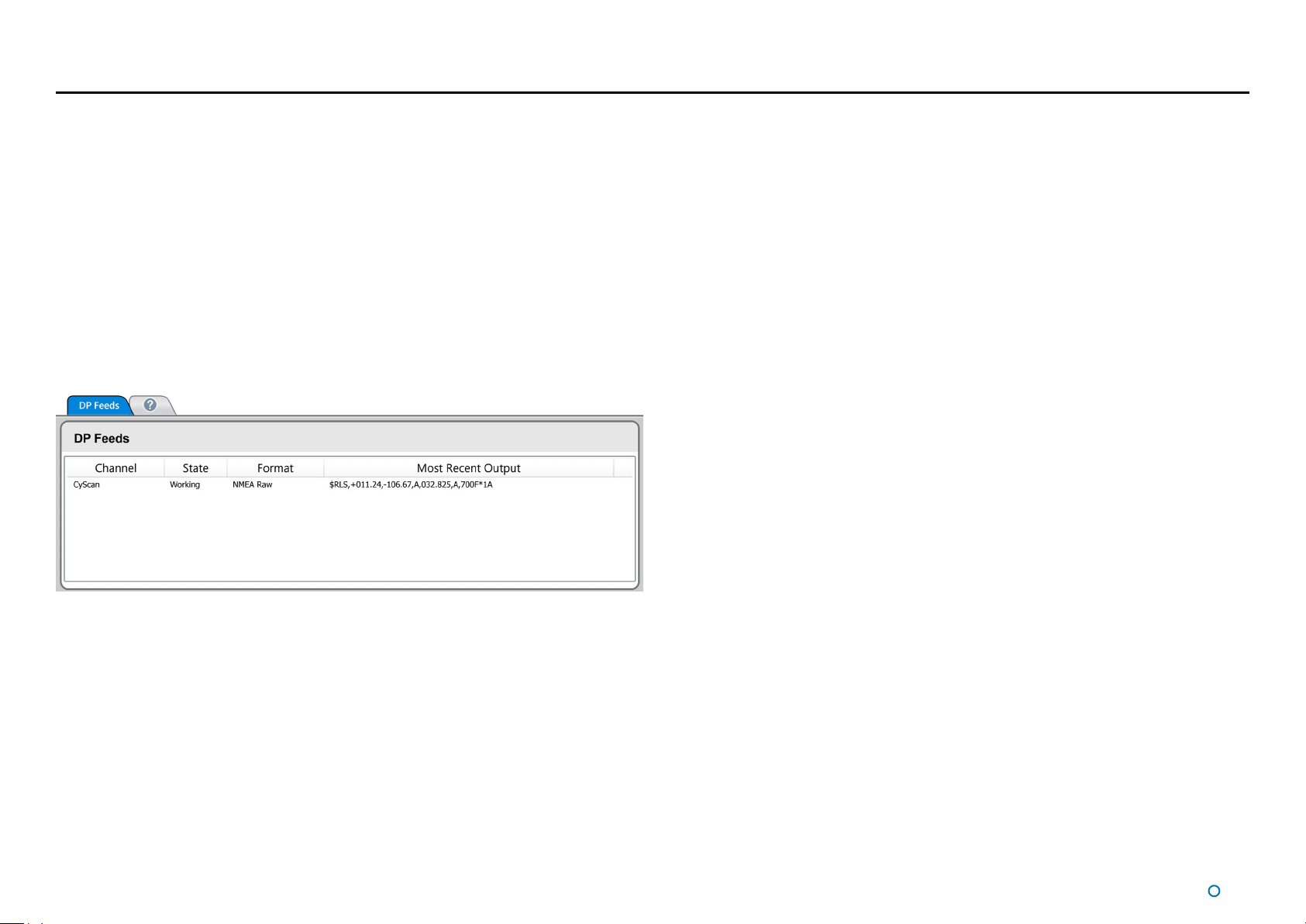
DP Feed
The DP Feed is the data that CyScan transmits to the vessel’s Dynamic Positioning
system. CyScan supports several different data message formats and it is important that
CyScan and the DP system are both configured to use matching formats. However, this
cannot be done from the Dashboard; in order to change the CyScan DP settings, use the
CyScan Service Interface (see document 94-0363-4 CyScan Installer's Guide, which
also contains descriptions of the available DP message formats).
The state of the sensor’s DP output channel, the message format used and the most
recent data output can be viewed on the Dashboard.
To View DP Feed Details:
1. Click on the Advanced button on the side bar.
2. Click on the DP Feed button on the menu pane.
l
46
Page 47

Manual Power Control
Manual Power Control can be used to switch off the normal automatic power control for
the rotor on the CyScan Sensor and to apply and adjust a fixed constant power instead.
To Enable Manual Power Control:
1. Click on the Tracking button on the side bar.
2. Click on the Reflections tab, if not already in focus.
3. Click on the Manual Control tick box, in the Power Control panel.
To Use Manual Power Control:
1. Adjust the power level by clicking on the left or right hand side of the control until the
required value is displayed.
2. Click on the Apply button to confirm the changes.
To Disable Manual Power Control:
Click on the Manual Control tick box and on the Apply button to confirm.
The tick box will clear and the Power Level control will be removed.
l
47
Page 48

Data Logging
During tracking, the system automatically generates a set of operation logs that can be
analysed by a service engineer to diagnose any system faults. Logging can also be started
manually, when the system is not tracking (see below).
Logs can be e-mailed to Guidance Marine Limited (customerservices@guidance.
eu.com) or your DP Supplier in the event of a problem.
On a CyScan system with multiple Dashboards, data logs are written by whichever
Dashboard is in command. If another Dashboard then takes command, the location of
the logs from that time forward will also change.
Starting and Stopping Manual Logging
Any of the following methods can be used to start logging when the system is not tracking
targets:
1. Navigate to Advanced > Data Logger.
•
2. Click on the Start Manual Logging button.
1. Click on the Hotkeys tab.
•
2. Click on Start Manual Data Log.
Press the Alt+L keys.
•
Alternative ways to stop manual logging:
1. Navigate to Advanced > Data Logger.
•
2. Click on the Stop Manual Logging button.
1. Click on the Hotkeys tab.
•
2. Click on Stop Manual Data Log.
Press the Alt+L keys.
•
Click on the Data Logging Indicator in the top-left corner of the main screen:
•
Exporting Data Logs
The most recent data logs can
be exported to a removable
drive on the Dashboard
computer.
To Export Data Logs
1. Insert a USB or other
removable drive into the
Dashboard computer.
2. Navigate to Advanced > Data Logger.
3. Select the period for which you wish to export logs (Last Hour, Last 4 Hours, etc).
4. Select destination drive from the drop-down list, if not already displayed (click on the
Refresh button to refresh the list of available USB drives).
5. Click on Export Data Logs.
Either before or during the export operation, the Refresh button can be used to update the
Available Space field.
Taking Screenshots
The Screenshot option records every detail of
the current screen and stores it as a bitmap
image. Screenshots can be analysed by a
service engineer or e-mailed to Guidance Marine
Limited in the same way as log files.
Screenshots are stored with the data logs and
are included when data logs are exported.
To Take a Screenshot:
There are two alternative ways:
1. Click on the Hotkeys tab.
•
2. Click on Grab Screenshot.
Press the F10 key.
•
The Grab Screenshot and Start
Manual Data Log buttons
l
48
Page 49

Troubleshooting
If you experience problems when installing or using the CyScan system, please check
through this Troubleshooting section for a possible solution. It contains the following pages:
Problems and Possible Remedies (page 50)
•
Cleaning the Sensor and Targets (page 51)
•
CyScan Fuse Information (page 52)
•
If your problem is not listed or you cannot resolve the issue, please contact the system
installer or equipment provider who are trained to assist with installation and operational
problems.
If the problem cannot be resolved by the system installer or equipment provider, please
contact Guidance Marine Limited:
Contact Details
Phone: +44 (0)116 229 2665
•
E-mail: customerservices@guidance.eu.com
•
l
49
Page 50

Problems and Possible Remedies
No communication between CyScan Dashboard and the Sensor
The Dashboard screen turns grey, the Primary Status Display reads “System ERROR”
•
and the Secondary reads “Comms timed out”. Click the Connect button.
Check the power and client connections to the sensor.
•
Check that the unit is displaying either ‘Running’ or ‘Suspended’ alongside the current
•
time on the sensor information display. If it is showing any errors then power cycle the
sensor.
Check that the data feed converter is powered (yellow LED on) and that the outer
•
transmit/receive lights are flashing once every couple of seconds (i.e. the Dashboard is
trying to establish communications with the sensor unit). Under normal conditions the
outer LEDs should flash first followed by the inner two LEDs flashing in response (the
sensor unit answering with data).
Rotor does not rotate
Check the temperature of the unit is above -15 degrees C. Below this the rotor is
•
prevented from spinning to protect the sensor mechanics.
Check that the Dashboard is not showing a ‘Motor Stall’ alarm, if so suspend and then
•
resume the unit to restart the motor.
The sensor rotor might be prevented from rotating due to mechanical
•
blockage. Investigate and remove blockage.
Check the sensor information display on the system unit. Ensure that there are no
•
errors displayed. Otherwise power cycle the unit and observe the messages on the
display.
Check for ice build up under the rotor. Remove any ice which may be present.
•
System appears to be operational but no reflections are displayed
within CyScan Dashboard
Check that the blanking zone is configured correctly.
•
Clean the CyScan sensor window. (See Cleaning the Sensor and Targets on
•
page 51).
Check whether there are any reflections listed on the Reflections menu and that
•
the Zoom control on the main screen is set appropriately.
Check that the Tilt controls are set appropriately.
•
Check that the Power controls on the Reflections menu are set appropriately.
•
System is operational but is not tracking
Check that the sensor has a clear view of the targets.
•
Check that the blanking zone is not blocking targets from view.
•
In the case of Multi-Target tracking, check that a suitable set of targets has been
•
selected (see
System tracking but no data is received at the DP system
Check the DP Feed connection from the sensor.
•
Check that the DP Message Format matches the configuration of the vessel’s DP
•
system.
System operates correctly but in cold weather loses targets.
Check for condensation or ice on targets. Clean if necessary.
•
Check for condensation or ice on the window of the sensor. Clean if necessary.
•
Selecting Targets for Multi-Target Tracking on page 31).
l
50
Page 51

Cleaning the Sensor and Targets
To maintain the CyScan Sensor in good working order it is important that its optical
elements are kept free of contamination.
To clean the optical window
Use a lint-free cloth with IPA spray to carefully wipe the optical window.
To clean the targets
In dirty environments the reflective faces of the targets should be cleaned regularly for best
viewing.
Under icy or frosty conditions, the targets should be cleared of any condensation or ice.
l
51
Page 52

CyScan Fuse Information
The CyScan system contains two replaceable fuses, one for the Live and the other for the
Neutral. These are located on the connector board as shown below.
Connector Board Fuse
Please refer to the Installer’s Guide for details on how
to access the connector board.
To remove a fuse from its housing, fit a flat-head screwdriver into
the slot in the insert - then push it in and turn it anti-clockwise until
the insert releases and can be pulled out.
Reverse the above procedure to replace the fuse.
Both fuses have the same specification.
Ensure the replacement fuse has the same specification as the
original fuse.
Fuse specification:
20mm
T 630mA L 250v
Antisurge Glass
Live
Neutral
CAUTION: DOUBLE POLE/NEUTRAL FUSING
l
52
Page 53

Additional Information
This section contains the following pages:
Targets-Installation and Position (page 54)
•
Low Temperature Operation (page 56)
•
Using the On Screen Keyboard (page 57)
•
Working with Alarms (page 58)
•
CyScan System Specications (page 61)
•
Index (page 62)
•
Document History (page 64)
•
l
53
Page 54

Targets-Installation and Position
CyScan can operate successfully with flat, cylindrical or prism targets. These can be
bought online from www.marine.direct.
Flat Targets
Flat targets are generally attached to rigid structures
such as metal stanchions using steel bands.
2 metre tall flat targets can typically be seen at up to
400 metres in ideal conditions. Shorter 1 metre tall flat
targets are visible at up to 250 metres when viewed
straight on.
Part number: 20-0031-0
(2m x 350mm flat reflector including stainless steel
bands)
Cylindrical Targets
Cylindrical targets can be used up to
approximately 300 metres. They can be hung
over the side of the structure/vessel and secured
at either end.
Part number: 20-0078-0-B
(1.9m cylindrical reflector)
Prism Targets
Prism clusters with multiple 6cm elements
for extended range operations. Variable
configurations allow for optimisation of the
visible reflection, visible reflection level or
reflected power. A fixed layout rugged version
includes a robust housing, brightly-coloured
for easy identification.
Part number: (see www.marine.direct)
l
54
Page 55

45
o
45
o
VIEWABLE
ANGLE
VIEWABLE
ANGLE
0
Targets-Installation and Position (Continued)
Target Installation
Key to the operation of the CyScan system is the correct installation of targets. Please follow
the guidelines given below when installing targets on the structure/vessel.
Once the targets are installed, their relative positions can be automatically surveyed by the
system.
Installation Tips
Targets should be placed in positions where the sensor can see them while the vessel
•
is within the expected working area. Consider vertical position as well as horizontal.
Flat targets should not be placed too far along the structure/vessel from the expected
•
working area as this can reduce the viewing angle for close operations.
The sensor beam should not strike a flat target at an angle of more than 45 degrees to
•
the target surface.
Cylindrical targets can be viewed from any angle equally well.
•
Optimum Spacing for Multiple Targets
Targets should be positioned with unequal spacing between them – this helps the
•
system to distinguish between specific targets. For example, with a typical mooring
distance of 40-80m using three targets, suitable spacings between the targets would
be 10m and 20m – giving a total spread of 30m.
Targets should be placed no closer than 5m together. Ideally they should be placed
•
10m or more apart.
Targets are asymmetrically spaced,
thus making it easier for the CyScan
system to assess which reflection
corresponds to a particular target.
Targets are too close together and
have even spacings. This makes it
more difficult for the CyScan system to
differentiate them.
l
55
Page 56

Low Temperature Operation
Introduction
The CyScan sensor is a precision electromechanical device with hardware components
that, of necessity, are mounted in an external position on a vessel’s superstructure. It is
recognised that industrial marine operations may subject these components to harsh
environments, including low temperature.
The CyScan hardware complies with the requirements of IEC 60068-2-1 and is able to
operate for prolonged periods at temperatures down to – 25°C provided that certain
operating conditions are maintained.
If there is a requirement for CyScan to operate at temperatures below -25°C, contact
Guidance Marine.
Operating Conditions
The following recommendations are made for low temperature use:
If it is necessary for the system to be switched on after a prolonged period at
•
temperatures below 5°C (and down to – 25°C) the sensor will warm itself, but will
require some time to reach optimum operating condition.
If the unit is switched on after a period at temperatures between -15 to -25°C it will
•
not communicate with the Dashboard and the rotor will not rotate until the internal
temperature of the base unit rises above -15°C.
When the system is not in use (i.e. un-powered or suspended) the sensor should
•
be protected by means of a suitable insulating and protective cover to prevent the
external build-up of ice.
For operation below – 25°C additional forced air heating must
be provided. Do not use exhaust emissions as these contain
particulates which will degrade the optics.
Technical Considerations
The CyScan sensor uses a sophisticated rotating infra-red laser range-finder to
•
accurately measure the distance and bearing to retro-reflective targets that are placed
at specific locations in the working area. Movement sensors allow mechanically driven
optics to compensate for vessel motion due to wave action. The internal mechanism
may become disabled if it is allowed to cool in a low temperature environment.
A safety interlock prevents activation of the range-finder laser if the scanner rotor head
•
stops or is prevented from rotating by ice build-up.
View of the retro-reflective targets will be obscured by a build-up of ice on either the
•
optical window of the scanner or the surface of the targets (N.B. ice has poor reflective
properties at the infra-red frequency used by CyScan).
l
56
Page 57

Using the On Screen Keyboard
In order to accommodate systems without keyboards, CyScan Dashboard provides an
onscreen Keyboard (OSK) option. This enables text to be input using only a mouse pointer
or touch screen.
To enable the on-screen keyboard
If, during installation, you indicated that the Dashboard would be used with a touch screen,
the OSK will already be enabled.
Otherwise, click F11 or the Enable On Screen Keyboard button in the Dashboard
Hotkeys menu.
To use the on-screen keyboard
Simply click on any text entry field and the OSK will pop-up ready for use:
In the case of a numerical field, the OSK is restricted to the appropriate keys:
When you have finished using the OSK, proceed to the next relevant action (e.g. clicking
on the Apply button), or else click on a different part of the screen, and the OSK will
disappear.
Click on the necessary keys on the on-screen keyboard using your mouse or by tapping
the touch screen.
l
57
Page 58

Working with Alarms
During operation, the CyScan system produces an audit trail of event messages. These
range in increasing order of severity from: Information, Warning, and Error to Fatal. As
these alarms are raised, the Dashboard lists them within the Alarms pane.
Click on any alarm to display details about it in the right-hand section of the Alarm pane:
The severity and current state of an alarm are reflected in its colour and shape:
Information—grey symbols
•
Warning—orange symbols
•
Error—red symbols
•
Fatal—red symbols
•
The arrowhead symbol indicates that an alarm condition is persisting; an alarm in this state
will show a Start time but not a Stop time.
The square symbol means that the alarm condition no longer exists, therefore the alarm will
show both Start and Stop times.
The pause symbol indicates an instantaneous alarm. In this case, the Start and Stop times
are identical.
When an Error or Fatal alarm is raised, the Alarms pane is opened automatically and the
Advanced button in the side bar is shaded red as in the example above. If the pane is
closed, the Advanced button returns to its normal grey shading.
Additionally, after a Fatal alarm has been raised, close the Dashboard, power down the
sensor and restart the system.
Filtering Alarms
A filter is available to suppress the display of particular alarm types. By default, the filter is
activated and causes information messages to be hidden.
Click on the Alarm Filter button to toggle between activated
Click on the Filter Selection button to choose which types of alarm are to be filtered out:
Alarm types that are ticked are always displayed in the alarms list, un-ticked types are
hidden when the filter is activated.
and de-activated .
l
58
Page 59

Using the Current and Historic Alarms Lists
Using the Historic Alarm List
The Alarms tab has two alarms lists:
The Current Alarms List displays new alarms (since the last start of the Dashboard
•
software).
The Historic Alarms List is used to store alarms that have been cleared from the
•
current list.
Current alarms are automatically transferred when the Dashboard is closed.
Items in the Current List cannot be deleted, they may only be moved to the Historic List.
Only items in the Historic List can be permanently deleted.
To accept alarms in the current list
1. Navigate to Advanced > Alarms and ensure that the Current Alarms tab is in focus.
2. Select the alarms that you wish to move into the Historic list:
To accept one alarm—Click on the required entry and click on the
To accept all alarms—Click on the
Note: This will not apply to alarms that have been hidden by the filter mechanism.
button and click Apply to confirm.
button.
To clear the historic list
1. Navigate to Advanced > Alarms and ensure that the Historic Alarms tab is in focus.
2. Select the alarms to delete:
To delete one alarm – click on the alarm entry and then on the
To delete all alarms – click on the
Note: This will not apply to alarms that have been hidden by the filter mechanism.
button and click Apply to confirm.
button.
To export an alarms list
1. To export all alarms to a text file, click on the Export Historic and Current Alarms button
2. Enter a path and filename for the file to be written, or leave to default.
3. Click on the Apply button.
l
59
Page 60

Network Communications Settings
The Comms Settings menu pane displays the configuration of communications between
the Dashboard and sensor. In the case of Ethernet comms, the IP address can be modified
at the Dashboard; otherwise these settings should be modified using the CyScan Service
Interface (see document 94-0363-4 CyScan Installer's Guide).
To View the Network Comms Settings:
1. Click on the Advanced button on the sidebar.
2. Click on the Comms Settings button on the menu pane.
To Modify the Dashboard’s Record of the Sensor’s IP Address:
The Dashboard first has to be disconnected from the sensor. If already disconnected,
skip to step 5.
1. Click on the Guidance button to reveal the Guidance Home Menu.
2. If the Dashboard is In Command, click on the Relinquish Command button.
3. Click on the Disconnect button.
4. Click on the Guidance button.
5. Navigate to Advanced > Comms Settings.
6. Click on the Edit button.
7. Modify the IP Address field as required.
8. Click on Apply to confirm.
Ethernet Communications Serial Communications
l
60
Page 61

CyScan System Specifications
Sensor
Laser Type Pulsed (min. 30kHz) semiconductor laser diode (904nm)
Laser Classification Eye safe to Class 1 IEC 60825
Beam Shape (nominal) 12° vertical, 0.13° horizontal
Operating Range (nominal) 10m to 3250m (dependent on target size and atmospheric
conditions)
Range Resolution 8.5mm (< 30ps time of flight)
Angular Resolution (typical) 0.012° (0.2 mrad)
Range Repeatability (typical)
Angular Repeatability (typical)
Target to Target Repeat (typical)
Position Repeatability (typical)
Heading Repeatability (typical)
Rotational Scanning Frequency 1Hz (60 rpm), or 2Hz (120rpm) - operator selectable
Levelling Opcs
Active Axis Single axis with automatic dynamic stepper control
Tilt Compensation -20° to +20° roll and pitch (combined)
Sensors 3 axis solid state gyros and accelerometers,
Total Vertical Angular Coverage 52° (mechanical + optical)
Wave Motion Compensation
(typical)
Environmental
Temperature Range Min: -25°C Max†: 70°C
Marine Certification IEC 60945 (IE10) and IMO Resolution A.962(23) 'GREEN
Marine Type Approval ABS, Lloyds Register, DNV, RMRS
EMC Certification CE Certified, FCC Part 15(a)
Compass Safe Distance 1000mm (worst case) @ 0.3° deflection
Water / Dust Protection IP66 rated
75mm [3σ @ <100m], 150mm [3σ @ <1000m]
0.02° (0.35 mrad) [3σ @ <100m],
0.04° (0.70 mrad) [3σ @ <1000m]
0.03° (0.45 mrad) [3σ @ <100m]
0.3m [3σ] or better than 0.5% of range @ <100m,
0.05% @ <1000m
0.5° [3σ @ <100m] - two targets
2 axis inclinometer
±5° for 5 second wave period
PASSPORT'
Vessel Interface
Power Requirement 85-264VAC, 45-65Hz, max100W, 1.5A (fuse)
Sensor Control and DP Feed I/O 2 x RS422 + 2 x Ethernet 100Base-T Auto MDI/X
Sensor Cable Connectors Power (J12) - 3 way R/A socket w/strain relief
Serial (J9 & J11) - 8 way socket w/strain relief
Sensor Diagnostics Display 2 lines 20 character VFD (startup messages and runtime status or
diagnostics)
Service Access I/O 1 x USB 2.0 + 1 x Ethernet 100Base-T + VGA
Supported DP Protocols Standard sensor: NMEA0183R, NMEA0183P, ASCII17, MDL
Standard, MDL Multi-Target, Nautronix Standard, Artemis Mk IV,
Kongsberg Standard, MT Custom, Rolls-Royce Custom
KM sensor: ASCII17, Kongsberg Custom, Kongsberg Standard,
MDL Standard, MDL Multi-Target
Supported Operating Modes Serial Client (single) + Serial DP (single)
Ethernet Client (In Command & Monitoring) + Serial DP (single or
dual)
Sensor Dimensions
Enclosure Anodised alloy with powder coating
Dimensions 405 x 407mm footprint, 456mm height
Weight ca. 25kg (without flight case and accessories)
Flight Case
Dimensions 680 x 570 x 780 mm
Weight ca. 61kg (typical accessories)
Targets
See page 54
†
: Internal to sensor
l
61
Page 62

Index
A
A and B Axes 30
Accept Alarms 59
Access Plate 8
Alarms
Accept 59
Clear 59
Export 59
Filtering 58
A Pos 30
Coordinates 39
Auto Draught Follow 25
Axis Orientation 34
Examples 37
B
Base Plate 8
Blanking Zone
Setting 22
Bow and Starboard Axes 30
B Pos 30
Coordinates 39
D
DP Feed 8
E
E-mail 49
Export
Alarms 59
Data Logs 48
F
Filtering Alarms 58
Flat Targets 54
Fuse Information 52
H
Historic Alarm List 59
Horizontal, Tilt Mode 25
L
Labels 45
Low Temperature Operation 56
P
Part Number
CyScan Sensor 45
Part Numbers
Cylindrical Target 54
Flat Target 54
Phone 49
Positional
Information Quality 18
Positional Display Modes 29
Power 8
Prism
Targets 54
Problems and Possible Remedies 50
Product Labels 45
R
Range & Bearing 29
Rotational Offsets 36
Rotor 8
C
Cleaning 51
Clear Alarms 59
Contact Details 49
Guidance Marine 49
Coordinate Axes Direction 33
Cylindrical Targets 54
CyScan Sensor Part Names 8
M
Manually Tilting the Scanner 26
Manual Power Control 47
Multiple Target Spacing 55
Multi-Target Tracking 27
O
Operating
Conditions 56
Optical Window 8
l
62
Page 63

Index (continued)
S
Scanner Tilt
Controls 25
Selecting Reections 31
Selecting Targets 31
Sensor Part Names 8
Serial Number
CyScan Sensor 45
Single-target navigation 27
Slave 42
Software Versions 45
Spacing Multiple Targets 55
Starboard Axes 30
Sub-zero Temperatures 56
System Logging 48
T
Target
Cylindrical 54
Flat 54
Installation 54
Installation Tips 55
Position 54
Prism 54
Spacing 55
Types 54
Target Spacing 31
Temperature 56
Tilt
Controls 25
Mode 25
Tracking
multi-target 27
single-target 27
, 55
U
Using the Historic Alarm List 59
V
Vessel Heading 34, 35
Examples 37
l
63
Page 64

Document History
Document Number Changes Issue Date
94-0353-4-A First release of CyScan (Dashboard) Operator's Guide 15/10/2013
94-0353-4-B Updated for CyScan v4.83 31/03/2014
94-0353-4-C Inclusion of the Marine brand and the 3 year warranty 31/05/2014
94-0353-4-D Removal of Service Access functionality and other changes for CyScan v4.9
28/08/2015
l
64
Page 65

 Loading...