

GUIDANCE MARINE 20- Series, CyScan AS Installer's Manual
CyScan AS Installer’s Guide
W
A
R
R
A
N
T
Y
S
e
e
o
u
r
s
t
a
n
d
a
r
d
t
e
r
m
s
o
f
s
a
l
e
Q
U
A
L
I
T
Y
A
S
S
U
R
E
D
3
YEAR
Guidance Marine Ltd, 5 Tiber Way, Meridian Business Park, Leicester, LE19 1QP, UK
T: +44116 229 2600 E: sales@guidance.eu.com
featuring CyScan AS
reector detection
www.guidance.eu.com
www.marine.direct
CyScan AS Installer’s Guide
LASER
1M
Print Colour
Black
Print Colour
Yellow
100.00 mm
Scale 1:1
Material
White
Issue Date: 22/02/2018
Document No: 94-0559-B
Serial No:
Sensor Software Version: Client Software Version:
Date of Shipment from UK:
Guidance Marine Ltd,
5 Tiber Way
Meridian Business Park
Leicester
LE19 1QP
UK
Tel: +44 116 229 2600
UK Support: +44 116 229 2665
(365 days a year, 08:00 - 20:00 hours UTC)
customerservices.uk@guidance.eu.com
USA Support: +1 504 305-1120
customerservices.us@guidance.eu.com
Asia Support: +65 6734 6365
customerservices.sg@guidance.eu.com
Web: www.guidance.eu.com/customer-support
Class 1M Laser Product
Complies with EN 60825-1
Complies with USA CFR 1040.10 & 1040.11
except for deviations pursuant to Laser Notice
No 50 26 Jul 2001
Copyright © Guidance Marine Limited. All Rights Reserved.
Copyright in the whole and every part of this document belongs to Guidance Marine
Limited (the “Owner”) and may not be used, sold, transferred, copied or reproduced in
whole or in part in any manner or form or in or on any media to any person other than
in accordance with the terms of the Owner’s Agreement or otherwise without the prior
written consent of the Owner. “CyScan” is a registered trademark of Guidance Marine
Ltd. All other brand or product names are trademarks or registered trademarks of their
respective companies or organisations.
l
2

Table of Contents
Introduction ......................................................................................................5
Welcome �����������������������������������������������������������������������������������������������������������������������6
System Overview ����������������������������������������������������������������������������������������������������������7
What is Absolute Signature (AS)�����������������������������������������������������������������������������������8
CyScan Sensor Part Names ����������������������������������������������������������������������������������������� 9
Serial Numbers & Software Versions �������������������������������������������������������������������������� 11
Product Label �������������������������������������������������������������������������������������������������������������������������������������� 11
Software Version Information ��������������������������������������������������������������������������������������������������������������11
Installing the Sensor Hardware ............................................................... 12
Where to Mount the Sensor ���������������������������������������������������������������������������������������13
Sensor Dimensions and Mounting Template ��������������������������������������������������������������14
Installing the Cables .................................................................................... 15
Cable Specifications ��������������������������������������������������������������������������������������������������16
UPS Specifications ����������������������������������������������������������������������������������������������������� 17
Legacy CyScan Sensor Connections ������������������������������������������������������������������������� 18
To Connect a Cable to the CyScan Sensor ����������������������������������������������������������������������������������������� 18
Connecting the Power Cable ��������������������������������������������������������������������������������������������������������������18
Legacy Client and DP Feed Connections - Ethernet Client, Serial DP ����������������������19
Legacy Client and DP Feed Connections - Ethernet Client, Dual Serial DP �������������� 20
Legacy Client and DP Feed Connections - Serial Client, Serial DP ��������������������������� 21
CyScan AS Sensor Connections �������������������������������������������������������������������������������� 22
To Connect a Cable to the CyScan Sensor ����������������������������������������������������������������������������������������� 22
Connecting the Power Cable ��������������������������������������������������������������������������������������������������������������22
CyScan AS Client and DP Feed Connections - Ethernet Client, Serial DP ����������������23
CyScan AS Client and DP Feed Connections - Ethernet Client, Dual Serial DP �������24
CyScan AS Client and DP Feed Connections - Serial Client, Serial DP ��������������������25
Installing the Control PC ............................................................................ 26
Installing CyScan Client Software onto a Computer �������������������������������������������������� 27
Conguring the CyScan System .............................................................. 28
Using the CyScan Service Interface ��������������������������������������������������������������������������� 29
Network Communication Settings �����������������������������������������������������������������������������30
Vessel Parameters ������������������������������������������������������������������������������������������������������32
Static Blanking Zones ������������������������������������������������������������������������������������������������35
DP Feed Configuration ����������������������������������������������������������������������������������������������� 36
System Parameters ���������������������������������������������������������������������������������������������������� 38
Additional Information ............................................................................... 40
Target Types ���������������������������������������������������������������������������������������������������������������41
Positioning and Mounting Targets ������������������������������������������������������������������������������42
DP Message Types �����������������������������������������������������������������������������������������������������43
NMEA0183R Format ���������������������������������������������������������������������������������������������������������������������������43
NMEA0183P Format ����������������������������������������������������������������������������������������������������������������������������43
ASCII17 Format ����������������������������������������������������������������������������������������������������������������������������������� 44
MDL Standard † ����������������������������������������������������������������������������������������������������������������������������������44
MDL Multi-Target † �����������������������������������������������������������������������������������������������������������������������������44
Nautronix Standard † ��������������������������������������������������������������������������������������������������������������������������44
Artemis Mk IV † �����������������������������������������������������������������������������������������������������������������������������������44
Kongsberg Standard ���������������������������������������������������������������������������������������������������������������������������44
MT Custom DP String �������������������������������������������������������������������������������������������������������������������������45
Rolls-Royce Custom DP String ����������������������������������������������������������������������������������������������������������� 46
Kongsberg (Custom)����������������������������������������������������������������������������������������������������������������������������47
CyScan AS Installation Checklist �������������������������������������������������������������������������������48
Cable Routing Diagrams ��������������������������������������������������������������������������������������������49
Sensor Information Display - Error Messages ������������������������������������������������������������ 54
Upgrading the Sensor Software Via the Remote Installer ������������������������������������������56
Upgrading the Sensor Software Directly ��������������������������������������������������������������������57
Remote Diagnostics ���������������������������������������������������������������������������������������������������58
l
3

Table of Contents (continued)
Index ��������������������������������������������������������������������������������������������������������������������������� 59
Document History ������������������������������������������������������������������������������������������������������61
l
4

Introduction
This section provides an introduction and overview of the CyScan system.
It contains the following sections:
Welcome (page 6)
•
System Overview (page 7)
•
What is Absolute Signature (AS) (page 8)
•
CyScan Sensor Part Names (page 9)
•
Serial Numbers & Software Versions (page 11)
•
l
5
Welcome
Welcome to the CyScan AS Installer’s Guide. It explains how to commission and install the
CyScan system onto a vessel and how to install the CyScan Service Interface (CSI) and
Dashboard. An on-screen version of this document can be opened from the About tab of
the CSI. For Instructions on how to use CyScan, please see the CyScan AS Operator’s
Guide (Doc 94-0560).
Note: Installation of a CyScan system should be carried
!
out by a suitably qualified and competent engineer.
l
6
System Overview
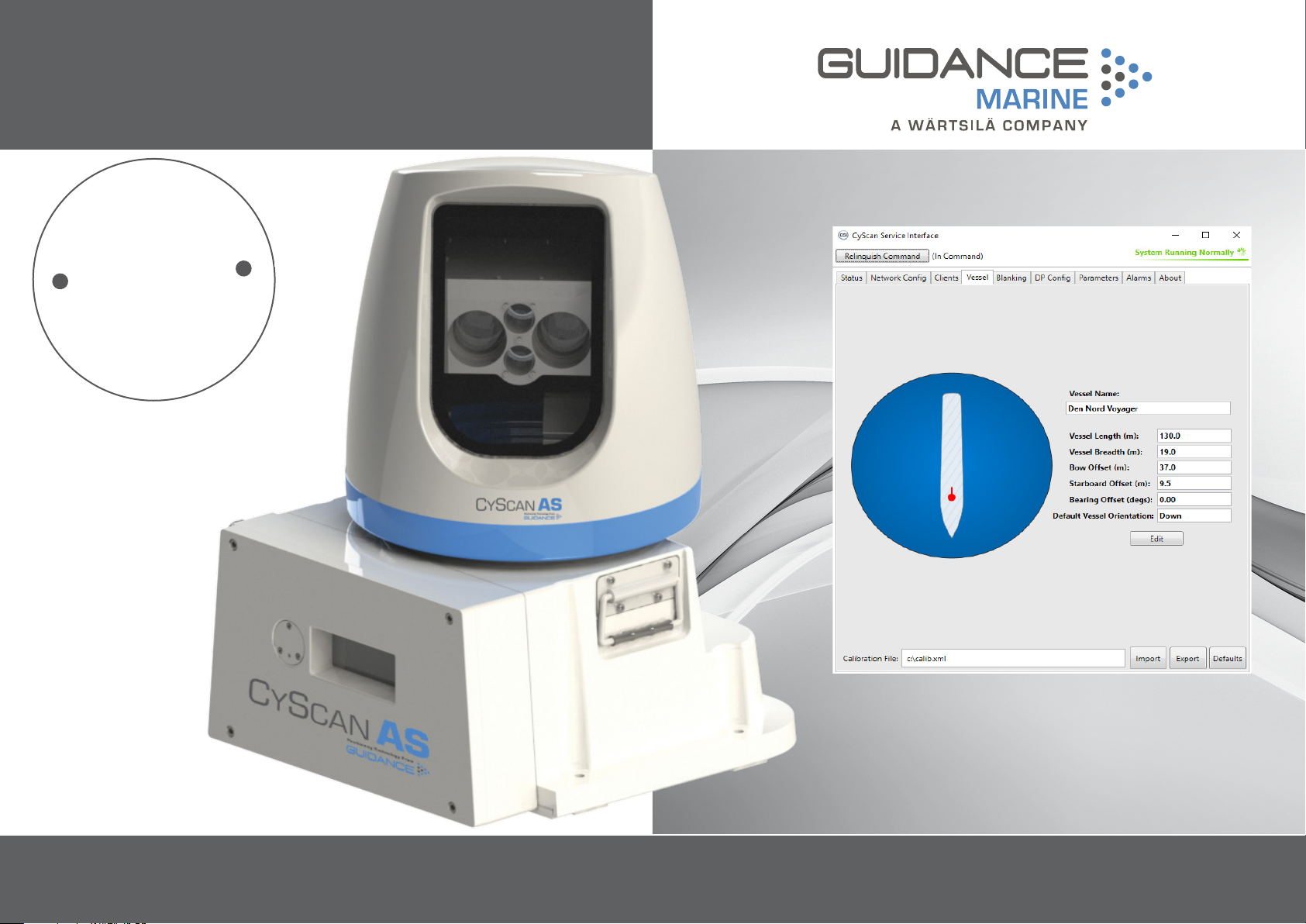
CyScan is a high accuracy relative position reference sensor. It provides positional
information to a vessel’s DP system, allowing it to keep station relative to a target structure
or another vessel.
The CyScan AS system contains the following main parts:
CyScan AS Sensor
•
CyScan Client Software
•
CyScan Targets
•
CyScan AS Sensor
The CyScan AS sensor is a rotating laser scanner. It is mounted on the vessel’s
superstructure; typically on the wheel-house.
The CyScan AS sensor can be installed in three ways:
Ethernet Client, Single Serial DP (see page 19)
•
Ethernet Client, Dual Serial DP (see page 20)
•
Serial Client, Single Serial DP (see page 21)
•
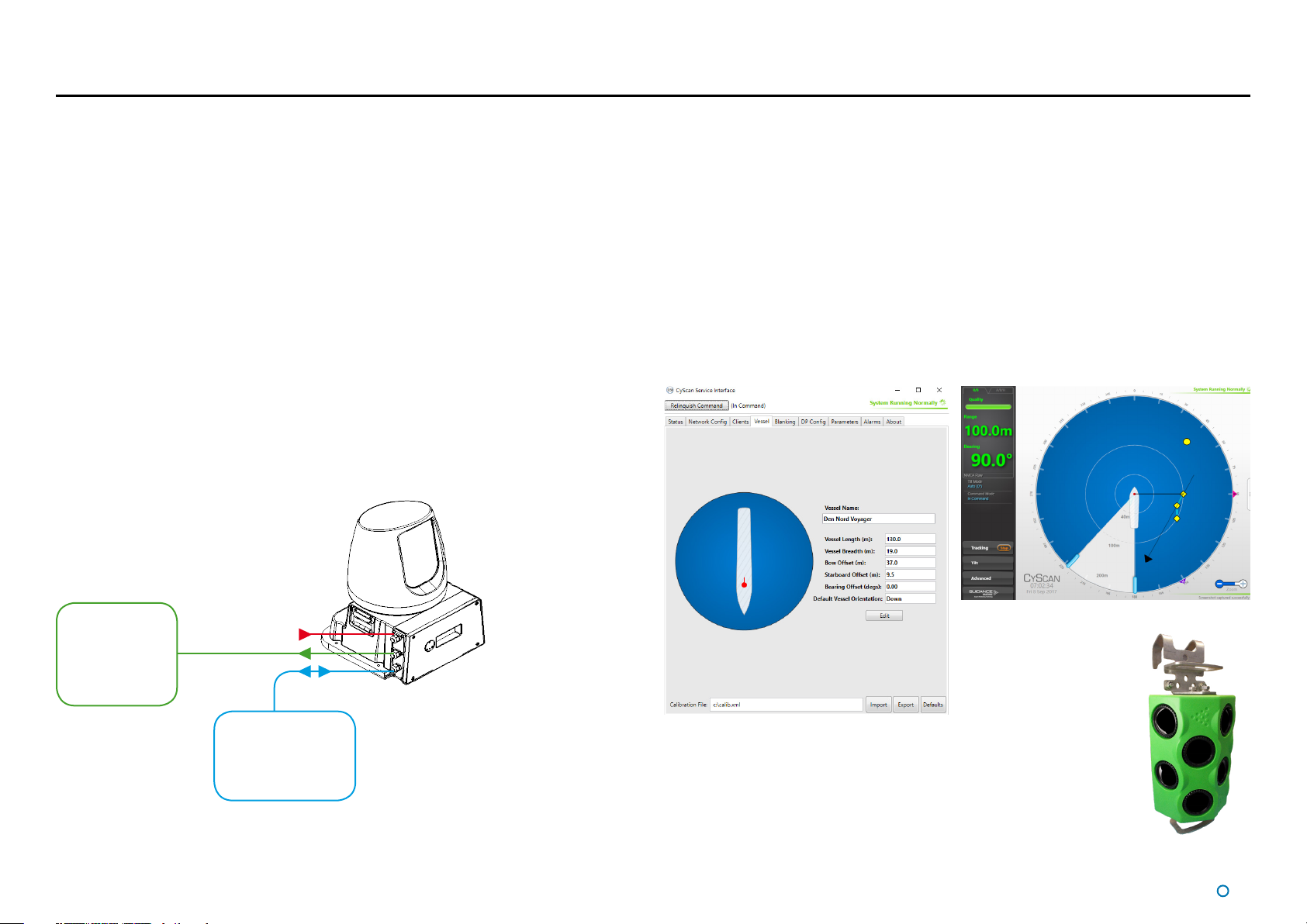
CyScan Client Software
The CyScan Service Interface (CSI) and CyScan Dashboard are software applications
used to configure, control and monitor the CyScan system. They are installed on a marinespecification Type 3 Marine Processor or a computer running Microsoft WindowsTM, usually
mounted on the bridge near to the controls of the vessel’s DP system.
The CyScan Service Interface is used for system configuration and replaces the Service
Access mode of the Dashboard or Console seen in earlier versions of the CyScan system.
The Dashboard gives the DP operator control of the CyScan system and the data stream
being fed to the DP system.
The Ethernet version of the Dashboard can run on multiple computers across a network,
with one Dashboard in Command mode and the others in Monitoring mode.
DP
Power
System
Client
Software
Computer(s)
The key elements of the CyScan system
CyScan
Sensor
CyScan Dashboard
CyScan Service Interface
CyScan Targets
One or more retro-reflective CyScan targets are mounted on the target
platform or vessel. The precise range and bearing of each target is used
to calculate the exact position of the CyScan vessel relative to the target
structure or vessel.
See on page 40 for more detail on CyScan targets.
CyScan Rugged
Prism Target
l
7
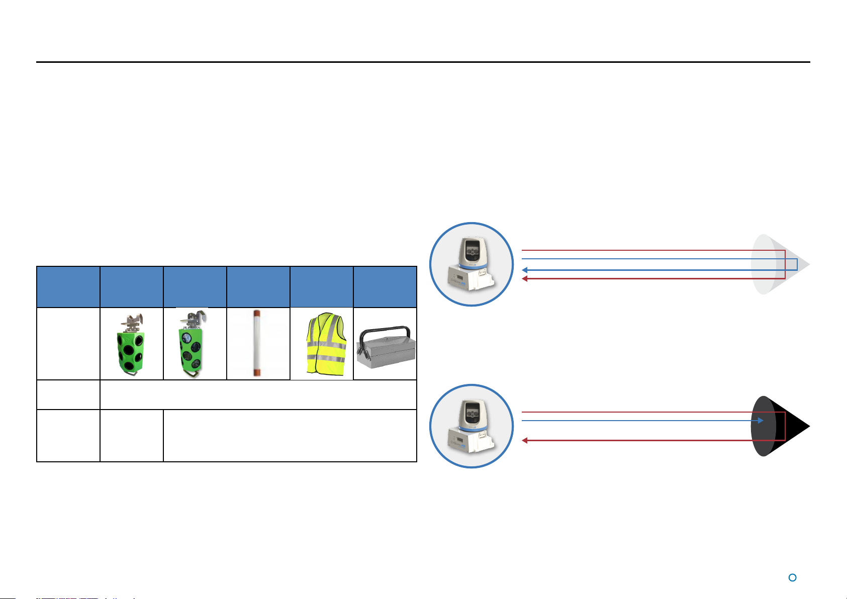
What is Absolute Signature (AS)?
It is well known that laser Position Reference Sensors (PRS) cannot always distinguish
between different types of reflector targets. Standard laser PRS, such as CyScan Mk4,
will detect and track prisms and tube targets as well as all other reflective objects (known
as false targets) in the vicinity. This includes reflective metallic items or high-vis jackets
of workmen. The standard system cannot identify what type of target it is detecting or
tracking.
This can have potentially dangerous consequences when a vessel is station keeping
using Dynamic Positioning (DP). If a moving false target is being tracked by the laser PRS
(such as a workman’s jacket or a toolbox) the DP system will respond to this and make
adjustments to the position of the vessel which can result in a collision.
The patent protected Absolute Signature (AS) technology can completely eliminate the
ambiguity. When a CyScan AS sensor is used in conjunction with an AS prism, the system
can uniquely identify the AS prism target from all the clutter of other reflective objects in the
scene. No other laser technology can do this.
Sensor AS Prism Standard
Rugged
Prism
Tube Target High-Visible
Jacket
Other
Reflective
Objects
How does AS work?
The AS prism has a black tinted lens filter which gives it a unique signature that the CyScan
AS sensor can exclusively identify as the AS prism target.
Unlike a standard laser sensor which only has one laser beam, the CyScan AS sensor sends
out two lasers that have different wavelengths. The filter on the AS prism blocks one of
these lasers, but allows the other laser to be reflected, the same way that your sunglasses
block UV light, but let visible light through.
This means that only one reflected laser beam is detected by the AS sensor. All other
reflective objects and targets reflect both laser signals.
CyScan AS sensor used with any reflective target detects both laser reflections:
The CyScan AS sensor can be used like a standard CyScan if no AS prism is available.
CyScan AS sensor used with AS prism target only detects one laser reflection – it can
uniquely identify the target:
Standard
Laser PRS
CyScan AS
Sensor
Cannot distinguish between the reflective targets . Will detect and
track any reflective target.
Uniquely
identifies
and tracks
AS Prism
Standard targets and false reflections are
distinguished from the AS Prism.
Benets of AS
Guaranteed ‘signature lock’ between the CyScan AS sensor and the AS prism target
•
The likelihood of incidents due to false reflections is reduced to zero
•
The AS Dashboard user interface automatically identifies the AS Prism targets which
•
reduces the workload for the DPO in identifying and selecting the targets
AS prism targets work with all other laser sensors and perform like any other standard prism
target.
l
8
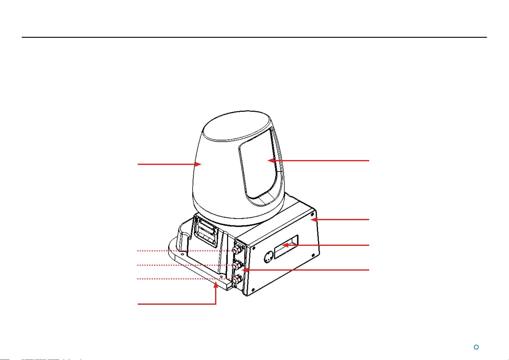
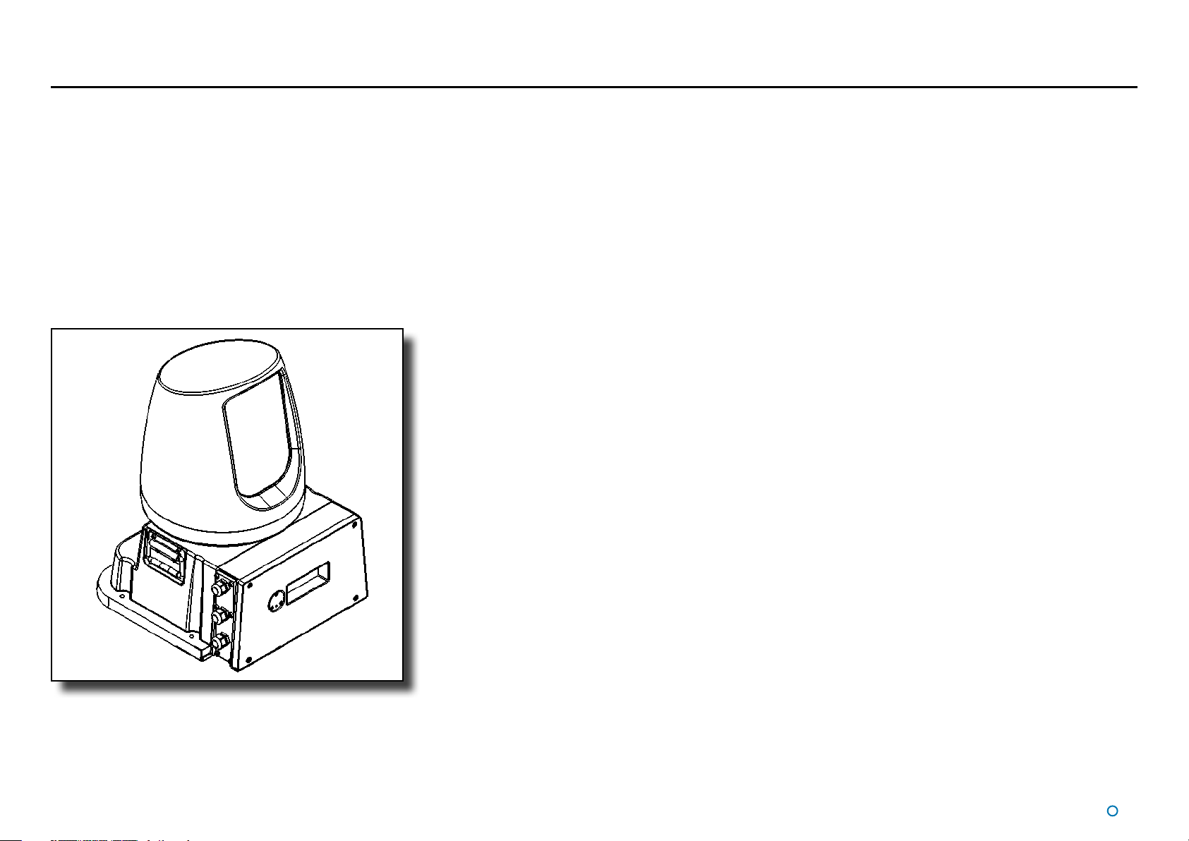
CyScan Sensor Part Names
The diagram below shows the key parts of the sensor unit and the various names that are
used throughout this guide:
Rotor
Power
DP Feed
Client Data
Base Plate
Rotor Window
Access Cover
Sensor Information
Display
Cable Gland Plate
l
9

CyScan Sensor Part Names (Continued)
Power
DP Feed 2
DP Feed 1
Client Data
Alternative model with 4 cable glands.
l
10
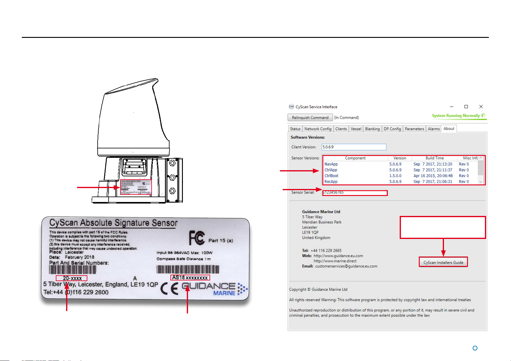
Serial Numbers & Software Versions
Serial numbers and Software Version Numbers are used to identify the hardware configuration and product revision of each CyScan unit. They will be requested by Guidance Marine in the
event of an application service support call to the company.
Product Label
The Part Number and
Serial Number can be
found on the product label
fixed to the CyScan unit,
see right.
CyScan Sensor
Product Label
Software Version Information
The About tab of the CyScan Service Interface displays software version
information and the sensor serial number.
Software Version Information
CyScan Sensor
Serial Number
Installing the latest software
updates will guarantee that they
have an up to date manual
CyScan Sensor
Part Number
CyScan Sensor
Serial Number
l
11

Installing the Sensor Hardware
This section contains the following pages:
Where to Mount the Sensor (page 13)
•
Sensor Dimensions and Mounting Template (page 14)
•
l
12
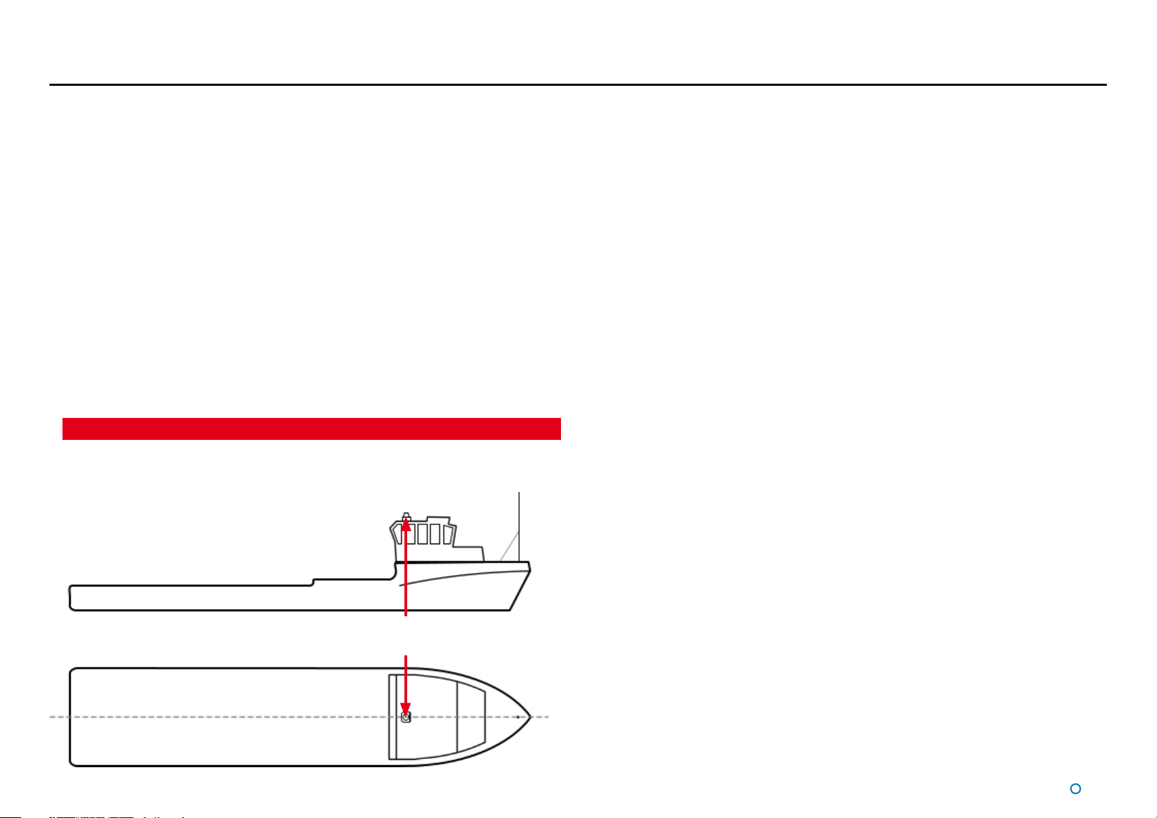
Where to Mount the Sensor
Sensor Mounting Locations
The CyScan system is designed for permanent or semi-permanent installation on-board a
vessel. Often, a custom-fabricated plinth is used to provide the optimum height and location
for mounting the CyScan sensor.
On all types of vessel the sensor should be mounted:
With an unobstructed view in the expected direction of the target structure or vessel.
•
Well above sea level to prevent swamping or immersion.
•
On a flat, rigid, horizontal surface able to support 30kg and receive 4x M8 fixing bolts.
•
Allowing for easy access to the connector board and Sensor Information Display.
•
Clear of VHF emergency band antennae, S-band and X-band ship’s radars (5 meter
•
minimum horizontal separation from RF sources (VHF, S and X band) and ideally vertical
separation of one deck ).
Clear of likely emissions from exhausts or other particulate sources to reduce the need
•
for cleaning the optical windows.
The field of view off the vessel should be clear of retroreflective material
•
Exhaust emissions contain particulates which will degrade the optics.
The sensor should be mounted with the Access Cover (see page 9). Any deviation from the
centre-line alignment must be corrected in the CyScan Service Interface.
A typical mounting position is above the wheelhouse for a vessel with a
superstructure like that of a platform supply vessel.
l
13
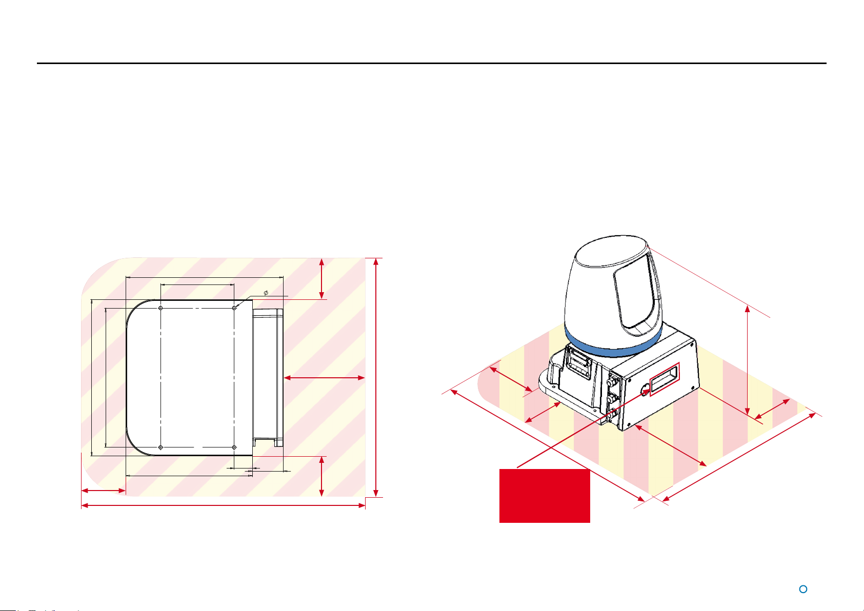
Sensor Dimensions and Mounting Template
Sensor Clearance
The exact dimensions of the CyScan AS unit’s footprint are shown below.
Additional information shown on the right could be beneficial when mounting the CyScan
unit. Please refer to Document No: 94-0062-4 CyScan Mounting Template to view the
information in larger format.
407
190
4 x
9 THRU
360
405
300
705
Mounting Template
Mount the baseplate horizontally.
Allow 150mm
clearance for
access to the
rotor screws.
150
Allow a sensor height of 563mm
from the mounting plate, plus an
additional 30mm clearance to
remove the rotor from the shaft.
563
150
327
857
150
150
Allow 150mm
clearance at either side
of the unit for use of
the lifting handles.
47
80
150 150
Ensure that the
display screen is
not obstructed
when installed
857
300
705
Allow 300mm
clearance at the
access cover to
manoeuvre internal
assemblies in/out.
All dimensions in mm
NOT TO SCALE
14
l

Installing the Cables
This section contains the following pages:
Cable Specifications (page 16)
•
UPS Specifications (page 17)
•
Legacy CyScan Sensor Connections (page 18)
•
Legacy Client and DP Feed Connections - Ethernet Client, Serial DP (page 19)
•
Legacy Client and DP Feed Connections - Ethernet Client, Dual Serial DP (page 20)
•
Legacy Client and DP Feed Connections - Serial Client, Serial DP (page 21)
•
CyScan AS Sensor Connections (page 22)
•
CyScan AS Client and DP Feed Connections - Ethernet Client, Serial DP (page 23)
•
CyScan AS Client and DP Feed Connections - Ethernet Client, Dual Serial DP (page 24)
•
CyScan AS Client and DP Feed Connections - Serial Client, Serial DP (page 25)
•
l
15
Cable Specications
The CyScan system is usually supplied without the cables that are necessary to connect the sensor to the DP system and the Client Software computer(s). Guidance recommends that
flexible multicore cables are used in all applications. Cables should meet the requirements of IEC 60228 Class 2 or Class 5. Cables must be supplied and fitted by the installer to match the
particular requirements for each vessel. All cables should be properly secured.
The cable glands will fit cables from 7-13mm diameter.
All cables should be
• External marine standard including UV and chemical resistance
• 500V rated voltage
• Diameter 7-13mm
• Operate between -40°C to +80°C.
Note: Data cables should not be run across or next to power cables to avoid signal
interference problems.
Cable Description Guidance Marine Part Numbers (40m lengths)
Serial Signal Wiring to DP
System
Serial Signal Wiring to
Client Software Computer
Ethernet Connection to
Client Software Computer
Minimum 5-core shielded data
cable.
CAT 5e screened cable (maximum
length 90m).
33-0122-3
33-0124-3
L45581-B42-K8 Leoni L Trailing Cable 4X2X0.15
Power Cable 3 core power cable.
Refer to the cable routing diagrams on page 44 to determine which cables you require.
33-0121-3
Lapp Kabel Stuttgart Olflex Classic 400 CP 3G 1.0
l
16

UPS Specications
The power supply to the CyScan sensor and the computer(s) running the CyScan Service
Interface and Dashboard must come directly from a Un-interruptible Power Supply (UPS),
which will also act as the power disconnection point.
The CyScan system comprises the following components, the UPS system used must meet
these minimum specifications:
CyScan AS Sensor
The UPS must be Marine Type Approved
•
Input Power = 130W †
•
Voltage Range = 85-264 VAC
•
Peak Current draw at 110V = 1.6A
•
Nominal Current draw at 110V = 1.2A RMS
•
Peak Current draw at 230V = 0.7A
•
Nominal Current draw at 230V = 0.6A RMS
•
The CyScan UPS should be able to run on back-up power for at least the same duration as
that specified for the DP System UPS.
The power cable to the CyScan Sensor must be rated to withstand the maximum current
output of the UPS.
† Worst case power consumption when operated at -25°C
Type 3 Marine Processor Power Adaptor
Voltage Range = 100-240V
•
Frequency Range = 50-60Hz
•
Peak Current draw = 1.8A
•
Hatteland Panel PC
Voltage Range = 115 & 230V
•
Frequency Range = 50-60Hz
•
Nominal Current draw at 115V = 0.52A RMS
•
Nominal Current draw at 230V = 0.26A RMS
•
The specifications given above apply when the UPS is connected to a CyScan
system only.
l
17
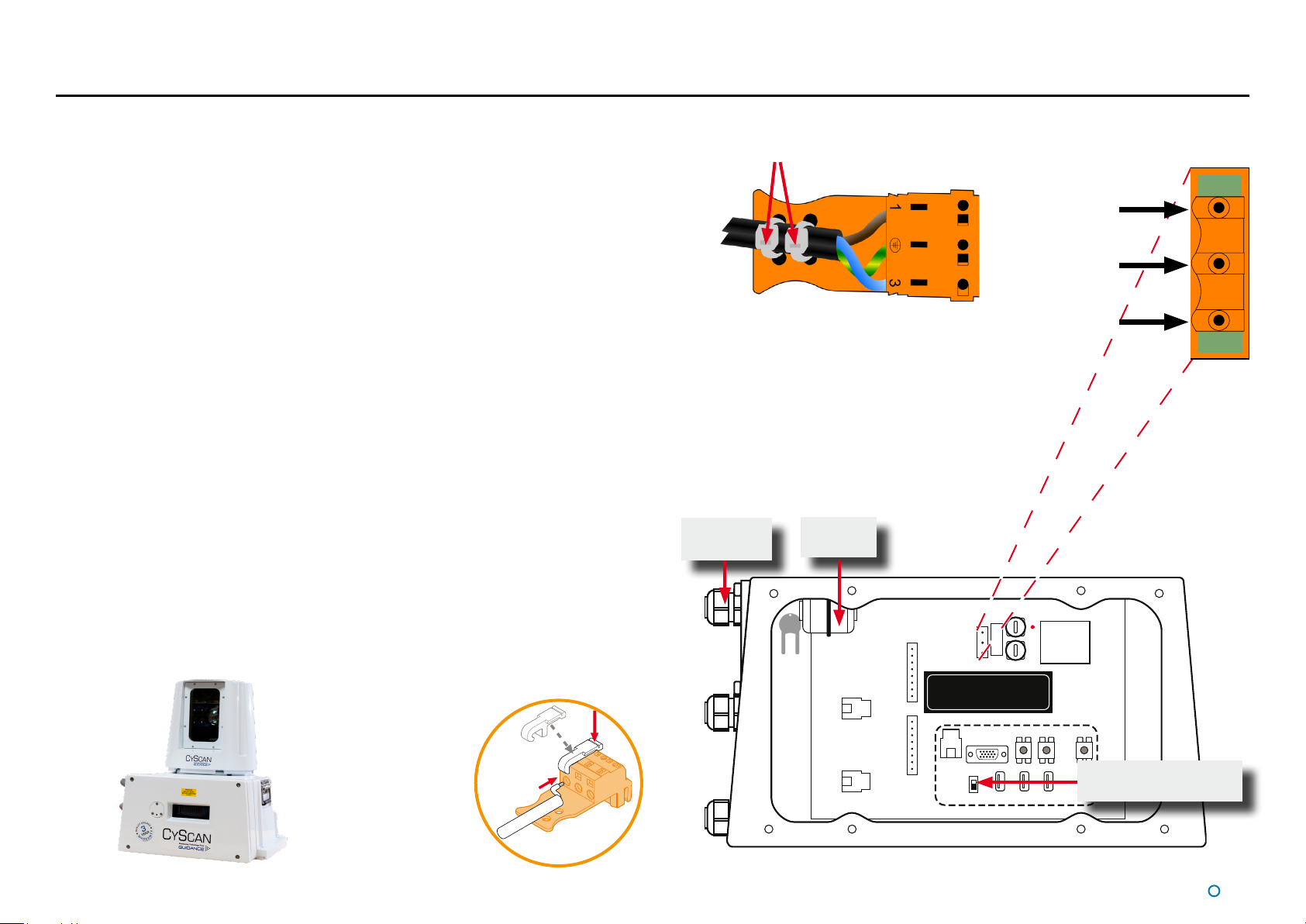
Legacy CyScan Sensor Connections
To Connect a Cable to the CyScan Sensor
1. Remove the 4 screws from the access cover and remove the plate from the sensor unit
to expose the connector board. (See CyScan Sensor Part Names on page9).
2. Remove the screw head from the appropriate watertight cable gland. See CyScan
Sensor Part Names on page9 to identify the correct cable gland.
3. Feed the cable through the screw head and gland.
4. Connect the cable to the correct socket/terminal on the sensor connector board.
5. When all the connections have been made, replace the access cover and tighten all of
the cable glands to ensure a watertight seal.
Connecting the Power Cable
1. Having fed the cable through the watertight cable gland, use the key provided to open
the ferrite and pass the cable through the centre of the ferrite.
2. Close the ferrite securely and ensure it is firmly attached to the inside of the CyScan
casing to prevent excessive movement.
3. Strip 10mm of insulation from the end of each of the three cable cores.
4. Connect the 3 cores to the appropriate terminals as labelled on the terminal block
(see right).
5. When the connections to the terminal block have been made, use two cable ties to
secure the terminal block and cable together.
6. Plug the terminal block securely in to the socket on the connector board as shown on
the right.
Cable ties
Watertight
cable gland
Terminal block with cable cores
connected
Ferrite
and key
Power terminals on
connector board
Live
Earth
Neutral
To Connect Cables to
Power/Serial Plugs:
Operation Lever-tool (part
number: 190-0003-4)
into slot above
connector-hole in plug.
Whilst holding down
lever, insert cable end
into connector-hole.
Release and remove
the lever-tool.
Base of CyScan with the access cover removed to expose the connector board
BOW/STERN switch
see page 13
l
18
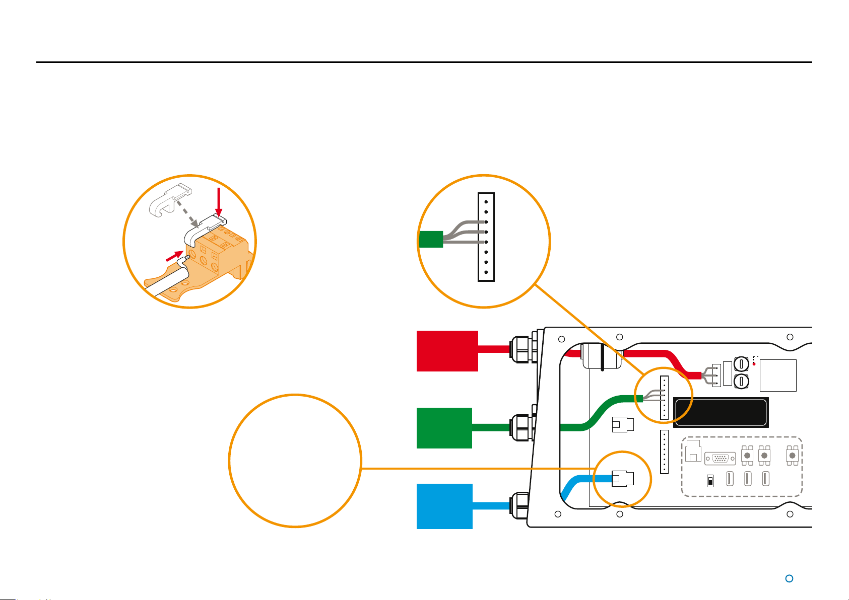
Legacy Client and DP Feed Connections - Ethernet Client, Serial DP
For an Ethernet conguration sensor, connect the Ethernet cable to Ethernet 0 and the DP serial cable to Serial 1:
Connect Ethernet Port 0 to the Marine Processor and Serial Port 1 to the DP system.
Configure the serial connections as shown below:
To Connect Cables to
Power/Serial Plugs:
Operation Lever-
tool into slot above
connector-hole in
plug.
Whilst holding
down lever, insert
cable end into
connector-hole.
Release and remove
the lever-tool.
†Contact Guidance
Marine if
alternative settings
are required.
Client Network Protocol:
Ethernet
Default Ethernet Settings:
IP Address: 192.168.0.86
Subnet Mask:
255.255.255.0
RS422 Link
9600 baud
8 bits
1 stop bit
No parity
*+24V output on pin 8 of
both serial ports can be
used to power a 100mA data
converter, if required.
Ferrite Bead
Ethernet 1
Serial 1
Power
Fuses
VFD Screen
Power LED
Serial 1
DP
Feed
Mains Power
85–264V AC
45–65Hz 45W
RS422 Link
to Vessel’s
DP System
1 RX2 RX+
3 TX4 TX+
5 GND
6 Test
7 GND
8 +24V
*
†
Stern
Bow
Service Connections
Ethernet
Link to
Marine
Processor
Serial 0
Ethernet 0
l
19
 Loading...