

Page 1
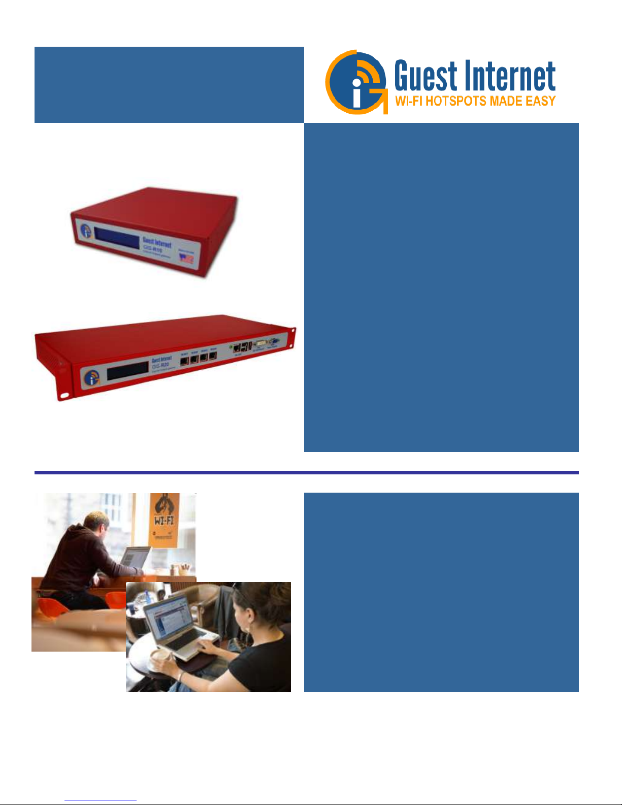
Advanced Hotspot
Gateway Products
WiFi Hotspots made easy
so you can provide a
better Internet service for
your guests and visitors
A Guide to the Operation
of Guest Internet Hotspot
Gateway Products
Revision 2.3 Software
Manual Revision 2.3.7
Guest Internet Solutions is a business unit of Fire4 Systems Inc., a Florida Corporation. Copyright © Fire4 Systems Inc., 201 3. All rights reserved. Fire4,
Guest Internet, and the respective logos are registered marks of Fire4 Systems Inc. All other registered marks, trademarks, service marks and logos are
the property of their respective holders. Information here is subject to change without notice.
Page 2

FCC STATEMENT
Class A Digital Device
This equipment complies with Part 15 of the FCC rules. Operation is subject to the
following conditions.
1. The device may not cause harmful interference.
2. This device must accept any interference received, including interference
that may cause undesired operation.
Federal Communications Commission Notice
This equipment complies with the limits for a Class A digital device, pursuant to Part
15 of the FCC Rules. These limits are designed to provide reasonable protection
against harmful interference.
The equipment can radiate radio frequency energy. If not installed and used in
accordance with the instructions in this manual, it may cause harmful interference to
radio, television or telecommunications reception, which can be determined by
turning the equipment off and on. The user is encouraged to try and correct the
interference by one or more of the following measures.
Reorient or relocate the receiving antenna
Increase the distance between the equipment and the receiver
Power the equipment via a different electrical circuit from that which the
receiver is connected
Consult the dealer who installed the equipment, or an experienced radio
frequency technician
Modifications
The FCC requires that no changes or modifications may be made to this device that
are not expressly approved by FIRE4 Systems Inc, and Guest Internet Solutions. Any
unauthorized changes may void the users authority to operate the equipment.
Guide to Operation Copyright © Fire4 Systems, Inc., 2013. All Rights Reserved www . guest - internet . com 2
Page 3

Contents
1
2
3
4
5
6
7
8
9
10
11
12
13
14
15
16
17
18
19
20
21
22
23
24
25
26
27
28
29
30
31
32
33
34
35
36
37
38
39
Introduction
Provide a Public Internet Hotspot Service for your Guests and Visitors
Principal features of Guest Internet Gateway Products
Choose to Provide Unlimited Internet Access or Controlled Internet Access
Features of Controlled Guest Internet Access
Your Guest Internet Gateway Product Contents
Characteristics of the GIS-K1+ Gateway Product
Characteristics of the GIS-K3 Gateway Product
Characteristics of the GIS-R3 Gateway Product
Characteristics of the GIS-R5+ Gateway Product
Characteristics of the GIS-R6+ Gateway Product
Characteristics of the GIS-R8 Gateway Product
Characteristics of the GIS-R10 Gateway Product
Characteristics of the GIS-R20 Gateway Product
Characteristics of the GIS-TP1 Ticket Printer Product
Discontinued products
Installation of Guest Internet Gateway Products
Powering the Gateway Products
Switching the Gateway Product on for the First Time
Installing the Gateway product in the Computer Network
Connecting Your Computer Browser to the Guest Internet Product
The Quick Start Wizard: Get Your Gateway Working Quickly
The Quick Start Wizard: Check the Internet Connection
The Quick Start Wizard: Set the Time Zone and Password
The Quick Start Wizard: Enter Your Business Information for the Login Page
The Quick Start Wizard: Select Disclaimer or Code Access
The Quick Start Wizard: Completing the process
Operating the Guest Internet Gateway Unit
Using Advanced Functions to Access Additional Fe atures
Login for Access Code Generation and Management
Status Functions: System Information
Status Functions: Connected Users
Status Functions: Usage Reports
Status Functions: Billing Reports
Management Functions: Manage Codes
Management Functions: Hotspot Availability
Management Functions: Change Password
Management Functions: Reboot System
Advanced Settings: Login Settings
Advanced Settings: Login Messages
Guide to Operation Copyright © Fire4 Systems, Inc., 2013. All Rights Reserved www . guest - internet . com 3
Page 4

40
41
42
43
44
45
46
47
48
49
50
51
52
53
54
55
56
57
58
59
60
61
62
63
Advanced Settings: Credit Card /PayPal
Advanced Settings: Edit Disclaimer
Advanced Settings: Time Zone
Advanced Settings: Email Settings
Advanced Settings: Content Filter
Advanced Settings: Dynamic DNS
Advanced Settings: Bandwidth Control
Advanced Settings: Network Interfaces
Advanced Settings: Wireless Settings: for the GIS-K1+/K3 product only
Advanced Settings: WAN Settings: GIS-R10 to GIS-R20 only
Advanced Settings: LAN Settings: GIS-R10 to GIS-R20 only
Advanced Settings: Firewall
Advanced Settings: Port Forwarding
Advanced Settings: Monitoring / Alerting
Advanced Settings: Hostname
Advanced Settings: Allowed IP List
Advanced Settings: Allowed MAC List
Advanced Settings: Blocked MAC List
Advanced Settings: Ticket Printer Setup
Advanced Settings: Upgrade Firmware
Advanced Settings: Backup and Restore
Reset the Product Configuration to Factory Defaults
Programmers Reference: Access Code Request API for PoS/PMS Systems
Linux Distribution
Guide to Operation Copyright © Fire4 Systems, Inc., 2013. All Rights Reserved www . guest - internet . com 4
Page 5

Introduction
You are planning to use a Guest Internet gateway to provide a WiFi hotspot Internet service for people that frequent your business.
First be aware of an issue with wireless routers that will prevent your WiFi hotspot working if the wireless router is not configured
correctly. Please avoid using wireless routers unless you are familiar with configuring them as bridge mode access points. Note also
that wireless routers intended for residential use have limited range and you will have much better wireless coverage by installing a
commercial grade high power access point.
Our customers requested the new features included with this firmware release (listed below). We work very hard to ensure that our
customers get the product features that they need. We always value feedback from our customers regarding new features that they
would like to have in future versions. If you have a request for a new feature then please contact us at: info@guest-internet.com
with your suggestions.
AVOID USING WIRELESS ROUTERS WITH GUEST INTERNET GATEWAYS
All GIS gateway products authenticate users by issuing an IP address to each user, and recording the MAC address of each users
computer. The GIS gateway requires a wireless access point to be connected for WiFi access. If a wireless router is used to c onnect
users then the login and authentication process will become intermittent. DO NOT use a wireless router such as the Linksys WRT-54G
unless you are familiar with NAT’ing devices and how to disable the NAT’ing service. A wireless router, such as the Linksys WRT-54G,
can be used if (a) the WAN port of the router is left disconnected, and (b) the router DHCP service is disabled.
Always install the GIS gateway together with a wireless access point configured in bridge mode (default mode) to the GIS gate way
LAN port. We recommend that you use high power, long range commercial grade access points with GIS gateway products, such as
those manufactured by Engenius and Ubiquiti.
Wireless routers intended for residential use have a limited range and area of coverage due to low RF power output. Wireless routers
are generally not suitable for a hotel or restaurant wireless Hotspot installation.
UPGRADING EARLIER FIRMWARE
Upgrades are always free:
Guest Internet products can be upgraded to the latest firmware specification free of charge.
Please see our website support page to request a firmware update. Install the upgrade file
using the firmware upgrade feature in the menu. When the upgrade has been initiated leave
the unit powered up for 10 minutes before using it or powering it down. This time is required to
store the new firmware in the processor memory.
NEW GATEWAY FEATURES
Data collection on login
The user login process will have user response fields that can optionally be included in the
login process. On completion of the login process the user responses are sent via email to the
hotspot operator.
GIS-R10/R20 monitoring
The device table has been increased to 100 entries
GIS-R10 / R20 port
forwarding
The forwarding rules table has been increased to 100 entries
Ticket printer
All GIS gateway products can be used with the Guest Internet ticket printer (GIS-TP1) that will
print access codes on demand using any tablet computer.
FUTURE GATEWAY FEATURES
Global Management:
The gateway firmware can be upgraded to become a managed node in the Guest Internet 2tier server based management and accounting system. Guest Internet will offer a server that
includes: central management of devices and groups of devices, central failure monitoring of
devices, comprehensive reporting that includes usage and billing for both devices and groups,
global access codes, and credit card reporting. The management system is suitable for a multidevice, multi-site network and there are no restrictions on the number of managed devices.
Guide to Operation Copyright © Fire4 Systems, Inc., 2013. All Rights Reserved www . guest - internet . com 5
Page 6

1: Provide a Public
Internet Hotspot
Service for your
Guests and
Visitors
Many restaurants, bars, hotels and motels offer free wireless Internet for guests, or charge
guests for the Internet service. Guests and travelers make reservations based on Internet
availability because they have gadgets that use wireless Internet: iPhones®, iPod Touch®,
laptop computers, and Blackberries®
Our products provide an easy and economical solution for any restaurant or lodging
business that wants to begin offering Internet for guests, or wants to upgrade an existing
system.
Restaurant and lodging businesses that already provide Internet for guests can install our
products to improve their Internet service quality and increase returns.
Our low cost products are tough, reliable and very simple to install and can be
used in many different applications
You can brand your Internet service with our easy to use wizard
Use your guest Internet service to advertise your special offers and promote your
website
You can control Internet access to prevent guests abusing the service
Choose to provide free Internet or charge guests for your Internet service
Many locations can benefit by providing Internet services to the public. Business benefits
include improved sales, more returns, and more walk-in customers.
Restaurant
Coffee bar
Public library
Truck stop
Motel
RV park
Visitor center
Public park
University
Student dorms
Marina
Fashion show
Bus station
Trade show
Event reception
Fashion show
Train station
Music concert
Theater
Golf club
Casino
Sports club
Gymnasium
Bookstore
Beach kiosk
Hospital
Airport
Shopping mall
Hotel
Resort
Multi-tenant condo
Church
Internet access can be offered for free or can be charged for by selling access codes.
Advertising can also generate revenue for both free and charged Internet access. Free
controlled access can be provided where authorized customers are provided with access
codes. The duration of access codes is selected when they are generated.
Guide to Operation Copyright © Fire4 Systems, Inc., 2013. All Rights Reserved www . guest - internet . com 6
Page 7
Guest Internet gateway products are very robust and reliable as they are manufactured to
commercial grade standards. Wireless access points can be connected to the gateway to
provide WiFi wireless Internet. Any type of WiFi enabled device can receive the signal:
including PC laptops, MAC computers, netbook computers, iPhones™, and Blackberries™.
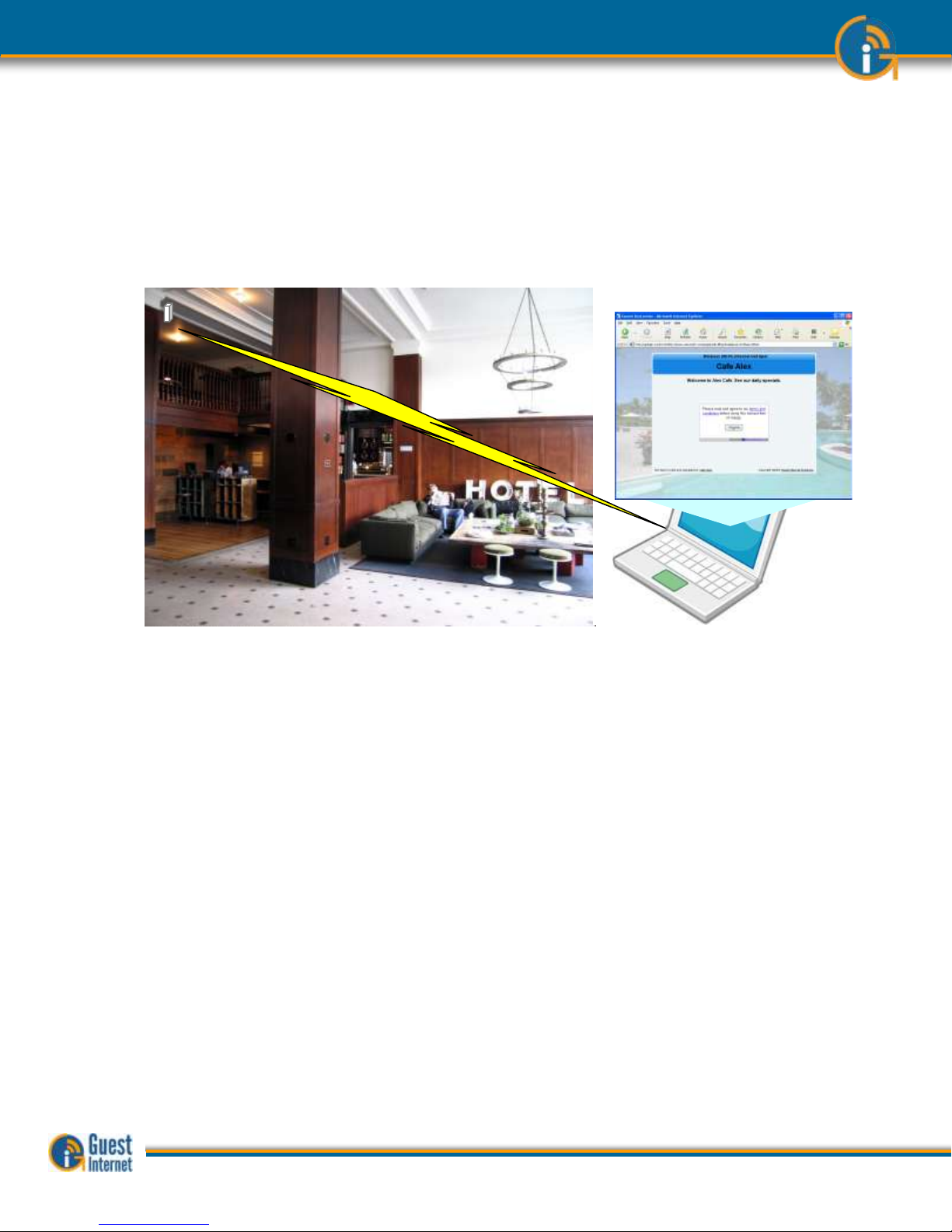
Guest Internet products have a ‘login page’ that requires the user to agree to the terms
and conditions, and possibly pay a fee for an access code. The business owner decides if
Internet will be free or if guests will pay for the service.
The login page is very important for the business providing the Internet service as it has
several essential features:
Brand the Internet service
Provide the business contact information for guests
Encourage the guest to go to the business Web site
Guests must agree to a disclaimer, so the business avoids liability
Advertise products or services provided by the business
Control who uses the Internet with access codes
Charge for Internet access by selling access codes
This manual explains how to install a Guest Internet gateway product and create a custom
login page ready for guests to access the Internet. The only decision you have to make is if
you will provide free Internet or charge for the service.
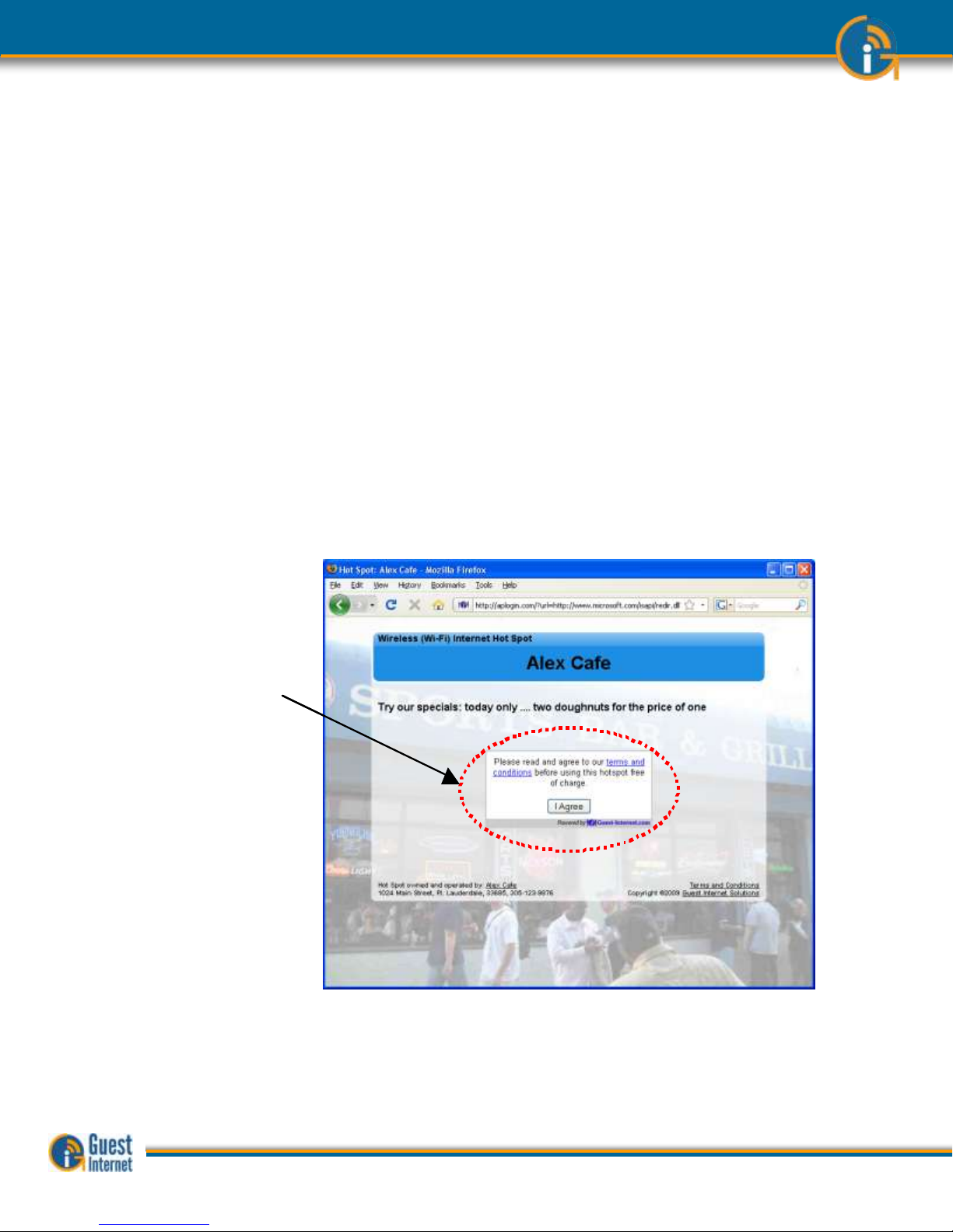
Two login page examples are shown below. The first is an example of unlimited access
where the user has to click on a button agreeing to the terms and conditions. The second
example shows controlled access: the user has to enter an access code that has been
generated using the code management admin page
Login DisplayLogin Display
Guide to Operation Copyright © Fire4 Systems, Inc., 2013. All Rights Reserved www . guest - internet . com 7
Page 8
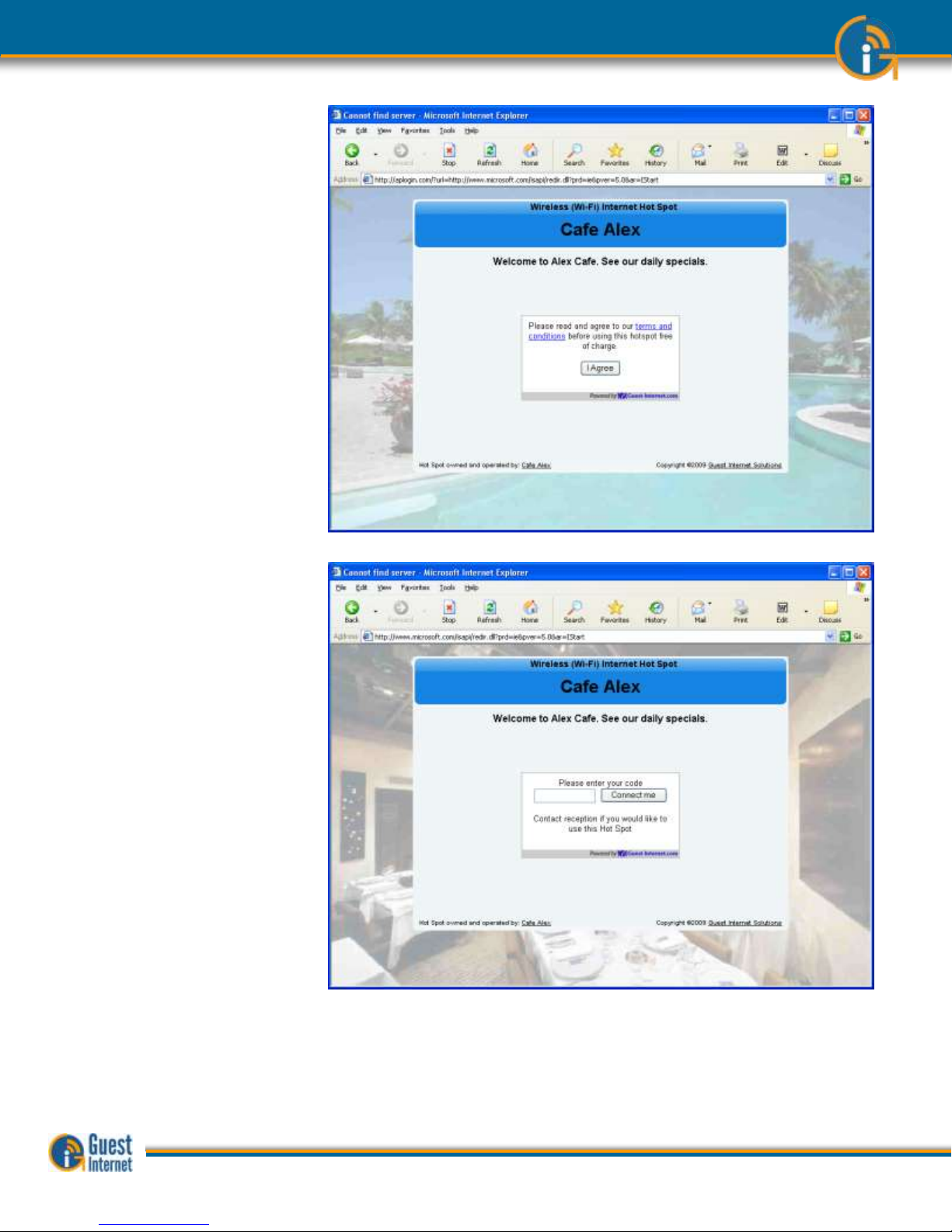
Login Page Example: the
user has to accept the
terms and conditions
Login Page Example: in
addition to accepting the
terms and conditions, the
user has to enter an
access code provided by
the business owner
Guide to Operation Copyright © Fire4 Systems, Inc., 2013. All Rights Reserved www . guest - internet . com 8
Page 9
2: Principal
features of Guest
Internet Gateway
Products
When any business provides an Internet service for guests, visitors and customers, it is very
important to prevent abuse of the services, otherwise bad things can happen;
People are using your Internet service without your consent.
A free service can become a headache if users start complaining about the poor
performance of the Internet service.
Users start surfing inappropriate website in public areas.
The DSL or Cable service provider can threaten to disconnect the service because
users are sharing illegal files.
A free service starts costing the business a significant amount of money as use is
far greater than expected
The Hotspot gateway give you control of the Internet service that you provide for your
guests, visitors and customers. You can prevent unauthorized use, and prevent any
authorized user abusing the service.
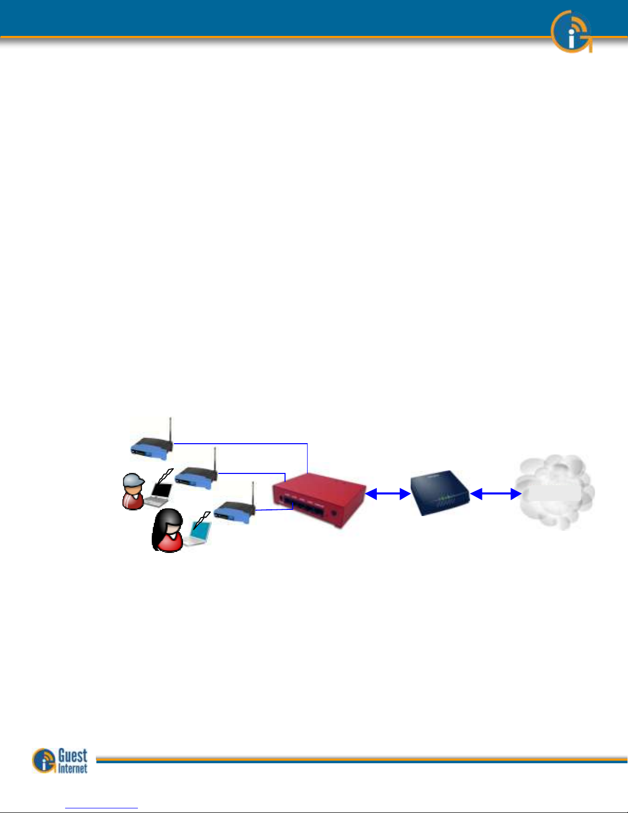
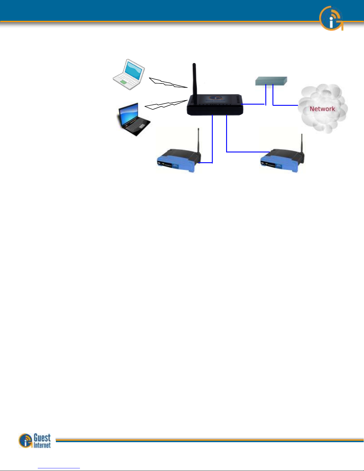
The Hotspot gateway is installed in your network between the wireless access point, and
the DSL or Cable router. See the diagram below. All communications between your users
and the Internet flows through the Hotspot Gateway. The gateway allows Internet access
for authorized users, and blocks people not authorized. The gateway also controls how
users access the Internet. You choose how your users will access the internet by choosing
to set the features described in this manual.
The gateway is very easy to setup and use. A setup Wizard will be displayed on your
computer the first time that you connect your computer to the gateway. Simply follow the
steps described in the Quick Start Guide that is shipped with the product.
Connecting the Hotspot
Gateway
Choosing the Right Hotspot
Gateway
Guest Internet manufactures a range of Hotspot gateways that provide different levels of
performance and features. The gateway performance is specified as the number of users
that can use the Hotspot simultaneously. This is called the maximum number of concurrent
users. The maximum number of concurrent users can only be reached when the Internet
connection has a minimum speed. The maximum number of concurrent users is also
reduced when several users are downloading large files such as video or music files. The
following summary (next page) lists the Guest Internet products, and the parameters for
each product.
Internet
DSL/
Cable
Wireless access points
Hotspot
Gateway
InternetInternet
DSL/
Cable
Wireless access points
Hotspot
Gateway
Guide to Operation Copyright © Fire4 Systems, Inc., 2013. All Rights Reserved www . guest - internet . com 9
Page 10

Login Page
The login page is the most important feature of the Hotspot gateway. All Guest Internet
gateways provide three levels of login page customization;
Twelve pre-prepared login pages are contained in the gateway, choose one of the
twelve login pages when answering the setup Wizard questions.
Any photo or design background can be uploaded in a JPG format and displayed
as part of your login page. Combine a photo of your business and include your
logo using Photoshop® to create a custom login page.
Design and program your login page using HTML. This procedure takes longer but
gives the best results. Create a login page that looks like your website and then
create a ‘Walled Garden’ to make sure that your users are familiar with your
website.
Disclaimer Text and Editor
When any user connects to the Internet they have to click a button and agree to the terms
and conditions of use. This is very important and protects the service provider from possible
legal action at a later date.
A standard disclaimer text is installed that is appropriate for US laws. A disclaimer editor
permits the text to be modified so that additional requirements can be added, or the text
can be translated to a different language.
Access Codes
The login page can be setup so that the user only has to click on a button to agree with the
terms and conditions, however there is no control over who can access the Internet.
Alternatively the gateway can be setup in the controlled access mode. Users can be
authorized to access the Internet by generating access codes and giving one to each user.
Access codes can have a time duration from 30 minutes to 180 days and can also be
unlimited. An access code can also be terminated at any time.
Access codes ensure that only authorized users get access to the Internet.
Reports of Usage
The Hotspot use can be monitored at all times by checking the usage report. This report
shows the number of users connected (obtained IP addresses) and authenticated (entered
a valid access code). The MAC address of each user is shown and the bytes each user has
transferred has shown. Any users abusing the Hotspot service can be easily seen. A check
box is provided to include the users MAC address in the blocked MAC list, thereby
preventing the user accessing the Internet.
Timer/Calendar for
Availability
Many Hotspots are available 24x7 in businesses such as hotels. However the Hotspot in a
dental office should only be available during business hours e.g. 9AM to 5PM). A 7-day
timer /calendar is provided to set availability of the Hotspot in 1 hour increments. Outside
the time that the Hotspot is activated the user will get a login screen with the message
‘Hotspot not available’.
Content Filter
The content filter blocks access to websites that are not suitable for a public environment.
Content filtering services are provided by OpenDNS who have a basic free service and a
range of paid services when advanced content filtering rules are required.
Bandwidth Control
All gateway products provide an overall bandwidth control where download and upload
speeds are set independently. In addition each access code can have a download and
upload speed associated that will override the overall bandwidth setting.
This feature enables tiered use of the Hotspot. A basic free low speed service can be
provided, and augmented with a paid service where the bandwidth is much higher. Typical
applications for such a service are student accommodation and motels.
Firewall
GIS gateway products include a firewall that stops users on the public network (DMZ)
accessing computers in the business network behind the gateway. This feature permits the
public network and business network to share one DSL or Cable circuit.
The GIS-K2 also includes a second firewall that protects business computers (such as PoS
terminals) from access via the Internet.
Remote Management
All gateway products can be managed from a remote location, provided that the network
DSL or Cable service has a fixed IP, and that the DSL/Cable router has a port forwarding
Guide to Operation Copyright © Fire4 Systems, Inc., 2013. All Rights Reserved www . guest - internet . com 10
Page 11

feature to provide access to the Hotspot gateway.
In the case where the DSL or Cable service has a dynamic IP allocation the Hotspot
gateway can be accessed remotely using the DynDNS service. The Hotspot gateway has a
DynDNS agent installed to permit the network IP address to be located via the DynDNS
server. A free test account is provided by DynDNS, and the monthly account fee is very low.
Remote access to Wireless
Devices via Port
Forwarding
The Hotspot gateway port-forwarding feature allows access to devices from outside the
network (wireless access points) that are connected in the public network (gateway LAN
ports). This feature can be used in conjunction with the monitoring and alerting feature to
provide complete remote management and support for the Hotspot network.
Monitoring and Alerting
It is very important that a Hotspot operator find out that a wireless network has problems
before the users do to avoid stressful calls and complaints. All our Hotspot gateways can
monitor LAN attached devices, such as wireless access points, for failure. The failure
warning is sent out via email to the owner or operator of the network. The installer can use
an existing email SMTP service to send the message. In many cases however the network
provider who offers the email service is not the one that the gateway is connected to.
All our gateway products have an agent for the STMP2go service that permits an email to
be sent out from any network. The SMTP2go service has a very low monthly charge and the
benefits of this service far outweigh the small cost.
Allowed and Blocked IP
and MAC Addresses
When any computer connected to the public network must access the Internet without
requiring the login page then the device MAC address is included in the MAC bypass table.
Web sites that must be seen by users without login can have their IP addresses or URL’s
included in the IP bypass table. This feature permits a walled garden login when
implemented in conjunction with the custom login page feature.
When users abuse the Hotspot service then their computer MAC addresses can be blocked.
Look in the usage report table and identify users who are causing a lot of traffic. Then click
on the block MAC address to block that user from the Internet.
Network Port
Configurations
The LAN port configuration is set permanently as a DHCP server. The reason for this is that
IP addresses must be allocated to users as the IP’s are used to authenticate each user.
Other LAN port parameters can all be modified. The DHCP start and end addresses are used
to set the limit for the maximum number of users.
The WAN port can be either a DHCP client or can have a fixed IP. When the content filter is
activated the WAN DNS settings are replaced with those of OpenDNS.
Backup and Restore the
Configuration
The product configuration can be saved in a backup file. If the product is replaced or
configuration changes are made but previous settings are required then the configuration
file can be restored.
The configuration file of any gateway model can be restored on any other gateway model.
All gateway models use an identical file structure.
Upgrade Firmware
Firmware upgrades are released periodically for all gateway products. The upgrades include
new features that have been requested by customers. We also work on product
performance improvements. Firmware upgrades are free for our customers. There will never
be a charge for the latest firmware.
Summary
The tables below summarize the features provided with each product model
Guide to Operation Copyright © Fire4 Systems, Inc., 2013. All Rights Reserved www . guest - internet . com 11
Page 12
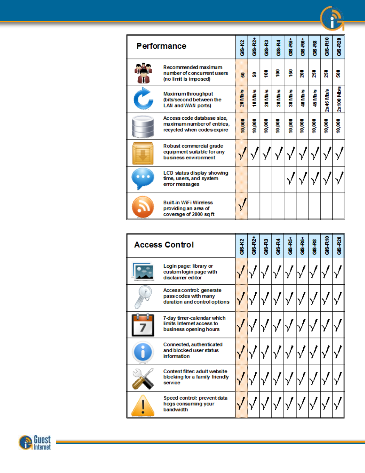
Performance
Access Control
Guide to Operation Copyright © Fire4 Systems, Inc., 2013. All Rights Reserved www . guest - internet . com 12
Page 13
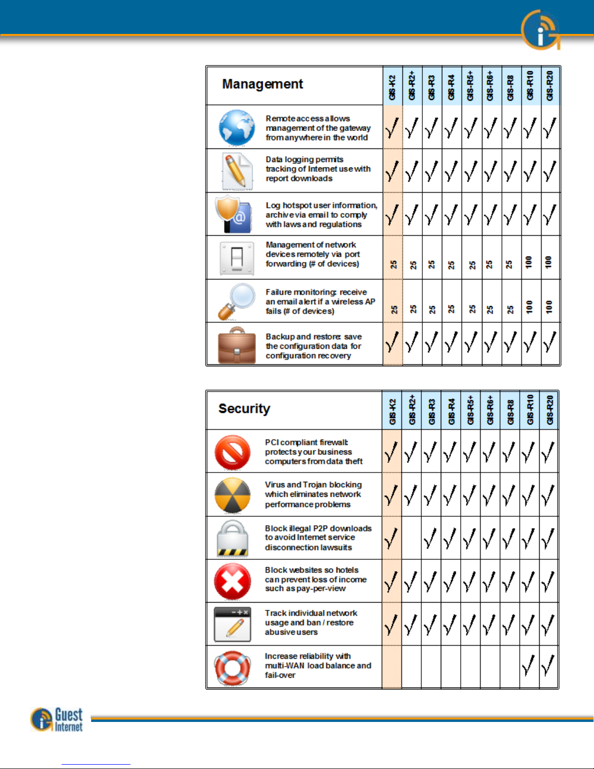
Management
Security
Guide to Operation Copyright © Fire4 Systems, Inc., 2013. All Rights Reserved www . guest - internet . com 13
Page 14
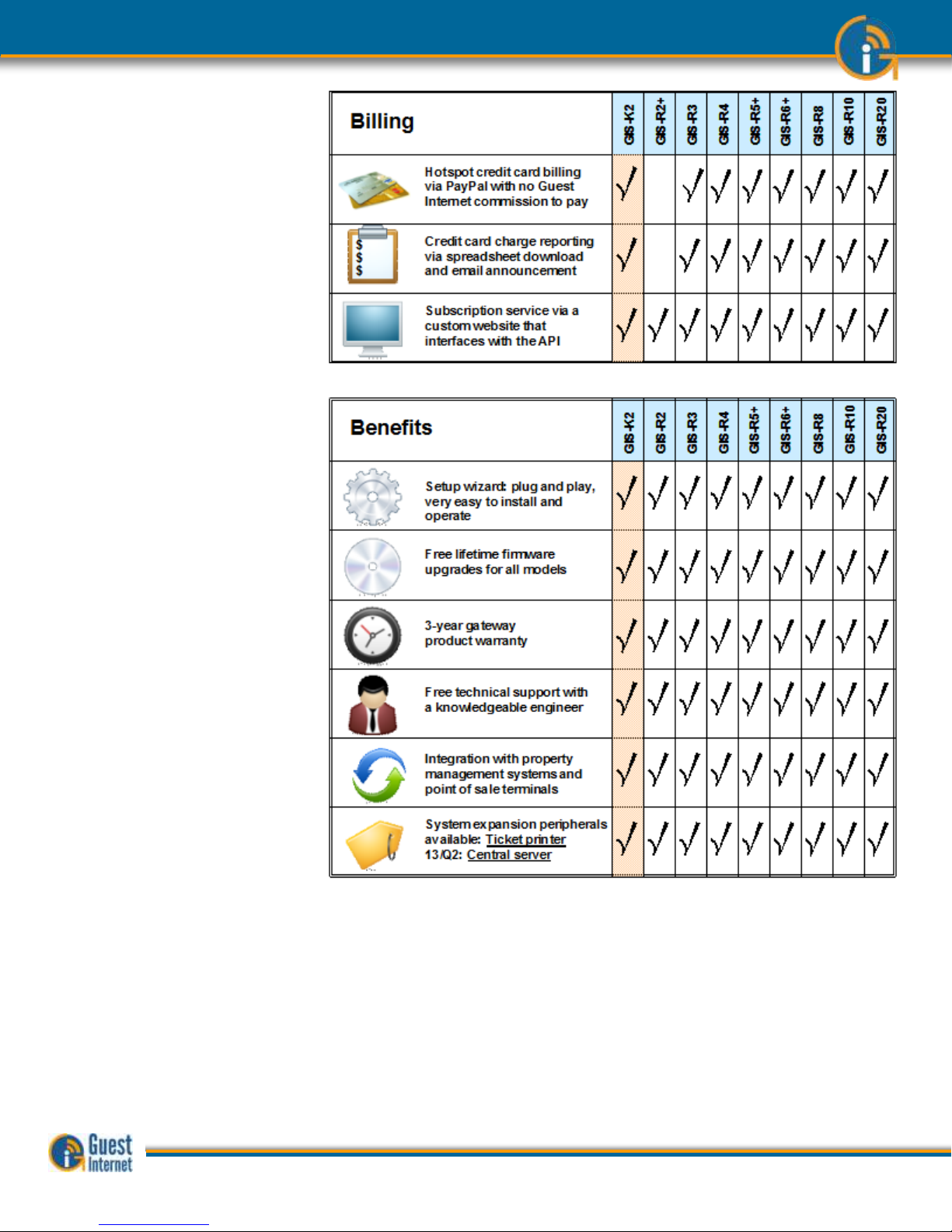
Billing
Benefits
Integrated Solution
Guest Internet is committed to providing customers with an integrated product solution and
we work with partners to achieve this goal.
Partners provide us with value-added channels and with additional functionality that we
don’t provide. Currently we have four functionality partners.
SMTP2go: Additional SMTP services for the gateway mail server
OpenDNS: Content filtering using their DNS service
DynDNS: Remote access service when the gateway network has a dynamic IP
PayPal: Payment services for the credit card billing feature
Guide to Operation Copyright © Fire4 Systems, Inc., 2013. All Rights Reserved www . guest - internet . com 14
Page 15
3: Choose to
Provide Unlimited
Internet Access or
Controlled
Internet Access
Before installing the Guest Internet router product you must decide if you want to provide
unlimited Internet for your guests or if you want to control the access your guests have to
Internet services.
Both unlimited access and controlled access show the guests your login page when their
computer browser opens. Both options also require guests to click on a disclaimer button
accepting the terms and conditions of use. You can edit and change our standard
disclaimer document. The disclaimer is important to protect you if your guests download
copyrighted files or illegal content.
Controlled access also adds the requirement that the guest must enter an access code. You
generate the access codes using the Guest Internet gateway product and you determine
who gets access codes and who does not. If you wish you can charge your guests for
access codes. Please read later sections describing access code generation.
Unlimited Internet Access
When unlimited Internet access has been selected during the configuration wizard setup
process the guest tries to access the Internet but sees the custom login page in the
browser. The custom login page provides business contact information that may be useful
for the guest. A box is shown on the page that requires the guest to click on a button that
says “I agree to the terms and conditions of use”. The guest can read the terms and
conditions of use document. The terms and conditions of use document can be modified to
include local laws (see the later section).
When the guest has clicked on the button then a second page is shown with a button that
says click to access the Internet. When this button is clicked the guest has access to the
Internet. The web page that the guest initially requested (the guests home page) is also
shown.
Login Box
Click on
‘I agree’ to
disclaimer
Login Box
Click on
‘I agree’ to
disclaimer
Guide to Operation Copyright © Fire4 Systems, Inc., 2013. All Rights Reserved www . guest - internet . com 15
Page 16
The figure below shows the screen that the guest sees when the ‘I agree..’ button is
clicked
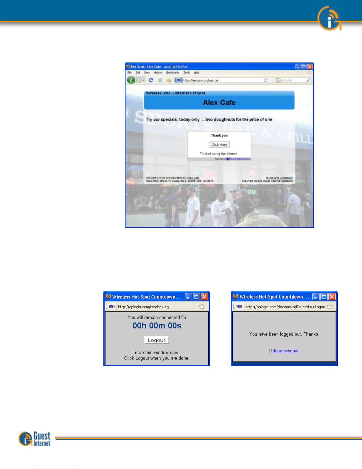
In addition to the browser showing the Web page that was originally requested, a small
window will open that provides a button for the guest to log out of the Internet service.
The figure below on the left shows the window that the guest sees when the ‘Click here’
button is clicked. When the guest has finished using the Internet and clicks on the ‘Logout’
button then the window changes to that shown on the right.
If the guest closes the window showing the remaining time then this information can be
accessed once more by opening a new browser window and typing the URL:
http://aplogin.com
The time that remains for the guest’s access code is shown on the screen.
Guide to Operation Copyright © Fire4 Systems, Inc., 2013. All Rights Reserved www . guest - internet . com 16
Page 17
There is also an alternative to uncontrolled access called open access. In this mode the
login page is not displayed, however all controls are applied to the user, including content
filtering, speed control, P2P blocking and other firewall rules. Open mode is ideal for a
condominium or rental community where a login page is not required, however access
controls are necessary.
There is an option of uncontrolled access where information can be requested from the
user before the user is permitted to access the Internet. Three data fields can be specified,
where the fields might be name, phone number and email address. The email option is
configured to send the information that is collected to the hotspot owner. Note that there is
no verification of the information provided by the user.
Controlled Internet
Access
When controlled Internet access has been selected during the configuration wizard setup
then the login process requires the guest to enter an access code.
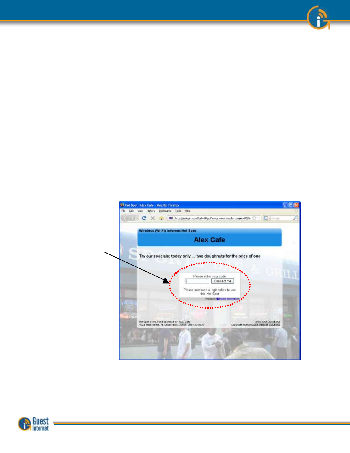
When the guest opens a computer browser to access the Internet the custom login page
will be shown in the browser window. The box shown on the page requires the guest to
enter an access code and then click on a button that says, “I agree to the terms and
conditions of use”.
Access codes are generated within the Guest Internet gateway unit for use with only that
unit: see later sections describing how this is done. Each access code has a fixed duration,
determined when the code is generated. When the time expires the code cannot be
reused.
The login screen that the guest will see is shown below.
When the guest has typed in the access code and clicked on the button then a second
page is shown with a button that says click to access the Internet. When this button is
clicked the guest has access to the Internet. The web page that the guest initially
requested (the guests home page) is also shown.
The figure below shows the screen that the guest sees when the ‘Connect me’ button is
clicked.
Login Box
Enter access code
then click on
‘I agree’ to
disclaimer
Login Box
Enter access code
then click on
‘I agree’ to
disclaimer
Guide to Operation Copyright © Fire4 Systems, Inc., 2013. All Rights Reserved www . guest - internet . com 17
Page 18

In addition to the browser showing the Web page that was originally requested, a small
window will open that provides a button for the guest to log out of the Internet service.
The figure below on the left shows the window that the guest sees when the ‘Click here’
button is clicked. When the guest has finished using the Internet and clicks on the ‘Logout’
button then the window changes to that shown on the right.
If the guest closes the window showing the remaining time then this information can be
accessed once more by opening a new browser window and typing the URL:
http://aplogin.com
The time that remains for the guest’s access code is shown on the screen.
Guide to Operation Copyright © Fire4 Systems, Inc., 2013. All Rights Reserved www . guest - internet . com 18
Page 19

4: Features of
Controlled Guest
Internet Access
Controlled Internet access requires the guest to type an access code into the login page
box. You will generate the access codes using the managed code feature. You can access
the managed code feature by logging in to the gateway product as the administrator;
http://aplogin.com/admin
The screen will request you type in a username (admin) and the password that you will
enter during the wizard setup process.
When you are logged in the select ‘manage codes’ shown in the menu on the left side of
the screen.
You can generate codes that are valid from 30 minutes to 180 days and also unlimited time
codes. You can generate single user or multi-user codes. Only one guest can use a single
user codes and the code cannot be passed from one guest to another. Many guests can
use multi-user codes simultaneously.
You decide who can access your Internet service by giving codes only to guests that you
authorize. You can also sell codes to guests and provide wireless Internet as a paid service.
Some examples are included here to illustrate how codes can be used
1. Restaurant: Prevent guests at the restaurant next door using your Internet service
by creating a one-day multi-user code that you can give to your guests when they
ask for Internet access. Create a different multi-user code each day.
2. Hotel: Free Internet for guests; generate a unique code to give to each guest for
the length of the stay. However if a visitor using the conference room wants to
use the Internet then charge for a code (e.g. $10/day).
3. Coffee bar: charge guests for Internet, each day download access codes and print
onto adhesive labels.
Use your Internet service as a tool to attract customers. For example, if your competitor is
charging for Internet then offer free Internet.
Take care how you offer Internet service for guests. For example a coffee bar that offers
free unlimited Internet might find that guests are occupying tables to use the Internet and
not buying coffee or food. This problem can be easily solved using Guest Internet gateway
products. Give 30-minute free codes at the checkout, and state that codes are given only
with a purchase. The guest will be blocked from the Internet after the 30-minute code
expires and the only way for the guest to continue using the Internet is to make a second
purchase.
Guide to Operation Copyright © Fire4 Systems, Inc., 2013. All Rights Reserved www . guest - internet . com 19
Page 20

5: Your Guest
Internet Gateway
Product Contents:
Your Guest Internet gateway product contains several components that have to be installed
and connected to make the system work. Your product package contains the following
components.
Rapid start guide (Please read first)
Gateway unit
Ethernet cable
Power supply
When you receive your Guest Internet product first check that you received all the parts
listed above.
If one of these items is missing then please inform our customer support immediately;
contact information is provided on our website.
This manual is downloaded from our Web site to ensure that you always get the latest
version. See the manual download URL on the rapid start guide card or copy this link:
http://www.guest-internet.com/manual
Current Products
The Guest Internet product range extends performance from 50 concurrent users up to
500 concurrent users. The current product list is as follows:
GIS-K1+ Wireless gateway for up to 25 concurrent users
Applications include bars, restaurants, dental offices
GIS-K3 Wireless gateway for up to 50 concurrent users
Applications include bars, restaurants, dental offices
GIS-R3 Wireless gateway for up to 100 concurrent users
Applications include medical clinics, caampgrounds, churches
GIS-R5+ Wireless gateway for up to 150 concurrent users
Applications include visitor centers, marinas, theaters
GIS-R6+ Wireless gateway for up to 200 concurrent users
Applications include hotels/motels, RV parks, large retail stores
GIS-R8 Wireless gateway for up to 250 concurrent users
Applications include larger hotels, train stations, small trade shows
GIS-R10 Wireless gateway for up to 250 concurrent users with dual WAN
Applications include larger hotels, conference centers, high reliability
GIS-R20 Wireless gateway for up to 500 concurrent users with dual WAN
Applications include trade shows, resorts, airports, high reliability
GIS-TP1 Access code ticket printer
A summary of the product range is presented on the following pages.
The ticket printer accessory shown here can be connected to any gateway.
Guide to Operation Copyright © Fire4 Systems, Inc., 2013. All Rights Reserved www . guest - internet . com 20
Page 21
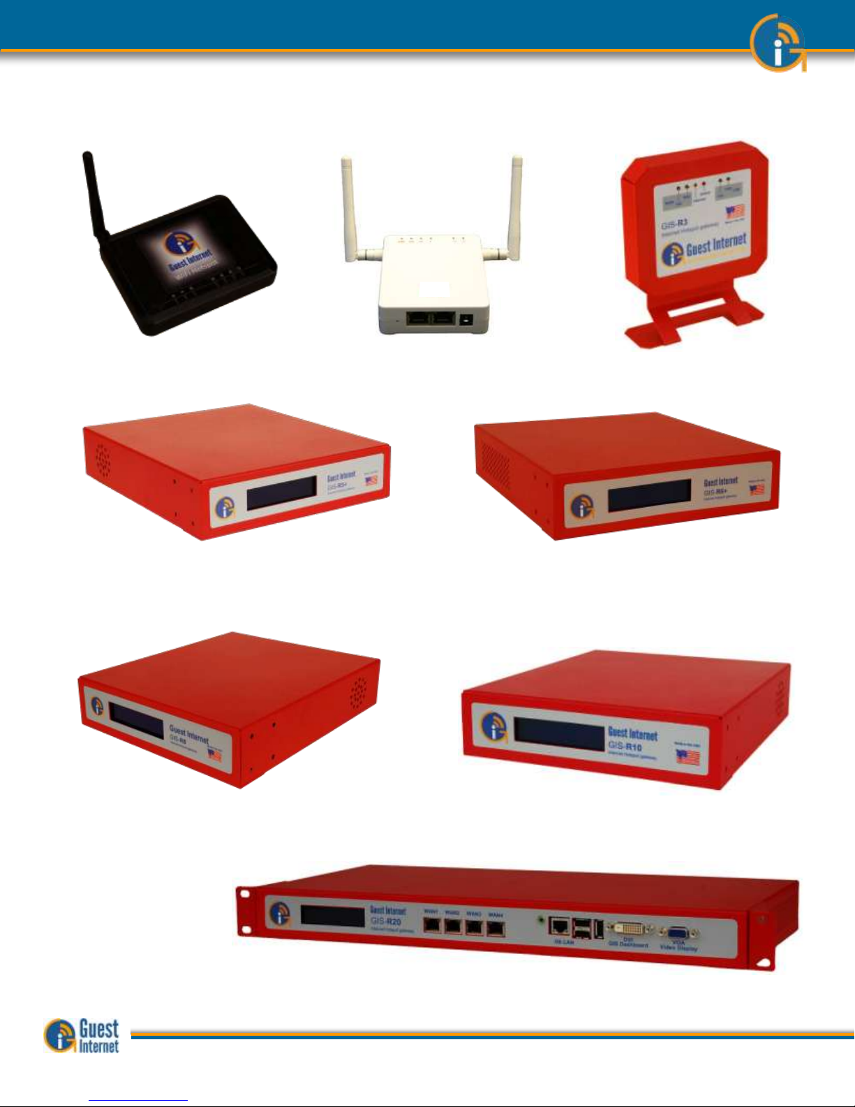
GIS-K1+: Wireless Hotspot gateway
for 25 concurrent users. For bars,
restaurants and any type of public
commercial environment.
GIS-K3: Wireless Hotspot gateway for
50 concurrent users. For bars,
restaurants and any type of public
commercial environment.
GIS-R3: Hotspot gateway for 100
concurrent users. Medium
performance for hotels and motels up to
100 rooms.
GIS-R5+: Hotspot gateway for 150 concurrent users.
Medium performance for hotels and motels up to 150 rooms.
GIS-R6+: Hotspot gateway for 200 concurrent users.
High performance for hotels up to 200 rooms.
GIS-R8: Hotspot gateway for 250 concurrent users.
High performance meets the requirements of hotels that
require greater throughput for up to 250 rooms.
GIS-R10: Hotspot gateway for 250 concurrent users.
High performance meets the requirements of hotels that
require greater throughput with high reliability. Includes dual
WAN load balance with fail-over.
GIS-R20: Hotspot gateway
for 500 concurrent users.
High performance meets the
requirements of large resorts
that require greater throughput
with high reliability. Includes
dual WAN load balance with
fail-over.
Guide to Operation Copyright © Fire4 Systems, Inc., 2013. All Rights Reserved www . guest - internet . com 21
Page 22
6: Characteristics
of the GIS-K1+
Gateway Product
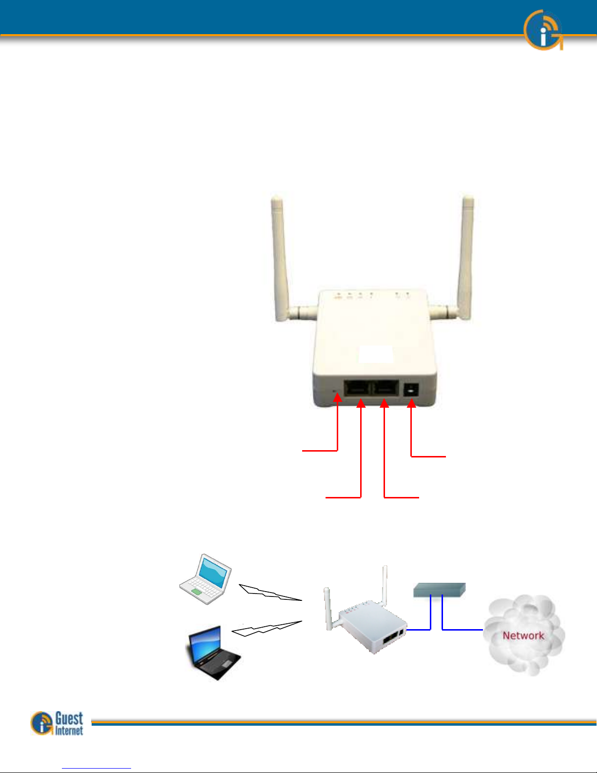
The GIS-K1+ is a wireless hotspot gateway for up to 25 concurrent users; this means that
the unit can have wired computers connected directly to it (Internet kiosks, business center
computers, etc), and can have wireless access points connected to it. Each wireless access
point can provide a wireless, or WiFi connection for laptop computer users who are within
range of the wireless transmission. WiFi enabled devices include notebook computers,
MAC™ computers, iPhones™, iPods™, and Blackberries™. The GIS-K1+ gateway product is
shown below.
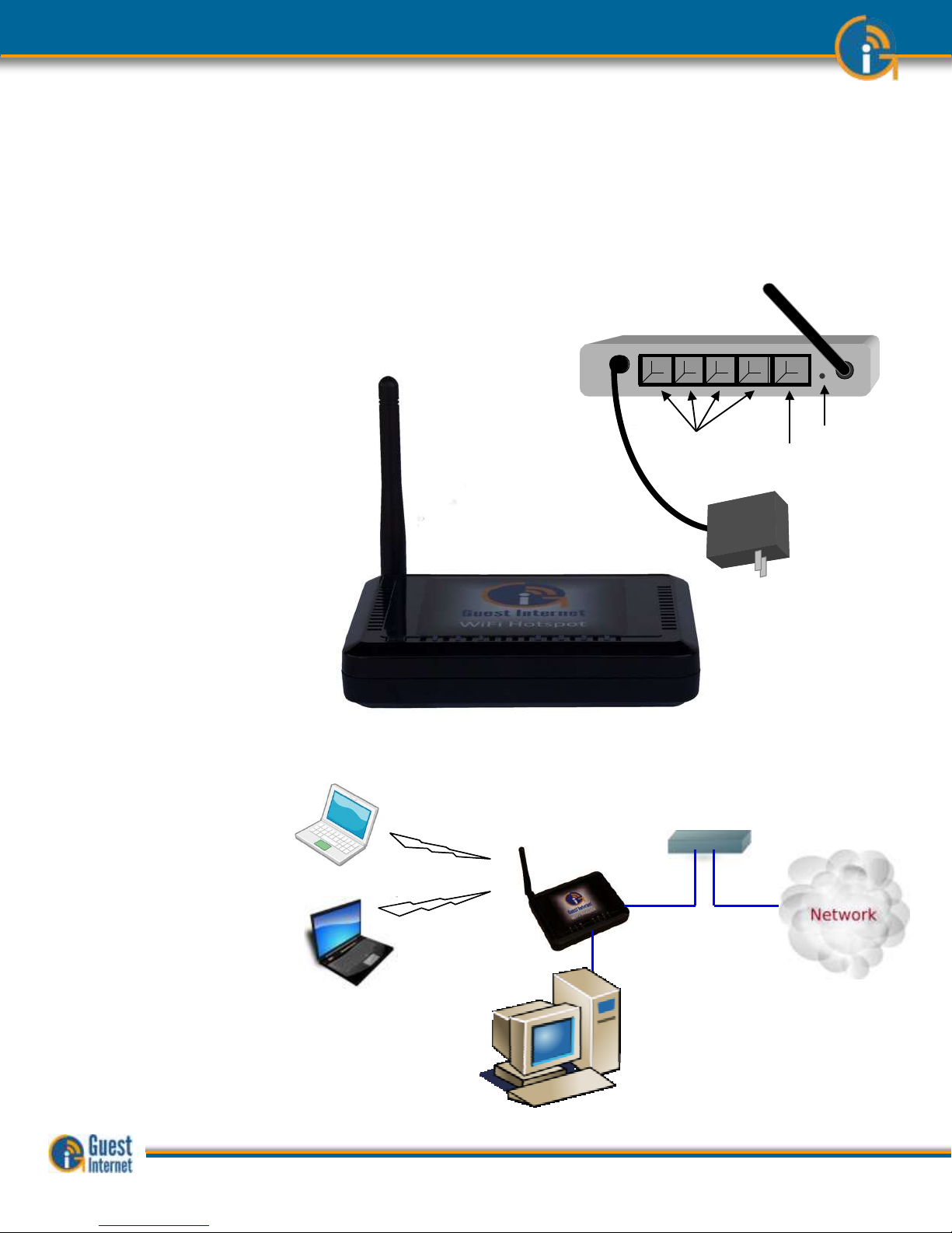
GIS-K1+: The wireless
gateway has five
Ethernet connectors. One
is for the Internet or
WAN, and is connected to
the DSL router. The other
connectors are the LAN
ports. These ports can
have any network device
or computer connected.
The LAN ports can also be
optionally configured to
extend the hotspot
network by adding
wireless access points.
If more LAN ports are
required then a switch
can be connected to one
of the LAN ports.
The GIS-K1+ is shown
with guest laptop
computers connecting
wirelessly and a wired
Internet Kiosk
Internet Connection to
the DSL router
Additional
wireless
access points
Antenna
5 volt power
supply for
110/220volts
Reset
DSL router
GIS-K1+
Wireless Internet
Gateway
Internet
Guest computers
Internet kiosk computer
DSL router
GIS-K1+
Wireless Internet
Gateway
Internet
Guest computers
Internet kiosk computer
Guide to Operation Copyright © Fire4 Systems, Inc., 2013. All Rights Reserved www . guest - internet . com 22
Page 23
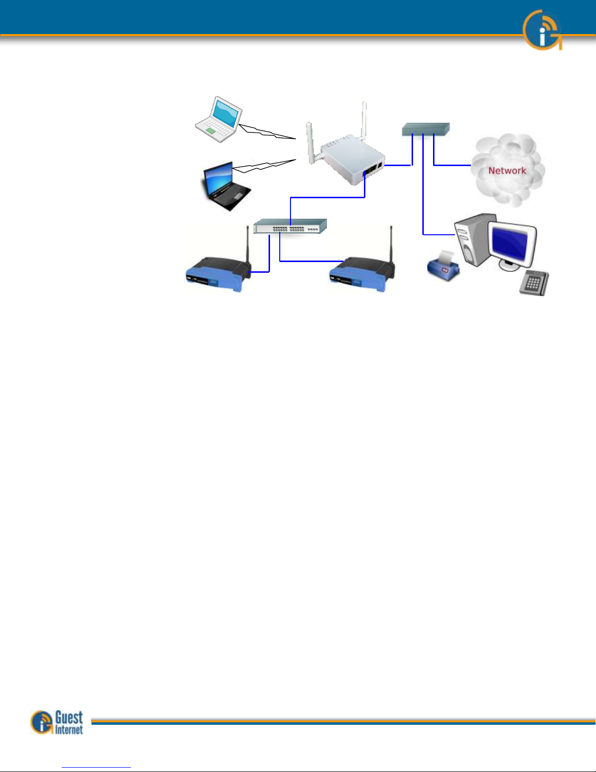
The GIS-K1+ is shown
with the LAN port
configured to extend the
wireless hot spot
network. The LAN port is
firewalled to prevent
public hotspot users
hacking into business
computers that are
connected to the same
DSL/cable circuit
The GIS-K1+ has many of the features of other GIS gateway products, including peer to
peer (Torrent) blocking, however credit card billing is not included. The internal wireless
access point can be expanded by connecting additional wireless access points to the LAN
port via a switch.
The GIS-K1+ applications
Restaurant
Coffee bar
Public library
Truck stop
Motel
RV park
Student dorms
Marina
Fashion show
Bus station
Event reception
Music concert
Theater
Golf club
Casino
Sports club
Gymnasium
Bookstore
Beach kiosk
Shopping mall
Hotel
Resort
Multi-tenant condo
Church
DSL router
GIS-K1+
Wireless Internet
Gateway
Internet
Guest computers
Expansion
wireless
access point
Expansion
wireless access
point
DSL router
GIS-K1+
Wireless Internet
Gateway
Internet
Guest computers
Expansion
wireless
access point
Expansion
wireless access
point
Guide to Operation Copyright © Fire4 Systems, Inc., 2013. All Rights Reserved www . guest - internet . com 23
Page 24
7: Characteristics
of the GIS-K3
Gateway Product
The GIS-K3 is a wireless hotspot gateway for up to 50 concurrent users; this means that
the unit can have wired computers connected directly to it (Internet kiosks, business center
computers, etc), and can have wireless access points connected to it. Each wireless access
point can provide a wireless, or WiFi connection for laptop computer users who are within
range of the wireless transmission. WiFi enabled devices include notebook computers,
MAC™ computers, iPhones™, iPods™, and Blackberries™. The GIS-K3 gateway product is
shown below.
GIS-K3: The wireless
gateway has two
Ethernet connectors. One
is for the Internet or
WAN, and is connected to
the DSL router. The other
connector, called the
LAN, can have any
network device or
computer connected via a
switch.
If more LAN ports are
required then a switch
can be connected to the
LAN port.
The LAN port can also be
optionally configured to
extend the hotspot
network by adding
wireless access points.
The GIS-K3 is shown with
guest laptop computers
connecting wirelessly
24 volt
Power
supply
WAN
connector
LAN
connector
Reset
Switch
24 volt
Power
supply
WAN
connector
LAN
connector
Reset
Switch
DSL router
GIS-K2 Wireless
Internet Gateway
Internet
Guest computers
Guide to Operation Copyright © Fire4 Systems, Inc., 2013. All Rights Reserved www . guest - internet . com 24
Page 25
The GIS-K3 is shown with
the LAN port configured
to extend the wireless
hot spot network. The
LAN port is firewalled to
prevent public hotspot
users hacking into
business computers that
are connected to the
same DSL/cable circuit
The GIS-K3 has all the features of other GIS gateway products, including peer to peer
(Torrent) blocking and credit card billing. The internal wireless access point can be
expanded by connecting additional wireless access points to the LAN port via a switch.
The GIS-K3 applications
Restaurant
Coffee bar
Public library
Truck stop
Motel
RV park
Student dorms
Marina
Fashion show
Bus station
Event reception
Music concert
Theater
Golf club
Casino
Sports club
Gymnasium
Bookstore
Beach kiosk
Shopping mall
Hotel
Resort
Multi-tenant condo
Church
DSL router
Internet
Guest computers
Ticket printer
Credit card
reader
Touch
screen
Point of Sale
(PoS)
computer
GIS-K2 Wireless Internet Gateway
Expansion
wireless
access point
Expansion
wireless
access point
Switch
Guide to Operation Copyright © Fire4 Systems, Inc., 2013. All Rights Reserved www . guest - internet . com 25
Page 26
8: Characteristics
of the GIS-R3
Gateway Product
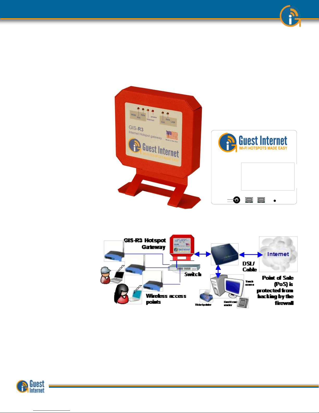
The GIS-R3 is a hotspot gateway for up to 100 concurrent users; this means that the unit
can have wired computers connected directly to it (Internet kiosks, business center
computers, etc), and can have wireless access points connected to it. Each wireless access
point can provide a wireless, or WiFi connection for laptop computer users who are within
range of the wireless transmission. WiFi enabled devices include notebook computers,
MAC™ computers, iPhones™, iPods™, and Blackberries™. The GIS-R4 gateway product is
shown below.
The GIS-R3 gateway has
two Ethernet connectors.
One is labeled Internet
and is connected to the
DSL/cable/T1 router. The
second connector is
labeled LAN. A computer
can be connected to the
LAN ports directly or via a
wireless access point. If
more LAN ports are
required then a switch
can be connected. There
is also a power plug for
the 12 volt connector, and
a reset button to reset the
unit to factory defaults.
The application using the GIS-R3 gateway is shown below.
The GIS-R3 is shown with
wireless access points
connected via a switch to
the LAN port. Business
computers connected to
the same DSL circuit as
the WAN port are
protected from hacking by
the PCI DSS compliant
firewall.
The GIS-R3 applications.
Restaurant
Coffee bar
Public library
Truck stop
Motel
RV park
Public park
Bus station
Trade show
Event reception
Train station
Music concert
Theater
Golf club
Gymnasium
Bookstore
Beach kiosk
Hospital
Airport
Shopping mall
Hotel
Student dorms
Marina
Sports club
Multi-tenant condo
Church
University
Resort
12 volts LAN WAN
reset
Reset to Factory
Defaults:
Hold the reset
button down for
10 seconds
CONNECTORS
GIS-R3 Internet Hotspot gateway
+
-
12 volts LAN WAN
reset
Reset to Factory
Defaults:
Hold the reset
button down for
10 seconds
CONNECTORS
GIS-R3 Internet Hotspot gateway
+
-
Guide to Operation Copyright © Fire4 Systems, Inc., 2013. All Rights Reserved www . guest - internet . com 26
Page 27
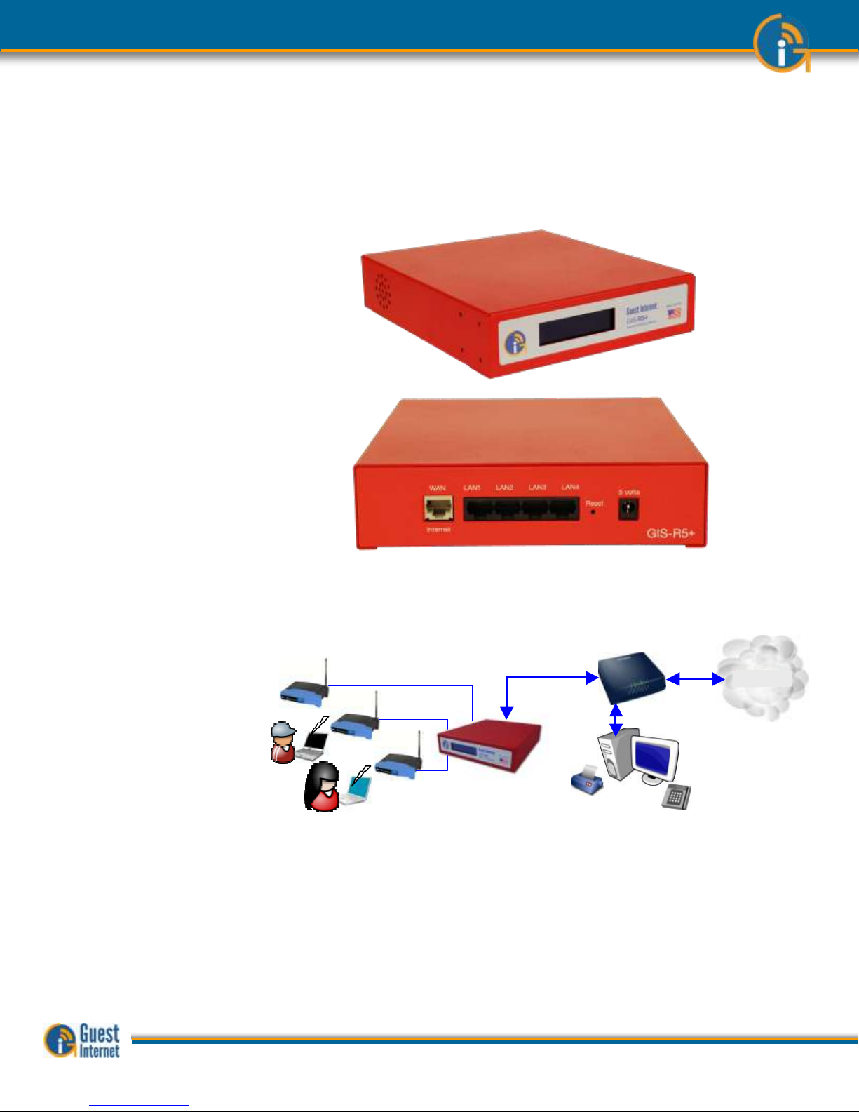
9: Characteristics
of the GIS-R5+
Gateway Product
The GIS-R5+ is a hotspot gateway for up to 150 concurrent users; this means that the
unit can have wired computers connected directly to it (Internet kiosks, business center
computers, etc), and can have wireless access points connected to it. Each wireless access
point can provide a wireless, or WiFi connection for laptop computer users who are within
range of the wireless transmission. WiFi enabled devices include notebook computers,
MAC™ computers, iPhones™, iPods™, and Blackberries™. The GIS-R5+ gateway product
is shown below.
The GIS-R5+ gateway has
five Ethernet connectors.
One is labeled Internet
and WAN and is
connected to the
DSL/cable/T1 router.
Four connectors are
labeled LAN1 to LAN4.
Any network device or
computer can be
connected to these ports.
If more LAN ports are
required then a switch
can be connected.
An application using the GIS-R5+ gateway is shown below.
The GIS-R5+ is shown
with wireless access
points connected the LAN
ports. Business computers
connected to the same
DSL circuit as the WAN
port are protected from
hacking by the PCI DSS
compliant firewall.
The GIS-R5+ applications.
Restaurant
Coffee bar
Public library
Truck stop
Motel
RV park
Public park
Bus station
Trade show
Event reception
Train station
Music concert
Theater
Golf club
Gymnasium
Bookstore
Beach kiosk
Hospital
Airport
Shopping mall
Hotel
Student dorms
Marina
Sports club
Multi-tenant condo
Church
University
Resort
InternetInternet
Ticket printer
Credit card
reader
Touch
screen
Point of Sale
(PoS) is
protected from
hacking by the
GIS-R5 firewall
DSL/
Cable
Wireless access points
GIS-R5+ Hotspot Gateway
Guide to Operation Copyright © Fire4 Systems, Inc., 2013. All Rights Reserved www . guest - internet . com 27
Page 28

10: Characteristics
of the GIS-R6+
Gateway Product
The GIS-R6+ is a hotspot gateway for up to 200 concurrent users; this means that the
unit can have wired computers connected directly to it (Internet kiosks, business center
computers, etc), and can have wireless access points connected to it. Each wireless access
point can provide a wireless, or WiFi connection for laptop computer users who are within
range of the wireless transmission. WiFi enabled devices include notebook computers,
MAC™ computers, iPhones™, iPods™, and Blackberries™. The GIS-R6+ gateway product
is shown below.
The GIS-R6+ gateway has
two Ethernet connectors.
One is labeled Internet
and WAN, and is
connected to the
DSL/cable/T1 router. The
connector labeled LAN is
connected to a computer
via a wired network or
wireless access point. If
more LAN ports are
required then the switch
can be expanded.
An application using the GIS-R6 gateway is shown below.
The GIS-R6+ is shown
with three wireless access
points connected via a
switch to the LAN ports.
Business computers
connected to the same
DSL circuit as the WAN
port are protected from
hacking by the PCI DSS
compliant firewall.
The GIS-R6+ applications.
Restaurant
Coffee bar
Public library
Truck stop
Motel
RV park
Public park
Bus station
Trade show
Event reception
Train station
Music concert
Theater
Golf club
Gymnasium
Bookstore
Beach kiosk
Hospital
Airport
Shopping mall
Hotel
Student dorms
Marina
Sports club
Multi-tenant condo
Church
University
Resort
GIS-R6+
Internet
Kiosk
Switch
Business
center
computer
Wireless Internet
InternetInternet
Ticket printer
Credit card
reader
Touch
screen
Point of Sale
(PoS)
computer is
protected from
hacking by the
firewall
DSL/
Cable
Router
Guide to Operation Copyright © Fire4 Systems, Inc., 2013. All Rights Reserved www . guest - internet . com 28
Page 29
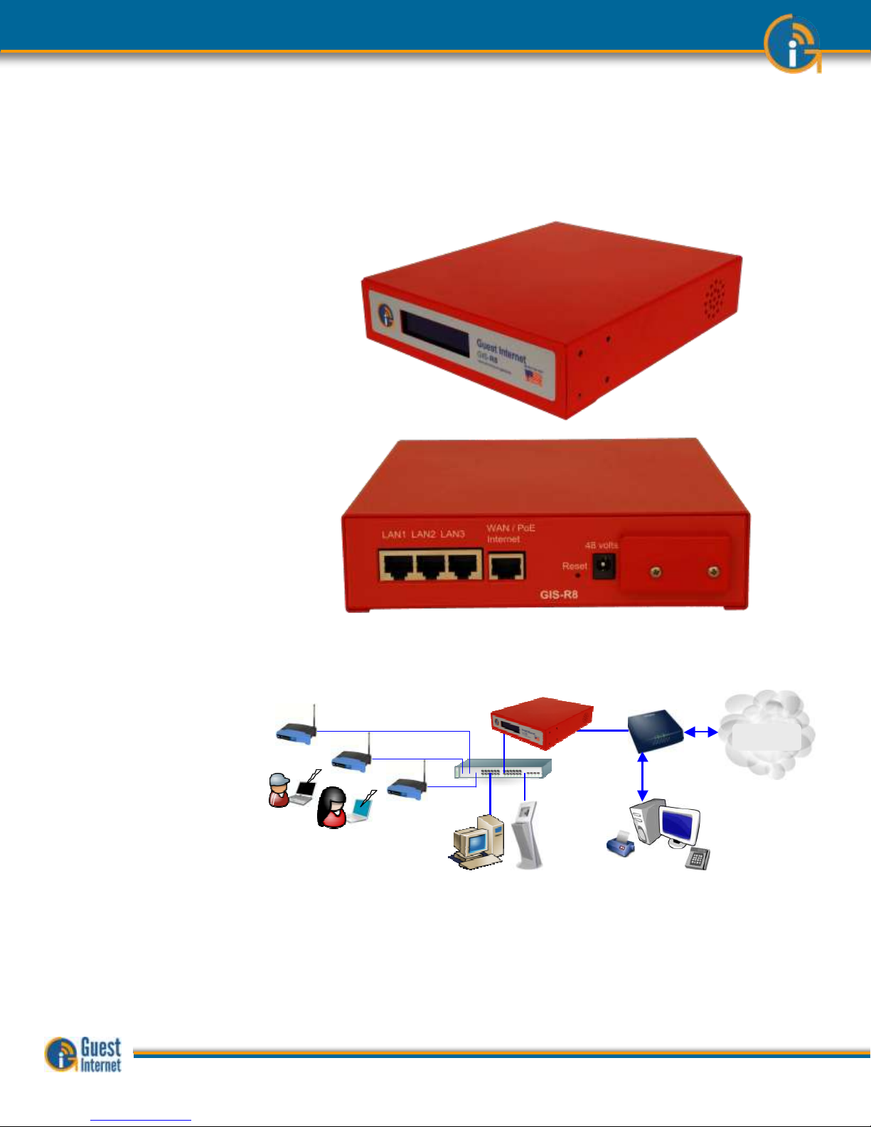
11: Characteristics
of the GIS-R8
Gateway Product
The GIS-R8 is a hotspot gateway for up to 250 concurrent users; this means that the unit
can have wired computers connected directly to it (Internet kiosks, business center
computers, etc), and can have wireless access points connected to it. Each wireless access
point can provide a wireless, or WiFi connection for laptop computer users who are within
range of the wireless transmission. WiFi enabled devices include notebook computers,
MAC™ computers, iPhones™, iPods™, and Blackberries™. The GIS-R10 gateway product is
shown below.
The GIS-R8 gateway has
four Ethernet connectors.
Two are labeled WAN1
and WAN 2 for connection
to two DSL/cable/T1
routers. Two connectors
are labeled LAN1 and
LAN2. Any network device
or computer can be
connected to these ports.
If more LAN ports are
required then a switch
can be connected for a
maximum of 250 ports.
An application using the GIS-R8 gateway is shown below.
The GIS-R8 is shown with
wireless access points, a
business center computer
and a kiosk are connected
to the LAN port via a
switch. Business
computers connected to
the same DSL circuit as
the WAN port are
protected from hacking by
the PCI DSS compliant
firewall.
GIS-R8 applications.
Restaurant
Coffee bar
Public library
Truck stop
Motel
RV park
Public park
Bus station
Trade show
Event reception
Train station
Music concert
Theater
Golf club
Gymnasium
Bookstore
Beach kiosk
Hospital
Airport
Shopping mall
Hotel
Student dorms
Marina
Sports club
Multi-tenant condo
Church
University
Resort
GIS-R8
Internet
Kiosk
Switch
Business
center
computer
Wireless Internet
InternetInternet
Ticket printer
Credit card
reader
Touch
screen
Point of Sale
(PoS)
computer is
protected from
hacking by the
firewall
DSL/
Cable
Router
Guide to Operation Copyright © Fire4 Systems, Inc., 2013. All Rights Reserved www . guest - internet . com 29
Page 30
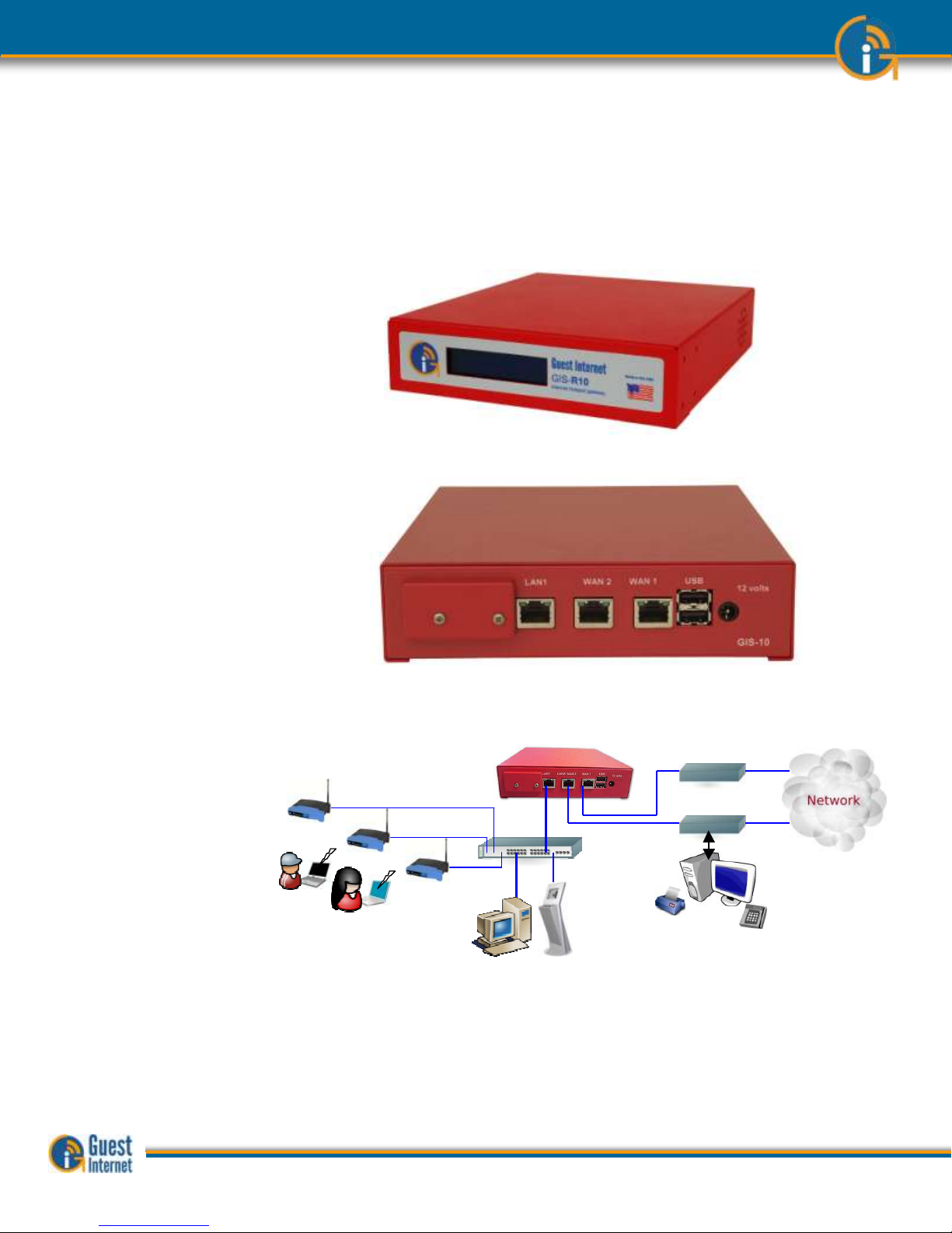
12: Characteristics
of the GIS-R10
Gateway Product
The GIS-R10 is a hotspot gateway for up to 250 concurrent users; this means that the unit
can have wired computers connected directly to it (Internet kiosks, business center
computers, etc), and can have wireless access points connected to it. Each wireless access
point can provide a wireless, or WiFi connection for laptop computer users who are within
range of the wireless transmission. WiFi enabled devices include notebook computers,
MAC™ computers, iPhones™, iPods™, and Blackberries™. The GIS-R10 gateway product is
shown below.
The GIS-R10 gateway has
three Ethernet
connectors. Two are
labeled WAN1 and WAN 2
for connection to two
DSL/cable/T1 routers.
The connector labeled
LAN1 can have computer
can be connected directly
or via a wireless access
point. If more LAN ports
are required then a switch
can be connected for a
maximum of 250 ports.
An application using the GIS-R10 gateway is shown below.
The GIS-R10 is shown
with two wireless access
points connected to the
LAN port via a switch. The
two WAN ports are DSL
and Cable circuits.
Business computers
connected to the same
DSL circuit as the WAN
ports are protected from
hacking by the PCI DSS
compliant firewall.
GIS-R10 applications.
Restaurant
Coffee bar
Public library
Truck stop
Motel
RV park
Public park
Bus station
Trade show
Event reception
Train station
Music concert
Theater
Golf club
Gymnasium
Bookstore
Beach kiosk
Hospital
Airport
Shopping mall
Hotel
Student dorms
Marina
Sports club
Multi-tenant condo
Church
University
Resort
GIS-R10
Internet
Internet
Kiosk
Switch
DSL/T1 circuit
DSL/T1 circuit
Dual WAN load balance with fail-over
Two isolated virtual gateways
Ticket printer
Credit card
reader
Touch
screen
Point of Sale (PoS)
computer is protected
from hacking by the
firewall
Business
center
computer
Wireless Internet
GIS-R10
Internet
Internet
Kiosk
Switch
DSL/T1 circuit
DSL/T1 circuit
Dual WAN load balance with fail-over
Two isolated virtual gateways
Ticket printer
Credit card
reader
Touch
screen
Point of Sale (PoS)
computer is protected
from hacking by the
firewall
Business
center
computer
Wireless Internet
Guide to Operation Copyright © Fire4 Systems, Inc., 2013. All Rights Reserved www . guest - internet . com 30
Page 31

13: Characteristics
of the GIS-R20
Gateway Product
The GIS-R20 is a hotspot gateway for up to 500 concurrent users; this means that the unit
can have wired computers connected directly to it (Internet kiosks, business center
computers, etc), and can have wireless access points connected to it. Each wireless access
point can provide a wireless, or WiFi connection for laptop computer users who are within
range of the wireless transmission. WiFi enabled devices include notebook computers,
MAC™ computers, iPhones™, iPods™, and Blackberries™. The GIS-R16 gateway product is
shown below.
The GIS-R20 gateway has
five Ethernet connectors.
Two ports are configured
for WAN connections.
Three ports are
configured for LAN
connections. Any network
device or computer can be
connected to the LAN
ports. If more LAN ports
are required then a switch
can be connected.
An application using the GIS-R20 gateway is shown below.
The GIS-R20 is shown
with wireless access
points and Internet kiosks
connected via a switch to
one of the LAN ports. The
two WAN ports provide
load balancing and failover for redundant
operation. Business
computers connected to
the same DSL circuit as
the WAN ports are
protected from hacking by
the PCI DSS compliant
firewall.
The GIS-R20 applications.
Public library
Motel
RV park
Public park
Trade show
Music concert
Theater
Golf club
Hospital
Airport
Shopping mall
Hotel
Student dorms
Multi-tenant condo
University
Resort
WAN1
WAN2
LAN1
LAN2
LAN3
GIS-R20
Internet
Wireless
Internet
Internet
Kiosks
DSL/T1 circuit
DSL/T1 circuit
Dual WAN
Load balance
With fail-over
TRADE SHOW
NETWORK EXAMPLE
Guide to Operation Copyright © Fire4 Systems, Inc., 2013. All Rights Reserved www . guest - internet . com 31
Page 32

14: Characteristics
of the GIS-TP1
ticket printer
Product
Many Internet WiFi Hotspots are configured so that the user has to type an access code to
be connected to the Internet. This procedure prevents unauthorized users from getting
Internet access. Guest Internet gateways have a page to generate access codes which can
be downloaded to a spreadsheet and printed on labels. GIS gateways also have an
application program interface (API) that allows point of sale (PoS) systems to request an
access code and print the code on the PoS ticket printer. The GIS-TP1 provides an
alternative to print access codes on demand when the user requests a code. This greatly
simplifies the management of access codes as it is no longer necessary to generate a large
number of codes and then print codes using a computer. A hotel reception desk or
concierge can now print access codes for guests. A coffee bar can print access codes for
guests when purchases are made. Codes are printed using the touch screen of a tablet
computer. This can be a low cost Android tablet with a 7inch display screen, or an Apple
iPad tablet. Ten access codes can be pre-configured and appear as buttons on the screen
of the tablet computer.
Like all Guest Internet gateway products, the ticket printer is very easy to install and
operate. The ticket printer should be connected to a LAN port of the GIS gateway using a
switch. Wireless access points will also be connected to the GIS gateway using the same
switch. Next, the ticket printer is configured using the GIS administrator page to select up
to ten access code durations as ticket options. A new login password is also created for the
tablet computer login. Finally, the tablet computer wireless should be connected to the GIS
gateway via the wireless access point. Open the browser and use the ticket printer login.
The ticket select buttons are then displayed on the screen.
GIS-TP1 access code
ticket printer
The GIS-TP1 ticket printer uses 58mm thermal paper that can be obtained from any office
supplies store. 58mm thermal paper is used by point of sale thermal printers.
The GIS-TP1 ticket printer has an Ethernet connection that must be connected to a LAN
port of the gateway, either directly of via a switch. The GIS-TP1 cannot be connected to
the WAN port of the gateway.
The GIS-TP1 is connected to the gateway as shown in the figure below. A separate tablet
computer is required to control ticket printing.
Guide to Operation Copyright © Fire4 Systems, Inc., 2013. All Rights Reserved www . guest - internet . com 32
Page 33

GIS-TP1 network
connection
The power and data connections
of the GIS-TP1 are underneath the
unit to the rear.
Use only the 12 volt, 3 amp power
supply provided with the unit.
A power on/off switch is located at
the rear of the printer.
The GIS-TP1 is shipped with the
following accessories
- Power supply, 12 volts
- Ethernet cable
- Quick start guide
Power Ethernet
Guide to Operation Copyright © Fire4 Systems, Inc., 2013. All Rights Reserved www . guest - internet . com 33
Page 34

15: Discontinued
products:
Evolution of technology is extremely rapid for any type of computer or network product.
Gordon Moore of Intel is famous for stating that processing power will double every 18
months (Moore’s Law). GIS products also follow the rules of Moore’s Law and evolve at the
same speed as the computing industry.
Some members of the current product range replace older products. New products are
faster, handle a greater throughput and have more features than the products that they
replace. Even though products are discontinued we continue to provide firmware upgrades
after the manufacture of the product has ceased. Discontinued products are listed below.
GIS-K1: replaced by the GIS-K2, more users, more features
GIS-R2: discontinued
GIS-R4: replaced by the GIS-R3, faster, more features, lower cost
GIS-R5: replaced by the GIS-R5+, more features, lower cost
GIS-R6: replaced by the GIS-R6+, faster, more features
GIS-R16: replaced by the GIS-R20, faster, more features
Information about the discontinued product is listed on the following pages.
The GIS-R2 unit
The GIS-R2 is a hotspot gateway for up to 50 concurrent users. The GIS-R2 gateway
product is shown below.
The GIS-R2 gateway has five
Ethernet connectors. One is
labeled Internet and is
connected to the
DSL/cable/T1 router. Four
connectors are labeled LAN1
to LAN4. Any network device
or computer can be
connected to these ports. If
more LAN ports are required
then a switch can be
connected for a maximum of
250 ports.
power
LAN4 LAN3 LAN2 LAN1 Internet
Connection to the DSL
router for Internet access
Connection to switches, computers
and wireless access points
power
LAN4 LAN3 LAN2 LAN1 Internet
power
LAN4 LAN3 LAN2 LAN1 Internet
Connection to the DSL
router for Internet access
Connection to switches, computers
and wireless access points
Connection to the DSL
router for Internet access
Connection to switches, computers
and wireless access points
Guide to Operation Copyright © Fire4 Systems, Inc., 2013. All Rights Reserved www . guest - internet . com 34
Page 35

The GIS-R4 unit
The GIS-R4 is a hotspot gateway for up to 100 concurrent users. The GIS-R4 gateway
product is shown below.
The GIS-R4 gateway has five
Ethernet connectors. One is
labeled Internet and is
connected to the
DSL/cable/T1 router. Four
connectors are labeled LAN1
to LAN4. Any network device
or computer can be
connected to these ports. If
more LAN ports are required
then a switch can be
connected for a maximum of
250 ports.
The GIS-R5 unit
The GIS-R5 is a hotspot gateway for up to 150 concurrent users. The GIS-R5 gateway
product is shown below.
The GIS-R5 gateway has
three Ethernet connectors.
One is labeled Internet and is
connected to the
DSL/cable/T1 router. Two
connectors are labeled LAN1
and LAN2. Any network
device or computer can be
connected to these ports. If
more LAN ports are required
then a switch can be
connected for a maximum of
250 ports.
Internet /PoELAN1
Reset
GIS-R5
LAN2 12 volts
Connection to the DSL router for Internet
access Powered via PoE
Connection to switches, computers and
wireless access points
Internet /PoELAN1
Reset
GIS-R5
LAN2 12 volts
Connection to the DSL router for Internet
access Powered via PoE
Connection to switches, computers and
wireless access points
power
LAN4 LAN3 LAN2 LAN1 Internet
Connection to the DSL
router for Internet access
Connection to switches, computers
and wireless access points
power
LAN4 LAN3 LAN2 LAN1 Internet
power
LAN4 LAN3 LAN2 LAN1 Internet
Connection to the DSL
router for Internet access
Connection to switches, computers
and wireless access points
Connection to the DSL
router for Internet access
Connection to switches, computers
and wireless access points
Guide to Operation Copyright © Fire4 Systems, Inc., 2013. All Rights Reserved www . guest - internet . com 35
Page 36

The GIS-R6 unit
The GIS-R6 is a hotspot gateway for up to 200 concurrent users. The GIS-R6 gateway
product is shown below.
The GIS-R6 gateway has
three Ethernet connectors.
One is labeled Internet and is
connected to the
DSL/cable/T1 router. Two
connectors are labeled LAN1
and LAN2. Any network
device or computer can be
connected to these ports. If
more LAN ports are required
then a switch can be
connected.
The GIS-R16 unit
The GIS-R16 is a hotspot gateway for up to 500 concurrent users The GIS-R16 gateway
product is shown below.
The GIS-R16 gateway has six
Ethernet connectors. One is
labeled ‘6’ and is connected
to the DSL/cable/T1 router.
Five connectors are labeled
‘1’ to ‘5’. Any network device
or computer can be
connected to these ports. If
more LAN ports are required
then a switch can be
connected.
Internet /PoELAN1
Reset
GIS-R6
LAN2 12 volts
Connection to the DSL router for Internet
access Powered via PoE
Connection to switches, computers and
wireless access points
Internet /PoELAN1
Reset
GIS-R6
LAN2 12 voltsInternet /PoELAN1
Reset
GIS-R6
LAN2 12 volts
Connection to the DSL router for Internet
access Powered via PoE
Connection to switches, computers and
wireless access points
Connection to the
DSL/cable/T1/T2 router for
Internet access
Connection to switches, computers
and wireless access points
Connection to the
DSL/cable/T1/T2 router for
Internet access
Connection to switches, computers
and wireless access points
Guide to Operation Copyright © Fire4 Systems, Inc., 2013. All Rights Reserved www . guest - internet . com 36
Page 37

16: Installation of
Guest Internet
Gateway Products
Guest Internet gateway products can be used to manage public Internet for many different
applications.
The following table shows how GIS gateway products are used for different applications.
Product
Application
Type of access
Additional Equipment
GIS-K3
Restaurant Internet access for up to 50 concurrent
users
Wireless Hotspot
DSL or cable Internet service
GIS-R10
Hotel rooms with a wired Internet connection for up
to 250 concurrent users
Wired cat-5 connection
Multi-port switch, DSL or cable
Internet service with dual backhaul
for load balance and redundancy
GIS-R3
Hotel lobby wireless Internet for up to 100
concurrent users
Wireless Hotspot
One or two wireless access points,
DSL or cable Internet service
GIS-R3
Golf course wireless Internet for up to 100
concurrent users. One central antenna can provide
service for receivers (e.g. WiFi Boost) on golf carts.
Wireless Hotspot
High power outdoor access point
(Ubiquity Bullet 2HP or Rocket),
DSL or cable Internet service
GIS-R5+
Conference hall for up to 150 concurrent users
Wireless Hotspot
Two wireless access points, DSL or
cable Internet service
GIS-R3
Hotel business center with four computers
Kiosk service
DSL or cable Internet service
GIS-R20
Provide wireless Internet for an outdoor concert
using several high power wireless access points for
500 users
Wireless Hotspot
T3 or fiber Internet service
GIS-K1+
Provide wireless Internet for a coffee bar with a
single wireless hotspot
Wireless Hotspot
DSL or cable Internet service
GIS-R20
Provide wireless Internet for a trade show with
many wireless access points
Wireless Hotspot
T3 or fiber Internet service
GIS-R6+
Provide wireless Internet for airports and train
stations using a large number of wireless access
points
Wireless Hotspot
T3 or fiber Internet service
GIS-R3
Provide wireless Internet for an RV park using
several outdoor long range wireless access points
Wireless Hotspot
DSL or cable Internet service
GIS-R8
Provide wireless Internet for a 300 berth marina by
connecting several outdoor long range wireless
access points
Wireless Hotspot
DSL or cable Internet service
GIS-R3
Provide wireless Internet for a resort using several
indoor and outdoor wireless access points
Wireless Hotspot
DSL or cable Internet service
GIS-R5+
Provide Internet for a flea market
Wireless Hotspot
DSL or cable Internet service
GIS-K1+
Provide wireless Internet for a gas station
Wireless Hotspot
DSL or cable Internet service
Guide to Operation Copyright © Fire4 Systems, Inc., 2013. All Rights Reserved www . guest - internet . com 37
Page 38

17: Powering the
Gateway Products
This section describes the power supply units that Guest Internet gateway products are
shipped with.
Each product requires a specific power supply voltage as shown in the figures below. Each
power supply plugs into the power connector shown on the product photos below. The
power supply can be used with either 110 volts or 220 volts. Connecting a power supply
with the wrong voltage will damage the gateway.
GIS-K1+ power supply
and power connector
5 volt power supply
Use only the power supply
provided to avoid damage
GIS-K3 power supply and
power connector
24 volt power supply
Use only the power supply
provided to avoid damage
GIS-R3 power supply and
connections
12 volt power supply
Use only the power supply
provided to avoid damage
Power supply
for
110/220volts
12 volts
5 volt power supply
For 110/220volts
5 volt power supply
For 110/220volts
Guide to Operation Copyright © Fire4 Systems, Inc., 2013. All Rights Reserved www . guest - internet . com 38
Page 39

GIS-R5+ power supply
and connections
5 volt power supply
Use only the power supply
provided to avoid damage
GIS-R6+ power supply
and connections
24 volt power supply
Use only the power supply
provided to avoid damage
GIS-R8 power supply and
connections
48 volt power supply
Use only the power supply
provided to avoid damage
Power supply
for
110/220volts
5 volts
Power supply
for
110/220volts
24 volts
Power supply
for
110/220volts
48 volts
Guide to Operation Copyright © Fire4 Systems, Inc., 2013. All Rights Reserved www . guest - internet . com 39
Page 40

GIS-R10 power supply
and connections
12 volt power supply
Use only the power supply
provided to avoid damage
GIS-R20 power connector
12 volt supply
4-pin power connector
12 volts, 3amps
Use only the power supply
provided to avoid damage
GIS-TP1 power connector
12 volt supply
12 volts, 3amps
Use only the power supply
provided to avoid damage
Connect the Ethernet data
cable as shown
Power supply
for
110/220volts
12 volts
12 volts
3 amps
Power supply
for
110/220volts
Power Ethernet
Guide to Operation Copyright © Fire4 Systems, Inc., 2013. All Rights Reserved www . guest - internet . com 40
Page 41

18: Switching the
Gateway Product
on for the First
Time
The GIS-gateway must be configured before it can be used. The product has a very easy to
use Wizard which speeds through the configuration process. Configuration takes around
five minutes.
The GIS-gateway must be connected as shown in the diagram at the bottom of this page.
The INTERNET port must be connected to the Internet via the DSL router. The GISgateway cannot be configured without Internet access. The computer Ethernet cable is
connected to any LAN port
When the GIS-gateway is connected as shown in the diagram the power supply should be
connected. Check the power on LED is lit on the front of the enclosure, or the LCD display
is lit on some models. The WAN link LED indicates that the Internet port is connected to
the DSL router, on models with the LCD display a message indicated this connection.
Next switch on the computer. When the computer has booted up then open the browser.
If the browser gives a message that the Internet is not available then check the Ethernet
cable and connectors between the GIS-gateway LAN port and the computers Ethernet
connector.
Connect your computer to
the gateway product LAN
port
The GIS-K2 must be connected as shown in the diagram on the following page. The GIS-K2
INTERNET port must be connected to the Internet via the DSL/Cable/T1 router. The GISK2 cannot be configured without Internet access. The computer wireless network interface
is connected to network name:
Hotspot
When the GIS-K2 is connected as shown in the diagram the power supply should be
connected. Check power on LED is lit above the enclosure. A LED indicates power is
connected and a LED indicates that the Internet port is connected to the DSL router.
Next open the computer browser. If the browser gives a message that the Internet is not
available then check the wireless connection between the GIS-K2 and the computer.
Guide to Operation Copyright © Fire4 Systems, Inc., 2013. All Rights Reserved www . guest - internet . com 41
Page 42

Connect your computer
using the wireless
interface. Look for the
network name (SSID):
Hotspot and connect
With the Guest Internet gateway connected as shown, proceed to the Wizard configuration
process.
DSL
GIS-K2
Internet
Configuration
computer with
wireless
Connect to:
Hotspot
GIS-K2 Login
Page
Internet port
Guide to Operation Copyright © Fire4 Systems, Inc., 2013. All Rights Reserved www . guest - internet . com 42
Page 43

19: Installing the
Gateway Product
in a Computer
Network
When the GIS-gateway has been configured it can be installed in the business network.
Configuration changes may be necessary for the GIS-gateway to provide all the desired
features required for the business network.
Several different network configurations are possible when installing the GIS- gateway. It is
important to recognize that restrictions are placed on the network design if the network
has any computer point-of-sale terminal that is used to process credit card information.
The Payment Card Industry Data Security Standard (PCI DSS) requires all
businesses to ensure that credit card information is protected, by preventing unauthorized
access via the network, using one or more firewall products.
Network designs have two points of entry for hackers who try to steal credit card
information from point of sale computers. The first point of entry is through the Internet
connection. The outbound Internet connection is required to process credit card
information. However the inbound direction has to be blocked to prevent hackers using the
internet to access the point of sale computers.
The second point of entry is through any wireless access point that is provided for guests
and visitors to get Internet access. The PCI DSS standards recommend that two separate
Internet circuits should be used: one for the point of sale system, and one for the public
guest Internet network.
One Internet circuit can be used when firewall devices are installed to protect the point of
sale system from attack. A firewall however is only as good as the person who configures
the firewall. It is necessary to take great care when writing the firewall rules to ensure that
no path exists for a possible attacker.
PCI DSS compliant network configurations are shown in the following figures. Additional
information about PCI DSS recommendations can be found at this URL.
https://www.pcisecuritystandards.org/security_standards/pci_dss_download_
agreement.html
The gateway connected
to a DSL router to provide
Internet access for
guests
The next figure shows the GIS-gateway connected to a business network that has an
Internet connection via DSL or T1. The GIS-gateway firewall blocks access of public
network DMZ (de-militarized zone) users to the business network computers for PCI DSS
compliance.
GIS-R6+
Internet
Kiosk
Switch
Business
center
computer
Wireless Internet
InternetInternet
Ticket printer
Credit card
reader
Touch
screen
Point of Sale
(PoS)
computer is
protected from
hacking by the
firewall
DSL/
Cable
Router
Guide to Operation Copyright © Fire4 Systems, Inc., 2013. All Rights Reserved www . guest - internet . com 43
Page 44

The next figure shows a business network with full PCI-DSS compliance: a single firewall
isolates the business network and public network (DMZ). With this configuration it is
possible for one of the business computers to generate and manage access codes using the
GIS-gateway providing that the computer has been authorized to do so within the firewall.
DSL/T1
circuit
Internet
Public user access is blocked to the business
network that includes a point of sale terminal
Set private IP range 192.168.xx.xx or 10.xx.xx.xx
to prevent access from the public network
Public network (DMZ): wireless
hotspot, kiosks, business center
PoS
Inventory
Gateway Firewall
Switch
GIS-R6+
Internet
Kiosk
Switch
Business
center
computer
Wireless Internet
DSL/T1
circuit
Internet
Public network (DMZ): The gateway
cannot be accessed from a business
network computer
PoS
Inventory
Gateway Connected via a Firewall
Switch
Firewall: isolates the public and private
networks. Protects the private network
from attack via the Internet
GIS-R6+
Internet
Kiosk
Switch
Business
center
computer
Wireless Internet
Guide to Operation Copyright © Fire4 Systems, Inc., 2013. All Rights Reserved www . guest - internet . com 44
Page 45

The GIS K1+/K3 wireless gateway devices are configured differently to the GIS-R-series
gateway devices. Configuration changes may be necessary for the GIS-K1+/K3 to provide
all the desired features required for the business network.
Several different network configurations are possible when installing the GIS-K1+/K3. It is
important to recognize that restrictions are placed on the network design if the network
has any computer point-of-sale terminal that is used to process credit card information.
The Payment Card Industry Data Security Standard (PCI DSS) requires all
businesses to ensure that credit card information is protected, by preventing unauthorized
access via the network, using one or more firewall products.
Network designs have two points of entry for hackers who try to steal credit card
information from point of sale computers. The first point of entry is through the Internet
connection. The outbound Internet connection is required to process credit card
information. However the inbound direction has to be blocked to prevent hackers using the
internet to access the point of sale computers.
The second point of entry is through any wireless access point that is provided for guests
and visitors to get Internet access. The PCI DSS standards recommend that two separate
Internet circuits should be used: one for the point of sale system, and on for the public
guest Internet network.
One Internet circuit can be used when firewall devices are installed to protect the point of
sale system from attack. A firewall however is only as good as the person who configures
the firewall. It is necessary to take great care when writing the firewall rules to ensure that
no path exists for a possible attacker.
PCI DSS compliant network configurations are shown in the following figures. Additional
information about PCI DSS recommendations can be found at this URL.
https://www.pcisecuritystandards.org/security_standards/pci_dss_download_
agreement.html
The GIS-K1+ connected
to a DSL router to provide
Internet access for
guests. The business
computer (PoS) is
protected from the public
Internet users by a
firewall in the GIS-K1+
All GIS hotspot gateway products have identical PCI DSS compliant firewalls.
DSL router
GIS-K1+ Wireless
Internet Gateway
Internet
Guest computers
Ticket printer
Credit card
reader
Touch
screen
The Point of Sale (PoS) computer is protected from public access by a firewall in the GIS-K1
Guide to Operation Copyright © Fire4 Systems, Inc., 2013. All Rights Reserved www . guest - internet . com 45
Page 46

20: Connecting
Your Computer
Browser to the
Guest Internet
Product
When your computer is connected to the GIS-gateway (previous section) then you
can start the configuration and set up process using your computer browser. The
set up process can be done with any type of browser.
When a browser opens it is usually directed to go to the home page. This is the page you
always see when the browser opens.
When you open your browser your home page will change, instead of your usual home
page you will see the Guest Internet setup wizard.
If you did not have a home page set in your browser you should type the following into the
URL address line.
http://aplogin.com
The setup wizard will appear only the first time you power up the device. When the Guest
Internet product has been configured then the configuration wizard is no longer shown. It
is replaced by a login page, which was generated by the setup wizard.
When the browser
window openes it will go
to the home page URL
If the Setup Wizard is not
displayed then type in the
URL shown sbove.
Type in the URL
http://aplogin.com
Guide to Operation Copyright © Fire4 Systems, Inc., 2013. All Rights Reserved www . guest - internet . com 46
Page 47

21: The Quick
Start Wizard: Get
Your Gateway
Working Quickly
The first time that you connect to your Guest Internet gateway product you should see the
page shown below displayed in your Internet browser window.
The screen shows that there are five steps to complete the setup process. Each step is a
page that requires some information to be typed in or an option selected.
Please read through this manual first before setting up your Guest Internet product.
The purpose of the setup wizard is twofold
(a) Verify that the gateway is connecting to the Internet
(b) Configure the login page that your guests will see when they try to connect to the
Internet
During the wizard set up process you will be requested to enter information about your
business that will be shown to guests on the login page. It is always good to present your
website address, email address and telephone number for guests to note or save on their
computers. All information is optional: if you don’t type it in it will not be shown on the
login screen.
In addition to your business information you can also type in an advertising message. The
message could tell guests about a special offer, or provide information essential for guests.
You can also log in at any time to change the advertising message.
Guide to Operation Copyright © Fire4 Systems, Inc., 2013. All Rights Reserved www . guest - internet . com 47
Page 48

22: The Quick
Start Wizard:
Check the
Internet
Connection
The TEST INTERNET ACCESS setup page verifies that your Guest Internet gateway product
is connected to the Internet. The setup process cannot be completed unless the product is
connected to the Internet.
Look on the top right hand corner of the browser window. You will see a green YES or a
red NO. If you have a green YES then your product is connected to the Internet and you
can proceed to the next page by clicking on the button ‘Continue to Step 2’.
If you see a red NO then you have a connection problem.
First verify that your DSL modem provides a good Internet connection by connecting a
computer to the DSL modem using an Ethernet cable.
Verify that the Guest Internet product is connected to the DSL router (check that the blue
LED is lit) and then click on ‘click to test the internet connection’.
If the Internet status still shows a red NO then click on ‘click to correct this problem’.
Verify that your DSL modem is a ‘DHCP server’. You may need help from an IT or network
person to answer this question. Click on the link ‘click to attempt an IP address’ shown on
the following page.
You may have a shared T1 service in which case you will have to configure your Guest
Internet product with a ‘fixed IP address’. You can click on Advanced Settings and then
click on Network Interfaces to set a fixed IP address. This procedure is explained later in
this manual. Your T1 service provider will tell you what IP address should be configured.
Guide to Operation Copyright © Fire4 Systems, Inc., 2013. All Rights Reserved www . guest - internet . com 48
Page 49

If you still have a red NO after trying the steps described above then you will have to call a
network specialist to help you. You can contact a network specialist by calling local IT
companies. You may also find a network specialist by calling your high speed Internet
service provider.
It is likely that your DSL router or cable modem has a firewall that is preventing the GISgateway connecting to the Internet. You should look at your DSL router configuration to
‘enable NAT’ing devices’.
Unfortunately our support line cannot help you with this problem because an on-site
inspection is required. The network specialist will visit your premises to diagnose and
correct the problem.
Configuration of the Hotspot gateway cannot be completed until a connection to the
Internet is obtained. Connect the gateway to an alternative DSL or cable service to
complete the configuration process.
Guide to Operation Copyright © Fire4 Systems, Inc., 2013. All Rights Reserved www . guest - internet . com 49
Page 50

23: The Quick
Start Wizard: Set
the Time Zone and
Password
When your Guest Internet product has a good connection to the Internet and you have
clicked on the link to proceed to page 2, then you will see the page shown below.
The GIS-gateway synchronizes with Internet time and date to time access codes and
provide the data and time for the usage log. It is necessary to first select the time zone for
the gateway. Click on the arrow at the right of the box to see the drop down menu. Select
your time zone from this list. The default time zone is US eastern time.
The GIS-gateway has no default administrator password. The administrator access
password must be entered in the box. Guest Internet products can only be operated when
a unique password has been entered, following the recommendations of the Payment Card
Industry Data Security Standard (PCI - DSS). Create a ‘strong’ password using the following
rules:
The password should be at least 8 characters
Don’t use words that are in the dictionary
Include capital letters, numbers and punctuation marks in the password
The GIS-K2 wireless gateway has an additional box to set the hotspot name (SSID) that is
broadcast wirelessly. The default name is HOT SPOT. A name should be selected that can
be recognized by users (e.g. Coffee Bar Hotspot).
See the screen on the following page.
Guide to Operation Copyright © Fire4 Systems, Inc., 2013. All Rights Reserved www . guest - internet . com 50
Page 51

When you have completed this screen click on the button to proceed to step 3.
Guide to Operation Copyright © Fire4 Systems, Inc., 2013. All Rights Reserved www . guest - internet . com 51
Page 52

24: The Quick
Start Wizard:
Enter Your
Business
Information for
the Login Page
The next step in the setup process is the creation of the login page. Your guests will see
this page when they connect to your Internet service. Your guests have to click on the
disclaimer or enter a code to access the Internet.
The first option you select is the
category that describes your
venue. This selection determines
the login page background
image. The information you type
into the boxes will be displayed
on your login page. It is
important that you provide
guests with the information they
need to email to friends or make
a return reservation. In addition
to your business information you
can also type in an advertising
message so that you can
promote a product or service.
You may not want your guests
to see all the information listed
on this page. Type in only the
business information that you
want your guests to see on your
custom login page. Ignore the
boxes where you do not wish to
provide the information. When
you have completed this screen
click on the button to proceed to
step 4.
Guide to Operation Copyright © Fire4 Systems, Inc., 2013. All Rights Reserved www . guest - internet . com 52
Page 53

25: The Quick
Start Wizard:
Select Disclaimer
or Code Access
The next step is to select the type of access control you require. You have two options.
1. Unlimited access: The guest sees the login page and has to click on the disclaimer
button to get Internet access.
2. Controlled Access: The guest has to type in an access code. The code is
generated using the MANAGE CODES menu option and can be given or sold to the
guest.
The choice you make here is determined by the way that you want to offer your Internet
service for your guests. See the earlier section that explains this choice.
It is also necessary to type a message that tells your customer how to proceed to get
Internet access. For example, you may wish to give access codes at the point of sale. In
this case the message should read; “Speak to the cashier to get your access code”.
When completed click on the save settings and finish button
Guide to Operation Copyright © Fire4 Systems, Inc., 2013. All Rights Reserved www . guest - internet . com 53
Page 54

26: The Quick
Start Wizard:
Completing the
process
The final step in the setup process is to restart or reboot the Guest Internet gateway unit.
This step will restart the gateway unit with all the parameters that were entered during the
setup process.
Click on the Reboot button shown on the screen below.
The Guest Internet gateway unit
will take approximately three
minutes before it begins
functioning again. Now open
your browser and you will see
the login page that you created.
Your login page will be similar to
the display shown here.
Guide to Operation Copyright © Fire4 Systems, Inc., 2013. All Rights Reserved www . guest - internet . com 54
Page 55

27: Operating the
Guest Internet
Gateway Unit
When the setup wizard procedure has been completed it should not be necessary to make
any configuration changes. If the access mode was set to CONTROLLED ACCESS then it
will be necessary to log in to the device periodically to generate and download access
codes.
The Guest Internet gateway unit has many features that you may wish to take advantage
of by accessing the unit as the administrator. The password that you entered during the
wizard setup process will be required to login as the administrator so keep a note of that
password in a safe place, and don’t share it with others, unless you are authorizing
someone to administrate the product. You can also set a different password for a dedicated
page that is used to generate and administrate access codes.
When you log in as administrator you will see a menu on the left side of the page. The
menu is divided into four sections for convenience.
- SETUP WIZARD: by clicking on this menu option any information provided during
the setup process can be changed.
- STATUS: this page shows the status of the product. This information will be useful
for an IT technician.
- MANAGEMENT: These functions are used to administer your Internet service, you
may use the manage codes page frequently if you are providing guests with
codes.
- ADVANCED SETTINGS: These settings permit you to change technical parameters of
your product. Changes in these parameters should not be required unless you have
specific network requirements. For example your IT technician may have to set a
fixed IP address.
This manual has a description of each page and how it can be configured.
Important Note
Some of the advanced settings can disrupt normal operation of the Guest
Internet gateway if changed without care. In extreme cases you may get
‘locked out’ of the device due to changes that you made. You can also get
‘locked out’ if you forget your password.
If you are ‘locked out’ then there is a procedure to reset the unit to factory
defaults. This procedure is described later in this manual. All Guest Internet
products have a label on the product that explains how to reset the unit to
factory defaults.
Once set to factory defaults you will have to follow the setup procedure once
more to configure the product for your requirements.
Guide to Operation Copyright © Fire4 Systems, Inc., 2013. All Rights Reserved www . guest - internet . com 55
Page 56

28: Using
Advanced
Functions to
Access Additional
Features
The Guest Internet gateway is configured using any type of computer. The notebook
computer can be connected directly to the GIS-gateway unit using an Ethernet cable, or
connected wirelessly through an access point connected to one of the LAN ports.
After powering the Guest Internet product allow 2 minutes for the unit to perform internal
test routines before beginning the configuration process.
The computer’s browser is used to configure the Guest Internet product. Open the browser
and type the URL:
http://aplogin.com/admin
A box will open requesting the user name and password.
The username and password are:
Username = admin
Password = (password set during the Wizard setup process)
When the password has been accepted then the Status: System Information page will
open (following section). The computer is now logged in as the administrator of the Guest
Internet GIS-gateway.
Remember the password as it is required each time you wish to login as administrator. If
you forget your password then you will have to reset the GIS-gateway to factory defaults
and start the configuration process anew.
Guide to Operation Copyright © Fire4 Systems, Inc., 2013. All Rights Reserved www . guest - internet . com 56
Page 57

29: Login for
Access Code
Generation and
Management
All GIS gateway products have a special graphic user interface specifically to generate
access codes that are given to guests for Internet access. The user interface has been
optimized for display on a 7inch tablet permitting the tablet to be located at the point of
sale, and be operated like a PoS screen. The user interface can also be displayed on larger
and small tablets, and with both desktop and laptop computers. The access code
generation display is also excellent for use with smart-phones. When the ticket printer is
activated the display is used to print access codes onto tickets, as a self-contained PoS.
Access codes can be generated and managed using the administrator login:
http://aplogin.com/admin
The administrator login gives access to all the features of the GIS- gateway. In many cases
it is desirable to give someone the permission to generate and manage access codes, but
not permit that person to have access to all the configuration parameters. A page that
permits only the generation and management of codes can be accessed using the URL:
http://aplogin.com/codes
A username and password is requested when this URL is typed in and so the code
administration page password must be created before this feature can be used. First login
as administrator and click on the
change password
menu entry to create the password for
the access code management page. See the screen below.
Change password screen:
a second password is
required for the access
code generation and
management page
Guide to Operation Copyright © Fire4 Systems, Inc., 2013. All Rights Reserved www . guest - internet . com 57
Page 58

If your Guest Internet gateway has been configured for the controlled access mode then
you will use the Manage Codes feature frequently. This page is used to generate codes in
several different formats and to cancel codes. It is also used to list outstanding codes.
Codes can also be printer using the optional ticket printer GIS-TP1.
Now login to open the access code generation and management page typing in the URL:
http://aplogin.com/codes
The username for the code generation and management page is always
codes
. The
password that was configured for the code generation and management page should be
typed into the box shown below. Click on the button OK to see the access code
management page as shown in the figure below.
Access code management
page
The ticket printer screen is designed to be easy to use, similar in operation to a point of
sale (PoS) display. It is necessary to first create buttons that are used to generate access
codes. Up to ten buttons can be added to the display. The button can be touched on a
tablet display, or clicked with a mouse on a desktop or laptop computer, to generate the
access code. The buttons also work with a smart phone touch display.
Clock on the ‘add a one-click button’ to add a button to the display. The screen that is
shown on the following page will be displayed.
Guide to Operation Copyright © Fire4 Systems, Inc., 2013. All Rights Reserved www . guest - internet . com 58
Page 59

Add one-click button
page
First type the name of the button that will be shown on the display subsequently. This
could refer to the access time, e.g. two-hours, or the type of user, e.g. conference-guest.
The code duration can be selected from 30 minutes to 180 days using the drop down
menu. One of two codes types can be selected
- Single: Only one guest can use this code. The code runs to completion after
login. The duration of the code is selected by the time option.
- Multi-User: Many guests can use this code concurrently for Internet access. The
timer starts the first time that the code is used by any user, and the code expires
after the duration set for the code. Subsequent users will therefore have less time
available for the code.
The download and upload speed limits can also be specified for the code using the drop
down menu. When the ‘create button’ is clicked the following screen is displayed.
Button added page
Guide to Operation Copyright © Fire4 Systems, Inc., 2013. All Rights Reserved www . guest - internet . com 59
Page 60

Click the ‘exit management’ button to see the display with button that is used to generate
access codes.
Access code generation
page
Two more buttons have been added to the display shown below. A maximum of ten
buttons can be added to the display.
Access code generation
page showing three
buttons
When any button is clicked the access code that has been generated is shown on the
display. See the figure on the following page.
Guide to Operation Copyright © Fire4 Systems, Inc., 2013. All Rights Reserved www . guest - internet . com 60
Page 61

Access code generated
Buttons can be removed, and new buttons created at any time by clicking on ‘manage oneclick buttons’. When clicked the screen shown on the following page is displayed. Any
button can be removed by clicking on ‘remove one-click button’. New buttons can be added
by following the procedure describer above. Click on ‘exit management’ when finished.
Manage buttons page
The access code management page also has a ‘create/view codes’ option. See the figure
above. The create/view codes display is shown on the following page.
Guide to Operation Copyright © Fire4 Systems, Inc., 2013. All Rights Reserved www . guest - internet . com 61
Page 62

Create/view codes page
The create/view codes page provides two features. The first is the option to create custom
codes. The screen below shows a custom code that has been generated.
Create new custom code
Guide to Operation Copyright © Fire4 Systems, Inc., 2013. All Rights Reserved www . guest - internet . com 62
Page 63

This option is used when several of codes are required as the number of codes can be
specified. As an alternative, one code can be generated with a name that can be specified
in the code text box, rather then use the random codes generated by the buttons. As with
the button, the code duration, user type, and download /upload limits are specified. Click
the ‘create codes’ button to generate the access codes.
Access codes can also be verified by typing the code into the ‘code to check’ box. Click the
‘check code’ button to see the access code characteristics.
Click the ‘view all codes’ button to display a list of all access that have been generated, and
have not expired. This display is shown in the figure below. This display can be used to
delete any code or codes by checking the boxes and clicking the ‘delete checked codes’
button.
View all codes page
Guide to Operation Copyright © Fire4 Systems, Inc., 2013. All Rights Reserved www . guest - internet . com 63
Page 64

Available access codes are shown in the list of generated codes. When the time of a code
has expired it remains in the list for seven days before automatic deletion. An expired code
can be removed from the list by clicking in the box to the left of the code then clicking the
‘Delete checked codes’ button and multiple codes can also be deleted. When codes are
removed from the list new codes can be generated. The list of codes can be downloaded in
a CSV format and copied into a spreadsheet for analysis.
The type of code that is generated will depend on your business and the type of Internet
service that you want to offer your guests.
For example, if you own a coffee bar and want to provide free Internet then give your
guests a 30-minute access code but only with a purchase. This will avoid Internet users
filling your tables and not buying your products. If the guest wants to continue to access
the Internet after 30 minutes then he or she has to make a second purchase to get a new
code.
In summary, you have to select the parameters for each code or block of codes according
to the needs of your business.
The access code parameters that can be configured are:
- Number of codes
- Duration of each code (30 minutes to 180 days)
- Type of code (single user of multi-user)
- Download speed limit (in Kbytes/second)
- Upload speed limit (in Kbytes/second)
The screens on the previous pages showed the generation of the access code where the
name was composed of random numbers and letters. An easily remembered name can also
be typed in to use as the access code. Note that if the code is easy to recognize then
unauthorized users will also discover the code and get access to the Internet. The custom
access code name must not include spaces. If it desired to separate two words then the
underscore character can be used. The code name is limited to nine characters maximum.
Guests and visitors who have been given codes for Internet access may complain that the
code cannot be used or the time was too short. Any access code can be verified. First type
the code into the ‘Enter codes to check box’, and then click on the Check code button.
The current status of the code will be shown. This feature is especially important if you are
selling codes and have to address customer complaints regarding the Internet service.
Guide to Operation Copyright © Fire4 Systems, Inc., 2013. All Rights Reserved www . guest - internet . com 64
Page 65

30: Status
Functions: System
Information
On completion of the administrators login process the system information screen is
displayed (shown below). The information displayed shows;
- Product model (required for firmware upgrades)
- Firmware version (required for firmware upgrades)
- Serial number (required for firmware upgrades)
- Verification that the device is connected to the Internet
- Current date and time and timezone
- Authenticated users and codes used
- WAN and LAN port network configurations
- Status of firewall, content filter, remote access and Dynamic DNS
- Information text box for configuration notes
System Information
Display
Guide to Operation Copyright © Fire4 Systems, Inc., 2013. All Rights Reserved www . guest - internet . com 65
Page 66

Four main menu topics are shown, and each main menu has several configuration pages:
- Setup Wizard
- Status (includes this system information page)
- Management
- Advanced settings
The management menu is used to manage the product for day-to-day use. Click on the
down arrow to expand the Setup Wizard and the Advanced settings.
Guide to Operation Copyright © Fire4 Systems, Inc., 2013. All Rights Reserved www . guest - internet . com 66
Page 67

31: Status
Functions:
Connected Users
Clicking on the Connected Users menu will show the page seen in the figure below.
There are two boxes, Authenticated users and Connected users.
Connected users lists all the computers that are connected to the gateway unit: they have
requested and obtained an IP address.
The authenticated users box shows all the guests that have provided a valid access code
(controlled access mode) or clicked on the disclaimer agreement button (unlimited access
mode).
Information about connected clients is shown: MAC address, IP address allocated by the
gateway unit, time that remains on the code, bytes out (use of the network) and the
access code used.
Connected Clients Menu
Page
Clicking on the blue ‘X’ in the right hand column will disconnect that authenticated user.
Clicking on the red ‘X’ in the right hand column will disconnect that user, and include the
users computer MAC address in the blocked MAC list, preventing the user accessing the
Internet.
Guide to Operation Copyright © Fire4 Systems, Inc., 2013. All Rights Reserved www . guest - internet . com 67
Page 68

32: Status
Functions: Usage
Report
Clicking on Usage reports will display the page shown below. The last 1000 entries are
stored and displayed on this page. The number of users per day is shown on a timevarying graph that can extend up to 28 days.
The usage data can be downloaded in a CSV format and loaded into a spreadsheet
program such as Excel for further analysis. The data table had seven parameters for each
entry: Login time, MAC address, Access code used, Time connected, Downloaded data
volume, Uploaded data volume, Logout reason.
Logout reasons:
"None / Error",
"User Logout",
"Time Up",
"Inactivity",
"Forced Logout",
"User Banned",
"Hotspot Disabled",
"User Blocked (P2P)",
"Duplicate",
"No Logout"
Guide to Operation Copyright © Fire4 Systems, Inc., 2013. All Rights Reserved www . guest - internet . com 68
Page 69

33: Status
Functions: Billing
Report (GIS-K3,
GIS-R3 to GISR20 only).
The GIS-R3 to R20 products include PayPal™ credit card billing functionality for public
hotspots and Internet cafes. Please see the later section: Advanced Settings: Credit Cards /
PayPal™, for additional information about credit card billing.
The status functions section includes a billing report that summarizes the transactions
process.
All GIS products comply with the Payment Card Industry Data Security Standards (PCI
DSS) recommendations for computer systems that process credit card transactions. This
includes Point of Sales Systems (PoS) and Internet Kiosks. GIS systems do not store credit
card information. Each transaction record is identified by a transaction ID. The merchant
can login to the PayPal™ business account and locate the transaction details using the
Transaction ID. GIS units also send transaction emails to both the merchant and purchaser
with a notification of the transaction.
The billing report display shows four account parameters:
- Total sales during the current day
- Total sales during the previous day
- Total sales during the current month
- Total sales during the previous month.
The table displays information about each transaction. The table contents can be
downloaded as a CSV file and imported into accounting software such as Quickbooks™.
Guide to Operation Copyright © Fire4 Systems, Inc., 2013. All Rights Reserved www . guest - internet . com 69
Page 70

34: Management
Functions:
Manage Codes
If your Guest Internet gateway has been configured for the controlled access mode then
you can login as
admin
to use the Manage Codes menu page or login as
codes
to use
the Manage Codes page (previous section). This page is used to generate codes in several
different formats and to cancel codes. It is also used to list outstanding codes. Codes can
be downloaded in a CSV format (comma separated value) and then used by popular word
processors such as MS WORD™ to print the codes onto Avery peel-off labels. When the
Manage Codes menu option is selected the page shown below appears. The upper part of
the box is used to generate codes; the lower part of the box is used to manage codes. Up
to 1000 access codes for the GIS-K2/R2 and 10,000 access codes for other products can be
generated. The code duration can be selected from 30 minutes to 180 days. One of two
codes types can be selected
- Normal: Only one guest can use this code. The code runs to completion after
login. The duration of the code is selected by the length option.
- Multi-User: Many guests can use this code concurrently for the duration set for
the code. Note that the counter starts the first time that the code is used by any
user, and the code expires after the duration set for the code. Subsequent users
will therefore have less time available than the time set for the code.
Two other buttons are available, Check Code and View all Codes. A code that has been
given to a guest can be checked for validity. This is important if you are selling codes to
guests. Type the code into the box then click on the Check Code button. A report will be
shown of the remaining time for that code.
Clicking the View all Codes button will display all codes that have been generated and show
the status of each. You can see this in the display below.
Access code generation
and management page,
the access code type is
random: a random name
will be generated
Guide to Operation Copyright © Fire4 Systems, Inc., 2013. All Rights Reserved www . guest - internet . com 70
Page 71

Access code generation
and management page,
the access code type is
custom: a name up to 9
digits can be entered –
spaces are not allowed.
An example for an access
code is ‘cityhotel’. Only
one code can be
generated with this
name.
For random code type,
select the number of
codes to create
Guide to Operation Copyright © Fire4 Systems, Inc., 2013. All Rights Reserved www . guest - internet . com 71
Page 72

Select the duration of the
code(s) from 30 minutes
to 180 days, or unlimited
Select the type of
code(s): single user or
multi-user
Guide to Operation Copyright © Fire4 Systems, Inc., 2013. All Rights Reserved www . guest - internet . com 72
Page 73

Select download speed
limit for the code(s) (in
Kbytes/second). If the
speed you want is not in
the drop-down menu
then select custom and
type in the speed in
Kbits/sec.
Select upload speed limit
for the code(s) (in
Kbytes/second). If the
speed you want is not in
the drop-down menu
then select custom and
type in the speed in
Kbits/sec.
Guide to Operation Copyright © Fire4 Systems, Inc., 2013. All Rights Reserved www . guest - internet . com 73
Page 74

The screen shows the
generation of an access
code with a random
name.
Access code verification.
Type in the access code
to display all information
about that code
Guide to Operation Copyright © Fire4 Systems, Inc., 2013. All Rights Reserved www . guest - internet . com 74
Page 75

List all access codes
generated. The access
code list shows the code,
the duration of the code,
the code type, if used, the
time remaining, and the
download/upload
maximum speeds set for
the code. Check the box
then click on ‘delete
checked codes’ to delete
the codes and increase
the number of codes that
can be generated.
Up to a maximum of 10,000 codes can be shown in the list of generated codes. When the
time of a code has expired it remains in the list for seven days before automatic deletion.
An expired code can be removed from the list by checking the box to the left of the code
and clicking on the ‘Delete checked codes’ button. When codes are removed from the list
new codes can be generated. The list of codes can be downloaded in a CSV format and
copied into a spreadsheet for analysis.
The type of code that is generated will depend on your business and the type of Internet
service that you want to offer your guests.
Guide to Operation Copyright © Fire4 Systems, Inc., 2013. All Rights Reserved www . guest - internet . com 75
Page 76

35: Management
Functions:
Hotspot
Availability
Hotspot availability permits the gateway to be enabled or disabled during a weekly cycle.
Clicking on the Hotspot availability menu opens the default page, which shows always
enabled.
Click on the right hand arrow to see the drop down menu.
Default Hotspot
availability screen,
always enabled
If ‘schedule access’ is selected from the drop-down menu then the selection table is
displayed (shown on the following page).
The Hotspot can be enabled or disabled in increments of 1-hour, during a 7-day period.
Each hourly selection box is checked for enabled when the table is first opened. Uncheck
the boxes when the Hotspot service should not be provided.
For example, to configure availability for a dental office where the hours of operation are
9AM to 5PM, Monday to Friday, uncheck the boxes as follows. First uncheck all boxes 12AM
to 8AM, Monday to Friday. Next uncheck all boxes 5PM to 11PM Monday to Friday. Finally
uncheck all boxes for Saturday and Sunday.
At the times when the Hotspot has been disabled, the login screen will display the message
“this hotspot is not available”. The message that is displayed can be changed, see the
Login messages menu page.
Guide to Operation Copyright © Fire4 Systems, Inc., 2013. All Rights Reserved www . guest - internet . com 76
Page 77

Hotspot availability
selection table
Guide to Operation Copyright © Fire4 Systems, Inc., 2013. All Rights Reserved www . guest - internet . com 77
Page 78

36: Management
Functions: Change
Password
During the wizard setup procedure a password must be typed in for the administrator login.
The Change Password menu option is used to change the password at any time after the
initial setup procedure.
The change password menu page is shown in the figure below.
Change Password Menu
Page
Two passwords are required. The first is the
admin
password that is used to access the
Admin pages: this password was entered during the Wizard setup process.
The second is the
codes
password is required for login to the Codes page (see previous
sections). The codes page is used to create and administer access codes, however there is
no access to other administration pages. The codes page is also used when the ticket
printer GIS-TP1 is used with the gateway.
Always make a note of your passwords and keep in a safe place: if the admin password is
lost then the Guest Internet gateway will have to be reset to factory defaults and you will
have to configure the device again.
Guide to Operation Copyright © Fire4 Systems, Inc., 2013. All Rights Reserved www . guest - internet . com 78
Page 79

37: Management
Functions: Reboot
System
The reboot system function restarts the device. Some functions may require the device to
be rebooted before the changes take effect.
To reboot the device select Reboot System from the menu. The screen will show the
page in the figure below.
Reboot Menu Page
Click on the Reboot button to restart the device.
The firmware is reloaded and all interface ports are initialized using the data stored in the
configuration file. The reboot procedure will be required after uploading a login page, for
example. Each command will indicate if the unit should be rebooted on completion of the
command so that the command takes effect.
When the device has been rebooted there will be a pause of approximately three minutes
before it becomes functional again. This process is the same as cycling the power to the
device.
The reboot page also has a drop down menu for ‘set auto reboot’. The drop down menu
permits a time to be selected to reboot the device each day (see the next page).
The auto-reboot should be selected for a time of day when no one will be using the
hotspot, for example 3AM.
The auto reboot is very useful to release resources allocated by users. For example, IP’s
will be allocated and will only expire after the termination of the IP lease time. The auto
reboot forces the release of IP leases to free up resources for new users. This feature is
very useful for a hotel environment.
Guide to Operation Copyright © Fire4 Systems, Inc., 2013. All Rights Reserved www . guest - internet . com 79
Page 80

Auto Reboot time
selection
Guide to Operation Copyright © Fire4 Systems, Inc., 2013. All Rights Reserved www . guest - internet . com 80
Page 81

38: Advanced
Settings: Login
Settings
The login page is a mechanism to present the Internet user with a browser page with
authorization request box (sometimes called the splash page) when the user attempts to
access a Web site.
When with login page is displayed on the users computer an access code can be entered if
the unit is configured for controlled access. The login page also has an unlimited access
mode where no access code is required to connect to the Internet, however the user has to
agree to the terms and conditions of use. The user can click on a link to read the terms and
conditions. This procedure offers legal protection to business owners who offer Internet
hotspot access for their customers.
The unlimited access mode also has a timer that determines how long users are permitted
access to the Internet: this is a feature for coffee bars that want to avoid becoming free
office space.
When the user opens a browser it will attempt to access the home page URL before
showing the login page. When the user has completed the login process then the browser
window shows the users home page. The login page is customized during the wizard setup
process. The login page process is illustrated in the diagram below.
The login page design is selected during the wizard setup process. A custom login page can
also be created and uploaded to the gateway. If you require help to prepare a custom login
page then please email for additional information at: info@guest-internet.com as we
have partners who can prepare custom login pages.
The login box displays the business owner’s information that was entered during the wizard
setup process. This information includes the business name, the business address,
telephone number, email and website. The business website address is displayed as a link
that the user can click on to see the business web page. The user can see the business
web page without logging in. However the user cannot navigate away from the business
web site until the login process is completed. When the login page menu entry is clicked
then the page shown below will be seen in the browser window.
Login Page
Guest
connection
process to
access the
Internet
Laptop computer
Guest
computer
Internet
Log-in
page
GIS-K3
Wireless
unit
Guide to Operation Copyright © Fire4 Systems, Inc., 2013. All Rights Reserved www . guest - internet . com 81
Page 82

Login page Menu Page
Display
Several configuration parameters can be modified: the function of each is explained below.
- Login page type: The drop down menu has four options, two of which were
available for selection during the wizard setup process.
- Open access: permits all users to connect directly to the Internet without
the login page. All firewall restrictions apply (e.g. download speed control)
- Unlimited access: shows the login page, the user has to click on the
disclaimer button accepting the terms and conditions.
- Registered access: an additional page before the unlimited access page
where up to 3 data fields can be defined. The user has to provide the data
requested before proceeding to the login page. The data collected (not
validated) is sent via email to the hotspot owner.
- Controlled access: shows the login page, the user has to type an access
code to connect to the Internet. If credit card billing is configured then
controlled access must always be selected to display the payment button.
Guide to Operation Copyright © Fire4 Systems, Inc., 2013. All Rights Reserved www . guest - internet . com 82
Page 83

- URL of site: This is the Web site of the business providing Internet service. This
website URL can become the
landing page
(substituting the users home page)
by checking the box below to force visit to this website.
- Enable Timer window: checking this box will enable the pop-up timer window
that the user sees after completion of the login process.
- Inactivity logout time: This is a timer (shown in minutes, the default is 5
minutes) after which a user will be logged out when the user has stopped using
the Internet. This feature releases resources so that more people can use the
Internet service. Note that most computers have tasks that constantly connect to
the Internet even when the computer is not being used. The inactivity logout time
will therefore be effective when the computer is put into sleep mode (laptop
screen closed) or switched off.
- Disclaimer logout time: This timer is normally set to zero: zero means it is
inactive. The timer is in minutes. This timer is used with the unlimited access and
registered access modes, and will disconnect the user after the time specified.
This feature is useful for a restaurant or coffee bar that prefers not to give codes
for Internet access, but wants to limit the time that each user has access to the
Internet, before having to login again.
- Authentication type: When computers are authenticated then the default is to
associate both the IP address and the MAC address of the computer with the
access code. In some cases it is desired to authenticate the user by IP address
only (a) when it is desired to permit the user to used one access code with several
devices (not simultaneously), and (b) when a wireless distribution network has
been configured for guest access, however WDS is not activated for point to point
links for whatever reason in this case the MAC address is the wireless access
point, not the users computer).
- Custom login page settings: there are three custom login page options
available: the wizard selects 1 of 10 backgrounds, a custom background can be
uploaded, and a custom login page can be programmed using HTML. Additional
details are provided in the following sections.
When the registered access login page is selected then more settings are displayed in a red
box. The settings are parameters that are sent to the hotspot owner contained in an email
in order to record information provided by users. Note that the email settings page has to
be configured before the registered access login page settings. The registered access login
page settings are as follows:
- Custom data field 1: A label is given to this field and displayed for the user on
the login page, and example for the field is ‘name’.
- Custom data field 2: A label is given to this field and displayed for the user on
the login page, and example for the field is ‘email’.
- Custom data field 3: A label is given to this field and displayed for the user on
the login page, and example for the field is ‘telephone’.
- Collect MAC address: when the box is checked the MAC address of the users
computer is recorded and included with the email containing the user-entered
information.
- Collect browser type: when the box is checked the browser type of the users
computer is recorded and included with the email containing the user-entered
information.
- Send to email: the email address to which the information is to be sent (the
email configuration settings must be completed first to specify how the email will
be sent via SMTP).
- Email subject: type the subject line of the email that is sent to identify which
gateway the message was sent from.
- HTTP post to URL (PROGRAMMERS ONLY): The collected information can be
sent to a server, however programming skills are required to write software for
the server that will receive the message and format the data.
The registered access login page settings are shown in the figure below.
Guide to Operation Copyright © Fire4 Systems, Inc., 2013. All Rights Reserved www . guest - internet . com 83
Page 84

Registered access login
page settings
Guide to Operation Copyright © Fire4 Systems, Inc., 2013. All Rights Reserved www . guest - internet . com 84
Page 85

Using the wizard login
page
The wizard login page setup has 12 background options suitable for different businesses. A
thumbnail picture of each login screen was shown during the wizard setup process.
Restaurant
Coffee bar
Sports bar
Hotel
Resort lobby area
Marina
Motel
Conference center
Resort pool area
Business center
Church
Library
The login page background can be changed at any time by logging in to the unit as admin
and then clicking on the setup wizard menu option. Select the ‘login page branding’ option
and then select the desired background.
Finally save the selection by clicking on ‘save setting and continue to step 4’ and then on
‘save settings and finish’.
Login page custom
background
A login page custom background can be created in JPG format and uploaded using this
feature. The image size should not exceed 196KB, however it should be made as small as
possible so that the login page loads quickly for the user. The background image will be
placed behind the login information box and the image contrast will be reduced to highlight
the information box. The image can be a composite photo plus logo prepared using
software such as Photoshop.
Custom login page
A custom login page can be created using HTML code and uploaded to the Guest Internet
gateway. Login page sample designs can be downloaded from the Guest Internet website
at:
http://www.guest-internet.com/loginpages
A custom design log in page can include advertising banners. When the login page design
has been prepared it can be tested using our simulator before installation. An example of a
customized login page with banner advertising is shown below.
Custom Login Page
Example
Guide to Operation Copyright © Fire4 Systems, Inc., 2013. All Rights Reserved www . guest - internet . com 85
Page 86

The only requirement to create a login page is knowledge of programming using HTML
code and Javascript. The completed program is saved as a ZIP archive (e.g. using WinZip,
not the MAC zip). The login page can be customized with a logo, a corporate identity, and
information about the hotspot or public Internet service.
The login page file size cannot exceed 196KB. However try to keep the file size below 50KB
so that it loads quickly for the user. If your product firmware is older than 2.1r_b14 please
email technical support (info@guest-internet.com) requesting a new firmware installation.
The login page is uploaded to the gateway as a single zip file, this zip file needs to contain
a file called 'login.html' (all lower case, be careful not to call the file Login.html). The
login.html file must include the text shown below to locate the login box on the page.
'<!--LOGIN-->'
Login page examples can be seen in the sample login.html file which can be downloaded
from
http://www.guest-internet.com/loginpages
The zip file can contain images, flash files, HTML files etc. The zip file can contain any
number of directories and files; the files will be uncompressed by the gateway during
initialization. The directory structure in the zip file will be maintained when the files are
unzipped. The file login.html works as the index page: any HTML pages linked to, or
from, login.html can also be seen when using the gateway.
We provide a login page zip file simulator for testing new login pages. In order to test your
login.zip file we have a server application that will emulate a gateway. If you upload your
login.zip to this application first then you'll get feedback about any issues. To access the
application go to:
http://logintest.guest-internet.com/
User: test Pass: logintest
When you log in you will see a red box in the top right hand corner, click on this box and
you will be able to upload your login.zip file for test. If there is a problem with your zip
file the simulator will tell you, otherwise it will display the page with the login box.
When your login page has been tested you can login to the gateway admin page, click on
ADVANCED SETTINGS and then click on LOGIN SETTINGS. The last option in the list is
CUSTOM LOGIN PAGE. Use this option to upload your zip file.
Creating a ‘Walled
Garden’ login page
A custom login page can be part of a business website, with menu tabs that link to the
website. All URL’s used on the website must be entered into the gateway URL table. The
user can navigate between the login page and the business website. However if the user
tries to navigate away to another web site then the login box will be shown. This type of
login page is called a ‘walled garden’
An example of a ‘walled garden’ login page is included with the zipped file downloaded at
http://www.guest-internet.com/loginpages
You will see two files, called subway.zip and subway.txt. Subway.zip is upoaded to the
gateway as described above. Subway.txt contains a series of URL’s that must be typed into
the Allowed IP Address Table (see later section).
The subway.zip file is small as it uses graphic files from the company website. The menu
tabs on the login page are linked to the company website. The user can navigate between
the login page and the company website without having to login to the Internet: providing
an access code or agreeing to the terms and conditions. However when the user tries to
access any other website then the login box is presented on the screen.
The user is able to navigate all pages in the company website because all the URL’s
required for this are included in the Allowed IP Address Table. This is called a ‘Walled
Garden’. The Walled garden login page is shown in the figure on the next page.
Guide to Operation Copyright © Fire4 Systems, Inc., 2013. All Rights Reserved www . guest - internet . com 86
Page 87

‘Walled Garden’ login
page
Internet access granted
page
Guide to Operation Copyright © Fire4 Systems, Inc., 2013. All Rights Reserved www . guest - internet . com 87
Page 88

When the user types the access code and clicks on the ‘connect and agree’ button then the
‘thank you’ page appears, informing the user that the login was successful, and requesting
the user to click a button to connect to the Internet.
When the button is clicked to access the Internet the users Web page appears (or the
landing page if set). In addition a small optional window opens (if the ‘enable timer
window’ box is checked) indicating the time that the user has been given to access the
Internet. The window also has a link to permit the user to disconnect from the Internet.
This window is disabled by default. This pop-up window may cause problems with portable
devices that use the iOS and Android operating systems.
Countdown timer display
Terms and conditions
page
If the user clicks the login
page link to the terms and
conditions then the
information appears as
shown on the pages below.
This information can be
modified using the disclaimer
editor (see the menu).
Guide to Operation Copyright © Fire4 Systems, Inc., 2013. All Rights Reserved www . guest - internet . com 88
Page 89

Login code error message
If the user enters the wrong
login code then a message is
shown in the login box
Guide to Operation Copyright © Fire4 Systems, Inc., 2013. All Rights Reserved www . guest - internet . com 89
Page 90

39: Advanced
Settings: Login
Messages
All messages displayed on the login pages can be modified. This is very useful if the
hotspot is being setup in a non-English speaking country permitting interaction with the
users to be in the native language.
Login page message
editor
Guide to Operation Copyright © Fire4 Systems, Inc., 2013. All Rights Reserved www . guest - internet . com 90
Page 91

There are a total of 19 messages that can be modified. The messages are as follows:
- Access message 1: When the controlled access mode is selected this message is
displayed in the login box shown on the login page. The default message reads, “Enter
a login token to use this hotspot”.
- Access message 2: This message appears on the button in the login box. The
default message reads, “Connect and agree”.
- Access message 3: When the unlimited access mode is selected this message is
displayed in the login box. The default message reads, “You must agree to our terms
and conditions (highlighted) to use this service”.
- Access message 4: When the hotspot availability mode is enabled this message is
displayed in the login box when the hotspot is inactive. The default message reads,
“Sorry this hotspot is not enabled. Please try later”.
- Login message 1: This message is displayed on the button in the box when the
access code has been sucessfully entered. The default message reads, “Click here”.
The button is used to open the timer box.
- Login message 2: This message is displayed in the box below the button when the
access code has been sucessfully entered. The default message reads, “to start using
the Internet”
- Logout message 1: This message is displayed in the timer box when the access code
time has expired. The default message reads, “Sorry, the time is up. Please purchase
more time (highlighted) to continue”.
- Logout message 2: This message is located inside the button of the timer box. The
default message reads, “Logout”.
- Timer message 1: This message is shown at the top of the timer box. The default
message reads, “You will remain connected for”. The time countdown is shown below.
- Timer message 2: This message is shown in the lower part of the timer box. The
default message reads, “Leave this window open. (newline) Click logout when you are
done”.
- Logout message 3: This message is shown in the timer box after logout. The default
message reads, “You have been logged out. Thanks”.
- Logout message 4: This message is shown at the bottom of the timer box after
logout. The default message reads, “Close window (highlighted)”.
- Error message 1: The message “Sorry no Internet access, (newline) Please try later”
is displayed in the login box when the Internet connector does not have a connection
to the Internet.
- Error message 2: The message “Sorry you have been blocked, (newline) Please
speak to a member of staff” is displayed in the login box when the user has been
blocked due to a violation.
- Error message 3: The message “Sorry you have been blocked for using file sharing
software, (newline) Please speak to a member of staff” is displayed in the login box
when the user has been blocked due to the use of file sharing software.
- Error message 4: The message “There is a problem with this hotspot” is displayed in
the login box when an operational error has been detected.
- Error message 5: The message “The passcode you entered is not valid, (newline)
press the back button and try again” is displayed in the login box when the access
code is not valid.
- Error message 6: The message “The passcode you entered is in use, (newline)
Please get a new passcode” is displayed in the login box when the access code is used.
- Error message 7: The message “The passcode you entered has expired, (newline)
Please get a new passcode” is displayed when the access code expired.
Guide to Operation Copyright © Fire4 Systems, Inc., 2013. All Rights Reserved www . guest - internet . com 91
Page 92

40: Advanced
Settings: Credit
Card /PayPal
(Not available with
GIS-K1+)
The credit card billing feature allows an Internet hotspot operator to sell Internet access by
charging the customers credit card. The feature requires the hotspot operator to have a
valid business account with PayPal™ which is used to charge credit cards. A personal
PayPal™ account cannot be used to charge credit cards. PayPal™ will require the hotspot
operator to provide valid business information, including a business bank account, in order
to open a PayPal™ business account.
When PayPal™ is used to charge for Internet access, users can pay with their PayPal
account or a credit card. Users do not need a PayPal account to pay with a credit card.
In order to comply with PCI DSS (Payment Card Industry Data Security Standards)
directives, GIS products do not store any part of the credit card information provided by
the user. A log is maintained that has a transaction ID. When the hotspot operator needs
additional information it is necessary to log into the PayPal™ business account and use the
transaction ID to obtain additional information about the transaction.
Guest Internet Solutions does not make any additional charge for credit card processing.
The GIS gateway functions identically to a Point of Sale (PoS) terminal. Credit card charges
are the sole responsibility of the hotspot operator, who is referred to as the ‘merchant’ in
all transactions.
The credit card billing feature is not available on all product models. Currently it is available
with the GIS-K3, GIS-R3 to GIS-R20 products.
When the credit card billing feature is activated the login page is modified to include an
additional button ‘purchase token with PayPal™’ as shown on the screen below.
The login page has credit
card billing activated. The
additional button shows
‘Purchase token with
PayPal™
Guide to Operation Copyright © Fire4 Systems, Inc., 2013. All Rights Reserved www . guest - internet . com 92
Page 93

When the PayPal™ button
is clicked a drop down
menu is shown to select
the time and cost of the
Internet access. After the
selection is made then
the PayPal™ button is
clicked
The login page drop down
menu showing the
Internet access options
that have been
configured
Guide to Operation Copyright © Fire4 Systems, Inc., 2013. All Rights Reserved www . guest - internet . com 93
Page 94

After the selection is made then the ‘Check out with PayPal™’ button is clicked. The user
then sees the merchants payment page on the PayPal™ web site. Payment can be made
using a credit card as shown below.
PayPal™ website credit
card payment page
Guide to Operation Copyright © Fire4 Systems, Inc., 2013. All Rights Reserved www . guest - internet . com 94
Page 95

Payment can also be made with a PayPal account. See the screen below.
PayPal™ website
payment using a PayPal™
account
When the payment is completed then the GIS gateway displays an access code (token) for
the user to note. A confirmation email is also sent by the GIS gateway to the users email
address. A copy of the transaction information is also sent to the hotspot owners email
address.
In the case where PayPal™ declines the transaction then the user is informed of the
reason. The hotspot owner can also optionally have a message sent with information about
the declined transaction.
In order to set up credit card payments the GIS customer (hotspot owner) must go to the
PayPal™ website and open a PayPal™ Business account then obtain the API credentials.
There is no cost to open a business account but PayPal will charge a commission on every
transaction. The PayPal™ screen that is used to create a PayPal™ business account is
shown on the next page.
Guide to Operation Copyright © Fire4 Systems, Inc., 2013. All Rights Reserved www . guest - internet . com 95
Page 96

PayPal™ website
introductory page
To create an API signature with your PayPal Business account:
Log in to PayPal, then click Profile under My Account.
Click My selling tools.
Click API Access.
Click Request API Credentials.
Check Request API signature and click Agree and Submit.
A hotspot owner name and email address must be configured for PayPal credit card billing
to work. The email must be configured and tested via the Email setup page before the
PayPal™ credit card processing is configured.
Go to the email setup
menu page first before
continuing with the
billing setup
Guide to Operation Copyright © Fire4 Systems, Inc., 2013. All Rights Reserved www . guest - internet . com 96
Page 97

PayPal™ credit card
billing setup page
Check the box shown to
enable PayPal™ payments
via credit card
When the PayPay™ business account has been authorized then it is necessary to obtain
three account parameters to copy to the boxes shown previously.
- PayPal™ API Username
- PayPal™ API Password
- PayPal™ API Signature
The next step is to enter up to ten time/cost parameters using the drop down menu. These
are the Internet access packages that will be officer to users. The example shown on the
previous page has six options that users can select. The boxes below the payment settings
are the messages shown on the users computer screen to indicate success or failure of the
purchase.
Guide to Operation Copyright © Fire4 Systems, Inc., 2013. All Rights Reserved www . guest - internet . com 97
Page 98

PayPal™ credit card
billing setup page
(continuation)
Six boxes shown on the screen above have the messages that are sent to the purchasers
email address, and also to the hotspot owners email address. The parameters included in
the respective emails are shown.
These messages can be translated to other languages, or elaborated. It would be unwise
however to change the meaning of these messages.
Two message boxes at the bottom of the page show the format of the messages sent to
the customer (hotspot user) and to the hotspot owner (merchant). Take care if changing
these messages.
Guide to Operation Copyright © Fire4 Systems, Inc., 2013. All Rights Reserved www . guest - internet . com 98
Page 99

There is a final check box called ‘receive error emails’. When a transaction does not
complete then it is not necessary to receive a message about this in most cases. However
the hotspot owner might wish to be notified when an error condition occurs, for example if
the credit card is declined. The purchaser will also receive an email notification.
Once in operation, the hotspot billing system will be the ‘PoS’ of a business, such as an
Internet café. The hotspot owner will wish to produce accounts of the daily operations. A
complete transaction record is provided by the PayPal™ business account, and the
information can be downloaded and imported into popular accounting programs such as
Quickbooks™.
The GIS gateway also stores a report summary, described earlier in the section: Status
Functions: Billing Reports. An example of a billing report is shown on the following page.
This report can be downloaded in CSV (comma separated value) format and loaded into a
spreadsheet program such as Excel™.
Credit card billing report
page
A summary of transactions for the current day, previous day, current month and previous
month are presented at the top of the page.
The table rows itemize each transaction. The transaction ID code refers to the code
generated by the PayPal™ business account. The transaction ID permits the PayPal™
record to be located.
No credit card information is stored on the GIS gateway to comply with the Payment Card
Industry Data Security Standards (PCI DSS) requirements.
Guide to Operation Copyright © Fire4 Systems, Inc., 2013. All Rights Reserved www . guest - internet . com 99
Page 100

41: Advanced
Settings: Edit
Disclaimer
When the guest connects to the Internet service he or she has to agree to the terms and
conditions of use before being permitted to access the Internet.
The terms and conditions of use is a document contained within the Guest Internet unit
that was drafted by a legal team to remove liability from the Internet service provider in
the case that the guest is using the network for illegal purposes, such as downloading
copyrighted material. The disclaimer is based on Federal laws, however each state, county
and municipality can also draft laws regarding the use of the Internet. Customers outside
the United States may require a completely different document.
By clicking on the Disclaimer text menu option an editing window opens that permits any
part of the disclaimer document to me modified. The company name has already been set
to the name of your business entered during the wizard setup process. Additional clauses
can also be added to the document.
Change Disclaimer menu
If you have any concerns about liability issues in your area, then please consult a
specialized attorney who will help you to modify the disclaimer document, or draft a new
one.
Guide to Operation Copyright © Fire4 Systems, Inc., 2013. All Rights Reserved www . guest - internet . com 100
 Loading...