

Guest 501 Installation And Operation Instructions Manual

MODEL 501
RADIO CONTROLLED
REMOTE SPOTLIGHT
INSTALLATION AND OPERATION
INSTRUCTIONS
IMPORTANT !
READ THESE INSTRUCTIONS BEFORE
INSTALLING AND USING THIS PRODUCT
KEEP THESE INSTRUCTIONS FOR FUTURE REFERENCE
.
CAUTION!
THE MODEL 501 COMPLIES WITH PART 15 OF THE FEDERAL COMMUNICATIONS
COMMISSION RULES. CHANGES OR MODIFICATIONS NOT EXPRESSLY
APPROVED BY THE GUEST COMPANY MAY VOID YOUR AUTHORITY TO
OPERATE THE SPOTLIGHT!
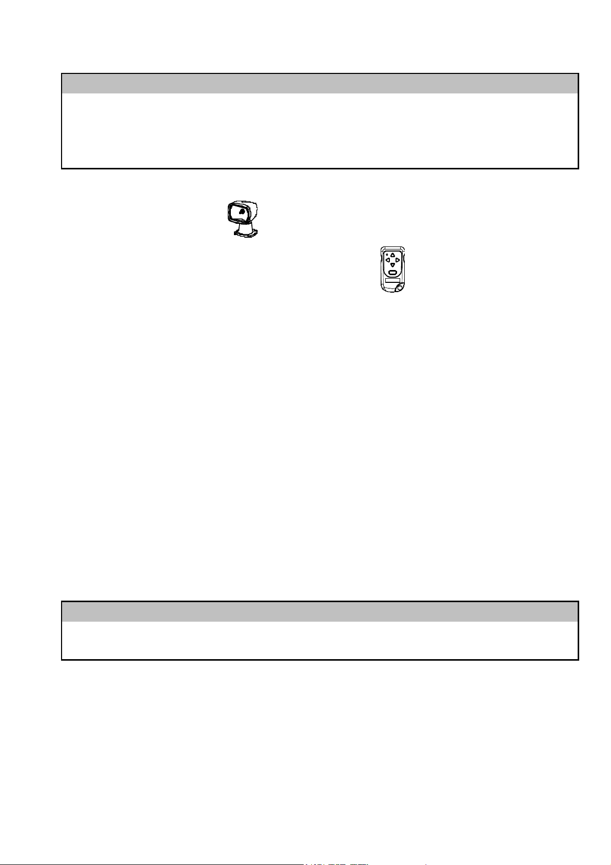
The GUEST 501 BEAMER remote control spotlight consists of:
(1)
The Spotlight / Receiver
(2)
The hand held wireless remote (R.F. Transmitter).
Item 1 is powered by 12 Volts D.C. Item 2 is powered by a 12 Volt Alkaline Battery
(provided with unit). See section titled “Installing Transmitter Battery”.
Installation
Range of operation of the wireless remote (R.F. Transmitter) is approximately 100 feet
under ideal conditions. The following will reduce the range:
(1)
A weak 12 Volt Alkaline Battery in the Transmitter.
(2)
Local radio interference.
(3)
Obstacles between the wireless remote (R.F. Transmitter) and Spotlight.
To provide control in the event of temporary signal loss or loss of your R.F. Transmitter,
we strongly suggest you replace the transmitter battery on a regular basis.
This unit is designed for 12 volt DC operation only.
CAUTION!
TO HELP PREVENT POSSIBLE SIGNAL LOSS, CHANGE BATTERIES YEARLY OR MORE OFTEN
Mounting the Spotlight
WITH EXTENDED USE
.
1. Select a horizontal, smooth surface to mount the spotlight in an upright position (not
upside down). Be sure you will have access to the underside of the chosen location,
and that you will be able to drill holes there without damaging existing wiring or
2

structures. Avoid locations where lines, anchors, sails or other hazards might
the light through the center hole in
damage the light.
NOTE: Mounting the light as far forward or as high as possible can help to reduce
reflected glare from the deck when the light is in use.
2. Remove the foam gasket from the base of the spotlight and use it as a template.
NOTE: Front mounting holes are further apart than rear holes. Mark the location of
the four corner holes and the center hole squarely onto the mounting surface with
pencil.
3. Drill five 5/16" (7mm) holes through the mounting surface at the marked points.
NOTE: Always wear eye protection when using power tools.
4. Return the foam gasket to the base of the spotlight, making sure that the two wires
exit through the center hole in the gasket.
5. Feed the two wires coming out of the base of
the mounting surface. A small amount of a non-silicone sealant, (such as StarBrite
Boat Caulk #83801), can be applied to where the bolts and the wires penetrate
the mounting surface.
CAUTION!
S
ILICONE BASED SEALANTS MAY CAUSE DAMAGE TO THE FOAM GASKET, OR TO THE BASE OF
THE SPOTLIGHT
.
6. A Marine grade plywood back plate is recommended to strengthen the installation.
7. Place the light on the mounting surface, lens facing forward, and align the 4 holes in
the light base and the foam gasket with the 4 corner holes drilled into the mounting
surface
8. Fasten the spotlight securely to the mounting surface using four 1/4" (6mm) stainless
steel Pan head screws, large flat washers, lock washers and nuts. Do not over
tighten.
9. It is recommended that the base of the spotlight be sealed to the mounting surface
using non-silicone sealant as in #5 above after installation for complete
waterproofing.
3
Installing Transmitter Battery
Note: Battery is included, but not installed to help prevent loss of battery strength when
new.
(1) Remove any static charges from your body by touching a metal grounded object.
(2) Remove Transmitter from console mounting bracket, by slightly bending the tab
back to release the transmitter from the bracket.
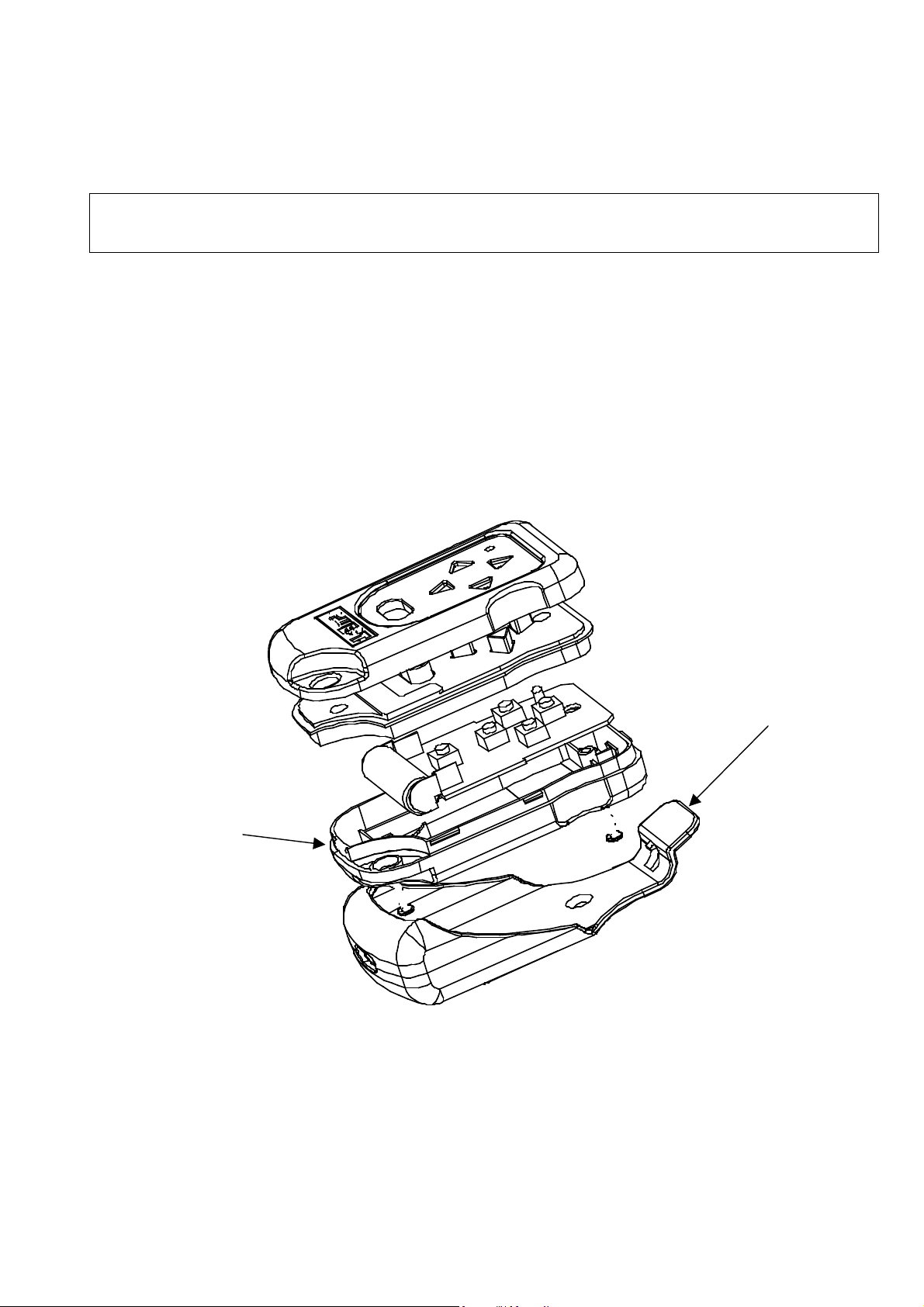
(3) Remove the two screws on the back of the transmitter with a Philips screwdriver.
With a coin, lightly pry open the transmitter case using the slot in the bottom corner
opposite of the key ring hole.
(4) Carefully separate the case halves. See illustration for disassembly below.
Tab (2)
Slot
(5) Place the 12 Volt Alkaline A23 battery in location per Figure 1 below paying close
attention to the + / - orientation.
4
 Loading...