

Guest 2608A-B, 2610A-B, 2611A-B Operation Manual
marinco.com
operations manual
Models 2608A-B,
2610A-B, 2611A-B
1. INTRODUCING THE CHARGER
The Guest model 2608A, 2610A and 2611A are designed to both recharge your batteries,
and extend your battery’s life in applications where it is stored for long periods of time.
They are “3-stage” electronic, completely automatic, lightweight, silent, battery chargers
and each output produces 12 Volts DC at either a full 5 or 6 Amps (model specific), while
using much less AC current than other charger types. Unlike automotive “trickle” chargers,
the 2608A, 2610A and 2611A will not boil off the electrolytes in properly installed and
maintained batteries. When the charger is attached to your batteries and plugged into
a standard 115 Volt / 60 Hz AC outlet, the red and green LED’s let you know the unit is
recharging and maintaining your batteries.
WARNING
!
THIS CHARGER SHOULD BE USED TO CHARGE ONLY LEAD ACID, AGM
OR GEL CELL TYPE BATTERIES. USE ON OTHER BATTERY TYPES MAY EXPLODE
AND CAUSE PERSONAL INJURY.
Models Amperage No. Of Banks Volts
2608A-B 6 Amps 1 Banks 12
2610A-B 5/5 Amps 2 Banks 12
2611A-B 5/5 Amps 2 Banks 12/24
IMPORTANT NOTICE
This manual contains important safety and operating instructions for the charger. Read the
entire manual before using. Also read all instructions and cautions for and on the charger,
batteries and equipment in the vicinity of the batteries.
BATTERY CHARGERS

2
Model 2608A-B/2610A-B/2611A-B operations manual
RISK OF EXPLOSIVE GASES! WORKING IN THE VICINITY OF LEAD ACID BATTERIES
IS DANGEROUS. BATTERIES GENERATE EXPLOSIVE GASES DURING NORMAL
OPERATION. FOR THIS REASON IT IS OF THE UTMOST IMPORTANCE THAT EACH
TIME BEFORE USING YOUR CHARGER YOU FOLLOW THE INSTRUCTIONS EXACTLY.
To reduce risk of battery explosion, follow these instructions and those published by
battery manufacturer and manufacturer of any equipment you intend to use in vicinity of
battery. Review cautionary marking on these products and on engine.
IMPORTANT SAFETY INSTRUCTIONS
1. Use of an attachment not recommended by the manufacturer may result in a risk of fire,
shock or injury.
2. To reduce the risk of damage to electric plug and cord, pull by plug rather than cord
when disconnecting the chargers.
3. An extension cord should not be used unless absolutely necessary. Use of improper
extension cord could results in a risk of fire and electric shock. If an extension cord must
be used, make sure:
a) That pins on plug of extension cord are the same number, size and shape as those of
the plug on the charger;
b) That the extension cord is properly wired and in good electrical condition; and
c) That wire size is large enough for ac ampere rating of the charger as specified below
Cord length 25' 50' 100'
Cable AWG size 18 16 14
4. Do not operate charger with a damaged cord or plug.
5. Do not operate the charger if it has received a sharp blow, been dropped, or otherwise
damaged in any way.
6. Do not attempt to disassemble the charger.
7. To reduce the risk of injury unplug charger from outlet before attempting any
maintenance or cleaning. Turning off controls alone will not reduce the risk.
8. Do not expose charger to rain or snow.
PERSONAL SAFETY PRECAUTIONS
Adhere to the following personal safety precautions when installing or working with the
chargers:
1. Someone should be within voice range or close enough to come to your aid when you
work near a lead-acid battery.
2. Have plenty of fresh water and soap nearby in case battery acid contacts skin, clothing,
or eyes.
3. Wear complete eye protection and clothing protection. Avoid touching eyes while
working near a battery.
4. If battery acid contacts skin or clothing, wash them immediately with soap and water. If
acid enters the eye, flood the eye with cold, running water for at least ten minutes and
get medical attention.
5. Never smoke or allow an open flame in the vicinity of the battery.
6. Do not drop a metal tool onto the battery. It may spark, short circuit the battery and may
cause an explosion.
7. Remove all personal metal items such as rings, bracelets, necklaces, and watches when
working near a lead-acid battery. A battery can produce short circuit currents high

3
operations manual Model 2608A-B/2610A-B/2611A-B
enough to weld a ring or the like to metal, causing a severe burn.
8. Use charger for charging a lead acid, AGM or gel battery only. It is not intended to
supply power to a low voltage electrical system other than in a starter motor application.
Do not use charger for charging dry cell batteries that are commonly used with home
appliances. These batteries will burst and cause injury to persons and damage to
property.
9. Never charge a frozen battery.
PREPARING TO CHARGE PRECAUTIONS
Before charging a battery with the charger, read the following precautions:
1. Do NOT operate the charger if the cables or an LED is damaged.
2. Make sure all accessories on the product you are charging are OFF.
3. If the battery or batteries must be removed from the product, always remove the
grounded terminal from the battery first. Make sure all accessories in the product are
off, so as not to cause an electrical arc.
4. Be sure the area around the battery is well ventilated while the battery is being charged.
Gas can be forcefully blown away using a piece of cardboard or other non-metallic
material as a “hand fan”.
5. Clean battery terminals. Be careful to keep corrosion from coming in contact with eyes.
6. Add distilled water in each cell until battery acid reaches levels specified by the battery
manufacturer, if applicable. Do not overfill. For a battery without cell caps, carefully
follow the manufacturer’s recharging instructions.
7. Study all battery manufacturer's specific precautions while charging and recommended
rates of charge.
8. Determine voltage of battery by referring to product's manual, and make sure it matches
output rating of battery charger.
AC CONNECTION AND GROUNDING PRECAUTIONS
DANGER
!
DO NOT OPERATE THIS CHARGER WITH A TWO BLADED ADAPTER PLUG
OR EXTENSION CORD. DOING SO CAN RESULT IN SERIOUS PERSONAL INJURY.
AFTER SECURING THE BATTERY CONNECTIONS, PLUG THE AC LINE CORD INTO
AN AVAILABLE AC OUTLET THAT IS PROTECTED BY A GROUND FAULT CIRCUIT
INTERRUPTER (GFCI) BREAKER.
GROUNDING AND AC POWER CORD CONNECTION INSTRUCTIONS: Charger
should be grounded to reduce risk of electric shock. Charger is equipped with an electric
cord having an equipment-grounding conductor and a grounding plug. The plug must be
plugged into an outlet that is properly installed and grounded in accordance with all local
codes and ordinances.
NOTE: AC Line Cord color coding is EU style. Line = Brown, Neutral = Blue, Ground =
Green
DANGER
!
Never alter AC cord or plug provided – if it will not fit outlet, have proper outlet
installed by a qualified electrician. Improper connection can result in a risk of an electric
shock.
2. INSTALLING THE CHARGER
CHOOSING CHARGING LOCATION
1. The charger should have at least eight inches of unobstructed area on all sides of the
unit for effective cooling. The case of this charger will become warm during operation.
Because the charger is convection cooled (airflow over the back of the charger), the

4
Model 2608A-B/2610A-B/2611A-B operations manual
optimum mounting position for the charger is vertical. Mounting on its back on a
horizontal surface may cause the charger to slightly reduce amperage output due
to the thermal protection built in. Do not install the charger on carpeted, upholstered,
or varnished surfaces.
2. Locate charger as far away from battery as dc cables permit.
3. Never place charger directly above battery being charged; gases from battery will
corrode and damage charger.
4. Never allow battery acid to drip on charger when reading electrolyte specific gravity or
filling battery.
5. Do not operate charger in a closed-in area or restrict ventilation in any way.
6. Do not set a battery on top of charger.
MOUNTING THE CHARGER
1. Use corrosion resistant 3/16” dia. or # 10 bolts, backed by a flat washer, and secured to
the mounting surface with a split-ring lock washer.
2. Hold the charger to the mounting surface and mark the holes.
3. Remove the charger and drill the mounting holes.
4. Align the charger and assemble the mounting hardware. Secure the charger.
DC CONNECTION PRECAUTIONS
1. Connect and disconnect dc outputs only after removing ac cord from electric outlet.
Never allow the ring terminals to touch each other
2. Check polarity of the battery posts. The POSITIVE (POS., P, +) battery post usually has
a larger diameter than the NEGATIVE (NEG., N, -) post. Connect Red charger output
wire to POSITIVE post, Black charger wire to NEGATIVE. See below diagrams for more
details.
3. Do not face the battery when making the final connection.
BATTERY SIZE RECOMMENDATIONS
The recommended maximum battery size per 5 amp bank is 60AH.
The recommended maximum battery size per 6 amp bank is 72AH.
2608A CONNECTIONS
Model
Output
Volts
Output
Amps
Banks
DC
Cable
Size
Size
(inches)
L x W x H
Input
Volts
Input
Amps
Max
2608A-B 12 6 1 4’
3.5 x 6.4
x 2.25
115VAC
50/60Hz
2 Amps
5
operations manual Model 2608A-B/2610A-B/2611A-B
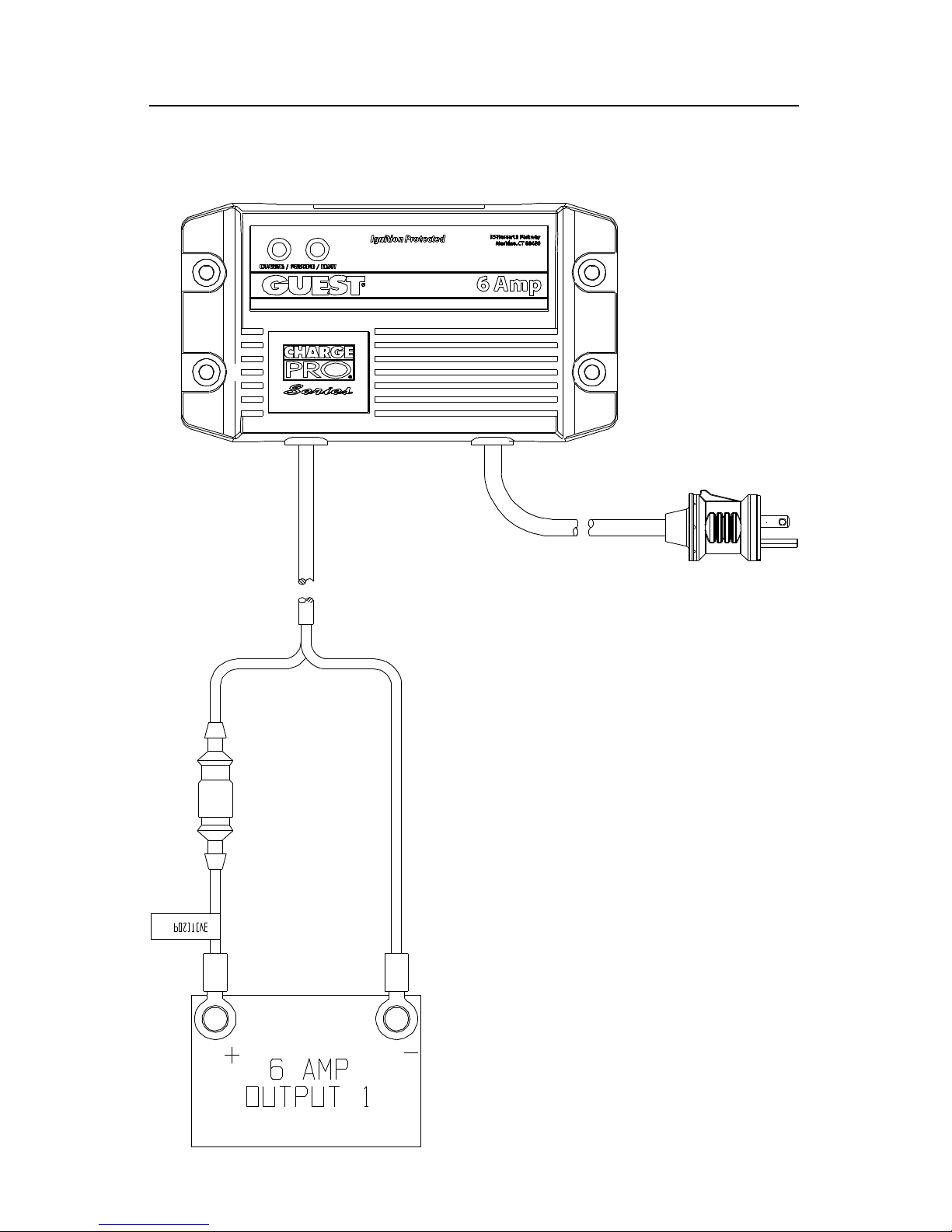
DIAGRAM 3. 2608A-B (6 AMPS) USED WITH 1 12V BATTERY

6
Model 2608A-B/2610A-B/2611A-B operations manual
2611A-B CONNECTIONS
Model
Output
Volts
Output
Amps
Banks
DC
Cable
Size
Size
(inches)
L x W x H
Input
Volts
Input
Amps
Max
2611A-B 12/24 5/5 2 4’/4’
4.25 x 7
x 2.42
115VAC
50/60Hz
2.5
Amps
E
N
G
I
N
E
S
T
A
R
T
B
A
T
T
E
R
Y
R
E
F
E
R
T
O
P
R
O
D
U
C
T
M
A
N
U
A
L
F
O
R
T
R
O
L
L
I
N
G
A
P
P
L
I
C
A
T
I
O
N
S
POSIT IVE
POSIT IVE
OUTPUT #2
OUTPUT #1
ENGINE START
(OR TROLLING)
AC
DIAGRAM 4. 2611A-B (5/5 AMPS) USED WITH 2 INDEPENDENT 12V BATTERIES

7
operations manual Model 2608A-B/2610A-B/2611A-B
2611A-B CONNECTIONS: FOR THE 2611A-B, OUTPUT 1 AND OUTPUT 2 MAY BE
CONNECTED IN PARALLEL FOR A 12 V 10 AMP OUTPUT. OUTPUT 1 AND 2 MAY
BE CONNECTED IN SERIES FOR A 24 V SYSTEM. SEE DIAGRAM 5.
DIAGRAM 5: 2611A-B USED IN A 24 V SYSTEM
E
N
G
I
N
E
S
T
A
R
T
B
A
T
T
E
R
Y
R
E
F
E
R
T
O
P
R
O
D
U
C
T
M
A
N
U
A
L
F
O
R
T
R
O
L
L
I
N
G
A
P
P
L
I
C
A
T
I
O
N
S
POSIT IVE
POSIT IVE
OUTPUT #2
OUTPUT #1
ENGINE START
(OR TROLLING)
AC

8
Model 2608A-B/2610A-B/2611A-B operations manual
2611A-B CONNECTIONS
Model
Output
Volts
Output
Amps
Banks
DC
Cable
Size
Size
(inches)
L x W x H
Input
Volts
Input
Amps
Max
2610A-B 12 5/5 2 N/A
4.25 x 7
x 2.42
115VAC
50/60Hz
2.5
Amps
9
operations manual Model 2608A-B/2610A-B/2611A-B
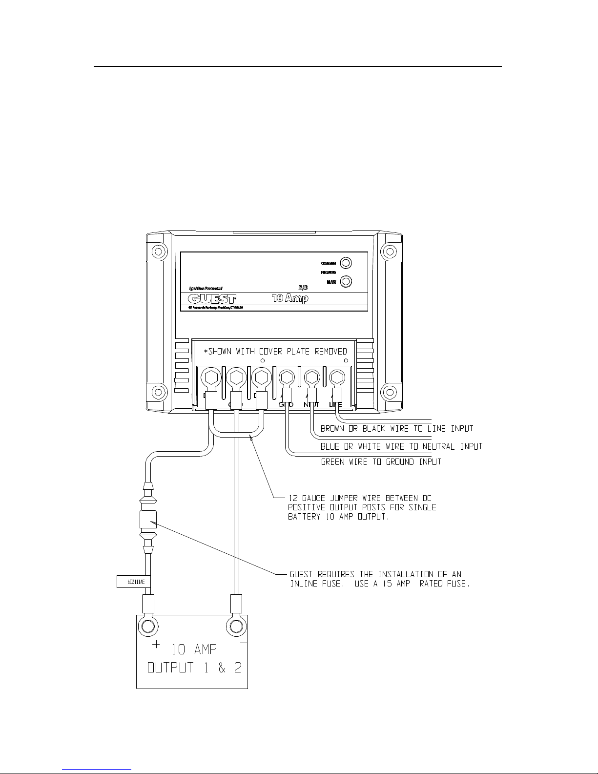
DIAGRAM 6: 2610A-B (5/5 AMPS) USED WITH 2 12V BATTERIES
THE 2610A-B CAN BE USED ON 2 X 12 VOLT INDEPENDENT BATTERIES. T MAY
NOT BE USED FOR A 24 VOLT SYSTEM, THE OUTPUTS MAY NOT BE WIRED IN
SERIES. THE 2610A-B MAY BE USED TO CHARGE ONE SINGLE BATTERY. WHEN
DOING THIS, A 12 GAUGE JUMPER WIRE MUST BE ADDED BETWEEN OUTPUT
POSTS DC + #1 AND DC + #2. SEE DIAGRAM 7.
DIAGRAM 7: 2611A-B USED IN A SINGLE BATTERY SYSTEM
 Loading...