

Guest 2530 Owner's Manual

OWNER’S MANUAL
Auxiliary
Battery
SINGLE INPUT 120A MAXIMUM BATTERY ISOLATORS
Models Current Rating No. of outputs
2530 120A 2
IMPORTANT SAFETY INSTRUCTION
This manual contains important safety and wiring instructions for the
isolator. Read the entire manual before using. Also read all instructions
and cautions for the isolator, batteries and equipment in the vicinity of the
batteries.
RISK OF EXPLOSIVE GASES! WORKING IN THE VICINITY OF
LEAD ACID BATTERIES IS DANGEROUS. BATTERIES
GENERATE EXPLOSIVE GASES DURING NORMAL OPERATION.
THEREFORE IT IS OF THE UTMOST IMPORTANCE THAT WHEN
INSTALLING THE ISOLATOR THESE INSTRUCTIONS ARE
FOLLOWED.
Personal Safety Precautions
Adhere to the following personal safety precautions when installing or
working with the isolators:
1. Someone should be within voice range or close enough to
come to your aid when you work near a lead-acid battery.
2. Have plenty of fresh water and soap nearby in case battery
acid contacts skin, clothing, or eyes.
3. Wear complete eye protection and clothing protection.
Avoid touching eyes while working near a battery.
4. If battery acid contacts skin or clothing, wash them
immediately with soap and water. If acid enters the eye,
flood the eye with cold, running water for at least ten
minutes and get medical attention.
5. Never smoke or allow an open flame in the vicinity of the
battery.
6. Do not drop a metal tool onto the battery. It may shortcircuit the battery, spark and may cause an explosion.
7. Remove all personal metal items such as rings, bracelets,
necklaces, and watches when working near a lead-acid
battery. A battery can produce short circuit currents high
enough to weld a ring or the like to metal, causing a severe
burn.
Preparing to Charge Precautions
Before charging a battery, read the following precautions:
1. If the battery or batteries must be removed from the
product, always remove the grounded terminal from the
battery first.
2. Be sure the area around the battery is well ventilated while
the battery is being charged. Gas can be forcefully blown
away using a piece of cardboard or other non-metallic
material as a “hand fan”.
3. Clean battery terminals. Be careful to keep corrosion from
coming into contact with eyes.
4. Add distilled water in each cell until battery acid reaches
levels specified by the battery manufacturer, if applicable.
Do not overfill. Check water levels frequently. For a battery
without cell caps, carefully follow the manufacturer’s
recharging instructions.
5. Never allow the charger battery connection ring terminals to
touch each other.
6. NEVER charge a frozen battery.
R
INTRODUCTION
The Guest Battery Isolators are specifically designed to efficiently utilize the
energy produced by the alternator and distribute the power evenly to each
battery.
The isolators are connected between the alternator(s) and the batteries.
The difficulty in connecting the isolators is due to the large variety of
alternator configurations. This manual illustrates the most common wiring
configurations.
When installing a Guest Battery Isolator make sure the proper circuit breaker
and wire sizes are utilized.
The Guest Battery Isolators are designed for alternator systems with
negative ground and batteries of the same voltage level.
INSTALLATION
Choosing the Battery Isolator location
The battery isolator should have at least eight inches of unobstructed area
on all sides of the unit for effective cooling. The case of the battery isolator
will become hot during operation. Because the battery isolator is convection
cooled (airflow over the fins of the heat sink), the battery isolator MUST be
mounted with the fins in the vertical position. Mounting on its back on a
horizontal surface may cause the battery isolator to produce excessive heat,
Do not install the battery isolator on carpeted, upholstered, or varnished
surfaces.
Mounting the Battery Isolator
1. Use corrosion resistant #10 sized screws or bolts, backed by a flat
washer, and secured to the mounting surface with a split-ring lock
washer.
2. Hold the isolator to the mounting surface and mark the holes.
3. Remove the isolator and drill the mounting holes.
4. Allign the isolator and assemble the mounting hardware secure.
Wire Size
Rating
50 Amps 10AWG 10AWG 8AWG 8AWG
70 Amps 8AWG 8AWG 6AWG 6AWG
100 Amps 8AWG 6AWG 6AWG 4AWG
120Amps 4AWG 4AWG 2AWG 2AWG
0 – 15ft 15 – 20ft 20 – 25ft 25 – 30ft
Recommended Wire Size Current
Typical Wiring Configuration
Diagram 1 – Standard Alternator to Battery Isolator Configuration
Main
Battery
+
Alternator
120A Max
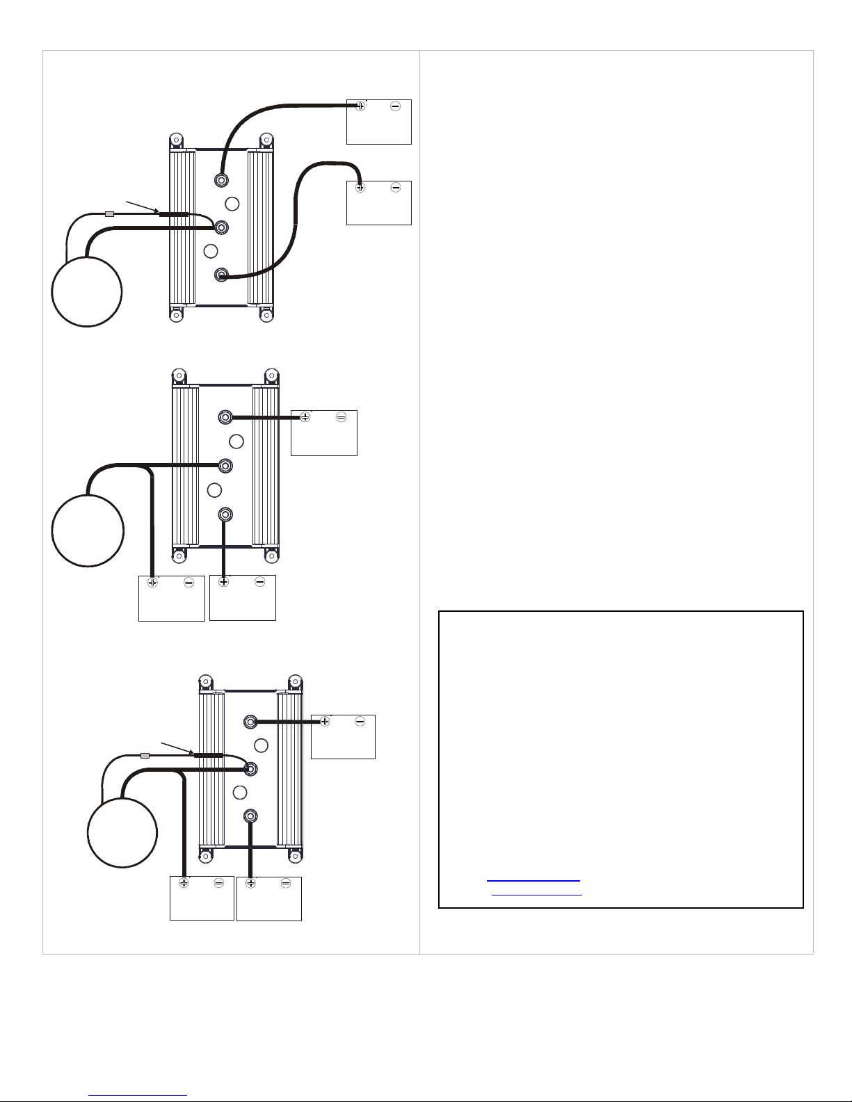
Typical Wiring Configuration (continued)
Auxiliary
Battery
Auxiliary
Auxiliary
Main
Auxiliary
Auxiliary
Main
Diagram2 – Alternator to Battery Isolator with R-Kit
R-KIT
Guest P/N U-3059
Alternator
120A Max
+
R
Battery
Diagram 3 – Alternator to Battery Isolator with additional battery
Battery
+
Alternator
120A Max
Battery
Battery
Battery
Battery
Battery
Diagram 4 – Alternator to Battery Isolator with R-Kit and additional
battery
R-KIT
Guest P/N U-3059
Alternator
70A Max
+
R
730863 Rev A
Main
Battery Isolator Testing
1. Remove all wire connections from the isolator.
2. Setup a digital multi-meter (DMM) in the diode test mode.
3. Connect the red probe from the DMM to the alternator input (A)
and the black probe from the DMM to the battery output terminal
to be tested. A good isolator connection will show a reading of 0.4
to 0.6VDC.
4. Connect the DMM black probe to the alternator input (A) and the
red probe to the battery output terminal to be tested. A good
isolator connection will show a reading of OL.
5. Repeat steps 3 and 4 for the other battery output terminals.
Maintaining the Battery Isolator
Periodically clean both battery and isolator terminals with baking soda and
tighten all connections. No other maintenance on the isolator is required.
For two (2) years from the date of original purchase, The Guest Co.
will, at its discretion, repair or replace for the original consumer, free of
charge, any parts found defective in material or workmanship.
Proof of purchase is required: A computerized register receipt is
required. Hand-written receipts are not accepted for warranty proof of
purchase. In the absence of a receipt, warranty period will be
calculated from date of manufacture printed or stamped on the
product.
There is no other expressed warranty. Implied warranties, including
those of merchantability and fitness for a particular purpose, are
limited to two years from the date of purchase. This is the exclusive
remedy and consequential damages are excluded where permitted by
law.
Tel: 707-226-9600
Fax:707-226-9670
e-mail: info@marinco.com
website: www.marinco.com
LIMITED WARRANTY
 Loading...