

Page 1

Operating instructions
Güntner Motor Management GMM step
www.guentner.de
Operating instructions – Güntner Motor Management GMM step V_3.0
Page 2

Contents
Page 2 / 107
1 General notes............................................................................... 6
1.1 Safety instructions.............................................................................6
1.2 Proper intended use......................................................................... 6
1.3 Transport and storage, copyright notice........................................ 7
1.4 Warranty and liability........................................................................7
1.5 Manufacturer and supplier address................................................8
1.6 EMC-compliant installation..............................................................8
2 Commissioning GMM step......................................................... 9
2.1 The initial commissioning procedure........................................... 10
3 Construction of the GMM step................................................ 14
3.1 Remote controllers..........................................................................14
3.1.1 Functional description................................................................................... 14
3.1.1.1 Configurable step generator....................................................................... 18
3.1.2 Installation / Operating conditions.......................................................... 19
3.1.3 Connections....................................................................................................... 21
4 Display and operation...............................................................28
4.1 Info menu......................................................................................... 28
4.2 Status displays in the Info menu..................................................29
4.3 Operation.......................................................................................... 30
4.4 Edit mode......................................................................................... 31
4.5 Selection mode................................................................................32
4.6 Configuration....................................................................................33
4.6.1 Configuration table......................................................................................... 33
4.6.2 Command outputs..........................................................................................35
4.7 Control inputs.................................................................................. 36
4.7.1 Enabling of GMM step.................................................................................. 36
4.7.2 External fault/External manual mode.....................................................37
4.7.3 Switching to 2nd setpoint (or between heating and cooling
mode)....................................................................................................................37
4.7.4 Control inputs on the GIOD........................................................................38
4.7.4.1 Fault report inputs.......................................................................................... 38
4.7.4.2 Remote acknowledgement..........................................................................38
4.8 Analogue inputs...............................................................................39
4.8.1 Connecting a pressure sensor to AI1/AI2.............................................39
4.8.2 External power signal connection to AI1/AI2......................................40
4.8.3 Connecting a passive temperature sensor on AI2............................ 41
4.8.4 Connecting a temperature sensor on AI3............................................ 41
4.8.5 0-10V voltage signal connection to AI4.................................................42
4.9 Analogue outputs............................................................................ 43
Operating instructions – Güntner Motor Management GMM step V_3.0
© Güntner GmbH & Co. KG
Page 3

Page 3 / 107
4.10 Operating menu...............................................................................44
4.10.1 Actual values..................................................................................................... 45
4.10.1.1 Input current values.......................................................................................45
4.10.1.2 Ambient temperature.................................................................................... 45
4.10.1.3 Control value..................................................................................................... 45
4.10.1.4 Air volume.......................................................................................................... 46
4.10.1.5 Steps..................................................................................................................... 46
4.10.2 Status....................................................................................................................47
4.10.2.1 Operating mode............................................................................................... 47
4.10.2.2 Mode..................................................................................................................... 48
4.10.2.3 External release - Status.............................................................................. 48
4.10.2.4 GMM type........................................................................................................... 48
4.10.2.5 Number of steps............................................................................................. 48
4.10.2.6 Number of error inputs................................................................................48
4.10.2.7 Fancycling........................................................................................................... 48
4.10.2.8 Heat exchanger................................................................................................ 49
4.10.2.9 Refrigerant.......................................................................................................... 49
4.10.2.10 Hardware and software versions.............................................................. 49
4.10.2.11 Bus module........................................................................................................49
4.10.2.12 Threshold status.............................................................................................. 49
4.10.2.13 Emergency setting status............................................................................ 49
4.10.2.14 GHM Controller.................................................................................................50
4.10.3 Setpoints..............................................................................................................50
4.10.3.1 Setpoint 1........................................................................................................... 50
4.10.3.2 Setpoint 2........................................................................................................... 50
4.10.3.3 Threshold value................................................................................................51
4.10.4 Alerts..................................................................................................................... 52
4.10.4.1 Alert memory.................................................................................................... 52
4.10.5 Language.............................................................................................................53
4.10.5.1 Language selection.........................................................................................53
4.10.6 Time.......................................................................................................................54
4.10.6.1 Time setting.......................................................................................................54
4.10.7 Date....................................................................................................................... 55
4.10.7.1 Set date............................................................................................................... 55
4.10.8 Manual mode.................................................................................................... 56
4.10.8.1 Manual mode settings.................................................................................. 56
4.11 Service...............................................................................................58
4.11.1 Control parameters.........................................................................................59
4.11.1.1 Control parameters Kp, Ti and Td...........................................................59
4.11.1.2 Cooling/heating control parameter mode............................................ 60
4.11.1.3 Base control value and Start control value control parame-
ters......................................................................................................................... 60
4.11.2 Heat exchanger................................................................................................ 61
4.11.2.1 Heat exchanger type......................................................................................61
Operating instructions – Güntner Motor Management GMM step V_3.0
© Güntner GmbH & Co. KG
Page 4

Page 4 / 107
4.11.3 Refrigerant.......................................................................................................... 62
4.11.3.1 Refrigerant selection...................................................................................... 62
4.11.4 Operating mode............................................................................................... 63
4.11.4.1 Auto internal......................................................................................................63
4.11.4.2 Auto external..................................................................................................... 63
4.11.4.3 Auto external BUS.......................................................................................... 64
4.11.4.4 Slave external....................................................................................................64
4.11.4.5 Slave external BUS......................................................................................... 64
4.11.5 Bypass.................................................................................................................. 65
4.11.5.1 Software bypass (SW bypass)................................................................... 65
4.11.5.2 GIOD bypass......................................................................................................66
4.11.6 Step parameters.............................................................................................. 67
4.11.6.1 Fancycling........................................................................................................... 67
4.11.6.2 Threshold value................................................................................................67
4.11.6.3 Off hysteresis.....................................................................................................67
4.11.6.4 Dead time........................................................................................................... 68
4.11.6.5 Thermocontact reset......................................................................................68
4.11.6.6 Running times.................................................................................................. 69
4.11.7 Features................................................................................................................70
4.11.7.1 Number of setpoints......................................................................................70
4.11.7.2 Offset setpoint...................................................................................................71
4.11.7.3 Subcooler function..........................................................................................72
4.11.7.4 External BUS module....................................................................................73
4.11.7.5 Threshold value................................................................................................73
4.11.7.6 GHM Controller.................................................................................................76
4.11.7.7 Maintenance run..............................................................................................76
4.11.8 I/O configuration..............................................................................................78
4.11.8.1 Analogue inputs............................................................................................... 78
4.11.8.1.1 Current inputs AI1.......................................................................................... 79
4.11.8.1.2 Switchover input AI2......................................................................................80
4.11.8.1.3 AI3 input temperature sensor................................................................... 81
4.11.8.1.4 0..10V AI4 input...............................................................................................81
4.11.8.2 Digital inputs..................................................................................................... 82
4.11.8.3 Analogue outputs............................................................................................ 82
4.11.8.4 Digital outputs.................................................................................................. 83
4.11.9 SI/IP selection...................................................................................................84
4.11.9.1 SI/IP units system...........................................................................................84
4.11.10 Factory setting.................................................................................................. 85
4.11.10.1 Control reset (factory setting)....................................................................85
4.11.11 Delivery condition............................................................................................86
4.11.11.1 Control reset (delivery condition).............................................................86
5 Faults and troubleshooting.......................................................87
5.1 General notes...................................................................................87
Operating instructions – Güntner Motor Management GMM step V_3.0
© Güntner GmbH & Co. KG
Page 5

Page 5 / 107
6 Technical data............................................................................ 88
6.1 Component dimensions - Dimensions / Weight......................... 88
7 Electrical properties of the components................................90
8 External control value scaling..................................................93
9 Factory setting............................................................................94
10 Error messages and warnings................................................. 96
11 Troubleshooting tips............................................................... 101
12 Index..........................................................................................102
13 Picture index............................................................................106
14 Table index...............................................................................107
Operating instructions – Güntner Motor Management GMM step V_3.0
© Güntner GmbH & Co. KG
Page 6

1 General notes
1.1 Safety instructions
In order to prevent serious physical injuries or major material damage, work on or with the
unit may be performed only by authorised persons with appropriate training and qualifications who are familiar with the set-up, installation, commissioning and operation of speed controllers. These persons must read the operating instructions carefully before the installation
and commissioning. In addition to the operating instructions and national accident prevention
regulations, all recognised technical rules (safety and professional work under UVV, VBG, VDE
etc.) must be followed.
Repairs to the device may only be made by the manufacturer or a repair centre authorised by
the manufacturer.
UNAUTHORISED AND IMPROPER INTERVENTIONS WILL INVALIDATE THE WARRANTY!
The applicable national accident prevention regulations must be followed when working on control
units under voltage.
Page 6 / 107
1.2 Proper intended use
The unit is intended only for the purposes agreed in the order confirmation. Any other application or use for any additional purpose, is not a proper intended use. The manufacturer accepts no liability for any injury or damage arising from unintended use. Proper intended use
is also contingent on compliance with the installation, operating and maintenance procedures
described in these operating instructions. The technical data and the details of the connection
assignments can be found on the type plate and in the instructions, and must be complied
with.
Electronic equipment is not fundamentally failsafe! The user must therefore ensure that his system reverts to a safe condition in the event of failure of the equipment. The manufacturer accepts
no responsibility for any damage to life and limb or to material goods and assets in the event of
failure to comply with this provision and in the event of improper use.
The electrical installation must be performed in accordance with the relevant regulations (e.g.
cable cross-sections, fuses, earth conductor connections, etc.). Additional information is included in the documentation. If the control unit is used in a particular area of application, the
required standards and regulations must be complied with.
Operating instructions – Güntner Motor Management GMM step V_3.0
© Güntner GmbH & Co. KG
Page 7

1.3 Transport and storage, copyright notice
The controllers are packaged appropriately for transport and may only be transported in
their original packaging. Avoid any impacts and collisions. Unless otherwise noted on the
packaging, the maximum stacking height is 4 packs. When you receive the equipment,
check for any damage to the packaging or the controller.
Store the equipment in its original packaging and protected from the weather, and avoid extremes of heat and cold.
Subject to technical changes in the interests of further development. Therefore no claims
may be derived from information, images and drawings; errors excepted!
All rights, including rights created by patent grant or other registration, are reserved.
These operating instructions are the copyright of
GÜNTNER GmbH & CO. KG
Fürstenfeldbruck
1.4 Warranty and liability
The current General Terms and Conditions of Sales and Delivery of Güntner GmbH & Co. KG
apply.
Page 7 / 107
See the homepage at http://www.guentner.de
Operating instructions – Güntner Motor Management GMM step V_3.0
© Güntner GmbH & Co. KG
Page 8

1.5 Manufacturer and supplier address
Should you have a problem with any of our equipment, or any questions, suggestions or
special requests, simply contact
Güntner GmbH & Co. KG
Hans-Güntner-Strasse 2-6
D-82256 Fürstenfeldbruck, Germany
Service Telephone Germany:
0800 48368637
0800 GUENTNER
Service Telephone Worldwide:
+49 (0)8141 242-4815
Fax. +49 (0)8141 242-422
service@guentner.de
http://www.guentner.de
Page 8 / 107
Copyright © 2015 Güntner GmbH & Co. KG
All rights, including rights of photomechanical reproduction and storage in electronic form,
are reserved.
1.6 EMC-compliant installation
Controllers in the GMM step series fulfil the requirements of EN 61000-6-2 as regards resistance to EMC interference and those of EN 61000-6-3 as regards emissions.
They also comply with standards IEC 61000-4-4/-5/-6/-11 for grid-bound interference. In order to guarantee EM compatibility, the following points must be noted:
All measurement and signalling lines must be connected via shielded cables.
• The shielding of measuring, signal and bus lines must be earthed at one end only.
• Suitable shielding and routing measures must be taken to ensure that mains cables and motor cables do not give rise to any interference in signal and control lines.
If the equipment is installed in a switch cabinet, proper attention must be given to the temperature
inside the cabinet. Güntner switch cabinets are provided with sufficient ventilation.
ADVICE
Operating instructions – Güntner Motor Management GMM step V_3.0
© Güntner GmbH & Co. KG
Page 9

2 Commissioning GMM step
The GMM step must be set up in accordance with the configuration of the heat exchanger and
the fans. This commissioning process determines the performance of the heat exchanger.
The GMM step automatically detects whether commissioning has been carried out when it is
switched on and, if it has, continues with normal operation.
If the GMM step detects that this has not yet been done, it initiates the commissioning procedure. When this procedure has been completed, all the specified parameters are saved.
All values set up by the commissioning can also be viewed and changed individually later on
in the menus.
Page 9 / 107
Operating instructions – Güntner Motor Management GMM step V_3.0
© Güntner GmbH & Co. KG
Page 10

2.1 The initial commissioning procedure
If it is recognized that commissioning has not yet taken place, the following values are interrogated and set up in accordance with the following flow chart.
Page 10 / 107
Operating instructions – Güntner Motor Management GMM step V_3.0
© Güntner GmbH & Co. KG
Page 11

Page 11 / 107
If it is recognized that a commissioning is required, the commissioning menu is displayed.
Operating instructions – Güntner Motor Management GMM step V_3.0
© Güntner GmbH & Co. KG
Page 12

Page 12 / 107
Operating instructions – Güntner Motor Management GMM step V_3.0
© Güntner GmbH & Co. KG
Page 13

Page 13 / 107
Operating instructions – Güntner Motor Management GMM step V_3.0
© Güntner GmbH & Co. KG
Page 14

3 Construction of the GMM step
Construction of the GMM step: left GRCS.1, right GIOD.1
3.1 Remote controllers
3.1.1 Functional description
Functional description of GRCS.1
Page 14 / 107
The GRCF.1 is used to control step controllers. As a minimal solution, GRCS.1 can control up
to four steps.
Variant GMM step basic
If you need more steps or additional functions you will need to combine the GRCS.1 with a
GIOD.1 expansion module, ERP no. 5204183.
Variant GMM step professional
Operating instructions – Güntner Motor Management GMM step V_3.0
© Güntner GmbH & Co. KG
Page 15

Page 15 / 107
In order to operate the controller it must have a power supply and must be enabled via digital
input DI1. If it is not enabled the process will not be regulated.
The unit has an internal PID controller, whose parameters (amplification factor, integral and
differential time) can be configured either per menu or via an external bus module.
The setpoint can be given via the internal menu, an external analogue value or via an external
bus module.
The current value is determined via a pressure sensor (4-20mA), a temperature sensor (KTY,
GTF210) or a 0-10V signal.
The relay outputs controlling the output stages are switched as appropriate for the setpoint
and the number of steps. A switch-on threshold can be configured for each step.
The integrated function “Fancycling” makes it possible to balance the running times for the individual fans.
The digital inputs are designed as potential-free contacts that must be connected to +24V. As
well as enable (DI1), digital inputs are also used to control external errors (DI2) and the setpoint switchover (DI3).
ADVICE
Please note that connecting the wrong voltage (e.g. 230V) may seriously damage the controller.
The relay outputs are used to control the output stages. Depending on the configuration (the
number of steps and your GMM step basic or GMM step professional configuration) a number
of special functions may also be available. The function assignment is described in the configuration table.
See Configuration table, Page 33
Analogue output AO1 shows the current control value from the controller (0-100%) as a voltage in the range 0-10V. Analogue output AO2 can be used to control an additional subcooler.
The CAN interface of the GRCS.1 is an internal interface for communicating with other Güntner equipment (e.g. the expansion module GIOD.1). The following communications modules are available for external bus connections: for Modbus (GCMM.1, ERP no. 5204182) or
Profibus (GCMP.1, ERP no. 5204543).
Operating instructions – Güntner Motor Management GMM step V_3.0
© Güntner GmbH & Co. KG
Page 16

Page 16 / 107
Functional description of GIOD.1
The GIOD.1 is controlled via CAN by a Güntner controller. The GIOD.1 possesses 16 digital inputs with a rated voltage of 24VDC and 8 relay outputs. The bus address of the GIOD.1 (node
ID) is set up using a rotary encoding switch. The address 0xF may not be used for this.
ADVICE
To operate the GIOD on GMM step professional the rotary switch must always be set to address1.
The GIOD reads this address only when first switched on.
To ensure the bus connection between the controller and one or more other units works correctly, bus termination must be activated at the beginning and end of the bus connection by
setting the units’ DIP switches labelled “Term”. They must be placed in the “ON” position to
activate the termination. Units that are in the middle of the bus and therefore permitted to
transfer the bus signal may not have bus termination activated.
The status of the inputs and outputs is indicated by LEDs on the front of the casing. A lit LED
against the digital inputs signifies that the corresponding input is receiving a “high” signal. A
lit LED against the relay outputs signifies that the closer contact is closed. A power LED signifies that the internal electronic components are receiving power.
There is also a status display for the bus connection that involves two LEDs.
Operating instructions – Güntner Motor Management GMM step V_3.0
© Güntner GmbH & Co. KG
Page 17

Page 17 / 107
Bus status LED Description
On The GIOD.1 is in operation
Flashing 50:50 The GIOD.1 can be taken into operation
Brief single flash The GIOD.1 is currently stopped
Three flashes with error LED The software is attempting to overrun the stack on the
GIOD.1
Alternate flashing with error
LED
Synchronous fast flashing with
error LED
Bus error LED Description
Off Unit is operating correctly
On There is a static fault on the CAN bus
Brief single flash The warning limit has been reached in the CAN controller
Double flashing A fault was detected in the lifeguard, nodeguard or heart-
Three flashes with the bus status LED
Alternate flashing with the bus
status LED
Synchronous fast flashing with
error LED
Power LED Description
On The internal electronics are receiving power
A “layer setting service” is being performed on the GIOD.1
Reset to default has been selected on the rotary coding
switch (setting “F”)
beat
The software is attempting to overrun the stack on the
GIOD.1
A “layer setting service” is being performed on the GIOD.1
Reset to default has been selected on the rotary coding
switch (setting “F”)
Off The unit is not powered or is reverse-poled
Digital input LED Description
On The digital input detects a “High” signal
Off The digital input detects a “Low” signal
Digital output LED Description
On The digital output is closed
Off The digital output is open
Operating instructions – Güntner Motor Management GMM step V_3.0
© Güntner GmbH & Co. KG
Page 18

3.1.1.1 Configurable step generator
The step generator comprises three main components
1. Step generator
The step generator generates a bit pattern for the outputs that are to be switched depending
on the number of steps, their thresholds, their hysteresis and the hold-off time (=default setting).
Page 18 / 107
2. Fancycling
Fancycling ensures even distribution of the running times for the outputs (the fans). To this
end it records and evaluates the running times of all the active outputs.
Active fancycling means,
- when a step is switched on, the output with the least running time is activated.
No change is made to any outputs that were already active.
- when a step is switched off, the output with the highest running time is deactivated.
- when no change is made (the number of outputs does not change for a period of one hour)
no outputs are switched over.
- An even distribution of running times can be achieved only in association with the
installation’s general control behaviour on the basis of higher or lower heat exchanger performance.
ADVICE
When fancycling is deactivated, steps and outputs are correlated 1:1. In other words, step1 switches output1, step2 switches output2, and so on.
When fancycling is active, an active step is assigned to an output depending on its running
time.
The current assignments are shown in the Current values menu.
3. Outputs
The outputs are the physical correlations of steps to outputs.
This depends on the type of GMM step and the number of steps.
See also Configuration table, Page 33
Operating instructions – Güntner Motor Management GMM step V_3.0
© Güntner GmbH & Co. KG
Page 19

3.1.2 Installation / Operating conditions
Installation / Operating conditions GRCS.1
• The module is designed for mounting on a top-hat rail.
• All measurement and signalling lines must be connected via shielded cables.
• The shielding of measuring, signal and bus lines must be earthed at one end only.
• Suitable shielding and routing measures must be taken to ensure that mains cables and
motor cables do not give rise to any interference in signal and control lines.
• Temperature:
Storage Transport:
Operation:
• Protection rating: IP 20
• Recommended cables: Belden9841, Lapp 2170203, Lapp 2170803, Helukabel 81910
-20°C ... +70°C
-20°C ... +65°C
Page 19 / 107
Operating instructions – Güntner Motor Management GMM step V_3.0
© Güntner GmbH & Co. KG
Page 20

Page 20 / 107
Installation / Operating conditions GIOD.1
• The module is designed for mounting on a top-hat rail.
• Bus lines that are not wired via the supplied ribbon cable must be shielded.
• The shielding of bus lines must be earthed at one end only.
• Suitable shielding and routing measures must be taken to ensure that mains cables and
motor cables do not give rise to any interference in signal and control lines.
• Temperature:
Storage location,
Transport
Operation:
• Protection rating: IP 20
-20°C .. +70°C
-20°C .. +65°C
Operating instructions – Güntner Motor Management GMM step V_3.0
© Güntner GmbH & Co. KG
Page 21

3.1.3 Connections
Connections GRCS.1
Page 21 / 107
Upper row of connections
Name Description
Service Service plug only for use by service personnel
TB1
TB2
Firm Pushbutton only for use by service personnel
+24V
+24V
GND
GND
GND
11
12
14
21
22
24
31
32
34
41
External feed for power supply
Contact ground for external power feed
Terminal not connected
relay DO1
relay DO2
relay DO3
42
44
relay DO4
Operating instructions – Güntner Motor Management GMM step V_3.0
© Güntner GmbH & Co. KG
Page 22

Lower row of connections
Name Description
AO1 Analogue output 1, 0-10V
GND Ground
AO2 Analogue output 2, 0-10V
Page 22 / 107
TB3
TB4
GND Ground
+24V Voltage +24V
DI1 Digital input +24V, Release
DI2 No function / collective fault / external manual operation
DI3 Digital input +24V, setpoint changeover
+24V Voltage +24V
+24V Voltage +24V
GND Ground
AI1 Analogue output 4-20mA
AI2
AI3 Analogue input for temperature sensor GTF
AI4 Analogue input 0-10V
GND Ground
+24V
+24V
Term DIP switch for CAN bus termination (120Ω) / ON = termination activated
Analogue input 4-20mA or for temperature sensor GTF must be configured in the soft-
ware
Voltage +24V
+24V Voltage +24V
TB5
GND Ground
CH CAN high signal
CL CAN low signal
Operating instructions – Güntner Motor Management GMM step V_3.0
© Güntner GmbH & Co. KG
Page 23

GND Ground
+24V Voltage +24V
CAN CAN bus plug including power supply
*TB: Terminal block
Page 23 / 107
Lower row of connections
Operating instructions – Güntner Motor Management GMM step V_3.0
© Güntner GmbH & Co. KG
Page 24

Page 24 / 107
Connections GIOD.1
Upper row of connections
Name Description
DI1 Digital input 1
DI2 Digital input 2
TB1
TB2
TB3
DI3 Digital input 3
DI4 Digital input 4
DI5 Digital input 5
DI6 Digital input 6
DI7 Digital input 7
DI8 Digital input 8
13
Relay contact 1 closer
14
23
Relay contact 2 closer
24
33
Relay contact 3 closer
34
43
Relay contact 4 closer
44
53
Relay contact 5 closer
54
63
Relay contact 6 closer
64
Operating instructions – Güntner Motor Management GMM step V_3.0
© Güntner GmbH & Co. KG
Page 25

Name Description
73
74
83
84
Page 25 / 107
Upper row of connections
Relay contact 7 closer
Relay contact 8 closer
Operating instructions – Güntner Motor Management GMM step V_3.0
© Güntner GmbH & Co. KG
Page 26

Lower row of connections
Name Description
CAN CAN bus plug including power supply
Page 26 / 107
TB4
TB5
+24V
+24V
GND Contact ground for external power feed
CH CAN high signal
CL CAN low signal
Node ID
DI9 Digital input 9
DI10 Digital input 10
DI11 Digital input 11
DI12 Digital input 12
DI13 Digital input 13
DI14 Digital input 14
DI15 Digital input 15
External feed for power supply
Rotary switch for setting the bus node address
0: Address 0
1: Address 1
-
E: Address 14
F: Reset CANopen parameters to their default values
DI16 Digital input 16
+24V
+24V
TB6
Operating instructions – Güntner Motor Management GMM step V_3.0
+24V
GND
GND
Voltage +24V
Ground
© Güntner GmbH & Co. KG
Page 27

Lower row of connections
Name Description
GND
Term DIP switch for CAN bus termination (120Ω)
CAN CAN bus plug including power supply
Page 27 / 107
Operating instructions – Güntner Motor Management GMM step V_3.0
© Güntner GmbH & Co. KG
Page 28

4 Display and operation
4.1 Info menu
Information are shown on a two-line display. The controller is operated via a membrane keyboard.
The setpoint, actual value, controller status, info and error messages
are displayed in the info menu.
The possible states are shown below.
Operating mode = Manual
Page 28 / 107
Operating mode = Slave
Setpoint input = Voltage
Operating mode = Slave
Setpoint input = Current
Operating mode = Automatic
Control on setpoint
Operating mode = X
Display static, no enable, release contact must be switched
Operating mode = X
Error display, must be acknowledged with X key.
Operating instructions – Güntner Motor Management GMM step V_3.0
© Güntner GmbH & Co. KG
Page 29
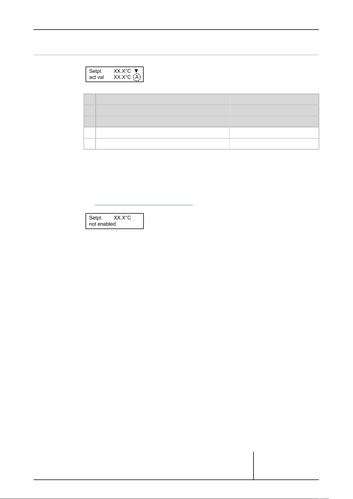
4.2 Status displays in the Info menu
→ Status display
Automatic mode – internal control Static display
A
Manual mode – control value is specified fixed via display Static display
H
SLAVE mode – control value is specified externally Static display
S
Priority 1 fault Alternating with standard display
F
Priority 2 warning Alternating with standard display
W
Further messages in the second line
- No release
Page 29 / 107
- Error messages in clear text (alternating with actual value)
See Error messages and warnings , Page 96
→ Text message
Operating instructions – Güntner Motor Management GMM step V_3.0
© Güntner GmbH & Co. KG
Page 30

4.3 Operation
Page 30 / 107
Cancel and return to INFO menu
Enter key for function selection; change to EDIT mode and value acceptance
Right arrow for moving to the next menu level.
Left arrow for moving to the previous menu level.
Up/down arrow for scrolling through the menu level.
1. Use this key to move from the INFO menu to the Operating menu.
2. Use this key to return to the INFO menu at any time.
Operating instructions – Güntner Motor Management GMM step V_3.0
© Güntner GmbH & Co. KG
Page 31
4.4 Edit mode
This mode is required to change values (setpoints, for example).
Select menu option you want
(top line)
Change to menu option
Change to writing mode
(cursor flashes)
Page 31 / 107
Decimal point selection
(cursor flashes)
Change value
New value acceptance
Operating instructions – Güntner Motor Management GMM step V_3.0
© Güntner GmbH & Co. KG
Page 32

4.5 Selection mode
This mode is required to select functions (language, for example).
Select menu option you want
("Language", for example, top line)
Change to the menu option
→ The function/language currently set
is marked with an *asterisk*.
Set target language by scrolling to the
top line
→ selected function/language in top line
Page 32 / 107
Accept function/language.
→ selected language is marked with an
*asterisk*.
Operating instructions – Güntner Motor Management GMM step V_3.0
© Güntner GmbH & Co. KG
Page 33

4.6 Configuration
4.6.1 Configuration table
The GMM step is configured with an appropriate number of potential-free contacts. Their assignments will differ depending on the configuration.
Page 33 / 107
GRCS.1
GMM step basic
GMM step
professional
I/O Signal 2 steps 3 steps 4 steps 2‑9 steps
DI1 24V Enable
DI2 24V No function / External error / External manual mode
DI3 24V Setpoint switchover or heating/cooling
AI1 4..20mA Pressure / Slave
AI2 4..20mA/KTY Pressure / Temperature / Slave
AI3 KTY Temperature
AI4 0..10V Slave
AO1 0..10V Control value
AO2 0..10V Subcooler
DO1 Relay
DO2 Relay
DO3 Relay
Fan 1 /
Group A
Fan 2 /
Group B
- Fan 3 /
Fan 1 /
Group A
Fan 2 /
Group B
Group C
Fan 1 /
Group A
Fan 2 /
Group B
Fan 3 /
Group C
Alarms priority 1
Alarms priority 2
Thermocontact reset
DO4 Relay - -
GIOD.1
DO1 Relay - - -
DO2 Relay - - -
DO3 Relay - - -
DO4 Relay - - -
DO5 Relay - - -
DO6 Relay - - -
DO7 Relay - - -
Table: Configuration table
Fan 4 /
Group D
Threshold value /
Fan 9 / Group I
Fan 1 /
Group A
Fan 2 /
Group B
Fan 3 /
Group C
Fan 4 /
Group D
Fan 5 /
Group E
Fan 6 /
Group F
Fan 7 /
Group G
Operating instructions – Güntner Motor Management GMM step V_3.0
© Güntner GmbH & Co. KG
Page 34

Page 34 / 107
GMM step basic
GMM step
professional
I/O Signal 2 steps 3 steps 4 steps 2‑9 steps
DO8 Relay - - -
DI1 24V - - -
DI2 24V - - -
DI3 24V - - -
DI4 24V - - -
DI5 24V - - -
DI6 24V - - -
DI7 24V - - -
Fan 8 /
Group H
Fan 1 /
Group A OK *1)
Fan 2 /
Group B OK *1)
Fan 3 /
Group C OK *1)
Fan 4 /
Group D OK *1)
Fan 5 /
Group E OK *1)
Fan 6 /
Group F OK *1)
Fan 7 /
Group G OK *1)
DI8 24V - - -
DI9 24V - - -
DI10 24V - - - -
DI11 24V - - - -
DI12 24V - - - -
DI13 24V - - - -
DI14 24V - - - -
DI15 24V - - - -
DI16 24V - - - Remote ac-
Group H OK *1)
Group I OK *1)
knowledgement
Table: Configuration table
*1) 24V
0V / open
= Fan / group n OK
= Fan / group n faulty
The GMM step professional variant requires additional hardware (GIOD.1, BAAN no.
5204183).
Fan 8 /
Fan 9 /
Operating instructions – Güntner Motor Management GMM step V_3.0
© Güntner GmbH & Co. KG
Page 35

4.6.2 Command outputs
Fan / fan group:
This output switches one step to control a fan or fan group. The output is closed when the
threshold for that step is exceeded. Two-way contact x1/x4 on the GRCS is closed while the
output is active. The closer contact x3/x4 on the GIOD is closed while the output is active.
Alarm fault (only GMM step professional):
All messages on the “Alarm fault” output refer to malfunctions resulting in complete failure
and standstill of the heat exchanger.
In an alarm situation, contact 11/12 is closed.
Alarm warning (only GMM step professional):
All messages on the “Alarm warning” output refer to events that do not result in complete failure of the heat exchanger. They warn that operation of the heat exchanger is impaired.
Contact 21/22 is closed when a warning is issued.
Threshold value:
In the Threshold function, exceeding the configured threshold values is signalled at this output.
See Threshold value, Page 51
Thermocontact reset
This output is activated for a period of two seconds when:
Page 35 / 107
a) The thermocontact reset function is activated and a fault is present for one output
See Thermocontact reset, Page 68
b) A remote acknowledgement is made via digital input DI16 on the GIOD
Operating instructions – Güntner Motor Management GMM step V_3.0
© Güntner GmbH & Co. KG
Page 36

4.7 Control inputs
The control inputs are designed as a low-voltage connection and are connected via a potential-free contact (relay, contactor contact, switch etc.). The potential-free contact must be
switched between the terminals +24V and the DI1 or DI2 or DI3 control input. The function is
activated when the contact is closed.
4.7.1 Enabling of GMM step
Fans are enabled via terminal DI1 (enable). Their speed then depends on the control value. If
enable is not switched, the fans will be disabled (speed = 0).
If they are not to be enabled externally, terminal DI1 must be jumpered.
This enabling jumper is always installed in the factory.
Page 36 / 107
Connection of external enable contact +24V – DI1
ADVICE
Under no circumstances may the controller be disabled by interrupting the supply voltage! Continuously switching the supply voltage can damage the controller and such damage is not covered by
the warranty!
Enable is not required in "Manual" mode.
See Manual mode, Page 56
Operating instructions – Güntner Motor Management GMM step V_3.0
© Güntner GmbH & Co. KG
Page 37

4.7.2 External fault/External manual mode
An external fault report can be connected via terminal DI2 . This function first has to be enabled in the IO menu.
The default is for it to be disabled.
Connection to +24V (high) signifies that there is currently NO fault pending (see Digital inputs,
Page 82). An open input or one switched to 0V signifies a fault. The source of this report
may be for example the output of an auxiliary contact on a circuit breaker.
Each fault signalled here is recorded in the alarm history. An active fault also generates a priority2 alarm message, which may also be signalled at the fault message output.
Alternatively, this input can be used to activate manual mode (see Digital inputs, Page 82).
Connection to +24V (high) signifies in this case that the manual mode control value set previously is output.
The input can also be assigned "no function".
4.7.3 Switching to 2nd setpoint (or between heating and cooling mode)
Setpoint switchover:
This function enables the switchover between two setpoints, which serve as controlling input
values. The switchover is made by connecting the "DI3" input.
If this terminal is blank, Setpoint 1 is always active. Ex works, this connection is blank (open).
Page 37 / 107
If this function is activated in the Service menu, the control mode can be switched over between heating and cooling. (Cooling and heat pump operation, for example)
The second setpoint and the second setpoint displacement are switched over with the DI3 input.
Operating instructions – Güntner Motor Management GMM step V_3.0
© Güntner GmbH & Co. KG
Page 38

4.7.4 Control inputs on the GIOD
4.7.4.1 Fault report inputs
4.7.4.2 Remote acknowledgement
The digital inputs of the GIOD can be used to register fault reports from the fan steps.
Fault reports from the thermocontact evaluation are usually registered here.
The number of fault report inputs must be configured during the commissioning process.
Connecting the input to +24V signifies: fan / fan group OK
An open input or connection to 0V signifies: fan / fan group faulty
Fault reports are assigned to the GIOD inputs DI1 up to at most DI9.
A manual thermocontact reset can be carried out via the GIOD.
While there is an active fault message, a change of level from low to high (0V to +24V) effects a single thermocontact reset.
Page 38 / 107
Operating instructions – Güntner Motor Management GMM step V_3.0
© Güntner GmbH & Co. KG
Page 39

4.8 Analogue inputs
The GMM has four sensor inputs:
Input AI1 Current input 4-20mA
Input AI2 switchable 4-20mA or impedance sensor GTF210
Input AI3 Impedance sensor GTF210
Input AI4 Voltage source 0-10V DC
The various ways of using inputs and how to connect them in each case are described below.
4.8.1 Connecting a pressure sensor to AI1/AI2
One or two (two-wire) sensors can be connected:
= Common supply voltage (GSW4003.1: brown(1), GSW4003:brown(1))
+24V
= 4-20mA signal from sensor 1 (GSW4003.1: blue(3), GSW4003: green(2))
AI1
Page 39 / 107
= 4-20mA signal from sensor 2 (GSW4003.1: blue(3), GSW4003: green(2))
AI2
The connected pressure sensors must be configured in the hardware configuration.
When two sensors are used the larger signal is always processed by the control unit as the
actual value (max. selection)
ADVICE
Three-wire sensors with a 4-20 mA signal output can also be connected, but these then require an
additional chassis potential. You can tap this from the GND terminal.
Important for pressure sensors: Do not install the sensor in the immediate vicinity of the
compressor to protect it from large pressure impacts and vibrations. It should be installed
as close to the condenser inlet as possible.
Pressure transmitter connection
Operating instructions – Güntner Motor Management GMM step V_3.0
© Güntner GmbH & Co. KG
Page 40

4.8.2 External power signal connection to AI1/AI2
The AI1 or AI2 inputs can also be used to control the controller in SLAVE operation.
To do this, this input must be defined as a control value slave in the I/O configuration.
The 4..20mA input signal is scaled 0-100% to a control signal and passed on to the fans.
A setpoint can also, for example, be specified externally via the AI1 or AI2 inputs.
Up to two power signals (4-20mA) can be connected to the AI1 and AI2 analogue inputs.
GND = Reference point (–).
AI1 = Current input (+) 4..20mA
AI2 = Current input (+) 4..20mA
ADVICE
Make sure the current source polarity is correct!
Page 40 / 107
Power source connection
For current inputs, note that currents of less than 2.4mA or greater than 22mA will provoke a
sensor fault display and corresponding message.
Operating instructions – Güntner Motor Management GMM step V_3.0
© Güntner GmbH & Co. KG
Page 41

4.8.3 Connecting a passive temperature sensor on AI2
The I/O configuration enables you to switch analogue input AI2 between current input and
passive temperature sensor.
See Switchover input AI2, Page 80
In this case it is switched in the same way as input AI3
4.8.4 Connecting a temperature sensor on AI3
A temperature sensor is connected on the terminals
GND
AI3
There is no particular sequence for the cores.
The Güntner GTF210 temperature sensor is used in the range -30°C to +70°C. Please contact us for other temperature ranges.
= Earth
= Signal input
Page 41 / 107
Temperature sensor connection
To test a temperature sensor that may be defective, disconnect it from the controller and measure the impedance of the sensor (with an ohmmeter or multimeter). On the GTF210 , the impedance should be between 1.04 kΩ (-50°C) and 3.27kΩ (+100°C). You can use the table below to check whether the sensor has the correct impedance at a known temperature.
Impedance Temperature Impedance Temperature
1040Ω -50°C 2075Ω 30°C
1095Ω -45°C 2152Ω 35°C
1150Ω -40°C 2230Ω 40°C
1207Ω -35°C 2309Ω 45°C
1266Ω -30°C 2390Ω 50°C
1325Ω -25°C 2472Ω 55°C
1387Ω -20°C 2555Ω 60°C
1449Ω -15°C 2640Ω 65°C
1513Ω -10°C 2727Ω 70°C
1579Ω -5°C 2814Ω 75°C
Table: Temperature / Impedance
Operating instructions – Güntner Motor Management GMM step V_3.0
© Güntner GmbH & Co. KG
Page 42

Impedance Temperature Impedance Temperature
1645Ω 0°C 2903Ω 80°C
1713Ω 5°C 2994Ω 85°C
1783Ω 10°C 3086Ω 90°C
1854Ω 15°C 3179Ω 95°C
1926Ω 20°C 3274Ω 100°C
2000Ω 25°C 3370Ω 105°C
Table: Temperature / Impedance
4.8.5 0-10V voltage signal connection to AI4
A standard signal (0-10V) is connected on the following terminals
= Earth (negative)
GND
AI4 = Signal input 0-10V DC (max. 12V DC).
Make sure the polarity is correct (earth to GND, signal to AI4)!
Page 42 / 107
The 0-10V input is mostly used to operate the controller in SLAVE mode. To do this, this input must be defined as a slave input in the I/O configuration. The 0-10V input signal is scaled
0-100% in a control signal and passed on to the fans.
As an alternative, you can also connect a GHP manual potentiometer as a remote control. The
connecting terminals on the GHP are labelled with either 1/2/3 or x/-/Y :
+ or 3 on +24V
– or 1 on GND
Y or 2 on AI4
You can then use the speed controller purely as a speed adjuster and specify the fan speed
yourself manually.
0-10V standard signal connection
Operating instructions – Güntner Motor Management GMM step V_3.0
© Güntner GmbH & Co. KG
Page 43

4.9 Analogue outputs
The control unit has 2 analogue outputs with 0..10V output voltage.
Analogue outputs
The AO1 output issues the control signal (0..100%) scaled to 0..10V .
Output AO2 issues the control signal for a subcooler, if this function is activated. 0..10V corresponds here with a control value of 0..100%.
Page 43 / 107
See Subcooler function, Page 72
Operating instructions – Güntner Motor Management GMM step V_3.0
© Güntner GmbH & Co. KG
Page 44

4.10 Operating menu
Structure of basic menu
Page 44 / 107
Operating instructions – Güntner Motor Management GMM step V_3.0
© Güntner GmbH & Co. KG
Page 45

4.10.1 Actual values
The actual input signals and control values are shown here.
4.10.1.1 Input current values
Different values can be displayed when the Current values menu option is opened. The measured pressure, the temperature or the 0-10V control signal is displayed first. The value shown
depends on the cooler type (condenser or recirculating cooler) and the operating mode (automatic or slave).
Page 45 / 107
Condenser
Condenser
Drycooler
Slave
4.10.1.2 Ambient temperature
The current ambient temperature is shown.
4.10.1.3 Control value
The control value of the controller delivered to the fans is displayed in percent.
No refrigerant
Refrigerant selected
via 0..10V or 4..20mA
Operating instructions – Güntner Motor Management GMM step V_3.0
© Güntner GmbH & Co. KG
Page 46

4.10.1.4 Air volume
The average control value of all fans is shown here as a percentage.
4.10.1.5 Steps
Here the system displays the current status of the step (on or off) and the corresponding digital output.
The length of the list depends on the number of configured steps.
Menu: Individual fan control
Page 46 / 107
Menu: Fan group control
Operating instructions – Güntner Motor Management GMM step V_3.0
© Güntner GmbH & Co. KG
Page 47

4.10.2 Status
The operating statuses and software/hardware versions are displayed here.
4.10.2.1 Operating mode
This shows the current operating mode.
There are:
Page 47 / 107
Setpoint 1 active See Auto internal, Page 63
Setpoint 2 active See Auto internal, Page 63
Setpoint 1 active See Auto external , Page 63
Setpoint 2 active See Auto external , Page 63
Setpoint 1 active
Internal
control
Auto int. 1
Auto int. 2
Auto ext. 1
Auto ext. 2
Auto ext. bus1
via GCM*
Auto ext. bus 2
Setpoint 2 active
via GCM*
Slave ext.
Control value via
0...10V
Slave
Slave ext. bus
or 4-20mA
Control value via GCM*See Slave external BUS, Page 64
Manual mode Manual mode
* GCM = Güntner Communication Module
See Auto external BUS, Page 64
See Auto external BUS, Page 64
See Slave external , Page 64
See Manual mode, Page 56
For a precise description of the operating modes see section Operating mode, Page 63
Operating instructions – Güntner Motor Management GMM step V_3.0
© Güntner GmbH & Co. KG
Page 48

4.10.2.2 Mode
Set heating or cooling mode display.
4.10.2.3 External release - Status
Controller on connection DI1 enabled "OK" or not "None"
4.10.2.4 GMM type
The configured type is shown here. If a GIOD expansion module is attached, this shows GMM
step professional (otherwise, GMM step basic).
Page 48 / 107
4.10.2.5 Number of steps
The number of steps is displayed here.
4.10.2.6 Number of error inputs
The number of error inputs is displayed here.
4.10.2.7 Fancycling
This shows whether fancycling is currently on or off
Operating instructions – Güntner Motor Management GMM step V_3.0
© Güntner GmbH & Co. KG
Page 49

4.10.2.8 Heat exchanger
The heat exchanger type is displayed here.
4.10.2.9 Refrigerant
If a condenser has been selected as the heat exchanger, the selected refrigerant is displayed
here. If no refrigerant has been selected, “bar” is displayed.
4.10.2.10 Hardware and software versions
This shows information about the current hardware and software versions of the GMM.
Page 49 / 107
GRCS = step controller
H = hardware version
S = software version
4.10.2.11 Bus module
This display provides information on the module type, firmware version and the address of the
GCM bus module, when it is connected.
4.10.2.12 Threshold status
This shows whether a configured threshold value has been exceeded or is below.
See Threshold value, Page 51
4.10.2.13 Emergency setting status
Operating instructions – Güntner Motor Management GMM step V_3.0
This shows whether a configured emergency setting is currently active.
© Güntner GmbH & Co. KG
Page 50

4.10.2.14 GHM Controller
If a GHM spray controller is connected, this will be shown here.
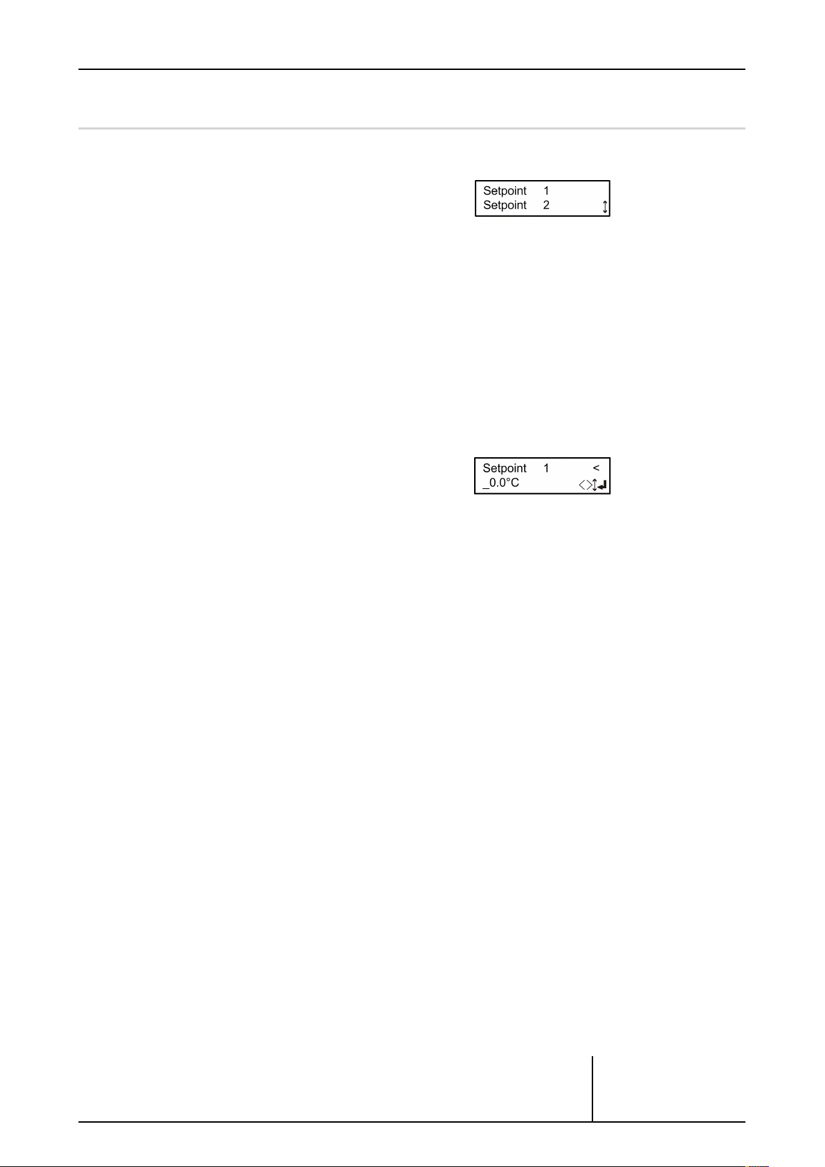
4.10.3 Setpoints
The setpoints can be set here.
The setpoint is the value (pressure, temperature or voltage) used as the reference for the control.
Page 50 / 107
4.10.3.1 Setpoint 1
The current setpoint is displayed when the Setpoint 1 menu option is opened. What is displayed as the setpoint depends on the actual input value defined (voltage, temperature or
pressure) and the operating mode (internal control or slave operation). As an example, setpoint 1 is displayed as the temperature.
Press the enter key to enter EDIT mode.
Use the left/right arrow keys to select the write position. Use the up/down arrow keys to edit
the value at the selected position.
The minimum and maximum adjustment range is:
The values are entered to one decimal place. Press the enter key to accept the set value.
4.10.3.2 Setpoint 2
If 2 setpoints are defined in the SERVICE menu, a second setpoint is set here. This can be activated via digital input DI3. Setpoint 2 is programmed the same way as setpoint 1.
Set current value Set operating mode Setpoint display
Temperature Control -30.0 - 100.0 °C
Pressure Control 0.0 - 50.0 bar
Volt Control 0.0 - 10.0 V
Operating instructions – Güntner Motor Management GMM step V_3.0
© Güntner GmbH & Co. KG
Page 51

4.10.3.3 Threshold value
This function is available only for GMM step professional with from two to eight steps.
Here you can set the threshold values, violation of which will activate the threshold function.
Appropriate threshold values for the configured system are offered in the Service menu (see
Threshold value, Page 73).
The threshold relay DO4 trips when the threshold value is exceeded.
Page 51 / 107
Operating instructions – Güntner Motor Management GMM step V_3.0
© Güntner GmbH & Co. KG
Page 52

4.10.4 Alerts
The last 85 alerts can be called up here.
4.10.4.1 Alert memory
The GMM has an alert memory that can accommodate up to 85 incident report, turn-on
and reset times stored consecutively (cyclically). These incident reports consist of the fault
and the time stamp, comprising the date and time when the fault occurred. For a list of error messages and warnings see Error messages and warnings , Page 96.
When the alert memory is selected, the display shows the last fault that occurred.
Use the “down” arrow key to display older faults.
Page 52 / 107
Operating instructions – Güntner Motor Management GMM step V_3.0
© Güntner GmbH & Co. KG
Page 53

4.10.5 Language
The menu language can be selected here.
4.10.5.1 Language selection
3 languages can be selected in the Language selection menu. The selected language is
marked with an *asterisk*.
Page 53 / 107
Operating instructions – Güntner Motor Management GMM step V_3.0
© Güntner GmbH & Co. KG
Page 54

4.10.6 Time
The time can be selected here.
4.10.6.1 Time setting
The set time is displayed and changed where required in the 24-hour clock.
The time is used to enter the alarm times in the alarm memory and for all timer functions.
Page 54 / 107
Operating instructions – Güntner Motor Management GMM step V_3.0
© Güntner GmbH & Co. KG
Page 55

4.10.7 Date
4.10.7.1 Set date
Page 55 / 107
The date can be set here.
The date is used to enter the alarm times in the alarm memory and for all timer functions.
Operating instructions – Güntner Motor Management GMM step V_3.0
© Güntner GmbH & Co. KG
Page 56

4.10.8 Manual mode
Manual mode is used to start up the heat exchanger fans by hand.
Manual mode does not depend on DI1 enabling.
Manual mode has the highest priority and switches off all other control
types.
The fact that manual mode is active is recorded permanently. In other
words, it will still be active after you have switched the system off and back
on.
Manual mode can also be activated via digital input 2. The digital input has to be configured
accordingly for this purpose in the Service menu (see Digital inputs, Page 82 or External
fault/External manual mode, Page 37).
If the input is configured and connected with +24 Volt, the previously defined manual mode
control value is output.
4.10.8.1 Manual mode settings
In order to set manual mode you first need to select the desired type of manual operation
from the “Mode” menu.
Page 56 / 107
Manual mode off:
Manual mode is inactive.
Manual mode control value:
Manual mode has been activated, the control values are prescribed by a parameter.
Manual mode fans:
Manual mode has been activated, each fan or fan group can be specifically switched on or off.
Manual mode settings:
When manual mode is active, this enables you to modify either the manual control value or
the state of the relevant output.
Operating instructions – Güntner Motor Management GMM step V_3.0
© Güntner GmbH & Co. KG
Page 57

Page 57 / 107
ADVICE
The settings for manual mode are fail-safe. After switching the GMM step off and back on, the most
recently specified manual mode is reactivated and again has higher priority than all other control
types.
Operating instructions – Güntner Motor Management GMM step V_3.0
© Güntner GmbH & Co. KG
Page 58

4.11 Service
The Service menu is accessible only with the correct password, which is the
first thing you are asked for.
The password is 3795.
Once the password has been accepted, the Service menu appears.
The password is valid for 15 minutes and will not be requested again during
this time.
Password prompt Service menu set-up
Page 58 / 107
Operating instructions – Güntner Motor Management GMM step V_3.0
© Güntner GmbH & Co. KG
Page 59

4.11.1 Control parameters
In this menu you configure the control parameters of the digital PID controller (proportional, integral, derivative controller).
4.11.1.1 Control parameters Kp, Ti and Td
Page 59 / 107
The Kp factor can be entered in a range from 0.1 to 100.0 to one decimal place. The Kp factor specifies the control amplification. It is the proportion of the control path following the input signal.
The Ti reset time changes the control value in the set time by the value specified by the proportional factor.
Example: With an unchanged control deviation (Xs) of 1K and Xp = 10 the control signal in Ti
= 25s is increased by 10%.
The delay time Td can be set in a range from 0 to 1000 seconds. The D part of the controller
does not react to the deviation but to the speed of change.
Operating instructions – Güntner Motor Management GMM step V_3.0
© Güntner GmbH & Co. KG
Page 60

4.11.1.2 Cooling/heating control parameter mode
Normally the GMM is used to cool liquids and refrigerants. With some applications a reversal of the function is required, i.e. liquids are warmed (e.g. with heat pumps). With the “Mode”
control parameter setting the control characteristics can be set to heating.
It is possible to change the mode (heating ext) via the DI3 input.
4.11.1.3 Base control value and Start control value control parameters
Page 60 / 107
The base control value function is used to set a minimum speed.
The start control value function is used to define a start point for issuing the control value.
Here are some setting examples:
Base
control
value
Start
control
value
Position
0% 0% Functions of, normal control 0%-100% with enable
10% 0% At least 10% control value is issued, when the enable is active
10% 5%
10% 10%
At least 10% control value is only then issued when the control
has reached 5% and the enable is due
The 10%-100% control value is only issued when the control
reaches 10%
The control value is 0% when the general value is under 5%.
0% 5%
The general value is issued from 5% control with given enable
(5%-100%).
Operating instructions – Güntner Motor Management GMM step V_3.0
© Güntner GmbH & Co. KG
Page 61

4.11.2 Heat exchanger
The heat exchanger type is selected here.
4.11.2.1 Heat exchanger type
The heat exchanger type is selected here.
The selected type is displayed with a*.
Page 61 / 107
→ Select with ENTER.
Operating instructions – Güntner Motor Management GMM step V_3.0
© Güntner GmbH & Co. KG
Page 62

4.11.3 Refrigerant
A refrigerant is selected here.
This menu option is not offered if a drycooler is defined with the heat exchanger.
4.11.3.1 Refrigerant selection
Page 62 / 107
In this menu option you can select whether
a refrigerant has been defined and whether
the display of reference and current values
with temperature should be converted accordingly, or whether no refrigerant has been
defined (bar) and the setpoints and current
values should be displayed as pressure.
The selected option is displayed with a*.
Operating instructions – Güntner Motor Management GMM step V_3.0
© Güntner GmbH & Co. KG
Page 63

4.11.4 Operating mode
The operating mode can be set in this mode.
The active mode is shown with a *.
4.11.4.1 Auto internal
In this mode, control is automatic on the basis of the setpoint defined internally. This setpoint
is entered in the Setpoints menu option.
Page 63 / 107
4.11.4.2 Auto external
In this mode, control is automatic on the basis of the setpoint defined externally by the analogue input. Which input delivers the setpoint and which the actual value is defined in the IO
configuration.
Operating instructions – Güntner Motor Management GMM step V_3.0
© Güntner GmbH & Co. KG
Page 64

4.11.4.3 Auto external BUS
In this mode the setpoint is specified via BUS.
A Güntner Communication Module (GCM module) is required for this operating mode.
4.11.4.4 Slave external
In this mode, there is no internal control. Instead the control value on the slave input is scaled
and forwarded directly to the fans. Which input is to be used as the slave input is defined in
the I/O configuration.
Page 64 / 107
4.11.4.5 Slave external BUS
Operating instructions – Güntner Motor Management GMM step V_3.0
In this mode the control value is specified via BUS.
A Güntner Communication Module (GCM module) is required for this operating mode.
© Güntner GmbH & Co. KG
Page 65

4.11.5 Bypass
The bypass function can be activated or deactivated in this service option. If
the function has been activated, the control value for bypass mode can be
set.
This function is used to maintain operation in the event of a fault in a GMM
component.
4.11.5.1 Software bypass (SW bypass)
In the event of a sensor failure, this configured control value will be output.
Default = 100%
Page 65 / 107
Operating instructions – Güntner Motor Management GMM step V_3.0
© Güntner GmbH & Co. KG
Page 66

4.11.5.2 GIOD bypass
This function is available only in GMM step professional.
If the GRCS.1 should fail, a configurable number of outputs on the GIOD.1 will be activated.
The number of outputs is set to zero by default.
Page 66 / 107
Operating instructions – Güntner Motor Management GMM step V_3.0
© Güntner GmbH & Co. KG
Page 67
4.11.6 Step parameters
Here you can modify the parameters of the step generator.
4.11.6.1 Fancycling
When fancycling is active, the running times of all the fans will be balanced.
This ensures that, on average, all the fans are subjected to the same load.
Page 67 / 107
With active fancycling there is NO 1:1 correlation between active steps and outputs.
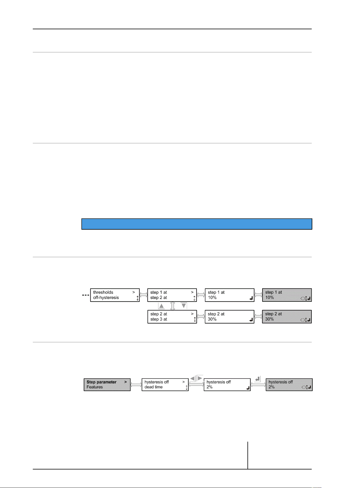
4.11.6.2 Threshold value
Here you can specify a threshold value for each step.
The step will then be switched active when the control value of the internal PID controller
reaches this threshold.
4.11.6.3 Off hysteresis
A hysteresis is defined to prevent a given step from being switched on and off too frequently.
This means that each stage switches off only when it reaches the corresponding threshold value minus the hysteresis.
ADVICE
Operating instructions – Güntner Motor Management GMM step V_3.0
© Güntner GmbH & Co. KG
Page 68

4.11.6.4 Dead time
This is the time until the next higher step is switched in.
This prevents a number of steps from being switched in simultaneously.
Switching the steps back down is carried out with no hold-off time.
4.11.6.5 Thermocontact reset
The thermocontacts of the fans are used to interrupt a self-maintaining actuation of the contactor.
An overheated fan is thus switched off. The thermocontact reset circuit can also be used to reactivate the self-maintaining function.
The thermocontact reset is a pulse of about two second duration and is output on digital output DO3 on the GRCS.
Page 68 / 107
ADVICE
The function can be set up in this menu.
A thermocontact reset pulse is emitted by default when the controller is first switched on and
one minute after any fault message.
Operating instructions – Güntner Motor Management GMM step V_3.0
© Güntner GmbH & Co. KG
Page 69

4.11.6.6 Running times
The active running times for each fan or fan group are established and can be displayed here.
These times are cumulated from the initial commissioning. Each active second for a fan or fan
group is recorded.
Among other things, the recorded running times of fans are used for the fancycling function,
to enable fan operation to be balanced.
You can clear the running times for individual fans or fan groups. This will be appropriate e.g.
when a fan has been replaced.
Resetting the controller to its factory or delivery settings does not clear the running times of
fans or fan groups.
A maximum of 65535 hours running can be recorded for each fan or fan group. This is relatively unrealistic,
but if this value is ever reached, the running times of all the fans and fan groups will be zeroed.
An entry will also be made in the alarm history.
Page 69 / 107
Menu: Individual fan control
Menu: Fan group control
Operating instructions – Güntner Motor Management GMM step V_3.0
© Güntner GmbH & Co. KG
Page 70

4.11.7 Features
The special functions, such as number of setpoints, the night limiter or setpoint displacement, or the subcooler function, can be selected in this service menu option.
4.11.7.1 Number of setpoints
Page 70 / 107
The number of setpoints is set here. The minimum number is 1 setpoint on which control is
performed. If 2 setpoints are selected, switchover is via digital input DI3. If the input is open,
setpoint 1 is used for control.
If the DI3 input is connected with +24V, setpoint 2 is used for control.
Two different setpoints can consequently be determined for summer and winter operation, for
example.
Operating instructions – Güntner Motor Management GMM step V_3.0
© Güntner GmbH & Co. KG
Page 71

4.11.7.2 Offset setpoint
It is beneficial in order to ensure the optimum energy operation to displace
the setpoint under certain circumstances, depending on the external temperature.
Setting the min. condensation temperature can cause rising external temperatures, so that the external temperature is above the setpoint. If the system is now only to be operated at partial load, raising the setpoint can save
energy on the fans. Without a displacement these fans would always be controlled with 100%, as the high external temperature (above the setpoint)
means this setpoint cannot be reached.
The temperatures Tmin external and Tmax external can be set in the menu. The range between Tmin external and Tmax external marks the range to be displaced into. The ∆T, which
defines the offset between the setpoint and the external temperature, must also be defined.
Example: Setpoint
In this example the setpoint must always be 5 K above the external temperature. The displacement therefore begins at 20.1°C external temperature. At this point the setpoint is displaced to 25.1°C. Tmin external and Tmax external limits mark the range in which the displacement works. In this example the setpoint is displaced at 20°C at the earliest, provided
the setpoint is low enough. The max. value where the setpoint can be displaced to is at 45°C
in this example.
∆T
Tmin external
Tmax external
Page 71 / 107
= 25°C
= 5 K
= 20°C
= 40°C
Operating instructions – Güntner Motor Management GMM step V_3.0
© Güntner GmbH & Co. KG
Page 72

4.11.7.3 Subcooler function
This function allows a separate EC fan to be operated as subcooler. The control value for the
subcooler fan (0..10V = 0..100%) is given via the "AO2" output to the fan.
This subcooler runs constantly, independent of the regulation of the control unit with the set
speed. It is activated like the regulated fans via the enable.
The subcooler function can be switched on and off in the functions menu.
The fan type used is selected in the selection menu.
Page 72 / 107
Operating instructions – Güntner Motor Management GMM step V_3.0
© Güntner GmbH & Co. KG
Page 73

4.11.7.4 External BUS module
These functions allow you to change the interface parameters of the connected bus module.
The following parameters can be changed for a Modbus RTU module:
Address: 1….247
Baud rate: 1200, 2400, 4800, 9600, 19200, 38400, 57600, 76800, 115200 Baud
Framing: 8,E,1 (8 Bit, even parity, 1 Stop Bit)
Page 73 / 107
8,N,1 (8 Bit, no parity, 1 Stop Bit)
8,N,2 (8 Bit, no parity, 2 Stop Bit)
8, O,1 (8 Bit, odd parity, 1 Stop Bit)
Only the fieldbus address can be changed for a Profibus (0….126); the baud rate is set automatically.
Turn off the power to GMM + bus module after every address change. Only then will the new parameters be accepted.
4.11.7.5 Threshold value
Using the threshold value function, the threshold value relay (digital output DO4, contact
41/44) can be tripped depending on various parameters.
The function must first be activated and pre-configured in the Service menu for this.
The respective threshold values can then be set in the Setpoints menu.
The function is deactivated by default.
ADVICE
Operating instructions – Güntner Motor Management GMM step V_3.0
© Güntner GmbH & Co. KG
Page 74

Page 74 / 107
Operating instructions – Güntner Motor Management GMM step V_3.0
© Güntner GmbH & Co. KG
Page 75

Page 75 / 107
YES/NO threshold value:
The function can be switched on or off here. Only when the function is switched on is this active and offered in the Setpoints menu.
Threshold value depends on:
What the function depends on can be configured here.
Depends on
control value:
The threshold value relay is tripped when the control value is greater than the configured
threshold value.
Depends on
actual value:
The threshold value relay is tripped when the actual value is greater than the configured
threshold value.
Depends on
control value + Ext. temp..:
The threshold value relay is tripped when the control value AND the external temperature are
greater than the configured threshold values.
Depends on
actual value + ext. temp.:
The threshold value relay is tripped when the actual value AND the external temperature are
greater than the configured threshold values.
Emergency control value Yes/No/Emergency control value:
The emergency control value is issued as a control value when the following conditions are
satisfied:
- Threshold value function is active
- Threshold value condition(s) exceeded
- Emergency control value function is active
- Emergency control value is greater than its calculated control value (e.g. with control operation or bypass value with sensor fault)
- Manual mode is not active
- External enable provided
The emergency control value can be reduced to an active night limiter if necessary.
Operating instructions – Güntner Motor Management GMM step V_3.0
© Güntner GmbH & Co. KG
Page 76
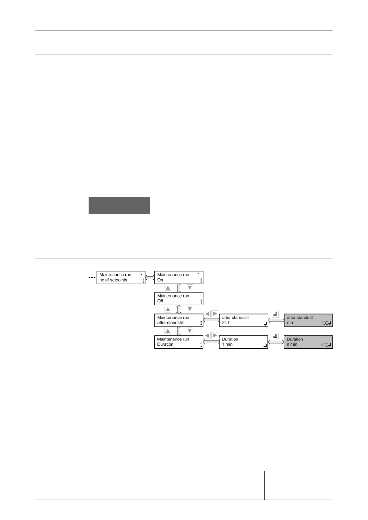
4.11.7.6 GHM Controller
When a GMM is coupled with a GHM spray via the CAN bus, this function has to be activated
for the GMM (master).
The GMM is then responsible for the control and monitoring of the GHM.
If the connection fails, an entry is made in the GMM alarm history (and that of the GHM).
If the GHM spray function is activated, this will be displayed in the status menu:
Page 76 / 107
If the function is corrupt (e.g. GHM is off), GHM-NOK will be displayed in the Info menu.
Furthermore, a priority 2 incident report is issued and an entry made in the alarm history.
4.11.7.7 Maintenance run
A maintenance run is activated in response to the length of time the fans have been stationary. Its purpose is to prevent them from becoming jammed.
Activation of a maintenance run after the configured standstill period depends on the following conditions being fulfilled:
a) Manual operation is deactivated
b) Control value of the PID controller = 0, i.e. no speed request
c) No fault pending
The controller does not need to be enabled, because the speed control is often enabled only
when cooling has been requested. Otherwise the maintenance cycle would effectively be disabled and a maintenance run would never happen.
Operating instructions – Güntner Motor Management GMM step V_3.0
© Güntner GmbH & Co. KG
Page 77

Page 77 / 107
If a speed request is made during a maintenance run , the maintenance process will be aborted and the controller will return to normal operation. In such cases, maintenance is considered to have been performed, because the fans have been in operation.
A maintenance run is carried out at full speed, but this will be reduced by an active night limit.
The following parameters can be set up:
“Maintenance run On/Off”:
Default = On
This is used to turn the function on or off.
“Maintenance run after standstill”:
Default: 24 hrs, min=1, max = 1000 hrs
If the fans have not been in operation at all during this configured period then a maintenance
run will be started.
“Duration of maintenance run ”:
Default =1 min, min = 1 min, max = 10 min
This is used to specify the duration of a maintenance run.
The Info menu display “Maintenance run” flashes while a maintenance cycle is in operation.
Status menu display: “Maintenance run in: nnn h”
This shows the remaining required stationary period before the next
maintenance cycle.
Operating instructions – Güntner Motor Management GMM step V_3.0
© Güntner GmbH & Co. KG
Page 78

4.11.8 I/O configuration
This menu option is used to configure the analogue and digital inputs and
outputs.
Selected functions can be assigned to the inputs and outputs.
4.11.8.1 Analogue inputs
The analogue inputs are measurement inputs for recording temperature or pressure values.
These inputs can also be used to prescribe control values (slave mode).
Terminals AI1 and AI2 are two current inputs (4-20mA).
Input AI2 can be switched over to serve as input for a temperature sensor.
Page 78 / 107
Terminal AI3 has an input for the GTF210 temperature sensor.
There is an input for 0-10 V DC on terminal AI4 .
Operating instructions – Güntner Motor Management GMM step V_3.0
© Güntner GmbH & Co. KG
Page 79

4.11.8.1.1 Current inputs AI1
Page 79 / 107
Actual value means that the current measurement is signalled on this input. With pressure
sensor GSW4003 this is the current corresponding to the pressure. Make sure that "Auto Int"
mode has been selected in the Operating mode menu. There is a special situation if both cur-
rent inputs are configured as the actual value. The current input delivering the greatest measurement signal is then selected (MAX selection). A Actual value of 0-25 bar or 0-40 bar can be
selected with the current input
Slave control value means that the control signal for the fans follows this input. With current
input this means that 4 mA generates a control signal of 0%, and 20mA input current a control signal of 100% on the fans. Make sure that the "Slave ext" mode has been selected in the
Operating mode menu.
Setpoint 1 means that setpoint 1 on which internal control is performed is specified via the
current input. The current input is scaled to the set actual value (see table Error messages
and warnings , Page 96). The origin of the actual value still has to be configured. Make sure
that the "Auto ext" mode has been selected in the Operating mode menu.
Setpoint 2 is offered only if the number of setpoints has been configured as 2 (see Number of
setpoints, Page 70). If setpoint 2 is configured, the same applies as described with Setpoint 1 .
No function is selected if this input is to be inactive.
The same essentially applies to current input 2 as to current input 1, except that there are still
two additional setting options.
Operating instructions – Güntner Motor Management GMM step V_3.0
© Güntner GmbH & Co. KG
Page 80

4.11.8.1.2 Switchover input AI2
Page 80 / 107
ADVICE
The Service menu enables you to adjust the temperature sensors by specifying an offset for the
configured temperature inputs AI2 and AI3.
The following functions exist in addition to the functions offered with input AI1:
act. val. temp.means that a temperature sensor with 4..20mA current output (-30°C to +70°C)
is connected on this current input. Function as described for actual value.
outside temp.means that a temperature sensor with 4..20mA current output (-50°C to +50°C)
is connected on this current input. This input is used exclusively for recording external temperature.
act val. GTF210 means that a GTF210 temperature sensor is connected to this input. Please
note! This function is only available with the corresponding software version.
Operating instructions – Güntner Motor Management GMM step V_3.0
© Güntner GmbH & Co. KG
Page 81

4.11.8.1.3 AI3 input temperature sensor
The Service menu enables you to adjust the temperature sensors by specifying an offset for the
configured temperature inputs AI2 and AI3.
act val GTF210 means that a GTF210 temperature sensor is connected to this input.
outside temp. means that a GTF210 temperature sensor is connected to this input to record
the external temperature. The measurement range is -30°C to +70°C. It is ensured that only 1
external temperature can be selected.
Page 81 / 107
ADVICE
No function is selected if this input is to be inactive.
4.11.8.1.4 0..10V AI4 input
act. val 0.10V means that the current value (0-10V) for the controller should be connected to
this input. Make sure that the mode “Auto Int” has been selected from the Operating mode
menu.
ctrl. val slavesignifies that the fans are addressed in response to the input signal (0-10V). The
characteristic curve is linear from 0-100%. A 10V signal corresponds to a control value of
100% for the fans. Make sure that the mode “Slave Ext” has been selected from the Operating
mode menu.
setpoint 2 is offered only if the number of setpoints has been configured as 2 (see Number of
setpoints, Page 70). If setpoint 2 is configured, the same applies as described for Setpoint 1 .
Operating instructions – Güntner Motor Management GMM step V_3.0
© Güntner GmbH & Co. KG
Page 82

4.11.8.2 Digital inputs
The digital inputs on terminals DI1, DI2 and DI3 are control inputs.
The inputs are active when they are connected to +24V . They can only be switched with potential-free contacts (e.g. relay contact).
Page 82 / 107
4.11.8.3 Analogue outputs
The analogue outputs can output a voltage of 0-10 V DC. Fixed functions are assigned to analogue outputs 1 and 2. Output 1 issues the control signal from 0-100% scaled as a 0-10V signal.
Output 2 issues the control signal for the subcooler, when the function is selected.
Operating instructions – Güntner Motor Management GMM step V_3.0
© Güntner GmbH & Co. KG
Page 83

4.11.8.4 Digital outputs
The digital outputs are relay contacts. Each output has a 250V/1A two-way contact. The alarm
outputs Prio 1 and Prio 2 are connected as failsafe contacts, i.e. the contact is closed when
there is no current.
Fixed functions are assigned to the digital outputs.
Page 83 / 107
For information about the function, see Configuration table, Page 33.
Operating instructions – Güntner Motor Management GMM step V_3.0
© Güntner GmbH & Co. KG
Page 84

4.11.9 SI/IP selection
The units system can be selected here.
4.11.9.1 SI/IP units system
Unit selection for pressure and temperature.
Page 84 / 107
International units →
Anglo-American units →
SI (Système international d´ unités)
IP (Imperial System)
The selected unit of measurement is marked with a *.
Operating instructions – Güntner Motor Management GMM step V_3.0
© Güntner GmbH & Co. KG
Page 85

4.11.10 Factory setting
The control can be reset to factory settings here.
4.11.10.1 Control reset (factory setting)
Page 85 / 107
ADVICE
Any changes made locally will be deleted. Factory commissioning values will be retained. The control functions and the bypass are reset to their default values.
See Factory setting, Page 94
Operating instructions – Güntner Motor Management GMM step V_3.0
© Güntner GmbH & Co. KG
Page 86

4.11.11 Delivery condition
The control can be reset to delivery condition here.
Commissioning is then not necessary.
4.11.11.1 Control reset (delivery condition)
Page 86 / 107
ADVICE
Any changes made locally and the commissioning values will be cleared. Once this function has
been completed, a completely new factory commissioning must be carried out.
Operating instructions – Güntner Motor Management GMM step V_3.0
© Güntner GmbH & Co. KG
Page 87

5 Faults and troubleshooting
5.1 General notes
Most faults that occur during commissioning are due to wiring faults or defective sensors. It
is only in the rarest of cases that the speed controller itself is defective. Check the following
points before ordering a replacement:
Status info menu:
• Is a fault displayed in the info menu? (You can always return to the Info menu by pressing X).
• If NO, then go to Test point 2.
• If the message “Equipment failure” is displayed, there is a fault pending at all outputs.
• For other error messages see Table Error messages and warnings , Page 96
TEST POINT 2:
Mains connection:
• Are all phases present?
Page 87 / 107
Sensor connection:
• Is the sensor connected correctly? Cf "Sensor connection" section
• Sensor OK? (Measure! Pressure: 4-20mA, Temp.: 1.2-2.7kΩ, default signal: 0-10V)
• Are the sensor cables laid in the immediate vicinity of the mains or motor cable? Consider
increasing the distance!
• Are the sensor cables shielded? If not – swap for shielded cables!
• Is the shielding applied unidirectionally on the controller?
Fuses:
• Is the fuse on the controller supply OK?
Operating instructions – Güntner Motor Management GMM step V_3.0
© Güntner GmbH & Co. KG
Page 88

6 Technical data
6.1 Component dimensions - Dimensions / Weight
Dimensions of GRCS.1
You will find the casing dimensions below. All dimensions are given in millimetres.
Page 88 / 107
Casing dimensions of GRCS.1
Weight:
ca. 340g
Operating instructions – Güntner Motor Management GMM step V_3.0
© Güntner GmbH & Co. KG
Page 89

Page 89 / 107
Dimensions of GIOD.1
You will find the casing dimensions below. All dimensions are given in millimetres.
Dimensions of casing of GIOD.1
Weight:
ca. 340g
Operating instructions – Güntner Motor Management GMM step V_3.0
© Güntner GmbH & Co. KG
Page 90

7 Electrical properties of the components
Electrical properties of GRCS.1
Min Type Max Unit
Voltage supply 21 24 30 V
Current consumption 80 250
Digital inputs
High level 15 24 30 V
Low level -3 0 5 V
Relay outputs
Voltage DC 24 30 V
Voltage AC 250 V
Page 90 / 107
1
mA
Current resistive load 24V DC/250V
AC
Current inductive load 24V
DC/250V AC
Switch cycles, mechanical 1*10
Switch cycles, electrical 1*10
6
5
1 A
1 A
Switching cycles
Switching cycles
Voltage input
Dielectric strength -24 30 V
Measuring range 0 12 V
Resolution 10 bit
Fault 1 %
Input resistor: 230 kΩ
Current input
Dielectric strength -24 30 V
Measuring range 0 21 mA
2
Resolution 10 bit
Fault 1 %
Input resistance
(without protective circuit)
Table: Electrical properties of GRCS.1
Operating instructions – Güntner Motor Management GMM step V_3.0
130
2
Ω
© Güntner GmbH & Co. KG
Page 91

Page 91 / 107
Min Type Max Unit
Voltage output
Voltage range 0 10 V
Load resistance >=100 kΩ
Resolution 10 bit
Fault 2.5 %
Short protection Yes
Potential separation No
Temperature input
Dielectric strength -24 30 V
Measuring range -30 100 °C
2
Resolution 10 bit
Precision 3 %
2
CAN bus
Dielectric strength -24 24 V
Transmission rate 125 kbit/s
Galvanic separation No
Table: Electrical properties of GRCS.1
1. The maximum current consumption includes supplying two attached pressure transponders and one attached temperature sensor.
2. Of the appropriate range
Operating instructions – Güntner Motor Management GMM step V_3.0
© Güntner GmbH & Co. KG
Page 92

Page 92 / 107
Electrical properties of GIOD.1
Min Type Max Unit
Power supply DC 21 24 30 V
Current consumption 100 250 mA
Digital inputs
High level 15 24 30 V
Low level -3 0 5 V
Relay outputs
Power supply DC 24 30 V
Voltage AC 250 V
Current resistive load 24V DC/250V AC 1 A
Current inductive load 24V DC/250V AC 1 A
Switch cycles, mechanical 1*10
Switch cycles, electrical 1*10
6
5
Switching cycles
Switching cycles
CAN bus
Dielectric strength -24 24 V
Transmission rate 125 kbit/s
Table: Electrical properties of GIOD.1
Operating instructions – Güntner Motor Management GMM step V_3.0
© Güntner GmbH & Co. KG
Page 93

8 External control value scaling
The dependencies of the external control value specs for the actual value regulations are explained in this table. A 0 ..10V external voltage can, for example, specify a temperature control
value. 0V is then equal to a temperature of 0°C and a voltage of 10V is equal to a control value
temperature of 100°C.
Page 93 / 107
Setpoint internal,
Current value
Pressure 0 ..25 bar
Temperature
0 .. 100°C
Voltage 0 .. 10V
Table: External control value scaling
depending on
current value
Pressure 0 .. 50 bar
Temperature
-30 .. 100°C
Voltage 0 .. 10V
Setpoint external
Current
4 .. 20mA
4mA = 0 bar
20mA = 50 bar
4mA = 0°C
20mA = 100°C
4mA = 0V
20mA = 10V
Setpoint external
Voltage
0 .. 10V
0V = 0 bar
10V = 5 bar
0V = 0°C
10V = 100°C
0V = 0V
10V = 10V
Operating instructions – Güntner Motor Management GMM step V_3.0
© Güntner GmbH & Co. KG
Page 94

9 Factory setting
Page 94 / 107
Dry cooler
Condenser
with refrigerant
Condenser
without refrigerant
Units SI IP SI IP SI IP
Language English
Setpoint 2 present No
Setpoint displacement No
Kp 10.0 10.0 10.0 10.0 20.0 20.0
Ti 25 sec. 25 sec. 25 sec. 25 sec. 40 sec. 40 sec.
Td 25 sec. 25 sec. 25 sec. 25 sec. 40 sec. 40 sec.
Base control value 0%
Start control value 0%
Setpoint 1 (2) 30°C 80°F
Threshold value No
Manual mode Off
Manual mode control
value
Setpoint displace-
ment
∆ T
40°C
(25°C CO2)
0%
5 K
104°F
(77°F CO2)
12.5 bar 181 psig
External temperature
displacement min.
External temperature
displacement max.
Depends on
external temperature
disp.
Subcooler function Off
Heating function Off
Fancycling On
Thresholds
of steps
Hold-off time 2 sec.
Off hysteresis Depending on the number of steps
Function of digital
input DI2
SW bypass 100%
0°C 32°F 0°C 32°F 0°C 32°F
50°C 122°F 50°C 122°F 50°C 122°F
Off
Defaults
(depending on the number of steps)
Ext. error Off
Table: Factory setting
Operating instructions – Güntner Motor Management GMM step V_3.0
© Güntner GmbH & Co. KG
Page 95

Page 95 / 107
Dry cooler
Condenser
with refrigerant
Condenser
without refrigerant
Units SI IP SI IP SI IP
GIOD bypass
(only with GMM step
prof.)
TC reset Automatic
Auto reset time 1 min
Maintenance run
function
Duration of mainte-
nance run
Maintenance run after
stop
Off
(0 steps)
On
1 min
24 h
Table: Factory setting
Operating instructions – Güntner Motor Management GMM step V_3.0
© Güntner GmbH & Co. KG
Page 96

10 Error messages and warnings
The table shows which signal relay (ALARM, PRIO 1 or PRIO 2) is tripped with which message
on the display.
* There is a pause of 5 seconds between the flash codes.
Page 96 / 107
Messages /
warnings
on the display
Display dark,
GMM step OFF
PRIO 1
GMM
step prof.
X X
PRIO 2
GMM
step prof.
Displayed where?
-
Explanation:
GMM has no supply voltage
Possible cause:
Main switch off, power pack has no power supply, power pack defective,
display defective
Measure:
Check the power supply and the fuses
No sensor selected Displayed where?
Info menu
Explanation:
No sensor activated in the I/O configuration
Possible cause:
Error in the I/O configuration
Measure:
Choose the appropriate assignment in the I/O configuration
not enabled
- –
Displayed where?
Info menu
Explanation:
DI1 (enable) not switched (open or 0V)
Possible cause:
Enable input DI1 on the GRCS is not switched; no enable from a high-
er-level controller; jumper between +24V and DI1 not in place
Measure:
Check the wiring; if appropriate check the signal from a higher-level con-
trol unit or controller
Table: Error messages / warnings on the display
Operating instructions – Güntner Motor Management GMM step V_3.0
© Güntner GmbH & Co. KG
Page 97

Page 97 / 107
Messages /
warnings
on the display
error EXT
error EXT OK
PRIO 1
GMM
step prof.
- X
- –
PRIO 2
GMM
step prof.
Displayed where?
Info menu + alarm memory
Explanation:
Input DI2 is configured as an external error input (see IO configuration /
digital input) and is not switched (open or 0 V)
Possible cause:
Thermocontact of a fan has triggered, one output is not OK (motor circuit
breaker has triggered), one fan output has been switched off, something
else is switched incorrectly
Measure:
Check whether the input is used as an error input, if appropriate deacti-
vate it in the IO configuration; check whether there is a fan fault; check
the circuit breaker; if this error occurs frequently the fan may be defective
and should be replaced
Displayed where?
Alarm memory
Explanation:
The error status has been resolved, input DI2 is switched (+24V)
Possible cause:
The thermocontact of a fan has closed again; an output is OK again; cir-
cuit breaker has been switched on. Some other fault message has been
resolved.
Measure:
None required
Setpoint 2
Sensor fault 1
- -
- X
Table: Error messages / warnings on the display
Displayed where?
Info menu
Explanation:
Control is on setpoint2, DI3 is connected (+24V)
Possible cause:
This is generally due to a specific action from the customer interface
Measure:
None required
Displayed where?
Info menu + alarm memory
Explanation:
The sensor on input AI1 is defective or the signal is out of range (4 …
20mA).
Possible cause:
Cable break, sensor not connected or defective
Measure:
Check the I/O configuration; check the connections and wiring; check the
input current, which must lie in the range 4 to 20mA, values below 2mA
will trigger the fault; replace the sensors
Operating instructions – Güntner Motor Management GMM step V_3.0
© Güntner GmbH & Co. KG
Page 98

Page 98 / 107
Messages /
warnings
on the display
Sensor fault 2
Sensor fault 3
PRIO 1
GMM
step prof.
- X
- X
PRIO 2
GMM
step prof.
Displayed where?
Info menu + alarm memory
Explanation:
The sensor on the switchable input AI2 is defective or the signal is out of
range (4 … 20mA or KTY).
Possible cause:
Cable break, sensor not connected or defective
Measure:
Check the I/O configuration; check the connections and wiring; check the
input current, which must lie in the range 4 to 20mA, values below 2mA
will trigger the fault; replace the sensors, if a KTY sensor is connected,
check the value of the resistance
Displayed where?
Info menu + alarm memory
Explanation:
The sensor on input AI3 is defective or the signal is out of range (KTY).
Possible cause:
Cable break, sensor not connected or defective
Measure:
Check the I/O configuration; check the connections and wiring; replace
the sensors
Sensor fault 4
GIOD NOK
- X
X -
Displayed where?
Info menu + alarm memory
Explanation:
The signal is out of range (0…10V)
Possible cause:
Voltage is higher than 12V
Measure:
Check the I/O configuration; check the voltage of the power source, which
must lie between 0 and 10V. You may have +24V connected to this in-
put.
Displayed where?
Info menu + alarm memory
Explanation:
The GIOD expansion module has a fault status.
Possible cause:
No communication to GIOD, CAN connection down (cable not OK or not
plugged in, GIOD without power or defective, the rotary code switch on the
GIOD is not set to address1
Measure:
Check that the GIOD is receiving power; check the CAN connection be-
tween the GRCS controller and the GIOD, it may be missing or plugged in-
correctly; check the cable connection; set the rotary node ID switch on the
GIOD to address1 and switch the GMM step off and back on
Table: Error messages / warnings on the display
Operating instructions – Güntner Motor Management GMM step V_3.0
© Güntner GmbH & Co. KG
Page 99

Page 99 / 107
Messages /
warnings
on the display
GIOD OK
GIOD PRE_OPERA
PRIO 1
GMM
step prof.
- -
- -
PRIO 2
GMM
step prof.
Displayed where?
Alarm memory
Explanation:
The GIOD expansion module has started operation correctly.
Possible cause:
OK message after switching on the power supply to GMM step or after
GIOD has successfully logged itself on afresh
Measure:
None required
Displayed where?
Alarm memory
Explanation:
The GIOD expansion module has taken on CANopen status
PRE_OPERATIONAL.
Possible cause:
This is a CANopen-specific reaction from the GIOD caused by incorrect or
missing communication
Measure:
Usually no measures are necessary. If this message occurs frequently you
may have a serious disruption of the CAN connection.
GIOD REBOOT
GIOD STOPPED
- -
- -
Displayed where?
Alarm memory
Explanation:
Because of a reboot, the GIOD expansion module has taken on CANopen
status PRE_OPERATIONAL.
Possible cause:
This is a CANopen-specific reaction from the GIOD caused by powering on
or a CAN error. The GIOD goes operational automatically.
Measure:
Usually no measures are necessary. If this message occurs frequently you
may have a serious disruption of the CAN connection.
Displayed where?
Alarm memory
Explanation:
The GIOD expansion module has taken on CANopen status STOPPED.
Possible cause:
This is a CANopen-specific status that occurs only by specific command
of the CAN master. It does not generally occur on GMM step.
Measure:
Usually no measures are necessary. If this message occurs frequently you
may have a serious disruption of the CAN connection.
Table: Error messages / warnings on the display
Operating instructions – Güntner Motor Management GMM step V_3.0
© Güntner GmbH & Co. KG
Page 100

Page 100 / 107
Messages /
warnings
on the display
Fan n NOK
/ F-group n NOK
Fan n OK
/ F-group n OK
PRIO 1
GMM
step prof.
- -
PRIO 2
GMM
step prof.
X
Displayed where?
Info menu + alarm memory
Explanation:
There is an error report for fann or fan groupn. The error input on GIOD
is not switched (open or 0V).
Possible cause:
One fan or group is not OK; the thermocontact of a fan or a motor circuit
breaker has triggered; 24V for error messages is faulty
Measure:
Check whether there is a fan fault; check the circuit breakers; if this error
occurs frequently the fan may be defective and should be replaced
Displayed where?
Alarm memory
Explanation:
Error message for fan or groupn cancelled. The error input on GIOD is
switched (+24V).
Possible cause:
One fan or group is OK again; the thermocontact of a fan has closed
again; a circuit breaker has been switched on; reaction following a manu-
al or automatic thermocontact reset; OK message after switching on the
power supply to the GMM step
Measure:
None required
Unit fault
X X
Table: Error messages / warnings on the display
Displayed where?
Info menu + alarm memory
Explanation:
A fault message is pending at all outputs
Possible cause:
Malfunction of all the outputs
Measure:
Check the power supply to the fans and all the motor circuit breakers.
Operating instructions – Güntner Motor Management GMM step V_3.0
© Güntner GmbH & Co. KG
 Loading...