


Instruction Manual
MB_2015_PAS with PAS for Mercedes Benz
1

INDEX
Specifications
1. Main Spec. ---------------------------------------
2. Diagram ------------------------------------------
3. Components -------------------------------------
4. Components (Option) ---------------------------
5. Exterior -------------------------------------------
Settings
1. Dip Switch ---------------------------------------
2. ParkingàDrive ----------------------------------
3. Original button ---------------------------------
4. OSD Menu --------------------------------------
Installation
3
4
5
6
7
8
9
10
12
1. Diagram -----------------------------------------
2. LVDS Connection -------------------------------
3. CAN Connection --------------------------------
Caution
1. FQA -----------------------------------------
2. Caution ----------------------------------------
GU Electronic
17
18
19
20
20
2

Specification
1. Main spec.
1-1 Input Spec. (MULTI VIDEO INTERFACE)
- 1 x Analog RGB Input (Navigation System output)
- 1 x CVBS(REAR CAMERA) Input. (Rear camera source)
- 1 x CVBS(FRONT CAMERA) Input. (Front camera source)
- 1 x LVDS Input. (Car Command System)
- 1 x HDMI Input. (Car Command System)
1-2 Output Spec.
- 1 x LCD Output (LCD Operation)
1-3 Power Spec.
- Input Power : 8VDC ~ 24VDC
- Consumption Power : 12Watt, Max
1-4 Switch Input mode
- Possible to switch input mode through original button (p. 10)
2. Features
- Easy installation with Plug&Play power/LVDS cable
- Display dynamic PAS(Parking assistance system) with PDC
- Capacitive touch screen with frame (option – Refer to P.7)
GU Electronic
3
Specification
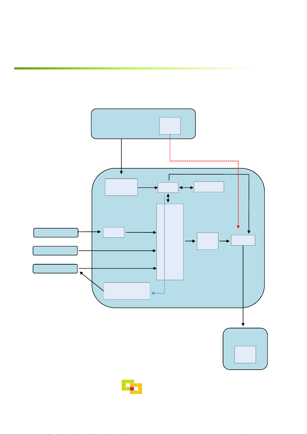
3. Diagram
INTERFACE
DIGITAL RGB
RGB+Syn
CAR
COMMAND
SYSTEM
CAN
CAN
RECEIVER
LVDS
LVDS
TX
MCU
Scaler
(PIP)
EEPROM
LVDS
TX
RELAY
REAR CAMERA
REAR CAMERA
POWER
CAR
TFT-LCD
LVDS
RX
4
GU Electronic
Specification
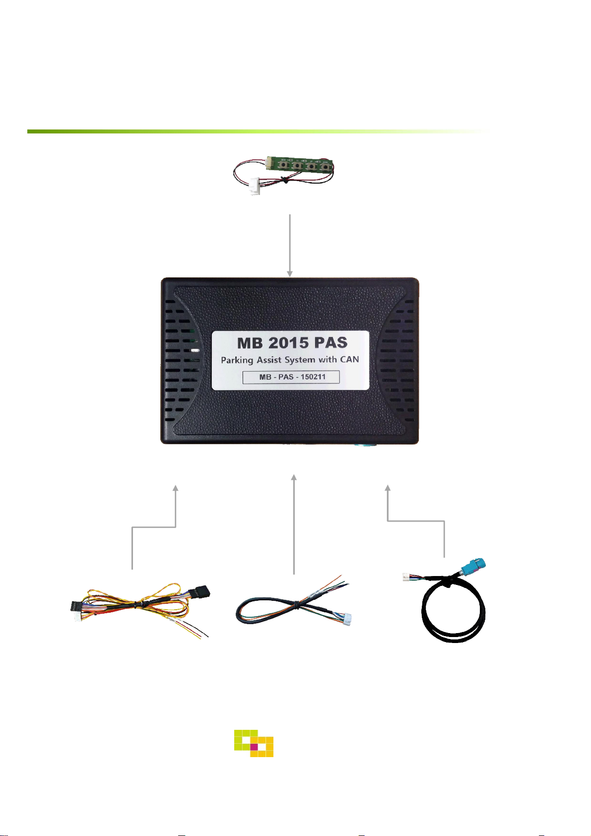
4. Components
OSD Board 1 EA
Power Cable 1 EA LVDS Cable 1 EA
RGB Navi Cable 1 EA
GU Electronic
5
Specification
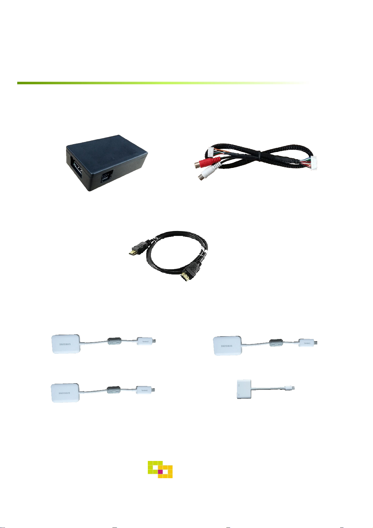
4. Components (Option)
RGB Cable 1 EASub Board 1 EA
Galaxy S2
Galaxy S4
HDMI Cable 1 EA
Galaxy S3
Iphone5/6
MHL Cable
6
GU Electronic
Specification
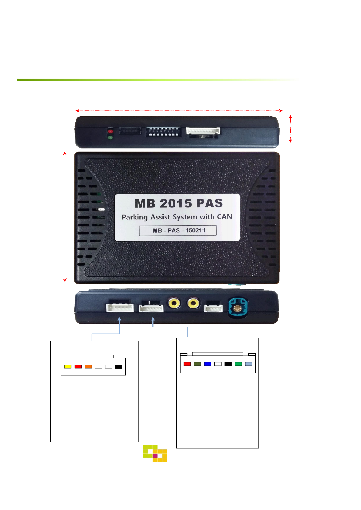
5. Exterior
LED DIP S/W PROGRAMIMAGE
83mm
116mm
21mm
POWER/CAN LCD-OUTLCD-INFRONT REARNAVI
*POWER Connect
① ② ③ ④ ⑤ ⑥
① BATTERY (Yellow)
② REAR_POWER (Red)
③ CAN-HIGH (Orange)
④ CAN-LOW (White)
⑤ NC
⑥ GND (Black)
*NAVI Connect
① ② ③ ④ ⑤ ⑥ ⑦
① R DATA (Red)
② G DATA (Green)
③ B DATA (Blue)
④ SYNC (White)
⑤ GND (Black)
⑥ NC
⑦ +5V
7
GU Electronic

Settings
1. Dip Switch
* ON : DOWN , OFF : UP
NO. Function Selection
1 NAVI (MHL)
2 Video mode
3, 4 N.C
5 Rear Camera Page. 8
6
7 ON : S 12”, 12” Split view
8 ON : S : 12”, 12 Split view, C 8.4”
Car model
ON : Skipping NAVI (MHL)
OFF : Display
ON : Skipping Video
OFF : Display
ON : B,E,CLA,CLS,GLE 7”, 8”
* Example
C class 8.4”Model
C/GLC class 7”Model
Aston martin vantage2018
E/B/CLA/CLS/GLE class
7”/8”Model
GU Electronic
S class 12”Model
S class 12”split view
8

Settings
2. Parking à Drive setting
• Setting time to display screen when changing gear from P to N or D
- The rear screen is displayed for 15sec in N, D gear or until driving up
10km – OEM type
: Dip S/W No.5 “OFF”
After 15sec. in N,D gear
OR
Rear Mode
After driving up 10km
- The rear screen is switched right after changing gear
: Dip S/W No.5 “ON”
Right after changing gear
Rear Mode
Display
Display
GU Electronic
9

Settings
3. Original button
※ The button in Jog shuttle can’t be used in the Car with NTG 5.1
system as this interface has only one pair of CAN wire (the CAN data
of Jog shuttle system in NTG5.1 is different from the steering wheel)
※ MB2015 TAC2 interface is recommended for using the button in Jog
shuttle in NTG 5.1
- Switching mode
Steering wheel Jog shuttle
Steering wheel Jog shuttle
/ NAVI :
1. Long Press: Switching mode
2. Short Press: Switching to OEM directly
GU Electronic
10

Settings
3. Original button
- OSD Setting
①
< S-class >
⑥
③
②
PUSH
⑤
①
① Long press (6sec) :Activating OSD
④
Short press : Exit
( ※ s-class : )
② Select
③ Up, Increasing value
④ Moving from first menu to
third menu in order
⑤ Down, Decreasing value
⑥ Moving from Third menu to First
menu in order
Mode State
First Menu
Second Menu
GU Electronic
Third Menu
11

Settings
4. Key board
①
MENU SEL UP DOWN
②
③ ④
① MENU : Activating OSD Menu
② SEL : Selection
③ Up : Moving upward / increasing value
④ Down : Moving downward / dicreasing value
5. OSD Menu
※Press “MENU” button on Key board
Config - NAVI-RGB(MHL) : Setup for the type of RGB(MHL)
Config - DVB-T(DMB) : Setup for the type of DVB-T(DMB)
Config - DVD : Setup for the type of DVD
Reset : Reset all value
12
GU Electronic

Settings
5. OSD Menu
※Press “MENU” button on Key board
Option
• RearCam- Type : Setup for rear camera
ExtDevice : External rear camera
OEM : Original camera
• RearCam- Power : Setup for Rear VCC wire in power cable
ON : +12V out always (current consumption : 200mA)
AUTO : +12V out in rear mode only (200mA)
OFF : Power OFF
• RearCam- Det : Setup for Rear detection
CAN : By CAN
Extwire : by rear cam detect wire
• FrontCam- Type : Setup for front camera
ExtDevice : External rear camera
OEM : Original camera
• FrontCam- Power : Setup for Front VCC wire in power cable
ON - +12V out always (current consumption : 200mA)
AUTO - +12V out in rear mode only (200mA)
OFF - Power OFF
• FrontCam-Det : Setup for front detection
ExtDevice - External rear camera
OEM - Original carmer
• RearCam-RcvOpt: The time of displaying front camera
OEM
NAVI
AV1(DVB-T)
AV2(DVD)
• AV out : Setup for the external AV out in OEM screen
AV1 : AV1’s Audio comes out in OEM screen
AV2 : AV2’s Audio comes out in OEM screen
USER : select one of Audio out
• Reset – Excute : Option Menu all Reset
REAR FRONT
Select time of display
1~30 second
OEM
NAVI
AV1(DVB-T)
AV2(DVD)
GU Electronic
13
Settings
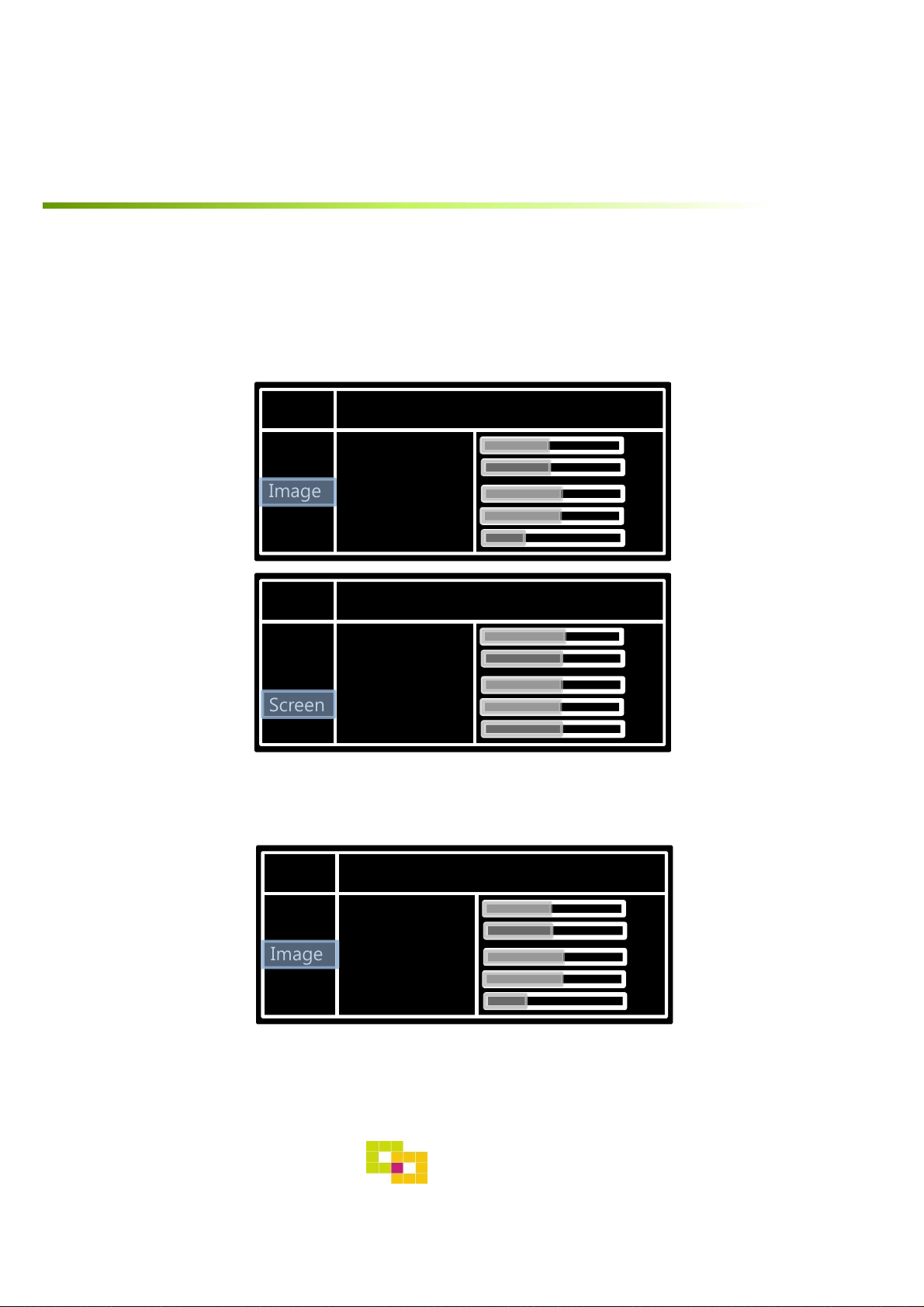
5. OSD Menu
※Press “MENU” button on Key board
- NAVI(RGB) Image / Screen
MENU IMAGE NAVI
Config
Option
Image
Screen
Parking
MENU Screen NAVI
Config
Option
Image
Screen
Parking
Brightness
Contrast
Color- RED
Color- GREEN
Color- BLUE
Horizontal
Vertical
Scale X Up
Scale X Down
Scale X Up
- DVD, DVBT, NAVI-AV, REAR, FRONT Image
MENU IMAGE Rear
50
50
50
50
25
50
50
50
50
50
Config
Option
Image
Screen
Parking
Brightness
Contrast
Saturation
Hue
Sharpness
GU Electronic
50
50
50
50
25
14

Settings
5. OSD Menu – Parking mode
※Press “MENU” button on Key board
-PDC display ON/OFF
Selecting a use of OPS(PDC) picture
(OSD Menu – Parking – OSD Display –
ON or OFF)
- Language
-Parking guide line ON/OFF
Selecting a use of packing guide line
(OSD Menu – Parking – Line display – ON
or OFF)
Selecting a type of language
(OSD Menu – Parking – Warning lang)
15
GU Electronic

Settings
5. OSD Menu – Parking mode
※Press “MENU” button on Key board
-Adjusting the position of guide line
Left Right
Possible to adjust the position of line
by Keypad in Horizontal / Vertical menu
※ Pressing this Horizontal / Vertical menu,
The OSD screen automatically disappears.
Please adjust from the parking line Screen.
MENU SEL UP DOWN
Left Right
Up
Down
Up
: Original mode
: PAS on/off
: Adjustment of brightness
Down
* Can be adjusted by the Jog shuttle
16
GU Electronic
Installation
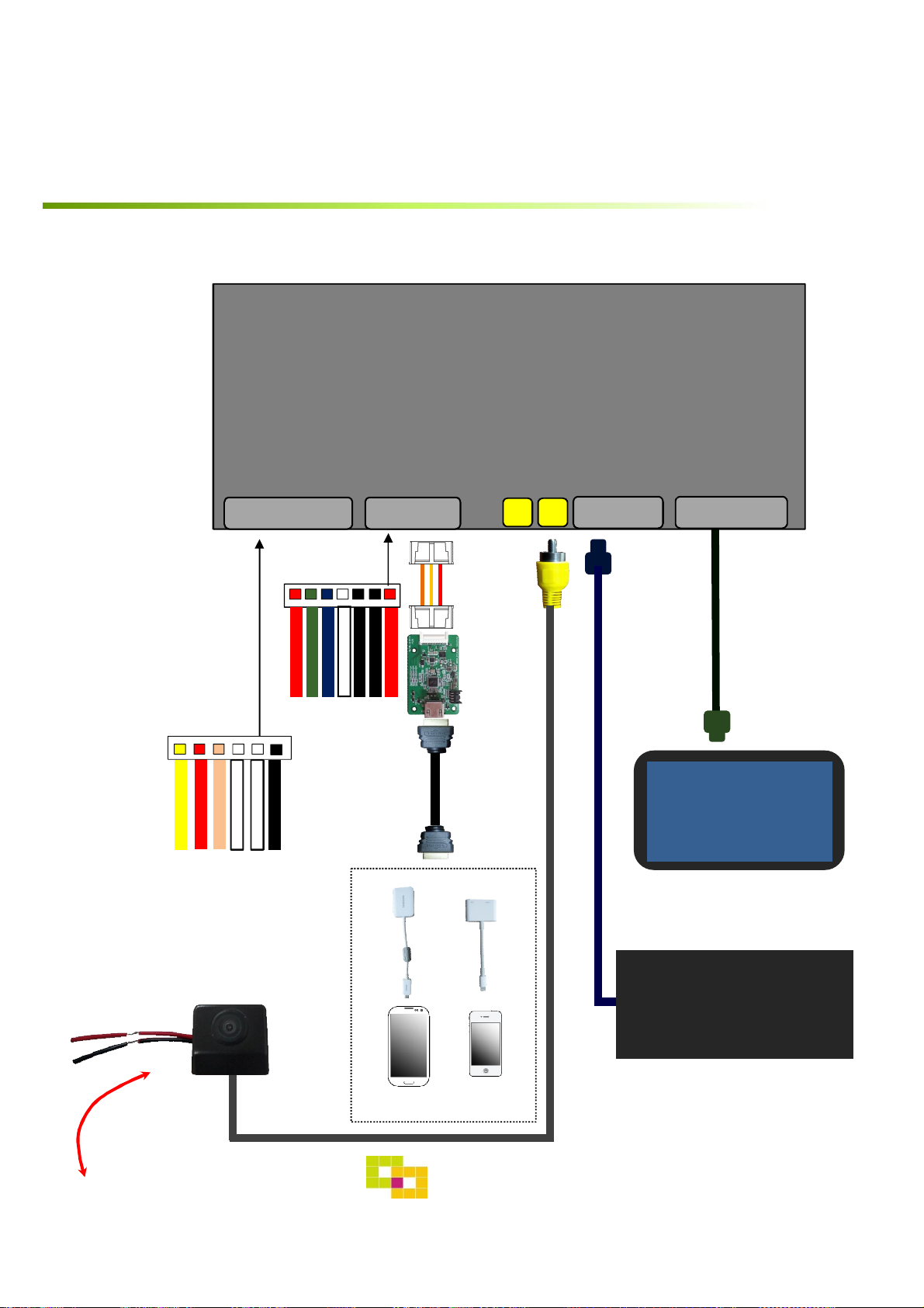
1. Installation Diagram
MB 2015 PAS
INTERFACE
POWER/CAN
BLUE
GREEN
RED
RGB
RGB Cable
Sub Board
+5V
NC
GND
SYNC
HDMI Cable
LCD -IN LCD -OUT
OEM Monitor
GND (Black)
NC
CAN-LOW (White)
CAN HIGH (Orange)
REAR POWER (Red)
BATTERY (Yellow)
MHL Cable
②①
Galaxy
GU Electronic
Command
iPhone
17

Installation
2. LVDS Connection
[Command]
[OEM Monitor]
18
GU Electronic

Installation
3. CAN Connection
① Please remove the indicated
black connector from the OEM
plug&play connector
③ Make sure the direction of an
arrow
② Please push the indicated lock
button to take away connector
GU Electronic
19

Caution
1. FQA
• Not possible to switch mode
- Check connection of OSD Key pad wire
- Check CAN connection
• Display wrong size of picture
- Check Dip s/w setting
• Display black screen in OEM mode
- Check connection of LVDS/LCD cable
• Not possible to switch to rear screen
- Check the packing setting
(OSD Menu – option – RearCam-Det)
2. Caution
• The device must not be installed in where it interferes driving
(close to brake pedal, steering wheel, airbag etc.)
• LVDS cable must be connected correctly according to the manual
• Insulate the end of wire by using electrical tape
• The installation should be done by expert
• GU electronic does not take any responsibility for any problem
caused by wrong installation
-20

GU Electronic
For your better life, better driving
 Loading...