

Page 1
GSS 700P
#94220
© Güde GmbH & Co. KG - Birkichstrasse 6 - D-74549 Wolper t shausen - Deutschland
Deuts ch D 3
Originalbetriebsanleitung
English GB 14
Original Operating Instr uctions
Français F 26
Mode d’emploi or iginal
Čeština CZ 38
Originální návod k obsluze
Slovenčina SK 50
Originálny návod na obsluhu
N ederlands N L 62
Originele gebruiksaanw ijzing
Italiano I 74
Originale del Manuale d’Uso
Magyar H 86
Eredeti hasz nálati utasítás
Slovenščina SLO 98
Originalna navodila za uporabo
Hrvatski HR 110
Originalne upute za korištenje
Bošnjački BIH 122
Originalna uputstva za upotrebu
Rom ână RO 134
Mod de operare - versiune originală
Български BG 146
Оригинално упътване за обслужване
1
Page 2

1 Gerät
Massives Sägeblatt schärfger ät der Oberk l asse. Z um S chärfen von hartm etall bestück te n Sägebl ätte rn von
80 – 700 m m Durchmes ser.
Spezial-Diam antsc hleif scheibe 125 m m , 7 Adapter für all e gängigen B ohrungsdurchm esser .
Professi onell es Sc härfen aller gängi gen Sägeblätter von H andkreis säge n, Tisc hkre iss äge n,
Brennholzsägen, etc.
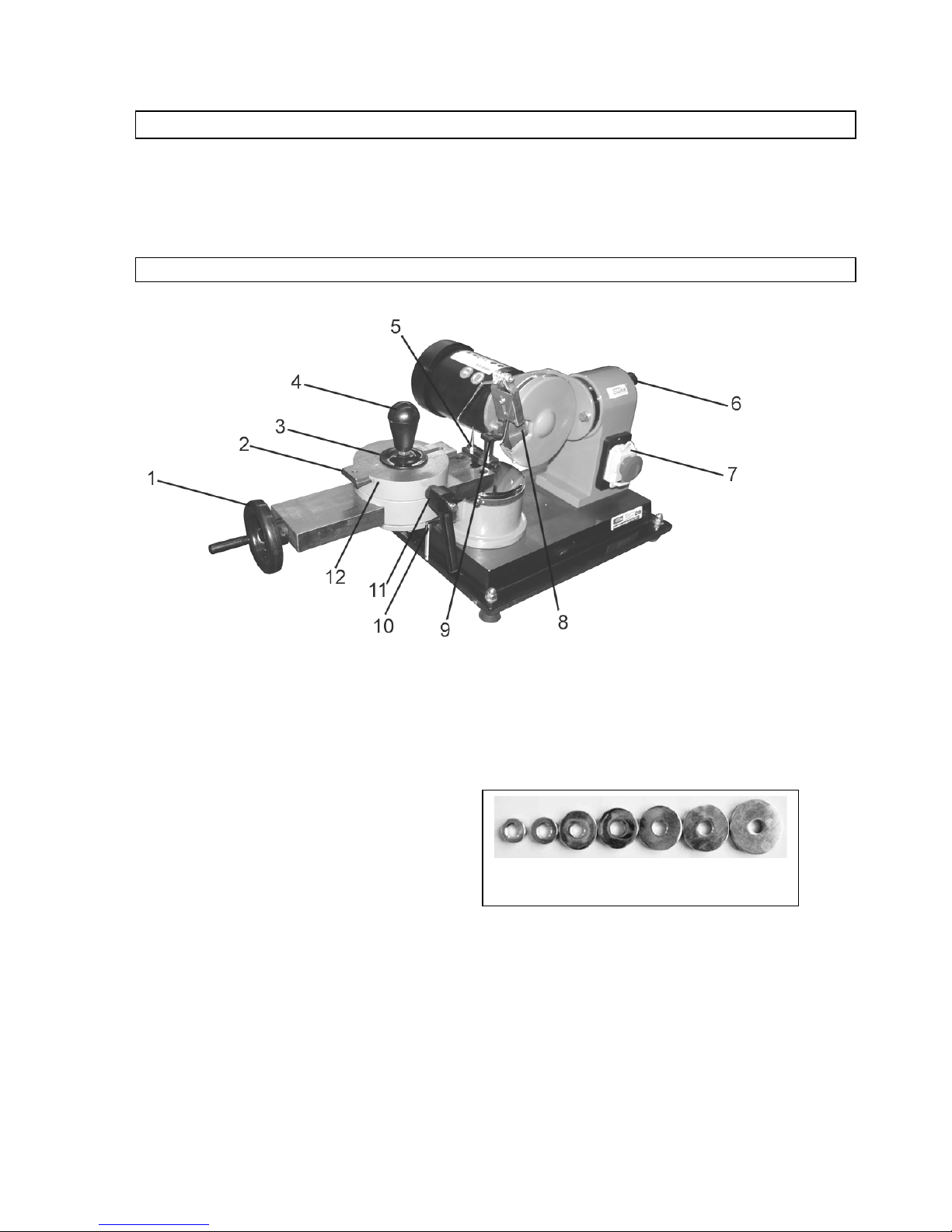
1.1 Lieferumfang
1. Handrad
2. Zustellschlitten
3. Andruckscheibe
4. Klemmschraube
5. Anschlagnadel
6. Klemmhebel Schleifscheibe
7. Not-Aus Schalter
8. Schleifscheibe
9. Auflagebolzen
10. Klemmhebel Auflagentisch
11. Klem m schraube Oberschl itten
12. Klem m schraube Z ustel lschl itten
13. Adapter
13
3
Page 3
1.2 Gewährleistung
Die Gew ährleistungs z eit beträgt 12 M onate bei gewerblicher N utzung, 24 Monate für Verbraucher und
beginnt m it dem Zeitpunk t des K aufs des Gerätes.
Die Gewährleistung erst reckt si ch ausschl ießli ch auf M ängel, di e auf M aterial- oder Herstel lungsfehl er
z urückz uf ühren sind. B ei Geltendmac hung eines M angel s im S inne der Gewährl eistung i st der K aufbeleg der das Verkaufs datum ausz uweisen hat - mi t Verkaufsdatum beizufügen.
Von der Gewährl eistung ausges chlos sen sind uns achgem äße N utzung, w ie z . B. Überlastung des Gerätes ,
Gew altanwendung, Bes chädigungen durch Fre m deinwirkung, Frem dkör per , sowie N ic htbeachtung der
Gebrauchs- und A ufbauanl eitu ng und norm aler V erschl eiß.
2 Allgemeine Sicherheitshinweise
Die Bedienungsanl eitung m uss vor der ersten Anwendung des Gerätes ganz durchgel esen werden. Falls
über den Anschl uss und di e Bedienung des Gerätes Z w ei fel entstehen sollt en, w enden S ie si ch an den
H erstell er (Servi ce-Abteilung).
UM EINEN HOHEN GRAD AN SICHERHEIT ZU GARANTIEREN, BEACHTEN SIE UNBEDINGT
AUFMERKSAM FOLGENDE HINWEISE:
ACHTUNG!
• Das Gerät muss sicher, waagrecht und fest auf einer Werkbank befestigt werden.
• Der Arbeitsplatz muss sauber und ausreichend beleuchtet sein (500 lux).
• Betreiben Sie das Gerät nie in der Nähe von leicht entflammbaren Materialien, Gasen oder Flüssigkeiten.
• T ragen Sie eine Schutzbrille, Gehörschutz und geeignete Schutzkleidung. Falls notwendig zusätzlich
Staubschutzmaske tragen.
• T ragen Sie immer geeignete Kleidung. Tragen Sie keine weite Kleidung oder Schmuck , sie könnten von rotierenden
Teilen erfasst werden. Rutschfestes Schuhwerk wird empfohlen. Bei langen Haaren tragen Sie ein Haarnetz.
• Achten Sie bei der Arbeit mit dem Gerät immer für einen festen Stand.
• Halten Sie andere Personen, vor allem Kinder v om Arbeitsbereich fern.
• Lassen Sie vorhandene Schutzvorrichtungen grundsätzlich an ihrem Platz und stellen Sie deren einwandfreie
Funktion sicher. Der Betrieb ohne Schutzvor richtung ist grundsätzlich untersagt.
• Überprüf en Sie regelmäßig, dass alle Verschraubungen fest montiert sind.
• Vergewissern Sie sich, dass sich das Netzkabel nicht in der Nähe v on rotierenden Teilen befindet.
• Lassen Sie laufende Werkzeuge nicht unbeaufsichtigt. Wenn Sie sich von dem Gerät entfernen schalten Sie es
grundsätzlich aus.
• Entfernen Sie immer den Netzstecker bei Nichtgebrauch, v or Wartung/Reinigung oder beim Werkzeugwechsel.
• Lassen Sie keine Werkzeugschlüssel stecken. Überprüfen Sie v or dem Einschalten, dass die Schlüssel und
Einstellwerkzeuge entfernt sind.
• Bei längeren Werkstücken ist eine zusätzliche Auflagemöglichkeit zu schaffen.
• Halten Sie ihre Hände von den Schleifmitteln fern.
• Ac hten Sie dar a uf, dass die Schleifscheib e nich t har t an das Sägebla tt schlägt! Fü r B es c hädi gungen an der
Diamants cheibe kann keine Haftung übernommen werden.
Gerät darf nu r an einem Str o mn e tz m it FI ( Fehlerstrom schutzs c halte r) bet ri e ben we rden.
4
Page 4
2.1 Verhalten im Notfall
Leiten Si e die der Verletz ung ents prechend notw endi gen Erste Hilfe M aßnahm en ein und fordern S ie
schnell st m ögli ch qualifiz i erte ärz tli che H i lfe an. Bew ahren S ie den Verletz t en vor weiteren S chädi gungen
und stellen S ie diesen ruhig.
Für einen eventu ell ei ntr eten d en Unfall sollte i mm er ein Verb andskasten nach DIN 13164 am
A rbeitsplatz griff bereit vorhan den sein. Dem V erban dsk ast en entno m menes Mat er ial ist sofort
wieder aufzufü llen.
Wenn Sie Hilfe anfordern,
ma chen Sie folg end e A nga ben :
1. Ort des Unfalls
2. A rt des Unfalls
3. Zahl der Verletzten
4. A rt der Verl etz u ng e n
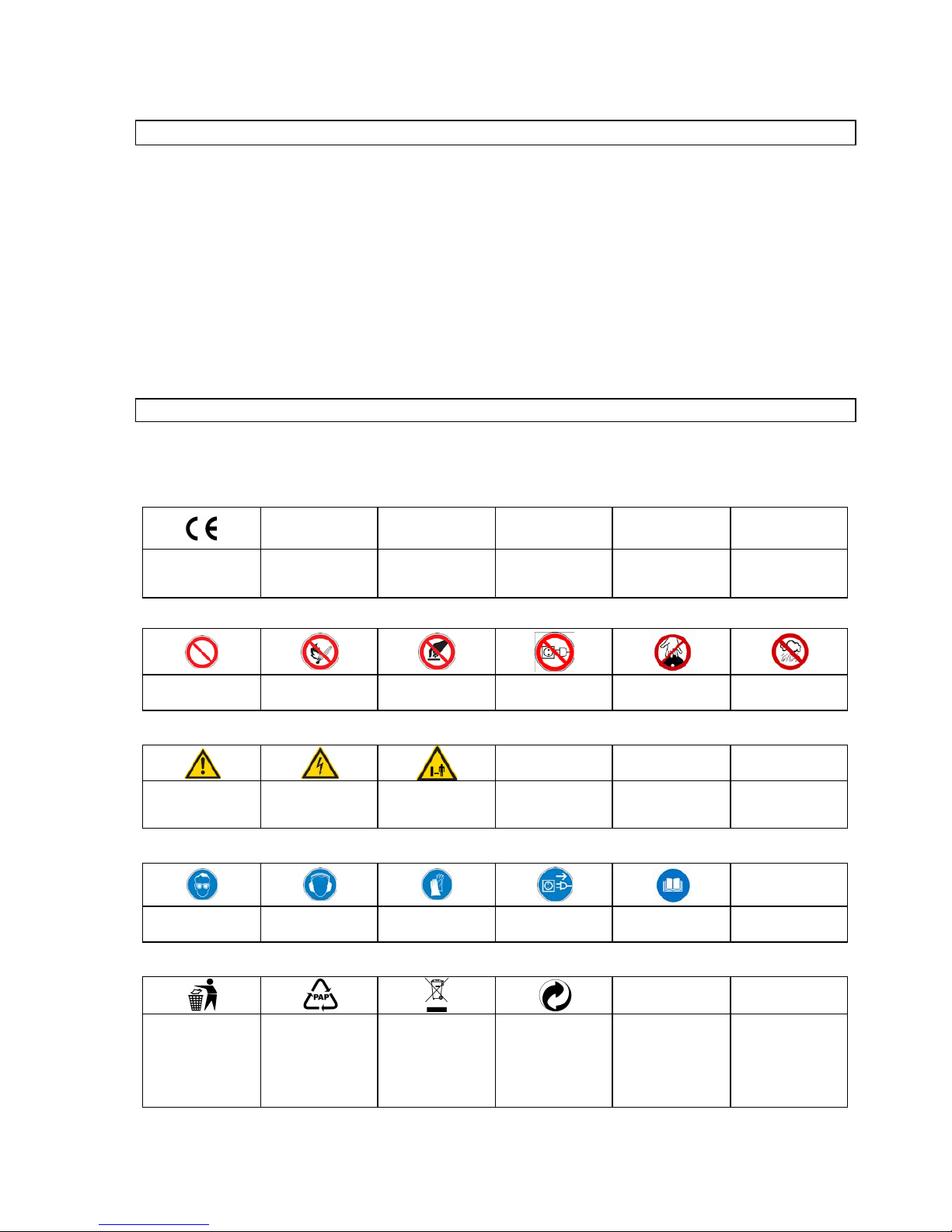
2.2 Kennzeichnungen auf dem Gerät
Erkl ärung der S y m bol e
I n dieser Anleitung und/ oder auf dem G erät w erden folgende S ym bole v erw endet:
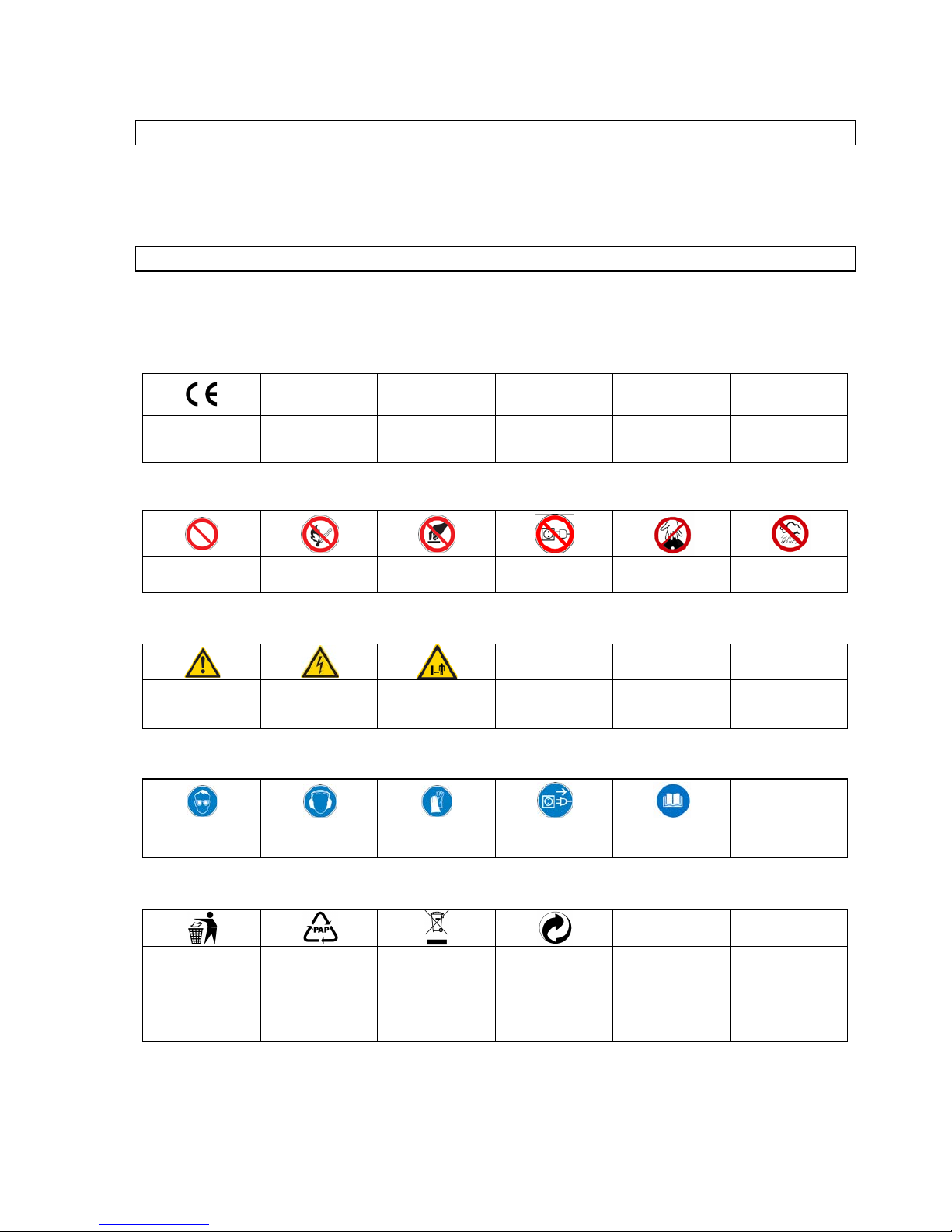
Produktsicherheit:
Produkt ist mit den
einschlägigen Normen
der Europäischen
Gemeinschaf t konform
Verbote:
Verbot, al lgemein
(in Verbi ndung m it
anderem Piktogramm)
Feuer, offenes Li cht
und Rauc he n ver bote n
Berühren verboten
Am Kabel ziehen
verboten
Nicht in rotierende
Teil e fassen
Gerät nicht bei Nässe
verwenden
Warnung:
Warnung/Achtung
Warnung vor
gefährlicher
elek tr is c her Span nung
Sicherheitsabstand
einhalten
Gebote:
Augens c hut z ben utze n
Gehör s c hutz ben u t zen
Schutzhandschuhe
benutzen
V
or Ö ffnen N etz stecker
ziehen
Vor Gebrauch
Bedienungsanleitung
lesen
Umweltschutz:
Abfall nicht in die
Umwelt sondern
fachger ec h t en t sorge n.
Verpackungsmaterial
aus Pappe kann an
den dafür vorgesehen
Recycling-Stellen
abgegeben werden.
Schadhafte und/oder
zu entsorgende
elektrische oder
elektronische Geräte
müssen an den dafür
vor gesehen Recy c li n g
-
Stellen abgegeben
werden.
Der Grüne Punkt –
Duales System
Deutschland AG
5
Page 5
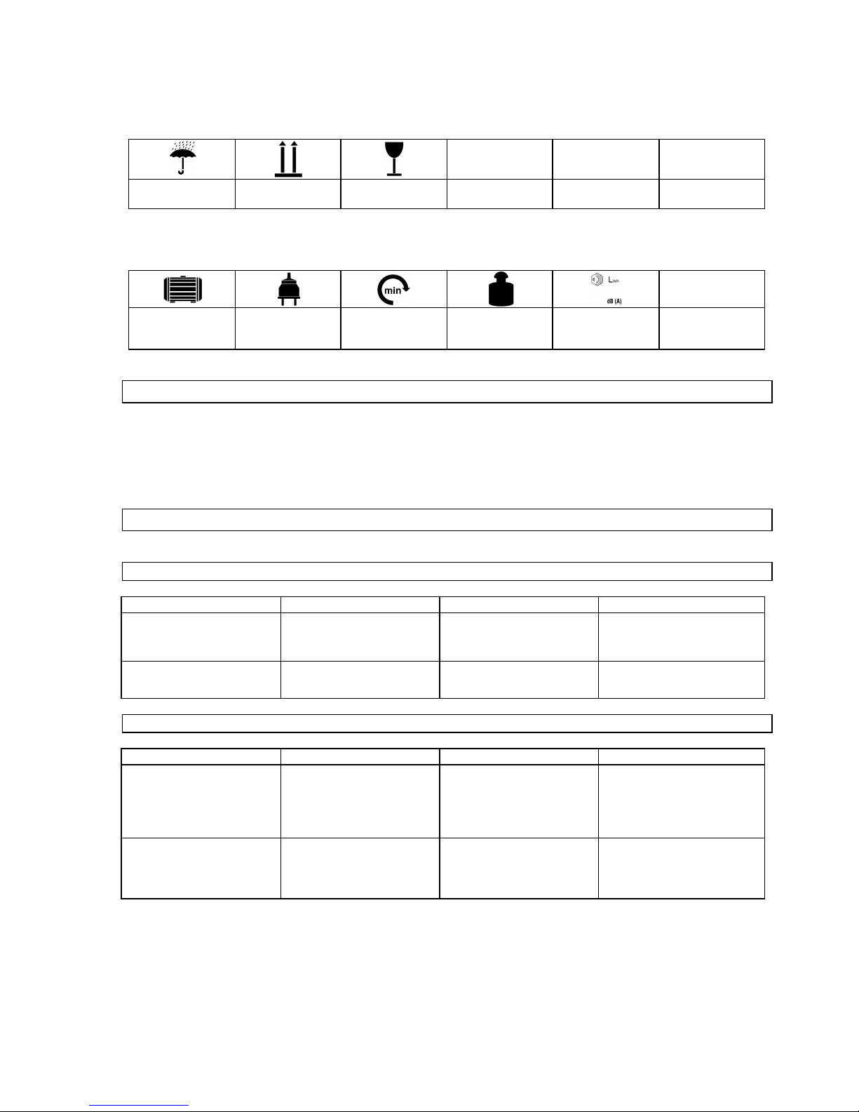
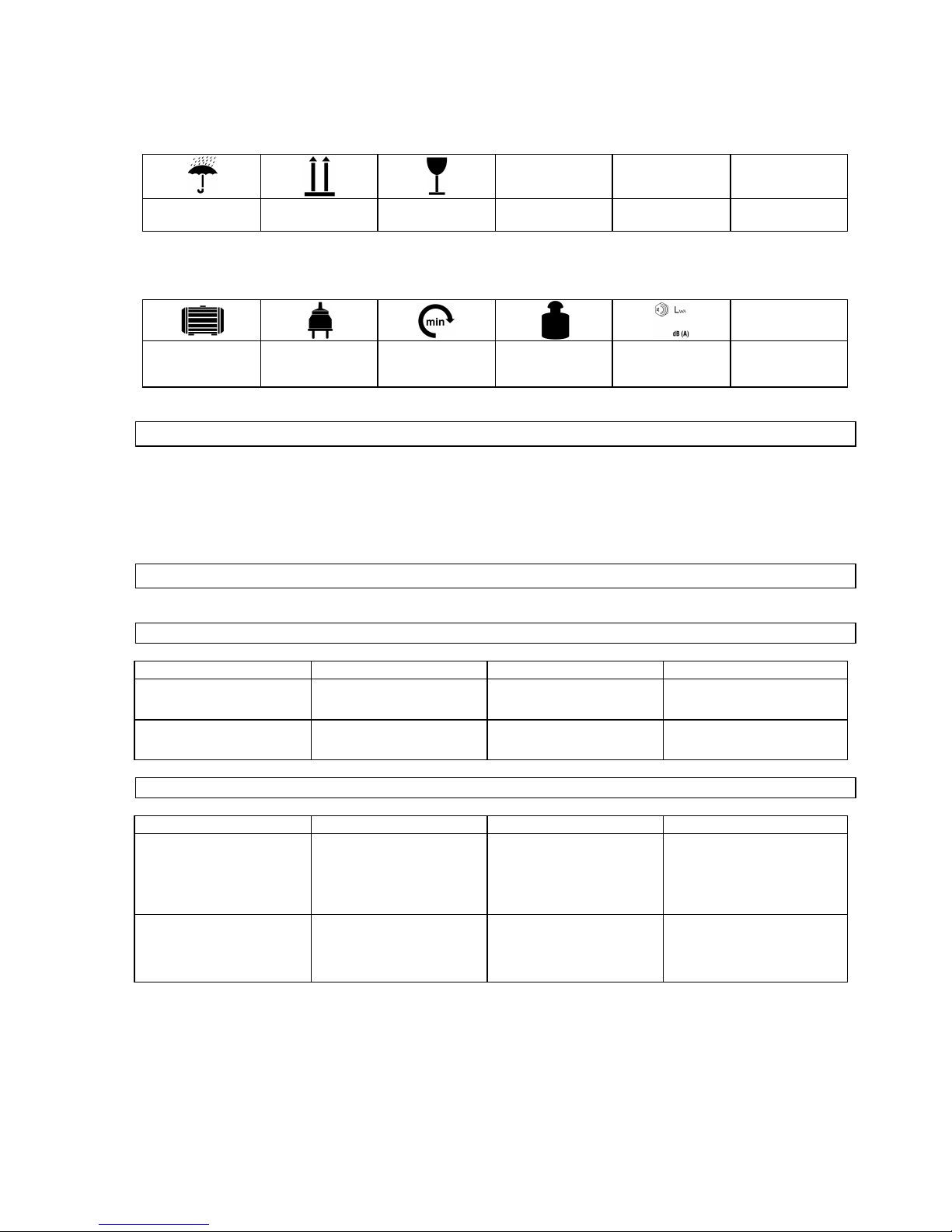
Verpackung:
Vor Nässe schützen
Packungsorientierung
Oben
Vorsicht zerbrechlich
Technische Daten:
Motorleistung Netzanschluss
Umdrehungen in der
Minute
Gewicht Schallleistungspegel
2.3 Bestimmungsgemäße Verwendung
Das Gerät darf ausschließli ch z um S chl eifen/S chärfen und Bearbei ten von H artm et allbest ückten
Sägeblätt ern verw endet werden.
Bei N ichtbeac htung der Best im m ungen, aus den al lgem ein gül tigen V orschriften s ow i e den Besti m m ungen
aus dieser A nleit ung, kann der H erstel ler für S chäden nicht v erantw ortli ch gem acht werden.
2.4 Restgefahren und Schutzmaßnahmen
2.4.1 Mec hanische R estgefahren
Gefährdung
Beschreibung
Schutzmaßnahme(n)
Restgefahr
Erfassen, Aufw ickeln
Weite Kleidung oder Schmuck
kann von den bew eglichen
Teil en erfasst w erden.
Tragen Sie stets eng
anliegende Kleidung und
keinen Schmuc k der er fass t
werden kann.
Reibung, Abrieb
Berühren der rotierenden
Schleifmittel kann zu schweren
Ver letzungen f ühr en.
Verm eiden Sie stets den
Kontakt mit dem Schleif mittel.
Tragen Sie Schutzhands chuhe.
2.4.2 Elektrische Restgefahren
Gefährdung
Beschreibung
Schutzmaßnahme(n)
Restgefahr
Dir ekter elektrisc her Kontakt
Ein def ektes Kabel oder
Stecker kann zum Stromsc hlag
führen.
Lass en Sie def ekte Kabel oder
Stecker immer vom Fachmann
austauschen. Verw enden Sie
das Gerät nur an einem
Anschluss mit Fehl erstrom-
schutzschalter (FI ).
Indir ekter elektrisc her Kontakt
Ver letzungen dur ch
spannungsführende Teile bei
geöffneten elektrischen oder
def ekten Bauteilen.
Immer bei Wartungsarbeiten
den N etzstecker ziehen.
Verwenden Sie das Gerät nur
an einem Anschluss mi t
Fehlerstromschutz s chalter (FI).
6
Page 6

2.4.3 Gefährdungen durch Lärm
Gefährdung
Beschreibung
Schutzmaßnahme(n)
Restgefahr
Gehörschädigungen
Längeres Arbeiten mit dem
Gerät kann zu
Gehörsc hädigungen f ühren.
Tragen Sie stets einen
Gehörschutz.
2.4.4 Gefährdung durch Werkstof f e und andere St offe
Gefährdung
Beschreibung
Schutzmaßnahme(n)
Restgefahr
Kontakt, Einatmung
Bei großer Staubentw icklung
kann dieser z u Schädigungen
der Lunge führen.
Beim A rbeiten mit dem Ger ät
muss immer eine
Staubsc hutzmas ke getragen
werden.
2.4.5 Vernachläs sigung ergono m i scher Grundsä tze
Gefährdung
Beschreibung
Schutzmaßnahme(n)
Restgefahr
Nachlässiger Gebrauc h
pers önlicher Schut zaus rüs tung
Bedienung des Gerätes ohne
die entsprec hende
Schutzausrüstung kann zu
schweren äußeren sow ie
inneren Ver letzungen f ühr en.
Tragen Sie stets die
vorgeschriebene
Schutz kleidung und arbeiten
Sie bedacht.
Unangemessene örtliche
Beleuchtung
Mangelhafte Beleuchtung s tellt
ein hohes Sicherheitsrisiko dar.
Sorgen Sie bei der A r beit mit
dem Gerät immer für
ausr eichende Beleuchtung.
2.4.6 Sonsti ge Gefährdungen
Gefährdung
Beschreibung
Schutzmaßnahme(n)
Restgefahr
Herausgew orfene Gegenstände
oder Flüssigkeiten
Beim Schleif en können
Schleifmittel- oder
Mediums partikel Ihr e A ugen
verletzen.
Tragen Sie bei der Arbeit mit
dem Gerät immer eine
Schutzbrille.
2.4.7 Entsorgung
Die Entsorgungshinweise ergeben si ch aus den P iktogram m en di e auf dem Gerät bz w. der Verpack ung
aufgebracht sind. E ine B eschrei bung der einz el nen Bedeutung en f inden S ie im Kapitel „Kennzeichnungen
auf dem Gerät“.
2.5 Anforderungen an den Bediener
Der Bedi ener mus s vor Gebrauch des Gerätes aufm erksam die B edienungs anle itung gel ese n haben.
2.5.1 Qualifikation
Außer einer ausführli chen E inw ei sung durch eine s achkundi ge Person i st kei ne spez iel le Quali fik ation für
den Gebrauch des Gerätes notwendig.
2.5.2 Mindestalter
Das Gerät darf nur von Personen betrieben werden, die das 16. Lebensj ahr vollendet haben.
Eine Ausnahm e stel lt di e Benutz ung als Jugendl icher dar, wenn die Benutzung im Zuge einer
Berufsausbi ldung z ur E rreichung der Fertigke i t unter Aufs icht ei nes A usbil ders erfolg t.
2.5.3 Schulung
Die Benutz ung des Gerätes bedarf ledigl ich ei ner entsprech ende n Unterw eisung. E ine s pez iel le S chulung i st
nicht notwendig.
7
Page 7
3 Technische Daten
GSS 700 P
Anschluss:
230V/50 Hz
Frequenz / S chutza r t:
IP 4 4
Schutzklasse:
I
Max. Leistung P1:
370 W/P 1/S6/40%
Motordrehzahl:
280 min-1
Schleifscheib e Ø ca.:
125 x 32 mm
Einstellwinkel Schleif scheib e:
2 x 30°
Einstellwinkel A uflagentisch:
30° links/80° rechts
Adapter für Sägeblatt au fna hme:
35 mm, 30 mm, 28 mm, 25,4 mm, 25 mm, 18 mm, 16 mm
Anschlusskabel:
1,5 m/H 05 VV-F
Gewicht ca.:
38 kg
Schallleistungspegel
73 dB (A )
Maße L x B x H in mm:
670 x 390 x 310
Artike l-Nr.:
94220
4 Transport und Lagerung
Das Gerät ist nur für de n station är en E i nsa tz konzipi ert.
U nbenutz te Werkz euge sol lten i n einem trockenen, v erschlos senen Raum aufbewahrt w erden.
5 Montage und Erstinbetriebnahme
Das Gerät wi rd fertig m onti ert geliefert, S ie m üs sen es lediglic h der Verpackung entnehmen.
• Reiben Sie die blanken Teile des Sc hiebeschl ittens regelm äßig m it ei nem öligen Lappen ei n und
schm ieren S ie die Spindel vor jedem Ei nsatz.
5.1 Sicherheitshinweise für Erstinbetriebnahme
• Achten Sie auf eine sic here Befesti gung des Gerätes auf einer geeigneten Oberfläc h e.
• Stellen S ie sicher, dass all e Verschraubungen fest si nd.
5.2 Vorgehensweise
• Führen Sie di e M ontage der Ei nz eltei le in der dargestellt en Reihenfol ge durch. A chten S ie dabei auf
die richti ge Anordnung der B auteile gem äß den A bbildungen.
8
Page 8

6 Bedienung
Abb. 1
Grundsätzli ch könn en S ägeblatt du rchm ess er von
80 mm bis 700 mm geschärft werden .
Das Sägeblatt wird hierzu auf dem Z ustells chl itt en
montiert. Der Zustellschlitten besitz drei Zentrierbohrunge n , je nac h W ahl der Z entri er b ohrung,
können untersc hi edlic he Sägeb lat td urchm es ser
mont iert wer den .
Abb. 2
Wähl en Sie zuer st di e pas s en de Z entr i er bo hr un g,
hierzu öff nen S ie die K lem m s chr au be A bb. 1b, de r
Zustellschlitt en kann nun um 360° verdreh t
werden. Bei kleinen D urchm es sern des
Sägeblattes emp fieh lt sich die Z entri erb ohru n g
A bb. 2a, bei mittleren Durch messer n ein e der
anderen zwei Bohr ungen . Mit Hilfe des Hand ra des
kann auch der Ober sch litt en ein gestellt werden,
hierzu ist zuerst die Klem mschr au be A bb. 1c, zu
lösen. Nach Lösen der K lemmsch ra ube kann der
Durchmesser für das zu schärf ende S ägebla tt
voreingest ellt werden.
Abb. 3
Ist der passende A bstand zwisch en
Zentrierbohrung und Schleifscheibe gefunden,
wird der Oberschlitt en m it der Klemm schr aub e
A bb. 1c fixiert, jetzt kann das Blatt m ittig über der
Z entrierboh ru ng aufg elegt wer de n . L ege n S ie nun
den passen den Adapter i n die Boh ru ng des
Sägeblattes.
Über dem A da pter wi rd nun die Andruc ks ch ei b e
A bb. 3a gelegt und mit der Klemm schrau b e
befestigt.
TIPP: Ziehen Sie die Klem mschr au be nur so fest
an, dass sich das Sägeblatt noch ohn e großen
Kraftaufwand verdr ehen lässt .
c
a b a
a
9
Page 9
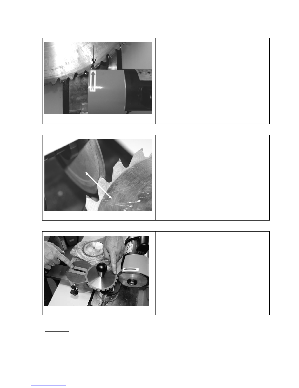
Abb. 4
Erm i tteln Si e zunä chs t de n S chnei d ewi n kel , um
die Zahninnenflä ch en zu schärf en, dies e m üssen
exakt parallel z ur geraden Flä ch e der Schleifscheibe stehen . (sieh e Pfeil Abb.4 und Abb. 5)
Abb. 5
Das Sc härfen erfol g t dur ch vor und z urü ckschieben des Z ustells chl ittens , w obei darauf z u
achten ist, dass der Zustel lsch litt en so eingestel lt
ist, dass nur die Hartmetall bes tüc ku ng geschärft
wird und das L angloc h im S chl itten a ls
Endanschlag dient. (siehe Abb. 6)
Abb. 6
Hier ist deutli ch z u sehen , dass der
Zustellschlitt en parall el zur Schleif schei be
eingestellt ist und der Schlitten auf A nschlag
fährt, die Schleifsc heib e schl eift nur die
Hartmetallbest ück ung. A uch deutl ich z u sehen ist
die Einstellun g für ein klein eres S ägebla tt.
Achtung: Bewegen Sie das Sägeblat t auf dem Schlitt en äußerst vorsi chtig um Schäden an der
Diam antscheibe zu vermeiden !
a
10
Page 10
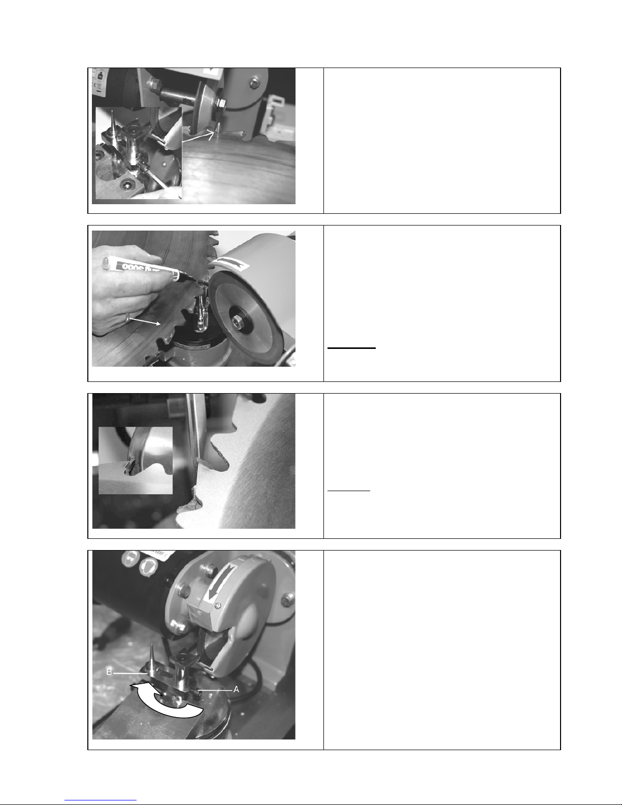
Abb. 7
Um nicht in das Sä geblatt z u schleifen , m uss die
A nschlagnadel montiert werden. Di es e wird mit
dem Im busschlüssel am A uflagenbolzen justier t
und arretier t .
Abb. 8
Mit einem Mark ier stif t werden die Sägezäh ne
markiert, so kann m an den Materia labtra g gut
erkennen und kontrollieren.
Wenn der W inkel der S chleifs ch eib e so einges tell t
ist, dass die Zahinnenflä ch e gleich m äß ig
geschliffen wird, kan n das Sägeblat t Z ahn für
Zahn geschärft wer den.
Achtung: Fahren Sie mit dem Sägeblatt immer
ganz zurück und vermei den S ie ruckartige
Bewegungen , die die Schleifs ch eib e besch äd ig en
könnten.
Abb. 9
Um die Dachschneid en zu schärfen wird die
schräge Vorderseite der S chleif sch eib e genutzt ,
die Winkel sind wie bei den Zahninn enf läch en zu
ermitteln und ents prech en einzus tell en.
Arbe iten S ie auch hi er m it Anschla gd or n um den
gleichmäß igen Enddurc hmesser des Sägebla tt es
einhalt en z u könn en .
Achtung:
Um den Werkzeug sch lit ten in die
korrekte Positi on zum schärf en der Dachsch eid en
schwenk en z u könn en , ist es notw en di g, die
A nschlagnadel auf die Moto rs eit e zu drehen.
(Abb.9A)
Abb. 9A
Dazu muss die Imbusschraube (Abb.9A-A) gelö st
und die A nschl agn ad e l auf di e Mot or seite ge d r eht
werden!
a
11
Page 11
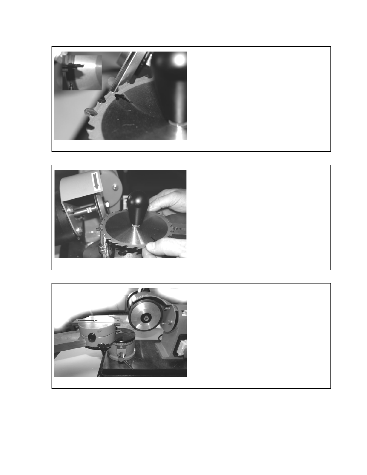
Abb. 10
Bei Wechselverza hn un g muss die Schleif sch eib e
der Neigung des Wechs elzah n es ang epasst
werden (jeder zwei te Zahn wird gesch liff en ).
Abb. 11
Nun wi rd der vorei n ges te llte Wi nk el in
entgegengesetzter Richt un g eingest ellt . Jetzt
können die übri gen Z ä hne ges c här ft werd en.
Tipp: Mit Markierst ift arb eit en .
Abb. 12
Sollten Sie kleine S ägeblätt er sch ärfen , kann es
ratsam sein, den A uflagenb olz en heraus zud r eh en.
Dies sollten Sie je nach S ägeblatt und
Scheidengeo m etri e indi viduell erm it teln .
12
Page 12
6.1 Sicherheitshinweise für die Bedienung
Z iehen S ie vor allen Wartungs-/Einstell- und Reini gung sarb eiten den Netz stec ker. Ebenf alls ist nach
Arbeits ende der N etz s tecker z u z iehen.
• Benutz en Sie das Gerät erst nachdem S ie die Bedienungsanl eitung aufm erk sam gelesen haben.
• Beachten Sie al le in der Anlei tung aufgeführten S icherhei tshin weise.
• Verhalten Sie s ich verantw ortungsvol l gegenüb er ander en Pers one n.
6.2 Schritt-für-Schritt-Anleitung
• Drehen Sie den Sc hiebeschl itten m i t den Aufnahmebohrung je nac h Sägebl attdur chm ess er in die
notw endige P osi tion.
• Wählen Sie den passenden Aufnahm eadapter und fix ieren S ie das B latt.
• Stellen S ie den Schlitt en so ein, dass bei Anschlag am Langloch nicht v ersehentli ch in das B latt
geschli ffen w erden kann.
• Schw ärz en Sie die Zahni nnenflächen m i t einem S tift ein und legen Si e die Schl eifschei be im
Ruhez ustand s auber an die zu schleifende Fläche an.
• Schalten Si e nun das Schärfgerät ein und kratzen Sie di e eingeschw ärz te Fläche zur Endjus tage an.
• Schleifen S ie nun je nach Sägebl attdurchm ess er Zahn für Z ahn sehr vorsi chti g.
• Wenn alle Zahninnenflächen ges chli ffen si nd, schl eifen S ie die Z ahndächer an der sc hräg Fläche der
Schei be m ittel s Anschlag glei chm äßig an, um den Rundlauf das B lattes z u gewährl eisten.
• Maschine ans chließend gründli ch reini gen !
7 Störungen - Ursachen - Behebung
A CHTUNG: IMMER ZUERS T DIE ÜBERLA ST UNGSSICHERUNGEN ÜBERPRÜFEN !
Störung
Ursache
Behebung
Schei be brennt
(stumpf)
1. Schärffl äche z ugesc hm iert.
2. Diam antbesc hichtung v erschli ssen.
1. Mi t Schärfstick reinigen.
2. Blatt wechseln.
7.1.1 I nspekti on und Wartung
Z iehen S ie vor allen Wartungs-/Einstell- und Reinigungsarbei ten den Netz stecker. E benfal ls is t nach
Arbeits ende der N etz s tecker z u z iehen.
Halten Sie das Gerät stets sauber und Staubf rei.
Öl en Si e den Schiebeschl itten gut ei n um ruckartige Bew egungen zu vermei den.
13
Page 13
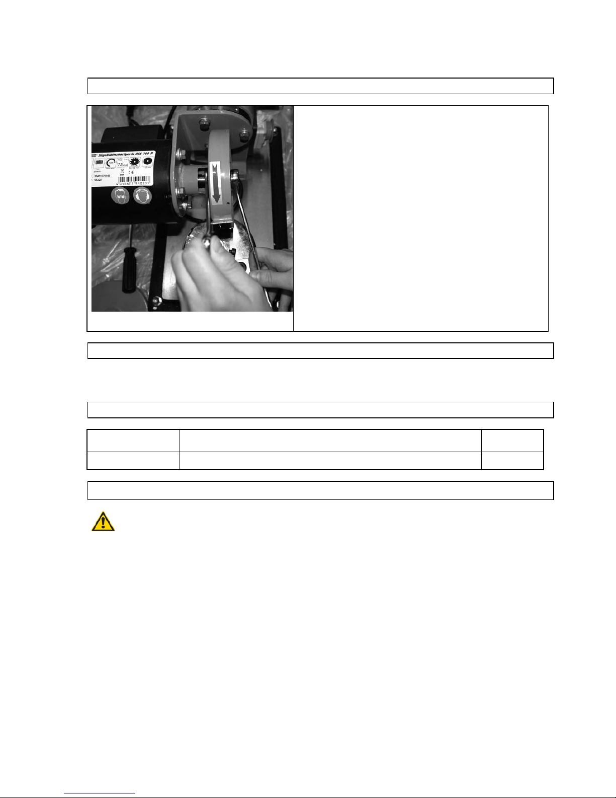
7.2 Wechsel der Schleifscheibe
Abb. 13
Zum Wechsel der Schleif sch eib e wird der Zweikant au f
der Motor wel le mit einem Gabel-schlü ss el arreti ert ,
nun kann die Si cher u ng s -mut ter auf der Moto rw ell e in
Drehrichtu ng des Mot ors gelös t oder fest gezog en
werden (norm ales Recht sg ewin de) .
7.3 Sicherheitshinweise für die Inspektion und Wartung
N ur ein regelmäßig gewartetes und gut gepfl egtes Gerät kann ei n z ufriedenst e llendes H il fsm ittel sein.
Wartungs- und Pflegemängel können z u unv orhersehba ren U nfäl len und V erletz ungen führen.
7.4 Inspektions- und Wartungsplan
Zeitintervall
Beschreibung
Evtl. weiter e
Details
Nach jeder Benutzung
• Reiben Sie das Ger ät mit einem sauber en, trockenen Tuch ab oder blas en Sie es
mit Druckluf t bei niedrigem Druck ab.
8 Ersatzteile
Reklam ati onen und Ersat z teil bestell ungen w erden schnel l und unbürokra ti sch m i t einem
entsprechenden Serv ice-For mul ar unter
http://www.guede.com/support
abgewickelt.
Dieses Formul ar kann auch unter
Tel.: +49 (0) 79 04 / 700-0
Fax: +49 (0) 79 04 / 700-250
E-Mail: info@guede.com
angefordert werden.
14
Page 14
1 Unit
Prem ium solid grinding mac hine for saw discs . To sharpen saw discs of hard metal of diameter
80 – 700 m m .
A special diam ond gri nding w heel of 125 mm , 7 adapters to w ork any usual bores.
Professi onal sharpeni ng of any com m on saw discs of manually operated circular saws, fire wood saw s,
bench circul ar saw s etc.
1.1 Scope of Delivery
1. Hand wheel
2. Feed slide
3. Clamping disc
4. Bindi ng screw
5. stop needle
6. Grinding dis c cl ampi ng lever
7. Em ergency s w itc h
8. Grinding dii sc
9. support screw
10. Support bench clam pi ng lever
11. Upper slide clamping screw
12. Feed slide clam ping s crew
13. Adaptors
13
16
Page 15
1.2 Warranty
A warranty peri od of 12 m onths applies to com m erci al use and 24 months apply to pri vate use and
com m ences on the day of purchase of the devi ce.
Warranty appli es ex cl usiv ely to fai lures due to defective m ateri al or w orkm ans hip. A n original sale sl ip w i th
indicati on of date of sal e must be presented in case of cl aim ing for the w arranty rights.
Warranty does not c over unprofessional use such as dev ice ov erload, viol ent use, dam age caus ed by third
party or foreign m aterials , fail ure to com ply with operations and assem bly m anual, and norm al wear and tear.
2 General Safety Instructions
Prior to the initial use of the unit, the operating ins tructions should be read com pl etely. If in doubt w i th regard
to connection and operati on of the unit, consult the m anufacturer (servic in g depar tm ent).
F OLLOW THE INSTR UCTIONS BELOW CAREFULLY IN ORDER TO SECURE A HIGH DEG REE OF
SAFETY:
Caution!
• T he unit should be safely attached to the bench horizontally.
• Your work place should be kept clean and sufficiently lit (500 lux).
• Never use the unit close to flammable materials, gases and liquids.
• Wear protection goggles, ear protectors and suitable protection clothing. Use a respirator if necessary.
• Wear clothes fitted to the occasion. Do not wear loose clothing or jewels that could be caught by rotating parts. Non-
skid shoes are recommended. If your hair is long, wear a hairnet.
• Mind a stable poise and good footing when working with the unit.
• Other persons, children in particular, should be kept away from the work site.
• Always leav e the existing protection equipment in place and make sure that they work perfectly. The operation
without the protection equipment is not allowed.
• Make regular checks to see that all the screwed joint are fitted firmly.
• Make sure that the power supply cable is not taken within the reach of rotating parts.
• Do not leave the unit unattended if it is running. Any time you leave the unit, switch it off. Do no leave any
adjustment wrenches stuck in the unit. Before switching on, make sure that all the wrenches and adjusting tools are
removed.
• Any longer products should be supported.
• Av oid any contact with grinding aids and materials.
•
• Be careful to avoid a ny hi t on t he s aw disc. No warran t y may be gra n t e d aga in st the diamon d disc damag e .
The unit is allow ed for use in FI mains (stray current protection)
17
Page 16

2.1 Emergency Action
Apply the first aid adequate to the inj ury and get quali fied m edic al assi stance as quickl y as possible. P rotect
the injured person from m ore acci dents and cal m him/her dow n.
2.2 Signs on Unit
Meani ng of S y m bol s
Symbols shown below ar e used throughout this manual and/or on the unit:
Product Sa fety
Product compli ance
with respecti ve EU
standards
Bans:
General ban
In combination with
another pictogram)
No fire, no open light
and no smoking
No touchi ng No pulling the cable
Do not touch rotating
parts
Do not use the unit in
rain
Warning:
Warning/caution
Beware of hazardous
electrical voltage
Keep at safe distance
Commands:
Use goggles Use ear protectors Use protective gloves
Unplug be fo r e openin g
Read oper ati n g man ual
before use
Environm en t P rot ec ti on
Wastes to be disposed
of in a professional
manner no t t o ha r m t he
environment.
Cardboard packaging
to be collected for
recycling.
Faulty and/o r dis posed
of electr ica l/elect r onic
appliances to be
collecte d by auth oris ed
salvage places.
Green Dot –Duales
System Deutschland
AG
18
Page 17
Packaging
Protect from moisture
Keep Up Fragile
Technical Data:
Motor capacity Connection Speed Weight Acoustic output level
2.3 Assigned Use
The unit should be used exclusi vely to grind/sharpen and work hard metal saw discs .
The m anufact urer shall not be m ade l iable for dam ages if general rules and this m anual regulations are not
observed.
2.4 Residual Hazards and Protective Action
2.4.1 Mec hanical Resi dual H azards
Hazard
Description
Protective action
R esidual hazards
Catching, w inding
Loose-fitting clothes, jew els or
long hair may be caught by
moving parts .
Wear tight-f itting garments and
no jewels. Protect your hair w ith
a hairnet.
Friction, abras ion
A contact w ith the rotating
grinding w heel m ay result in
serious injuries.
Alw ays prevent any contact of
your hands w ith the wheel.
Wear protective gloves.
2.4.2 Elec trical Residual H azards
Hazard
Description
Protective action
R esidual hazards
Dir ec t electr ical contac t
Defective cable or plug m ay
cause an electrical shock
Have the defective
cable/plug exchanged by
a professional . Use t he
unit only if connected v ia
a faulty c urrent sw i tch
(FI).
Indirect electrical contact
Wounds caused by conductive
parts on open electrical or
defective structural parts
Alw ays unplug before any
maintenance.
Operate only w ith FI sw itch
installed.
19
Page 18

2.4.3 Noise Hazards
Hazard
Description
Protective action
R esidual hazard
Impaired Hearing
P rolonged work with the saw
may r esult in hearing
impairment
Alw ays wear ear protectors
2.4.4 Materi als and Ot her Substanc es H azards
Hazard
Description
Protective Action
Residual Hazards
Contact, aspiration
Lungs may be affected by great
amount of dust being f or med
Alw ays wear breathing mask
when w orking with the unit.
2.4.5 H um an Factors N eglect
Hazard
Description
Protective Action
Residual Hazards
Negligent use of personal
protec tion equipment
Operating the unit w ithout
adequate PPE may caus e
severe external/internal injuries
Alw ays wear prescribed
protective clothing and work
considerately.
Inadequate local lighting
Insufficient light is a heavy
safet y ri sk .
P rovide for sufficient lighting
2.4.5 Other H az ards
Hazard
Description
Protective Action
Residual Hazards
Thrown aw ay articles and
splashes
The band or mechanical
particles may w ound your eyes
in the course of grinding job.
Alw ays wear protection
goggles.
2.4.6 Disposal
Dispos al ins tructions are gi ven by pic tographs on the unit or packaging. For m eaning of i ndivi dual sym bol s
refer to chapter “Sym bol s on U ni t”.
2.5 Operator Requirements
The operator shall read the inst ruction m anual c arefully befor e using the uni t.
2.5.1 Qualification
N o special qual ific ation is required for use of the uni t ex cept for detailed direct ion by a profess ional.
2.5.2 Min imu m Ag e
Only persons abov e 16 years of age are all ow ed to work with the unit.
Ex em pted from the provision i s the use of the juvenil e trainees i f they work in the course of their professi onal
training with an aim to obtain the ski ll under a trainer supervision.
2.5.3 Training
U se of the unit requires adequate l esson by a profes sional or the use of the m anual onl y. S pecial training i s
not required.
20
Page 19

3 Technical Data
GSS 700 P
Pow er connec tio n
230V/50 Hz
Frequency / P ro tec t io n type
IP 4 4
Max. outpu t P1
I
Motor speed
370 W/P 1/S6/40%
280 min-1
Approximate Grindin g wheel
diameter:
125 x 32 mm
Grinding whee l settin g angle
2 x 30°
Supporti ng benc h s ett i ng angle :
30° left/80° right
Saw disc clamping adapter :
35 mm, 30 mm, 28 mm, 25,4 mm, 25 mm, 18 mm, 16 mm
Connecti on ca ble:
1,5 m/H 05 VV-F
Approximate weight
38 kg
A coustic output level :
73 dB (A )
Dimension L x W x H (mm):
670 x 390 x 310
Ordering No. .:
94220
4 Transportation and Storage
T he unit has been designe d for stat io na ry use only.
Any tools that are not routinel y used shoul d be stored in a dry l ocked room .
5 Assembly and Initial Operation
The unit is delivered assem bl ed. I t only needs to unpack.
• Wipe metal parts of the slide regularl y w i th an oil-soaked cloth and lubri cate the spi ndle before every
use.
5.1 Initial Operation Safety Instructions
• Mind safe attachment of the unit to suitable s urface.
• Make sure that all the screws are tight.
5.2 Procedure
• Assem ble individual parts in the shown order. M ind the correct arrangem ent of the parts ac cordin g to
figures.
21
Page 20
6 Operation
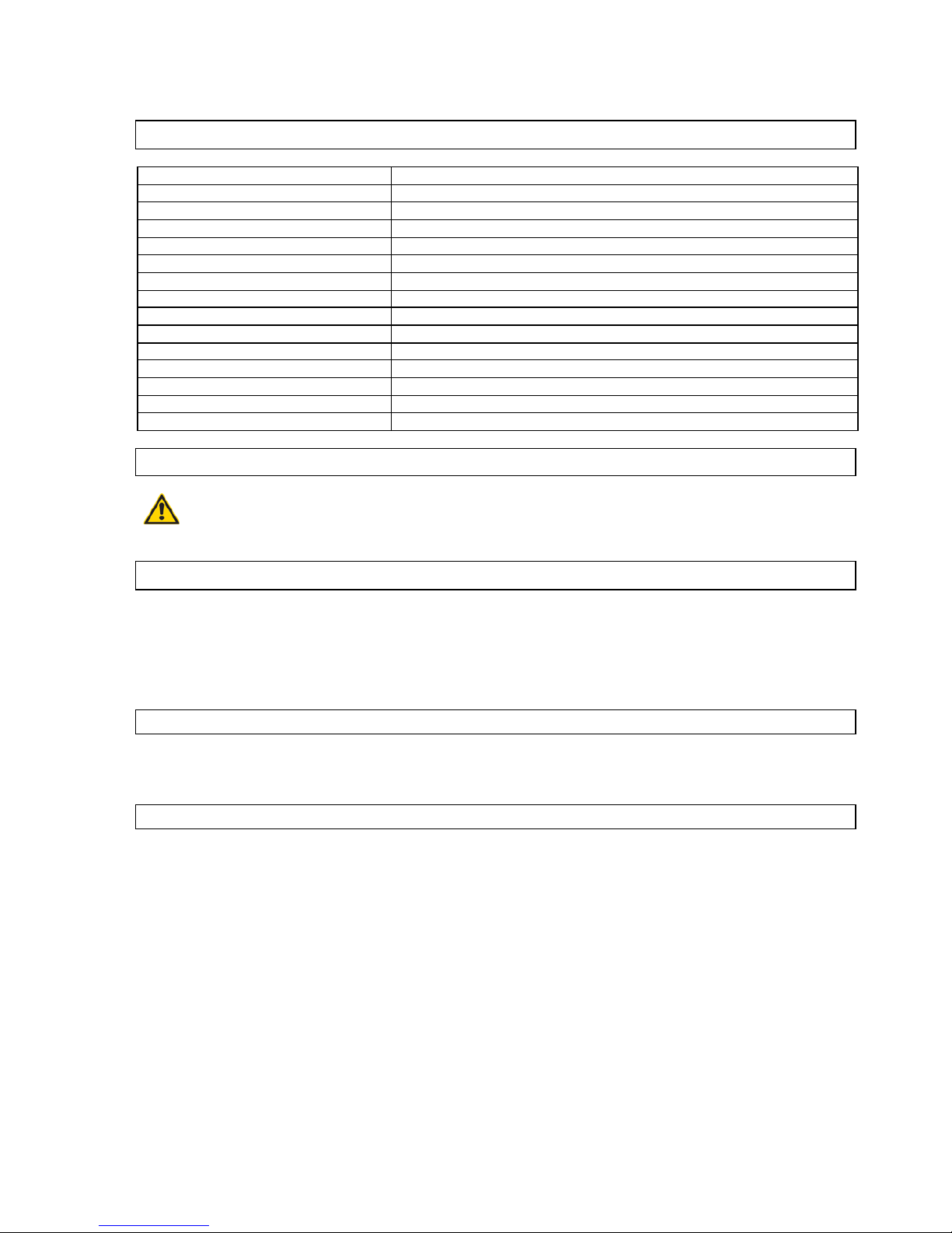
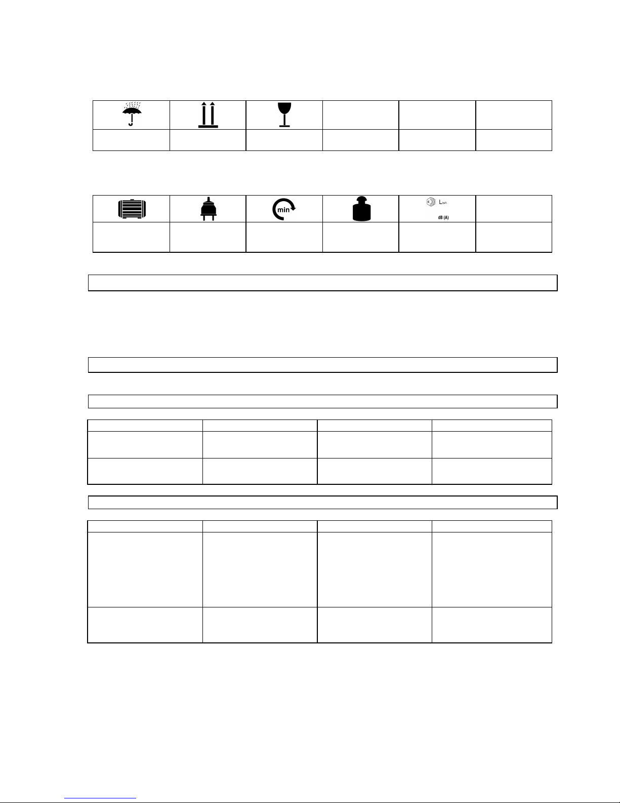
Fig. 1
Basically it is possible to sharpen saw discs of
diameter
80 mm - 700 m m .
Fix the disc on the feed slide. T he feed slide has
three centring hol es. A ccording to the centri ng
hole, it is pos sible to m ount va r iou s di am et e rs of
saw discs.
Fig. 2
First, s elect a c entri ng hol e and l oos en up t h e
clamping screw (Fig. 1b), now, the feed slide may
turn by 360°. With small diameters of the saw disc
it is recomm ended to use a centrin g hole (Fig . 2a),
on medium dia m eters, one of two a dd iti o na l ho l es.
Using a hand wheel, it is possible, upp er slide
may be adjusted. First loo sen clam ping scr ew out
(Fig. 1c). The diameter of the disc to be worked
ma y be set up aft er it i s loosened up.
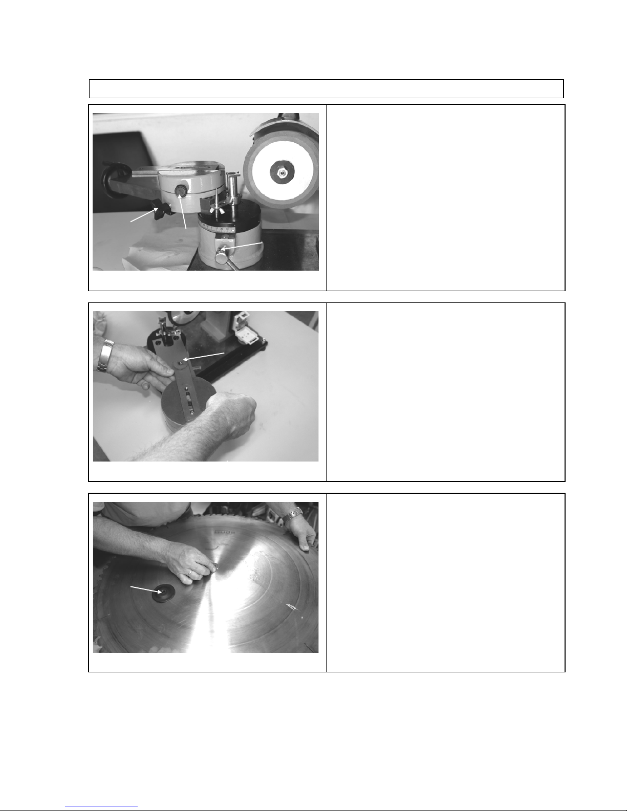
Fig. 3
When y ou find an a ppro pr iate distanc e between
the cent rin g hol e and the grin din g wheel , fix the
upper slide with clamping screw (Fig. 1c), Now,
the disc m ay be placed in the m i ddle of c en tr i ng
hole. Now, put a suitable adapt er in the saw disc
Put clamping disc (Fig. 3a) above the adapt er and
fix it with a screw.
TIP : Tighten the clamping scr ew so that the saw
disc m a y bet turned wi tho ut tak ing too m uc h
power.
c
a b a
a
22
Page 21

Fig. 4
First, det erm in e the cutting angle of shar p e nin g
the teeth inn er surfa ces. T he surfac es should be
parallel to the flat area of the grindi ng. Se arrow in
Fig.4 a nd Fig. 5 )
Fig. 5
Sha rpening i s done by s lidi ng th e s lide for war d
and backw ard. Min d th e s li de set up t o pr ovi de for
the hard metal sur fac e to be sharpened T he
oblong hole i n the sl id e work s a s a s top. (se e Fig .
6)
Fig. 6
Here, it is clear that the feed slide is set in parallel
to the grindi ng whee l and the sli d e goes to th e
stop, the gri nd ing w heel wor ks th e hard m etal
surface only . A lso, the set up to work smaller
grinding wheel.
Caution: Be very careful to move the saw disc on the slide in order to preven t any dam age of the
diam ond dis c!
a
23
Page 22
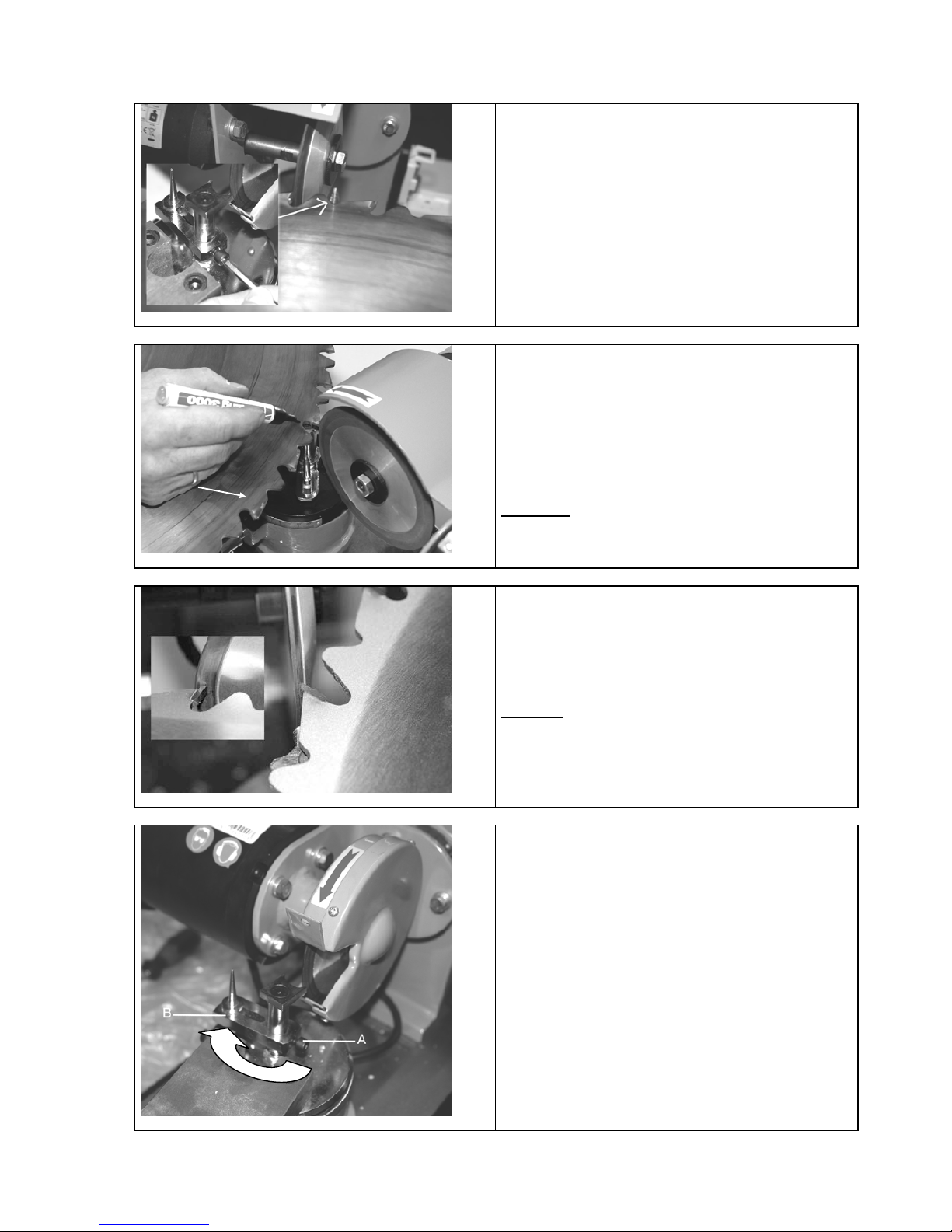
Fig. 7
A stop needl e shou l d be m ount ed on t o avoid
grinding th e saw di sc. It s hou ld be c ali b ra ted a nd
locked in place with a socket wrench .
Fig. 8
Teeth are marked with the selecto r pen which
makes the removal well reco gn isabl e and
controllable
If the grindin g wh e el a ngl e i s set up in the w ay
providing f or even gri n din g of t he inner s ur faces
of the teet h, the disc m a y be worked toot h by
tooth.
Caution: Always take the saw disc bec k
completely and avoid any jerky movem ents that
could dam a ge the grindi ng whe el.
Fig. 9
T he inclined fro nt side of t he gri nd i ng whee l is
used to sharpe n roo f-li ke cutti ng edg es. The
angles shou ld be deter m i ned and s et up in a n
appropriat ed way . In this case too, use the stop
pike to observe the final even diameter of the saw
disc.
Caution:
To m a ke turn of the too l s lide in the
positi on cor rec t f or grin din g ro of -lik e cutting
edges, it is necessa ry to turn the stop needl e to
the m otor side. (Fig. 9A )
Fig. 9A
To do that, socket screw should be loosened up
(Fig. 9A -
A ) and the stop nee dl e t urn ed on the s ide
of m otor.
a
24
Page 23
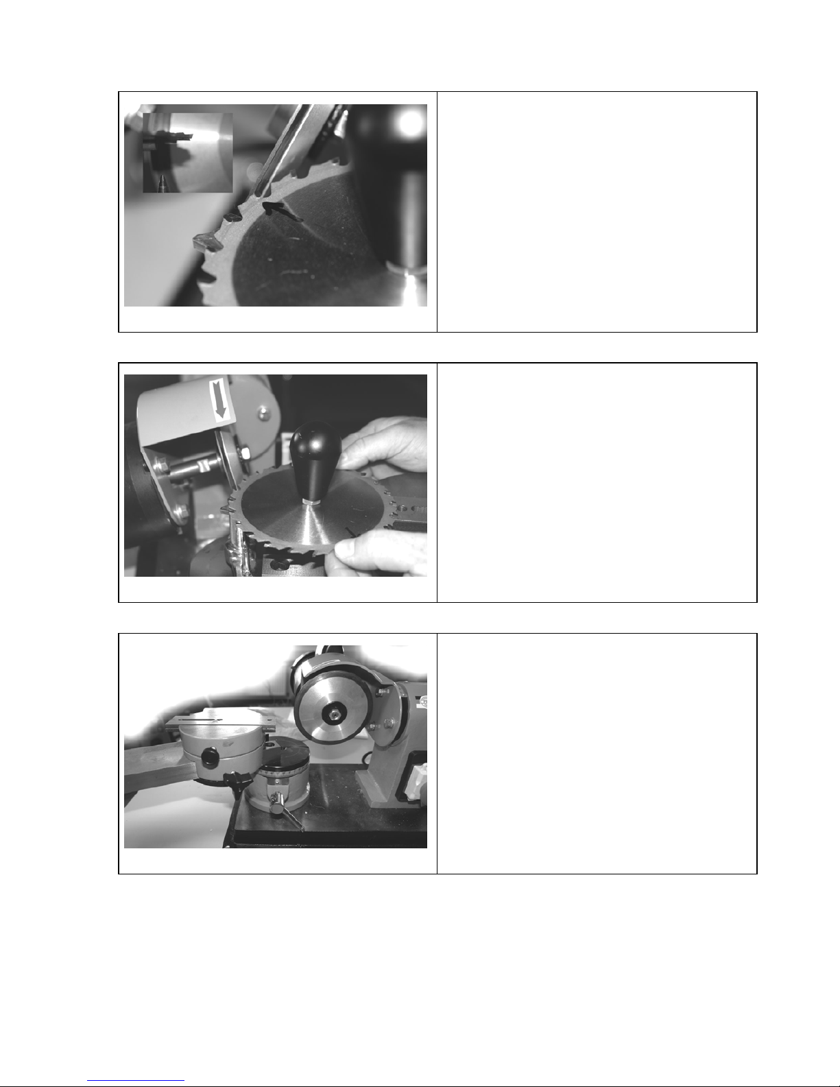
Fig. 10
With alternatin g teething, the grindin g wheel
should be ada pt ed to i nclina ti o n to the al t ern a ti ng
tooth (every othe r too th is shar p e ned )
Fig. 11
Set up the pre-
adjus ted angl e in reverse directi on .
It is possible to sharpen the remain in g teeth now.
Tip: Use a selector pen.
Fig. 12
If grinding small saw discs, it help s to remove
supportin g sc r ews. T hat s houl d be found out
individu all y ac cor din g t o th e sa w dis c and cuttin g
edge geometr y.
25
Page 24
6.1 Operator Safety Instructions
U npl ug the unit before any mai ntenance/adjus tm ent and repair . Unplug after fini shing the work as
well.
• Do not use the unit before you have read the operati ng m anual careful ly.
• Observe all the safety i nstructi ons indi cated in the m anual .
• Be responsible to t he others.
6.2 Step by Step Instructions
• Turn the slide with a clam ping hole to the required positi on according to the saw disc diameter. .
• Choose a suitable cl am ping adaptor and fix the disc in place.
• Set up the slide so that it is not possible to sharpen the di sc m is takenly w hen there is a hit on the
horiz ontal hol e.
• Mark the teeth internal surfaces with a black pen and put t he grinding wheel in the standstill on the area
to be ground.
• Sw itch the sharpening m achine and s crape the surface m arked i n black off to enable addi tional
calibration.
• Grind very carefully, ac cording to the s aw disc diam eter, one tooth aft er another.
• When grinding of all inner teeth areas are finis hed, grind evenl y the teeth sl opes on the inc lined area of
the disc using a stop to provide for eccentric run of the disc.
• Clean the unit carefully.
7 Troubles-Causes- Troubleshooting
Cauti on: A lway s check the overh eati ng protect ion first !
Trouble
Cause
T roubleshoo t in g
Burning di sc (blunt)
1. The sharpening surface ex c essiv e l y
lubricated.
2. Worn diam ond lay er.
1. Clean the uni t wit h the sharpening tool.
2. Replace the di sc
7.1.1 I nspecti ons and M aintenance
U npl ug the unit before any mai ntenance/adjus tm ent and cleani ng. U npl ug upon fini shing the work as
w ell Keep the machine cl ean and free of any dust. Oil the slide well to prevent jerking.
26
Page 25

7.2 Grinding Wheel Replacement
Fig. 13
To rep lace the wheel, l ock it on the spindl e at either
side with a fork ed wrench. T he l ock nut m a y be
loosene d or tigh t e ned in the dir ec ti on of the m otor
turning (clockwi se thr ead )
7.3 Inspections and Maintenance Safety Instructions
Only a unit mai ntained and cared for on a regular basis m ay be a serviceable ai d. I nsuff ici ent m aintenance
and care may result in emergenc ies and unforeseen ac cidents .
7.4 Inspections and Maintenance Schedule
Tim e Interval
Description
Other
Details if
Required
After every use
• Wipe the unit with clean dry cloth or blow off with low -pressure air .
8 Spare Parts
Claim s and orders of spar parts shal l be executed/satis fied in a fast m anner free of any
admi nistrati ve hinders i f a respecti ve servi cing form i s used. Dow nload the form at
http://www.guede.com/support
The form m ay also be requested from
Phone: +49 (0) 79 04 / 700-0
Fax: +49 (0) 79 04 / 700-250
E-Mail: info@guede.com
27
Page 26

1 Appareil
Affûteus e des lam es de scie robuste haute de gamm e. P our affûtage des l am es de sci e en métal dur de
diam ètre de 80 – 700 mm .
Disque abrasi f diam anté s pécial de 125 m m, 7 adaptateurs pour tous les di am ètres d’orif ice courants .
Affûtage profes sionnel de t outes les lam es de sc ies courantes de scie c irculai res m anuell es, sci e circul aires
de table, sci e à bois de chauffage, etc.
1.1 Contenu du colis
1. Roue m anuelle
2. Chariot coul iss ant
3. Disque d‘ appui
4. Vis de serrage
5. Aigui lle de butée
6. Levier de serrage du disque abrasi f
7. I nterrupteur d’arrêt d‘urge nce
8. Disque abrasi f
9. Vis d‘appui
10. Levier de serrage de la table d’appui
11. Levier de serrage du chariot supérieur
12. Levier de serrage du chariot couli ssant
13. Adaptateurs
13
29
Page 27

1.2 Garantie
La durée de la garantie est de 12 mois en cas d’une utili sati on industrielle et de 24 m ois pour le
consom m ateur final . La période de garantie com m enc e à courir à com pter de la date d’achat de l ’appareil.
La garantie s’appl ique ex c lusi vem ent sur les défauts de matériel ou des défauts de fabricati on. En cas de
réclamation pendant la durée de l a garantie, veui llez joindre l’ original du j ustifi cati f d’achat c om portant la
date d’achat.
La garantie ne couvre pas une utilisati on incom pétent e, tell e que surcharge de l’appareil , util isati on de force,
endomm agem ent par une personne étrangère ou un objet étranger , non respect du m ode d’em pl oi et du
mode de montage et usure normale.
2 Consignes générales de sécurité
Avant d’ util iser l’ appareil, l isez com plètem ent l a notice. Si vous avez des doutes sur le branchement et l a
mani pulati on de l’appareil , contac tez le fabri cant (servi ce après-vente).
AFIN D’ASSURER U N GRAND DEGR É DE SÉCURI TÉ, RESPECTEZ LES CON SIGNES SU IVANTES :
ATTENTIO N !
• L’appareil doit être fixé à l’établi de façon sûre, horizontale et solide.
• Le lieu de travail doit être propre et suffisamment éclairé (500 lux).
• N’utilisez pas l’appareil à proximité des matières, gaz et liquides inflammables.
• Portez des lunettes de protection, un casque et une tenue de protection adéquate. Si nécessaire, portez également
un masque.
• Portez toujours une tenue adéquate. Ne portez pas de v êtements larges ou bijoux pouvant s’accrocher aux pièces
en rotation. Il est également recommandé de porter des chaussures antidérapantes. Si v ous av ez des cheveux
longs, portez un filet.
• Veillez à maintenir une posture stable lors du trav ail.
• Éloignez les autres personnes, en particulier les enfants de votre lieu de travail.
• Laissez les dispositifs de protection existants à leur place et assurez leur parfait fonctionnement. Il est strictement
interdit de faire fonctionner l’appareil sans les dispositifs de protection.
• Contrôlez régulièrement le serrage correct de tous les boulonnages.
• Veillez à ce que le câble d’alimentation ne se trouve pas à proximité des pièces en rotation.
• Ne laissez pas l’appareil en marche sans surveillance. Si vous dev ez v ous éloigner de l’appareil, arrêtez-le.
• Si vous n’utilisez pas l’appareil, avant l’entretien/le nettoyage ou lors du remplacement d’un outil, retirez toujours la
fiche de la prise.
• Ne laissez aucun outil de réglage dans l’appareil. Av ant de le mettre en marche, v érifiez si v ous av ez retiré toutes
les clés et outils de réglage.
• En cas de pièces travaillées plus longues, utilisez un support.
• Évitez le contact des mains av ec l’abrasif.
•
• Veillez à ce que le disque abrasif ne cogne pas violemment la lame de scie ! Aucune garantie ne sera
allouée en c as d’end om m age m ent du dis que abra sif.
L’appareil doi t être ut ili sé uniquem ent sur un résea u élec tr i que é qu ip é de FI ( interr u pt eur de prote ct io n
contre le courant de défaut).
30
Page 28
2.1 Conduite en cas d’urgence
Effect uez les premi ers gestes de sec ours en foncti on de la blessure et appelez rapi dem ent les prem iers
secours.
Protégez l e blessé d’autres bles sures et calmez -le.
2.2 Indications figurant sur l’appareil
Explication des sym boles
Dans la notice et/ou sur l ’appareil figurent les sym boles suivant s:
Sé curité du prod ui t :
Produit répond aux
normes
correspondantes de la
CE
Interdic tio ns :
Interdi ction générale
(en c ombinaison avec
un autr e pict og r am me)
Défense de feu,
lumière ouverte et
défense de fumer
Défense de toucher
Défense
de tirer sur le
câble
Défense de toucher le s
pièces en rotation
N’ utilis ez pas l’appa r ei l
sous la pluie
A vertissement :
Avertissement/attention
Aver tiss ement : tens i o n
électr ique dangereuse
Respectez la distance
de sécurité
Consignes :
Port ez des lunettes de
protection
Utilisez un casque
Utilisez des gants de
protection
Avant toute
intervention, retirez la
fiche de la prise
Lisez la noti ce avant
l’utilisation.
Protection de l’en vir onnem en t :
Liquidez les d
éche ts d e
manièr e à ne pa s nuire
à l’environnem ent.
Déposez l’emballage
en carton au dépôt
pour recyclage.
Déposez les appareils
électriques ou
électroniques
défectueux et/ou
destinés à liquidation
au centre de
ramassage
correspondant.
Point vert – Duales
System Deutschland
AG
31
Page 29
Em ballage :
Prot égez de l’ hu m idité
Sens de pose Attention - fragile
Caractéristiqu es techniq u es :
Puissance moteur Fiche Tours/min Poids
Niveau de puissance
acoustique
2.3 Utilisation en conformité avec la destination
L’appareil doi t être util isé exclusiv em ent pour l’aff ûtage/le m eulage et pour l’usi nage des lam es de scie en
métal dur.
Le fabricant ne répond pas des dom m ages engendrés par le non respect des disposi tions des règlem ents
généraux en vigueur ains i que de cette not ice.
2.4 Dangers résiduels et mesures de protection
2.4.1 Dangers résiduel s m écaniques
Risque
Description
Mesure(s) de sécurité
D anger résiduel
Accrochage, enroulem ent
Des vêtements larges et bijoux
peuvent s’accrocher aux parties
en rotation.
Por tez toujours une tenue
adhérente et ne portez pas de
bijoux pouvant s ’acc roc her.
Frottement, écorchures
Le contact avec l’abrasif en
rotation peut prov oquer des
blessures graves.
Évitez le c ontact avec l’abrasif.
Portez des gants de protection.
2.4.2 Dangers résiduel s élect riques
Risque
Description
Mesure(s) de sécurité
D anger résiduel
Contact électrique direc t
Câbl e ou fiche défectueux peut
provoquer une électrocution.
Faites rem placer un câble ou
une fiche endomm agé par un
sp éc ialis t e. Utilise z l’app ar eil
uniquement avec un
interrupteur contr e le courant
de défaut (FI).
Contact électrique indirect
Blessures provoquées par des
pièces conductrices des pièces
de construction ouvertes ou
défectueuses.
Avant tout entretien, retirez la
fiche de la prise. Utilisez
l’appareil uniquement avec un
interrupteur contr e le courant
de défaut (FI).
32
Page 30

2.4.3 Dangers du bruit
Risque
Description
Mesure(s) de sécurité
D anger résiduel
Lésions de l‘ouïe
Un travail prolongé avec
l’appareil peut endommager
l’ouïe.
Portez toujours un casque de
protection.
2.4.4 Danger relatif aux mat ériaux et autres mat ières
Risque
Description
Mesure(s) de sécurité
D anger résiduel
Contact, aspiration
Une formation de poussières
trop importante peut
endommager les poumons.
Por tez toujours un mas que lors
du travail avec l’appareil.
2.4.5 Manquem ent aux princi pes ergonom iques
Risque
Description
Mesure(s) de sécurité
D anger résiduel
Utilisation négligée des
accessoires personnels de
protection.
Manipulation de l’appareil sans
accessoires de protection
adéquats peut c onduire aux
blessures externes ou internes
graves.
Por tez toujours une tenue de
protec tion adéquate, soy ez
prudents.
Éc lairage local insuf f is ant
Un éclairage insuffis ant
représente un grand risque.
Assurez toujours un éclairage
suffisant lors de la mani pulation
de l’appareil.
2.4.6 Autres dangers
Risque
Description
Mesure(s) de sécurité
D anger résiduel
Objets ou liquides éjectés
Lors de l’affûtage, de petites
particules d’abrasif peuvent
blesser vos yeux.
Por tez toujours des lunettes de
protection.
2.4.7 Liquidation
Les consignes de liqui dation résul tent des pi ctogram m es indi qués sur l’ appareil ou sur l ’em ball age. La
descripti on des signi ficat ions i ndividuel les s e trouve dans le c hapitre « Indicati ons sur l’ appareil ».
2.5 Opérateur
L’opérateur doit li re attentiv em ent la notic e avant d’ut ili ser l’apparei l.
2.5.1 Qualification
Mi s à part l’instruc tion détail lée par un spéc iali ste, aucune autre qual ific a tion spéc ifi qu e n’est requi se.
2.5.2 Âge minimal
L’appareil peut êt re utili sé uniquem ent par des personnes de plus de 16 ans .
Ex c eption faite des adolesc ents m anipul ant l’apparei l dans l e cadre de l’ens eignem ent profess ion nel s ous la
surveill ance du form ateur.
2.5.3 Formation
L’utilisation de l’appareil nécessi te uniquem ent l ’inst ruction par un spéci ali ste, éven tuel lem ent par l a notice.
U ne formation spéc iale n’ est pas néc essaire.
33
Page 31

3 Caractéristiques techniques
GSS 700 P
Prise :
230V/50 Hz
Fréquenc e / ty pe de prot ection :
IP 4 4
Classe de protection :
I
Puissance maximale P 1:
370 W/P 1/S6/40%
T ours m oteur :
280 min-1
Ø du disque abra si f en v iro n :
125 x 32 mm
A ngl e de réglag e du di sq u e a bras i f :
2 x 30°
A ngle de réglage de la table d’appu i :
30° à gauche/80° à droite
A dapt ateur pour le maintien de la
lame de scie :
35 mm, 30 mm, 28 mm, 25,4 mm, 25 mm, 18 mm, 16 mm
Câble d’alimenta tio n :
1,5 m/H 05 VV-F
Poi ds envi ro n :
38 kg
Niveau de puissance acous tiq ue :
73 dB (A )
Dim ensions L x L x H en mm :
670 x 390 x 310
N° de comm a nde
94220
4 Transport et stockage
L’appareil est conçu uniquemen t pour l’utilisatio n stationna ire.
Les outils non utilisés doi vent être rangés dans une pi èce sèche et f ermée.
5 Montage et première mise en service
L’appareil es t liv ré mont é, vous n’ avez qu’à le sortir de l’em ballage.
• Essuyez régulièrement les parties m étalli ques du chari ot couli ssant avec un chiffon i m bibé d’hui le et
graissez l’ax e avant chaque util isati on.
5.1 Consignes de sécurité relatives à la première mise en marche
• Veillez à ce que l’appareil soit correctem ent fixé à une surface adéquate.
• Veillez à ce que tous les boulonnages soient correct em ent s errés .
5.2 Procédé
• Montez les pièces i ndivi duelles dans l’ ordre indiqué. V eil lez à disposer correctem ent l es pièces de
constructi on en respectant les images.
34
Page 32

6 Manipulation
Fig. 1
L’appareil convient à l’affûtag e des lames de scie
dont le diamètre est compr is entre 80 m m et 700
mm.
Montez la lame de scie sur le chario t couli ss ant.
Le chariot coulissan t est équi pé de trois orifices
de c en tr ag e, dive rs diamèt r es de lames de scie
peuvent ê tre m ont és en fon ct io n du choi x de
l’orifice de centrag e.
Fig. 2
Tout d’abord, choissez l’orific e de centrag e
adéquat, desserrez la vis de serrage (fi g. 1b), le
chariot coulis sant peu t alors êtr e tourné de 360° .
Pour des lames de scies de petits diam ètres, no u s
recomm ando ns l ’orifice de cent rage fig. 2a, pour
des diamètres moy ens, l’un des deux autres
orifices. L e chariot supér ieur peu t être régl é à
l’aide de la roue m anuelle, pour cela , desserr ez
d’abord la vis de serra ge (fig. 1c). A près le
desserrag e de la vis de serrag e, il est possi bl e de
prérégler le diamèt r e pour la lame de scie à
affûter.
Fig. 3
Lorsque vous aurez trouvé la distance adéq uat e
entre l’orific e de centrag e et le disq ue abrasif,
fixez le chari ot supér ieu r à l’aide de la vi s de
serrage (fig. 1c). À présent, il est possib le de
placer la lame au centre de l’orifi ce de centra ge.
Placez l’adaptateu r adéqua t dans l’ori fic e de la
lame de scie.
Pl acez un disque d’ap pui sur l’ adap tat eur (fig . 3a)
et fixez-le à l ’aide de la vis de serrag e.
CONS EI L : Serrez la vis de serrag e de façon à ce
qu’il soit possibl e de tourner la lam e de scie sans
déployer une forc e excess ive.
c
a b a
a
35
Page 33

Fig. 4
T out d’abord, tro u vez l’ ang le de cou pe po ur
l’affûtage des surfa ces inter nes des dents, celles ci doivent se tro uver en parallèle par rappor t à la
surface plane du disqu e abrasif (voir flèche sur
les images 4 et 5)
Fig. 5
L’affûtage s’effectu e en déplaçan t le char iot
coulissant en avant et en arri ère. Il est néc essa ire
de veiller en mêm e temps que le chariot
coulissant soit réglé de façon à affût er
uniquement la surf ac e en métal dur, l’orifi ce
longitudinal dans le chari ot sert de butée
terminale (voir fig. 6)
Fig. 6
Ici l’on voit clairemen t que le chario t coulissa nt
est réglé para llèl em ent à la lame de scie et que le
chariot se déplace j usqu’à la buté e, le disque
abrasif affûte uniq uemen t la surf ac e en métal du r.
On voit également l e réglag e pou r une lam e de
scie de taille inf éri eure.
Attent ion : Déplacez la lame de scie sur le chariot avec une précau ti on maxim ale pour éviter
l’endomm a gem en t du di s qu e di am anté !
a
36
Page 34

Fig. 7
Pour ne pas affût er jusqu ’à la lam e de scie, il est
nécessaire de m onter l’aig uill e de butée. C elle-ci
doit être calib rée et bloquée à l’aide d’une clé
hexagonal e sur la vis d’appui.
Fig. 8
Marquer les dents à l’aide d’u n marqueu r, ce qui
permet de bien discerner et contrô ler la réductio n
du matériau.
Si l’angle du disq ue abras if est réglé de faço n à
affûter unifor mém ent les surfac es int ern es des
dents, il est possib le d’af fû ter les dent s de la lame
de scie l’une après l‘autre.
A ttention :
Reculez toujou r s complèt em ent l a la me
de scie et évitez des à-coups po uva nt
endommager le disque abra sif.
Fig. 9
Pour affûter des arêtes en toit, l’on utilis e la parti e
avant inclinée du disqu e abra sif. L es angles
doivent être réglés et bloqués de la m ême maniè r e
que lors de l’affûta ge des surfaces inter nes des
dents. L’utilisation de l’aiguil le de butée est
également néc essa ir e pour mainten ir uniforme le
diamètre final de la lame de scie.
A ttention :
Pour pou voir tou rn er le cha riot à la
position correc te pour l’affû tage des arê tes en
toit, il est nécessaire de tourn er l’ aiguill e de butée
vers le moteur (fig . 9A)
Fig. 9A
Pour cela, il est néc essai re de desser r er la vis
hexagonal e (fig. 9A -A ) et de tourner l’aigu ille de
butée vers le moteur !
a
37
Page 35

Fig. 10
Lorsqu’il s’agit d’une dentu r e alternée, il est
nécessaire d’ad ap ter le disqu e abrasif à
l’inclinaison de la dent alterné e (aff ûtage d’u n e
dent sur deux) .
Fig. 11
À présent, il est nécessair e de régler l’an gl e
préréglé dans le sens inver se. Maintena nt, il est
possible d’affûter les den ts restan tes .
Conseil : Utilisez le marqueur.
Fig. 12
Si vous devez affûter de petites lam es de scie, il
convient de déviss er les vis d’appu i. Cela dép end
de la lame de scie et de la géométr ie de l’arêt e.
38
Page 36

6.1 Consignes de sécurité relatives à la manipulation
Av ant tout entretien/régl age et répar ation , retirez l a fiche de l a prise. R etirez -la également à la fin de
l’intervention.
• Avant d’util iser l’ appareil, l isez attentivement l a notice.
• Respectez toutes l es consignes de sécurit é contenues dans l a notice.
• Comportez vous de façon responsabl e envers tierces pers on nes.
6.2 Notice étape par étape
• Tournez le chari ot couli ssant avec l‘ori fice de fi x ati on à la position souhai tée en foncti on du diam ètre de
la lame de scie.
• Choisissez l’adaptateur de fi x ati on adéquat et fixez la lame.
• Réglez le chariot de façon à évit er l’affûtage de l a lam e de scie en cas de choc sur l’ orific e longitudi nal.
• Marquez les surfaces internes des dents à l’ aide d’un m arqueur et pl acez le disque abrasi f au repos sur
la surface à affûter.
• Mettez l’affûteuse en m arche et raclez la surface m arquée en noir pour le cal ibrage final .
• À présent, affûtez prudem m ent l es dents l ’une après l’ autre en fonction du di am ètre de la lam e de scie.
• Lorsque toutes les surfaces i nternes des dents s ont biseautées, biseautez uniform ém ent les toi ts des
dents sur la surface incli née du disque à l ’aide de l a butée pour assurer la marche excentrée de la lam e.
• Nettoyez soigneusement l a m achine !
7 Pannes - causes - suppression
ATTENTION : CONTRÔLEZ D’ABORD LES FUSIBLES DE SURCHAUFF E !
Panne
Cause
Suppression
Le disque brûle
(émoussé)
1. Surface d’ affûtage trop graiss ée.
2. Couche diam antée us ée.
1. N ettoyez à l’aide de l’outil d’aff ûtage.
2. Remplacez le disque.
7.1.1 Révis ions et entreti en
Av ant tout entretien/régl age et répar ation , reti rez la fi che de la pris e. Reti rez -la également à la fi n de
l’intervention.
M ai ntenez l’appareil propre et sans poussières .
Grai ssez suffisam m ent l e chariot couliss ant pour éviter l es à-coups.
39
Page 37

7.2 Remplacement du disque abrasif
Fig. 13
Pour remplac er le disque abrasif , bl oq uez le double
cy lindre sur l’arbre de moteur à l’ aide d’une clé à
fourche puis desser rez ou resserrez l ’écrou de sûreté
sur l’arbre de moteur en tournant dans le sens des
rotations du mote ur (fil et age à droit e nor m a l).
7.3 Consignes de sécurité relatives aux révisions et à l’entretien
Seul un appareil régulièrem ent entretenu et traité peut donn er sati sfacti o n. U n entreti en insuff isant peut
engendrer des accidents et des bless ures.
7.4 Plan des révisions et de l’entretien
Intervalle de
temps
Description
Autres
détails
Après chaque utilisation
• Nettoyez l’appareil à l’aide d’un chiffon propre et sec ou soufflez-le à l’aide de l’air
comprimé à basse pression.
8 Pièces détachées
Toutes les récl amat ions et c om mandes de pièces détachées seront rapidem ent trai té es à
l’aide du formul aire corresponda nt s ur :
http://www.guede.com/support
Vous pouvez égalem ent dem ander ce form ulai re ici :
Tél.: +49 (0) 79 04 / 700-0
Fax: +49 (0) 79 04 / 700-250
E-Mail: info@guede.com
40
Page 38

1 Přístroj
Masivní ostřička pilových kotoučů nejvyšší třídy. K ostření pilových kotoučů z tvrdokovu o průměru
80 – 700 m m .
Speciální diamantový brusný kotouč 125 mm, 7 adaptérů pro všechny běžné průměry vrtání.
Profesionální ostření všech běžných pilových kotoučů ručních kotoučových pil, stolních kotoučových pil, pil
na palivové dřevo atd.
1.1 Objem dodávky
1. Ruční kolečko
2. Podávací saně
3. Přítlačný kotouč
4. Svěrací šroub
5. Doraz ová j ehla
6. Svěrací páka brusného kotouče
7. Nouzový vypínač
8. Brusný kotouč
9. Opěrný šroub
10. Svěrací páka opěrného stolu
11. Svěrací šroub vrchních saní
12. Svěrací šroub podávacích saní
13. Adaptéry
13
42
Page 39

1.2 Záruka
Záruční doba činí 12 měsíců při průmyslovém použití, 24 měsíců pro spotřebitele a začíná dnem nákupu
přístroje.
Záruka se vztahuje výhradně na nedostatky způsobené vadou materiálu nebo výrobní vadou. Při reklamaci v
záruční době je třeba přiložit originální doklad o koupi s datem prodeje.
Do záruky nes padá neodborné použití jako např. přetížení přístroje, použití násilí, poškození cizím zásahem
nebo cizími předměty, nedodržení návodu k použití a montáži a normální opotřebení.
2 Všeobecné bezpečnostní pokyny
Návod k obsluze je třeba před prvním použitím přístroje kompletně přečíst. Pokud nastanou o zapojení a
obsluze přístroje pochybnosti, obraťte se na výrobce (servisní oddělení).
ABY BYL ZARUČEN VYSOKÝ STUPEŇ BEZPEČNOSTI, DODRŽUJTE POZORNĚ NÁSLEDUJÍCÍ
POKYNY:
POZOR!
• Přístroj musí být bezpečně, vodorovně a pevně připevněn k pracovnímu stol u.
• Pracoviště musí být čisté a dostatečně osvětlené (500 lux).
• Přístroj nepoužívejte nikdy v blízkosti hořlavých materiálů, plynů a kapalin.
• Noste ochranné brýle, chrániče uší a vhodný ochranný oděv. V případě nutnosti noste nav í c respirátor.
• Noste vždy vhodný oděv. Nenoste široký oděv ani šperky, mohly by být zachyceny rotujícími částmi. Doporučuje se
neklouzavá obuv. Máte-li dlouhé vlasy, noste síťku na vlasy.
• Při prác i s přístrojem dbejte vždy na stabilní postoj.
• Ostatní osoby, především děti, držte mimo dosah pracoviště.
• Stávající ochranná zařízení nechte zásadně na svém místě a zajistěte jejich bezvadnou funkci. Provoz bez
ochranného zařízení je zásadně zakázán.
• Kontrolujte pravidelně, zda jsou všechna šroubení pevně namontovaná.
• Ujistěte se, že se napájecí kabel nenachází v blízkosti rotujícíc h částí.
• Přís troj v chodu nenechávejte bez dozoru. Pokud odcházíte od přístroje, zásadně jej vypněte.
• Pokud přístroj nepoužíváte, před údržbou/čištěním nebo při výměně nástroje vytáhněte vždy zástrčku.
• V přístroji nenechávejte zastrčené žádné seřizovací klíče. Před zapnutím kontrolujte, zda byly odstraněny klíče a
seřizovací nástroje.
• U delších obrobků je třeba používat opěru.
• Zabraňte kontaktu svých rukou s brusivy.
•
• Dbejte na to, aby brusný kotouč nikdy tvrdě nenarazil na pilový kotouč! Za poškození diamantového
kotouče nelze poskytnout záruku.
Přístroj se smí používat jen v elektrické síti s FI (ochranný vypínač proti chybovému proudu).
43
Page 40

2.1 Chování v případě nouze
Zaveďte úrazu odpovídající potřebnou první pomoc a vyzvěte co možná nejrychleji kvalifikovanou lékařskou
pomoc.
Chraňte zraněného před dalšími úrazy a uklidněte jej.
2.2 Označení na přístroji
Vysvětlení symbolů
V tomto návodu a/nebo na přístroji jsou použity následující symboly:
Bezpečnost produktu:
Produkt odpovídá
příslušným normám EU
Zákazy:
Všeobecný zákaz
(ve spojení s jiným
piktogramem)
Zákaz ohně,
otevřeného světla a
kouření
Zákaz dotyku
Zákaz tahání za kabel
Nedotýkejte se
rotujících dílů
Přístroj nepoužívejte za
deště
Výstraha:
Výstraha/ pozor
Výstraha před
nebezpečným
elektrickým napětím
Dodržujte
bezpečnostní odstup
Příkazy:
Používej te ochranné
brýle
Používej te sluchátka
Používej te ochranné
rukavice
Před otevřením
vytáhněte zástrčku
Před použitím si
přečtěte návod k
obsluze
Ochrana životního prostředí:
Odpad zlikvidujte
odborně tak, abyste
neškodili životnímu
prostředí.
Obalový materiál
z
lepenky lze ode v zdat
za účelem recyklace do
sběrny.
Vadné a/nebo
likvidované elektrické či
elektronické přístroje
mus í bý t odevz dá ny d o
příslušných sběren.
44
Page 41

Obal:
Chraňte před vlhkem
Obal musí směřovat
nahoru
Pozor - kř e h ké
Technické úda je:
Výkon motoru Přípojka Otáčky za minutu Hmotnost
Hladina akustického
výkonu
2.3 Použití v souladu s určením
Přístroj se smí používat výlučně k broušení/ostření a obrábění pilových kotoučů z tvrdokovu.
Při nedodržení ustanovení, z všeobecně platných předpisů, jakož i z tohoto návodu, nelze činit výrobce
odpovědným za škody.
2.4 Zbytková nebezpečí a ochranná opatření
2.4.1 Mechanická zbytková nebezpečí
Ohrožení
Popis
Ochranné(á) opatření
Zbytkové nebezpečí
Zachycení, navinutí
Široký oděv a šperky mohou
být zachyceny rotujícími částmi.
Noste vždy přiléhavý oděv a
nenoste šperky, které by mohly
být zachyceny.
Tření, oděr
Kontakt s rotujícím brusivem
může vést k vážným úrazům.
Zabraňte vždy kontaktu
s brus ivem. Noste ochranné
rukavice.
2.4.2 Elektrická zbytková nebezpečí
Ohrožení
Popis
Ochranné(á) opatření
Zbytkové nebezpečí
Přímý elektrický kontakt
Vadný kabel nebo zástrčka
může způsobit úder elektrickým
proudem.
Nechte v adné kabely nebo
zástrčky vyměnit vždy
odborníkovi. Přístroj používejte
jen na přípojce s ochranným
vypínačem proti chybovému
proudu (FI).
Nepřímý elektrický kontakt
Poranění vodivými součástmi u
otevřených elektrických nebo
vadných konstrukčních dílů.
Při údržbě vy táhněte vždy
zástrčku.
Přístroj používejte jen na
přípojce s ochranným
vypínačem proti chybovému
proudu (FI).
45
Page 42

2.4.3 Ohrož ení hlukem
Ohrožení
Popis
Ochranné(á) opatření
Zbytkové nebezpečí
Poškození sluchu
Delší práce s přístrojem může
poškodit sluch.
Noste vždy chrániče uší.
2.4.4 Ohrož ení m ateriály a jiným i látkami
Ohrožení
Popis
Ochranné(á) opatření
Zbytkové nebezpečí
Kontakt, vdechnutí
Při velké prašnosti mohou být
poškozeny plí ce..
Při pr ác i s přístrojem noste
vždy respirátor.
2.4.5 Zanedbání ergonomick ých z ás ad
Ohrožení
Popis
Ochranné(á) opatření
Zbytkové nebezpečí
Nedbalé použ ív ání osobních
ochranných pomůcek
Obsluha přístroje bez
odpovídajících ochranných
pomůcek může vést k vážným
vnějším i vnitřním poraněním.
Noste vždy předepsaný
ochranný oděv a pracujte
rozvážně.
Nepřiměřené lokální osvětlení
Nedostatečné osvětlení
představuje vysoké
bezpečnostní riziko.
Při pr ác i s přístrojem zajistěte
vždy dostatečné osvětlení.
2.4.6 Ostatní ohrož ení
Ohrožení
Popis
Ochranné(á) opatření
Zbytkové nebezpečí
Odhozené předměty či stříkající
kapaliny
Při broušení mohou drobné
částečky brusiva nebo média
poškodit V aše oči.
Při práci noste vždy ochranné
brýle.
2.4.7 Likvidace
Pokyny pro likvidaci vyplývají z piktogramů umístěných na přístroji resp. obalu. Popis jednotlivých významů
najdete v kapitole „Označení na přístroji“.
2.5 Požadavky na obsluhu
Obsluha si musí před použitím přístroje pozorně přečíst návod k obsluze.
2.5.1 Kvalifikace
Kromě podrobného poučení odborníkem není pro používání přístroje nutná žádná speciální kvalifikace.
2.5.2 Minimální věk
Na přístroji smí pracovat jen osoby, jež dosáhly 16 let.
Výjimku představuje využití mladistvých, pokud se toto děje během profesního vzdělávání za účelem
dosaž ení dovednos ti pod dohledem š koli tele.
2.5.3 Školení
Používání přístroje vyžaduje pouze odpovídající poučení odborníkem resp. návodem k obsluze. S peci ální
školení není nut né.
46
Page 43

3 Technické údaje
GSS 700 P
Přípojka:
230V/50 Hz
Frekvence / ty p ochrany :
IP 4 4
Třída ochrany:
I
Max. výkon P1:
370 W/P 1/S6/40%
Otáčky motoru:
280 min-1
Ø brusného kotouče cca:
125 x 32 mm
Seřizovací úhel brusného kotouče:
2 x 30°
Seřizovací úhel opěrného stolu:
30° vlevo/80° vpra vo
A dapt ér pro úchy t pi lové h o
kotouče:
35 mm, 30 mm, 28 mm, 25,4 mm, 25 mm, 18 mm, 16 mm
Připojovací kab el:
1,5 m/H 05 VV-F
Hmotnost cca:
38 kg
Hladina akustického výkonu:
73 dB (A )
Rozměry D x Š x V v mm:
670 x 390 x 310
Obj. č.:
94220
4 Přeprava a skladování
Přístroj je koncipován jen pro stacionární použití.
N epouž ív ané nástroje musí bý t uloženy v suché, uzamčené místnosti.
5 Montáž a první uvedení do provozu
Přístroj se dodává smontovaný, musíte ho jen vyjmout z obalu.
• Kovové součásti posuvných saní otírejte pravidelně hadrem napuštěným olejem a namažte před každým
použitím vřeteno.
5.1 Bezpečnostní pokyny pro první uvedení do provozu
• Dbejte na bezpečné připevnění přístroje k vhodném u povrc hu.
• Ujistěte se, jsou-li v šechna šroubení ut až ená.
5.2 Postup
• Proveďte montáž jednotlivých dílů ve znázorněném pořadí. Přitom dbejte na správné uspořádání
konstrukčních dílů dle obrázků.
47
Page 44

6 Obsluha
Obr. 1
Zásadně lze ostřit průměr pilového kotouče
80 mm až 700 mm .
Pilový kotouč se namontuje na podávací saně.
Podávací saně mají tři centrovací otvory, podle
volby centrovacího otvoru lze montovat různé
průměry pilových kotoučů.
Obr. 2
Nejprve zvolte vhodný centrovací otvor, přičemž
povolte svěrací šroub (obr. 1b), podávací saně lze
nyní pootočit o 360°. U malých průměrů pilového
kotouče se doporučuje centrovací otvor (obr. 2a),
u středních prů
měrů jeden ze dvou dalších otvorů.
Pomocí ručního kolečka lze nastavit i vrchní saně,
přičemž povolte nejprve svěrací šroub (obr. 1c).
Po povolení svěracího šroubu lze přednastavit
průměr pro pilový kotouč, který má být broušen.
Obr. 3
Pok ud jste našli vhodnou vzdálenost mezi
centrovacím otvorem a brusným kotoučem, vrchní
saně se zafixují svěracím šroubem (obr. 1c), nyní
lze kotouč položit na střed centrovacího otvoru.
Ny ní vložte vh od ný adapt ér do otvor u pi lového
kotouče.
Nad a daptér se ny ní pol o
ží přítlačný kotouč (obr.
3a) a připevní svěracím šroubem.
TIP: Svěrací šroub utáhněte jen tak, aby šlo pilový
kotouč pootočit bez vynaložení velké síly.
c
a b a
a
48
Page 45

Obr. 4
Nejprve zjistěte úhel řezu k
ostření vnitřních ploch
zubů, tyto musí stát přesně paralelně k rovné
ploše brusného kotouče. (viz šipka na obr.4 a obr.
5)
Obr. 5
Ostření probíhá posouváním podávacích saní
dopředu a dozadu, přičemž je třeba dbát na to,
aby byly podávací saně nastaveny tak, aby byl
naostřen jen povrch z tvrdokovu, podé l ný otvor
v saních slouží jako koncový do raz. (viz obr. 6)
Obr. 6
Zde je jasně vidět, že podávací saně jsou
nastaveny paralelně k brusnému kotouči a saně
jedou na doraz, brusný kotouč brousí jen povrch z
tvrdokovu. Rovněž je jasně vidět nastavení pro
menší pilový kotouč.
Pozor: Pilovým kotoučem pohybujte na saních maximálně opatrně, abyste zabránili poškození
diamantového kotouče!
a
49
Page 46

Obr. 7
Abyste nebrousili do pilového kotouče, musí být
namontována dorazo vá jehla. T ato se kalibruje a
zaare
tuje imbusovým klíčem na opěrném šroubu.
Obr. 8
Selektorovým perem se označí zuby pily, tak lze
dobře rozpoznat a kontrolovat úběr materiálu.
Je-
li úhel brusného kotouče nastaven tak, že jsou
vnitřní plochy zubu rovnoměrně broušeny, lze
pilový koto uč ostřit zub po zubu.
Pozor:
Pilovým kotoučem jeďte vždy zcela zpět a
vyhněte se trhavým pohybům, které by mohly
poškodit brusný kotouč.
Obr. 9
K ostření střechových břitů se používá šikmá
přední strana brusného kotouče, úhly je stejně
jako u vnitřních ploch zubů třeba zjistit a
odpovídajícím způsobem nastavit. Také zde
pracujte s
doraz ovým t rnem , abyste m ohli dod rž e t
rovnoměrný konečný průměr pilového kotouče.
Pozor:
Aby bylo možné otočit nástrojové saně do
správné pol o hy pro broušení střechových bř
itů, je
nutné otočit dorazovou jehlu na stranu motoru.
(obr. 9A)
Obr. 9A
K tom u m usí být povolen i m buso vý šro ub (ob r.
9A-
A) a dorazová jehla otočena na stranu motoru!
a
50
Page 47

Obr. 10
U střídavého ozubení musí být brusný kotouč
přizpůsoben sklonu střídavého z ubu (bro usí se
každý druhý zub).
Obr. 11
Nyní se nastaví přednastavený úhel v opačném
směru. Nyní lze naostřit zbylé zuby.
Tip: Pracujte se sel ektoro vý m perem .
Obr. 12
Pokud brousíte malé pilové kotouče, je vhodné
vyšroubovat opěrné šro uby. Toto musíte
individuálně zjistit podle pilového kotouče a
geometrie břitu.
51
Page 48

6.1 Bezpečnostní pokyny pro obsluhu
Před každou údržbou/seřizováním a opravami vytáhněte zástrčku. Zástrčku vytáhněte i po skončení
práce.
• Použijte přístroj až poté, co jste si pozorně přečetli návod k obsluze.
• Dodržujt e všechny v návodu uvedené bezpečnostní pokyny.
• Chovejte se zodpovědně vůči ostatním osobám.
6.2 Návod krok za krokem
• Posuvné saně s úchytným otvorem otočte podle průměru pilového kotouče do potřebné polohy.
• Zvolte vhodný uchycovací adaptér a kotouč zafixujte.
• Saně nastavte tak, aby při nárazu na podélný otvor nešlo omylem brousit kotouč.
• Vnitřní plochy zubů označte černou tužkou a brusný kotouč v klidovém stavu položte čistě na plochu,
která se m á brousit.
• Nyní ostřičku zapněte a černě označenou plochu kvůli konečné kalibraci seškrábněte.
• Nyní bruste podle průměru pilového kotouče velice opatrně jeden zub po druhém.
• Jsou-li zbroušeny všechny vnitřní plochy zubů, zbruste rovnoměrně střechy zubů na šikmé ploše
kotouče pomocí dorazu, aby byl zaručen výstředný běh kotouče.
• Stroj poté důkladně vyčistěte!
7 Poruchy - Příčiny - Odstranění
POZOR: KONTROLUJTE VŽDY NEJPRVE POJISTKY PROTI PŘEHŘÁTÍ!
Porucha
Příčina
Odstranění
Kotouč hoří (tupý)
1. Příliš namazaná ostřicí plocha.
2. Opotřebená diamantová vrstva.
1. Vyčistěte nástrojem na ostření.
2. Kotouč vyměňte.
7.1.1 Prohlídk y a údrž ba
Před každou údržbou/seřizováním a čištěním vytáhněte zástrčku. Zástrčku vytáhněte i po skončení
práce.
Přístroj udržujte vždy čistý a bez prachu.
Posuvné saně dobře namažte olejem, aby se zabránilo trhavým pohybům.
52
Page 49

7.2 Výměna brusného kotouče
Obr. 13
K
výměně brusného kotouče se dvouhran zaaretuje na
hřídeli motoru rozvidleným klíčem, nyní lze pojistnou
matici na hřídeli motoru povo lit neb o utá hnout v e
směru otáčení motoru (normální pravotočivý závit).
7.3 Bezpečnostní pokyny pro prohlídky a údržbu
N Jen pravidelně udržovaný a ošetřovaný přístroj může být uspokojivou pomůckou. Nedostatečná údržba a
péče může vést k nepředvídaným nehodám a úrazům.
7.4 Plán prohlídek a údržby
Časový interval
Popis
Příp. další
detaily
Po kaž dém použití
• Přístroj otřete čistým, suchým hadrem nebo of oukejte tlakovým vzduchem při
nízkém tlaku.
8 Náhradní díly
Reklamace a objednávky náhradních dílů budou rychle a nebyrokratickou cestou vyřízeny
pomocí příslušného servisního formuláře na
http://www.guede.com/support
Tento formulář si lze vyžádat i na
Tel.: +49 (0) 79 04 / 700-0
Fax: +49 (0) 79 04 / 700-250
E-Mail: info@guede.com
53
Page 50

1 Prístroj
Masívna ostrička pílových kotúčov najvyššej triedy. Na ostrenie pílových kotúčov z tvrdokovu s priem erom
80 – 700 mm.
Špeciálny diamantový brúsny kotúč 125 mm, 7 adaptérov pre všetky bežné priemery vŕtania.
Profesionálne ostrenie všetkých bežných pílových kotúčov ručných kotúčových píl, stolových kotúčových píl,
píl na palivové drevo atď.
1.1 Objem dodávky
1. Ručné koliesko
2. Podávaci e sane
3. Prítlačný kotúč
4. Zvieracia skrutka
5. Doraz ová i hla
6. Zvieracia páka brúsneho kotúča
7. Núdzový vypínač
8. Brúsny kotúč
9. Oporná skrutka
10. Zvieraci a páka oporného stol a
11. Zvieracia skrutka vrchných saní
12. Zvieraci a skrutka podáv acích saní
13. Adaptéry
13
55
Page 51

1.2 Záruka
Záručná lehota je 12 mesiacov pri priemyselnom použití, 24 mesiacov pre spotrebiteľa a začína dňom
nákupu prístroja.
Záruka sa vzťahuje výhradne na nedostatky spôsobené chybou materiálu alebo výrobnou chybou. Pri
reklamácii v záručnej lehote je potrebné priložiť originálny doklad o kúpe s dátumom predaja.
Do záruky nepatrí neodborné použiti e, ako napr. preťaženie prístroja, použitie násilia, poškodenie cudzím
z ásahom alebo cudz ím i predmetm i, nedodržani e návodu na použ i tie a m ontáž a norm álne opotrebenie.
2 Všeobecné bezpečnostné pokyny
Návod na obsluhu je potrebné pred prvým použitím prístroja kompletne prečítať. Ak nastanú o zapojení a
obsluhe prístroja pochybnosti, obráťte sa na výrobcu (servisné oddelenie).
ABY BOL ZARUČENÝ VYSOKÝ STUPEŇ BEZPEČNOSTI, DODRŽUJTE POZORNE NASLEDUJÚCE
POKYNY:
POZOR!
• Prístroj musí byť bezpečne, vodorovne a pevne pripevnený k pracovnému stolu.
• Pracovisko musí byť čisté a dostatočne osvetlené (500 lux).
• Prístroj nepoužívajte nikdy v blízkosti horľavých materiálov, plynov a kvapalín.
• Noste ochranné okuliare, chrániče uší a vhodný ochranný odev. V prípade nutnosti noste navyše respirátor.
• Noste vždy vhodný odev. Nenoste široký odev ani šperky, mohli by byť zachytené rotujúcimi časťami. Odporúča sa
protišmykov á obuv. Ak máte dlhé vlasy, noste sieťku na vlasy.
• Pri práci s prístrojom dbajte v ždy na stabilný postoj.
• Ostatné osoby, predovšetkým deti, držte mimo dosahu pracoviska.
• Existujúce ochranné zariadenia nechajte zásadne na sv ojom mieste a zaistite ich bezchybnú funkciu. Prevádzka
bez ochranného zariadenia je zásadne zakázaná.
• Kontrolujte pravidelne, či sú všetky skrutkové spoje pevne namontované.
• Uistite sa, že sa napájací kábel nenachádza v blízkosti rotujúcich častí.
• Prístroj v chode nenechávajte bez dozoru. Ak odchádzate od prístroja, zásadne ho v ypnite.
• Ak prístroj nepoužívate, pred údržbou/čistením alebo pri výmene nástroja vytiahnite vždy zástrčku.
• V prístroji nenechávajte zastrčené žiadne nastavovacie kľúče. Pred zapnutím kontrolujte, či boli odstránené kľúče a
nastav ovacie nástroje.
• Pri dlhších obrobkoch je potrebné používať oporu.
• Zabráňte kontaktu svojich rúk s brúsivami.
•
• Dbajte na to, aby brúsny kotúč nikdy tvrdo nenarazil na pílový kotúč! Za poškodenie diamantového kotúča
nie je možné poskytnúť záruku.
Prístroj sa sm ie použ ívať len v elektrickej sieti s FI (ochranný vypínač proti chybovému prúdu).
56
Page 52
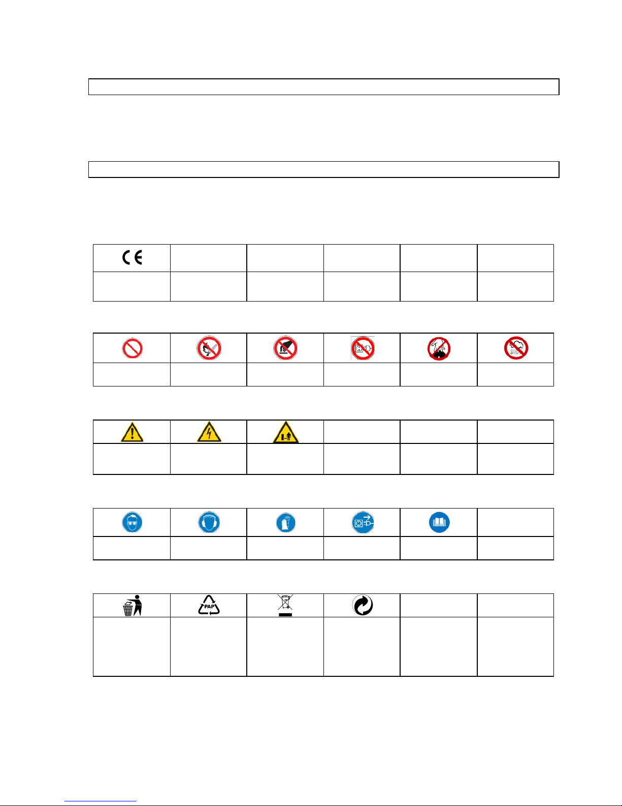
2.1 Správanie v prípade núdze
Zaveďte úrazu zodpovedajúcu potrebnú prvú pomoc a vyzvite čo možno najrýchlejšie kvalifikovanú lekársku
pomoc.
Chráňte zraneného pred ďalšími úrazmi a upokojte ho.
2.2 Označenia na prístroji
Vy svetlenie sy m bolov
V tom to návode a/alebo na prístroji s ú použ ité nas ledujúc e sym boly :
Be zpečnosť produktu:
Produkt zodpovedá
prí s lušný m nor m á m E Ú
Zákazy:
Všeobecný zákaz
(v spojení s iným
piktogramom)
Zákaz ohňa,
otvoreného svetla a
fajčenia
Zákaz dotyku
Zákaz ťahania za kábel
Nedotýkajte sa
rotujúcich dielcov
Prístroj n
epouž íva j t e za
dažďa
Výstraha:
Výstraha/pozor
Výstraha pred
nebezpečným
elektrickým napätím
Dodržujte
bezpečnostný odstup
Príkazy:
Používaj te ochranné
okuliare
Používaj te slúchadlá
Používaj te ochranné
rukavice
Pred otvorením
vytiahnite zástrčku
Pred použi tím si
prečítajte návod na
obsluhu
Ochrana životn ého pro stred ia:
Odpad zlikvidujte
odborne tak, aby ste
neškodili životnému
prostrediu.
Obalový materiál
z lepenky j e m ožné
odovzdať za účelom
recyklácie do zberne.
Chybné a/al ebo
likvidované elektrické či
elektronické prístroje
musia byť odovzdané
do prísl ušných zberní.
Zelený bod–Duales
System Deutschland
AG
57
Page 53

Obal:
Chráňte pred vlhkom
Obal musí smerovať
hore
Pozor - kre hké
Technické úda je:
Výkon motora Prípojka Otáčky za minútu Hmotnosť
Hladina akustického
výkonu
2.3 Použitie v súlade s určením
Prístroj sa smie používať výlučne na brúsenie/ostrenie a obrábanie pílových kotúčov z tvrdokovu.
Pri nedodržaní us tanovení, z všeobecne platný ch predpisov, ako aj z tohto návodu, nie je možné činiť
výrobcu z odpov edným z a škody.
2.4 Zvyškové nebezpečenstvá a ochranné opatrenia
2.4.1 Mechanické zvyškové nebezpečenstvá
Ohrozenie
Popis
Oc hranné opatrenia
Zvyškové nebe zpeče nstvá
Zac hytenie, nav inutie
Široký odev a šperky môžu byť
zachytené rotujúcimi časťami.
Noste vž dy pr iliehavý odev a
nenoste šperky, ktoré by mohli
byť zachytené.
Trenie, oder
Kontakt s rotujúcim brúsivom
môže viesť k vážnym úrazom.
Zabráňte vždy kontaktu
s brús ivom. Noste ochranné
rukavice.
2.4.2 Elektrické zvyškové nebezpečenstvá
Ohrozenie
Popis
Oc hranné opatrenia
Zvyškové nebe zpeče nstvá
Pr iamy elektrický kontakt
Chybný kábel alebo zástrčka
môže spôsobiť úder elektrickým
prúdom.
Nechajte chybné káble alebo
zástrčky vymeniť vždy
odborníkovi. Prís troj používajte
len na prí pojke s ochranným
vypínačom proti chybovému
prúdu (FI).
Nepriamy elektrický kontakt
Poranenie vodivými súčasťami
pri otvorených elektrických
alebo chybných konštrukčných
dieloch.
Pri údržbe vytiahnite vždy
zástrčku.
Pr ís troj používajte len na
prípojke s ochranným
vypínačom proti chybovému
prúdu (FI).
58
Page 54

2.4.3 Ohroz enie hluk om
Ohrozenie
Popis
Oc hranné opatrenia
Zvyškové nebe zpeče nstvá
Poškodenie sluchu
Dlhšia práca s prístrojom môže
poškodiť sluch.
Noste vždy chrániče uší.
2.4.4 Ohroz enie m ateriál m i a inými látkam i
Ohrozenie
Popis
Oc hranné opatrenia
Zvyškové nebe zpeče nstvá
Kontakt, vdýc hnutie
Pri veľkej prašnosti môžu byť
poškodené pľúca.
Pri práci s prístrojom noste
vždy respirátor.
2.4.5 Zanedbani e ergonomi cký ch z ásad
Ohrozenie
Popis
Oc hranné opatrenia
Zvyškové nebe zpeče nstvá
Nedbalé použ ív anie osobných
ochranných pomôcok
Obsluha prístroja bez
zodpov edajúcich oc hr annýc h
pomôcok môže viesť k vážnym
vonkajším aj vnútorný m
poraneniam.
Noste vždy predpísaný
ochranný odev a pracujte
rozvážne.
Neprimerané lokálne osvetlenie
Nedostatočné osvetlenie
preds tavuje v ys oké
bezpečnostné riziko.
Pri práci s prístrojom zaistite
vždy dostatočné osvetlenie.
2.4.6 Ostatné ohroz eni a
Ohrozenie
Popis
Ochranné opatrenia
Zvyškové nebe zpeče nstvá
Odhodené predmety či
str iekajúce kvapaliny
Pr i brús ení môžu dr obné
čiastoč ky brúsiva alebo média
poškodiť vaše oči.
Pri práci noste vždy ochranné
okuliare.
2.4.7 Likvidácia
Pokyny pre likvidáciu vyplývajú z piktogramov um iestnený ch na prístroji resp. obale. P opis jednotli vých
výz nam ov nájdete v kapitole „Označenia na prístroji“.
2.5 Požiadavky na obsluhu
Obsluha si musí pred použitím prístroja pozorne prečítať návod na obsluhu.
2.5.1 Kvalifikácia
Okrem podrobného poučenia odborní ko m nie j e pre použ ívanie prís troja nutná ž i adna špeci álna kval ifi kácia.
2.5.2 Minimálny vek
Na prístroji smú pracovať len osoby, ktoré dosiahli 16 rokov.
Výnimku predstavuje využitie mladistvých, ak sa toto deje počas profesijného vzdelávania za účelom
dosiahnutia zručností pod dohľadom školiteľa.
2.5.3 Školenie
Používanie prístroja vyžaduje iba zodpovedajúce poučenie odborníkom resp. návodom na obsluhu.
Špeci álne škol enie ni e je nutné.
59
Page 55

3 Technické údaje
GSS 700 P
Prípojka:
230 V / 50 Hz
Frekvencia / ty p ochrany :
IP 4 4
T rieda ochra ny :
I
Max. výkon P1:
370 W/P 1/S6/40 %
Otáčky motora:
280 min-1
Ø brúsneho kotúča cca:
125 x 32 mm
Nastavova cí uhol brúsn eho
kotúča:
2 x 30°
Nas tavova cí uho l opor n ého s tola:
30° vľavo / 80° vpravo
A dapt ér na uchytenie pí lového
kotúča:
35 mm, 30 mm, 28 mm, 25,4 mm, 25 mm, 18 mm, 16 mm
Pripájací kábel:
1,5 m / H05 VV -F
Hmotnosť cca:
38 kg
Hladina akustického výkonu:
73 dB(A )
Rozmery D x Š x V v mm:
670 x 390 x 310
Obj. č.:
94220
4 Preprava a skladovanie
Prístroj je koncipovan ý len pre stacio ná rne pou žiti e.
Nepoužívané nástroje musia byť uložené v suchej, uzamk nutej mies tnosti.
5 Montáž a prvé uvedenie do prevádzky
Prístroj sa dodáva zmontovaný, musíte ho len vybrať z obalu.
• Kovové súčasti posuvných saní pretierajte pravidelne handrou napust e nou olejom a nam ažte pred
každým použitím vreteno.
5.1 Bezpečnostné pokyny pre prvé uvedenie do prevádzky
• Dbajte na bezpečné pripevnenie prístroja k vhodném u pov rchu.
• Uistite sa, či sú všetky skrutkové spoje dotiahnuté.
5.2 Postup
• Vykonajte m ontáž jednotlivýc h dielc ov v znázornenom poradí. Pritom dbajt e na správne
usporiadanie konštrukčných dielcov podľa obrázkov.
60
Page 56

6 Obsluha
Obr. 1
Zásadne je možné ostriť priemer pílového kotúča
80 mm až 700 mm .
Pílový kotúč sa namontuje na podávac ie sane.
Podávacie sane majú tri centrovacie otvory, podľa
voľby centrovacieho otvoru je možné montovať
rôzne priemery pílových kotúčov.
Obr. 2
Najprv zvoľte vhodný centrovací otvor, pričom
povoľte zvieraciu skrutku (obr. 1b), podávacie
sane je možné teraz pootočiť o 360°. Pri malých
priemeroch pílového kotúča sa odporúča
centrovací otvor (obr. 2a), pr i stredn ých
priemeroch jeden z dvoch ďalších otvorov.
Pomocou ručného kolieska je možné nastaviť aj
vrchné sane, pričom povoľte najprv zvieraciu
skrutku (obr. 1c). Po povo lení zviera cej skrutk y je
možné prednastaviť priemer pre pílový kotúč,
ktorý má byť brúsený.
Obr. 3
Ak ste našli vhodnú vzdialenosť medzi
centrovacím otvorom a brúsnym kotúčom, vrchné
sane sa zafixujú zvierac ou skrutko u (obr. 1c),
teraz je možné kotúč položiť na stred
centrovacieho otvoru. Teraz vložte vhodný
adaptér do otvoru pílového kotúča.
Nad adaptér sa teraz položí prítlačný kotúč (obr.
3a) a pripevní zvierac ou skrut kou.
TIP: Zvieraciu skrutku dotiahnite len tak, aby šlo
pílový kotúč pootočiť bez vynaloženia veľkej sily.
c
a b a
a
61
Page 57

Obr. 4
Naj prv zistite uhol rez u na ostrenie vnútorných
plôch zubov, tieto musia stáť presne paralelne
k
rovnej ploche brúsneho kotúča. (pozri šípka na
obr. 4 a obr. 5 )
Obr. 5
Ostrenie prebieh a posú van ím podá vac ích saní
dopredu a dozadu, pričom je potrebné dbať na to,
aby boli podávaci e sane nastave né tak , aby bol
naostrený len povrch z
tvrdokovu, pozdĺžny otvor
v saniach slúži ako konco vý dor az. (poz ri obr. 6)
Obr. 6
Tu je jasne vidieť, že podávacie sane sú
nastavené paralelne k brúsnemu kotúču a sane
idú na doraz, brúsny kotúč brúsi len povrch z
tvrdokovu. Tiež je jasne vidieť nastavenie pre
menší pílový kotúč.
Pozor: Pílovým kotúčom pohybujte na saniach maximálne opatrn e, aby ste zabránili poš ko deniu
diamantového kotúča!
a
62
Page 58

Obr. 7
Aby ste nebrúsili do pílového kotúča, musí byť
namontovaná dorazo vá ihla. T áto sa kalibruj e a
zaaretuje imbusovým kľúčom na opornej skrutke.
Obr. 8
Selektorovým perom sa označia zuby píly , tak je
možné dobre rozpoznať a kontrolovať úber
materiálu.
Ak je uhol brúsneho kotúča nastavený tak, že sú
vnútorné ploc h y z uba rovn om er ne br ús ené, je
možné pílový kotúč ostriť zub po zube.
Pozor: Pílovým kotúčom prejdite vždy celkom
späť a vyhni te sa trh avý m pohybom , ktor é by
mohli poškodiť brúsny kotúč.
Obr. 9
Na ostrenie str ech o vého ostr ia sa používa ši kmá
predná strana brúsneho kotúča, uhly je rovnako
ako pri vnútorných plochách zubov potrebné zistiť
a zodpovedajúcim spôsobom nastaviť. Tiež tu
pracujte s dorazovým tŕňom, aby ste mohli
dodržať rovnomerný konečný priemer pílového
kotúča.
Pozor:
Aby bolo možné otočiť nástrojové sane do
správnej polo hy na brúseni e strecho véh o ostria ,
je nutné otočiť dorazovú ihlu na stranu motora.
(obr. 9A)
Obr. 9A
K
tomu musí byť povolená imbusová skrutka (obr.
9A-
A) a dorazová ihla otočená na stranu motora!
a
63
Page 59

Obr. 10
Pri striedavom ozubení musí byť brúsny kotúč
prispôsoben ý sklon u stried avéh o zuba (brúsi sa
každý druhý zub).
Obr. 11
Teraz sa nastaví predna sta ven ý uhol v opačnom
smere. Teraz je možné naostriť zvyšné zuby.
Tip: Pracujte so selektoro vým perom.
Obr. 12
Ak brúsite malé pílové kotúče, je vhodné
vyskrutkovať oporné skrutky. Toto musíte
individuálne zistiť podľa pílového kotúča a
geometri e ostria.
64
Page 60

6.1 Bezpečnostné pokyny pre obsluhu
Pred každou údržbou/nastavovaním a opravami vytiahnite zástrčku. Zástrčku vytiahnite aj po
skončení práce.
• Použite prístroj až potom, ako ste si pozorne prečítali návod na obsluhu.
• Dodržujte všetky v návode uvedené bezpečnostné pokyny.
• Správajte sa zodpovedne voči ostatným osobám.
6.2 Návod krok za krokom
• Posuvné sane s úchytným otvorom otočte podľa priemeru pílového kotúča do potrebnej polohy.
• Zvoľte vhodný úchytný adaptér a kotúč zafixujte.
• Sane nastavte tak, aby pri náraze na pozdĺžny otvor nešlo omylom brúsiť kotúč.
• Vnútorné plochy zubov označte čiernou ceruzkou a brúsny kotúč v pokojovom stave položte čisto na
plochu, ktorá sa má brúsiť.
• Teraz ostričku zapnite a čierno označenú plochu kvôli konečnej kalibrácii zoškrabte.
• Teraz brúste podľa priemeru pílového kotúča veľmi opatrne jeden zub po druhom.
• Ak sú zbrúsené vš etky vnútorné pl ochy zubov, z brúste rovnom erne strechy z ubov na š ikm ej ploche
kotúča pomocou dorazu, aby bol zaručený výstredný beh kotúča.
• Stroj potom dôkladne vyčistite!
7 Poruchy - Príčiny - Odstránenie
POZOR: KONTROLUJTE VŽDY NAJPRV POISTKY PROTI PREHRIATIU!
Porucha
Príčina
Odstránenie
Kotúč horí (tupý)
1. Príli š namaz aná ostri aca ploc ha.
2. Opotrebená diam antová vrst va.
1. Vyčistite nástrojom na ostrenie.
2. Kotúč vymeňte.
7.1.1 Prehli adky a údrž ba
Pred každou údržbou/nastavovaním a čistením vytiahnite zástrčku. Zástrčku vytiahnite aj po
skončení práce.
Prístroj udržujte vždy čistý a bez prachu.
P osuvné s ane dobre namažte olejom , aby sa zabránil o trhavým pohybom .
65
Page 61

7.2 Výmena brúsneho kotúča
Obr. 13
Na
výmenu brúsneho kotúča sa dvojhran zaaretuje na
hriadeli motora rozvidleným kľúčom, teraz je možné
poistnú maticu na hriadeli motora povoliť alebo
dotiahnuť v smere otáčania motora (normálny
pravotočivý závit).
7.3 Bezpečnostné pokyny pre prehliadky a údržbu
Len pravidelne udržovaný a ošetrovaný prístroj môže byť uspokojivou pomôckou. Nedostatočná údržba a
starostlivosť môže viesť k nepredvídaným nehodám a úraz om .
7.4 Plán prehliadok a údržby
Časový interval
Popis
Príp. ďalšie
detaily
Po kaž dom použití
• Prístroj pretrite čistou, suchou handrou alebo ofúkajte tlakovým vzduchom pri
nízkom tlaku.
8 Náhradné diely
Reklam ác ie a objednávky náhradných di elov budú rýchl e a nebyrokratic k ou cestou v yba v ené
pomoc ou príslušného s ervisného form ul ára na
http://www.guede.com/support
Tento formulár si je možné vyžiadať aj na
Tel.: +49 (0) 79 04 / 700-0
Fax: +49 (0) 79 04 / 700-250
E-Mail: info@guede.com
66
Page 62

1 Machine
Zware z aagbladsl ij pmac hine van zeer goede kw ali teit. Voor het slijpen v an hardm etalen z aagbl adtanden me t
een diam eter van 80 - 700 mm .
Speci ale diam ants lij pschi jf van 125 m m , 7 adapters voor all e gangbare borin gen .
Professi oneel sl ijpen v an alle gangbare zaagbladen van handcirk elz agen, c irkel z aagm achines ,
brandhoutz agen, etc.
1.1 Levering
1. Handwiel
2. Voedingsslee
3. Aandrukschijf
4. Klemschroef
5. Aanslagnaald
6. Klemhendel slijpschijf
7. Noodschakelaar
8. Slijpschijf
9. Oplegbout
10. Klem hendel oplegt afel
11. Klem schroef bovens lee
12. Klem schroef voedi ngssl ee
13. Adapters
13
68
Page 63

1.2 Garantie
De garantieperiode i s 12 m aanden bij com m ercieel gebruik en 24 m aanden voor eindgebrui kers en begint
met de datum van aankoop van het apparaat.
De garantie heeft uitslui tend betre kki ng op onvolkom enheden die op m ateriaal- en/of pro ductiefouten zijn
terug te voeren. Bij een clai m betreffende een onvolkom enh eid, i n de z in v an garantie, di ent de
aankoopfactuur - di e de verkoopdat um bewijst - met de aankoopdatum bijges loten te worden.
U itges loten van garantie z ij n verkeerd gebruik, zoals bij v. overbelas ting van het apparaat, gebr uik van
gew eld, beschadigingen door vreem de i nvloed en of v reem de voorw erpen evena l s het niet nal even van
gebruiks- en m ontageaanwijzingen en normal e sli jtage.
2 Algemene veiligheidsinstructies
De gebruiksaanw ij z ing di ent, vóór de eerste ingebrui knem ing van de m ac hine, geheel doorgel e z en te
w orden. I ndien over de aansluiti ng en bedieni ng van de m achine twijfel s bestaan, dient u z ich tot de
producent (serviceafdeling) te w enden.
OM EEN HOGE GRAAD VAN VEILIGHEID TE GARANDEREN DIENT U BESLIST DE VOLGENDE
INSTRUCTIES IN ACHT TE NEMEN:
LET OP !
• De machine dient altijd v eilig, waterpas en v ast op een werkbank bevestigd te worden.
• De werkplaats dient schoon en voldoende verlicht te zijn (500 lux).
• Gebruik de machine nooit in de buurt van licht ontvlambare materialen, gassen of v loeistoffen.
• Draag een veiligheidsbril, gehoorbeschermer en geschikte kleding. Indien nodig, aanv ullend een
beschermingsmasker tegen stof dragen.
•
Draag altijd geschikte kleding. Draag geen loshangende kleding of juwelen die door bewegende delen gegrepen
kunnen worden. Antislipschoenen worden aanbev olen. Draag bij lang haar een haarnet.
• Zorg bij het werken met de machine voor voldoende verlichting.
• Andere personen, v ooral kinderen, op afstand v an de werktafel houden.
•
Laat de aanwezige beschermende inrichtingen principie el op de bedoelde plaats en zorg v oor een perf ecte functie
daarvan. Het gebruik zonder v eiligheidsinrichting is principieel v erboden.
•
Controleer regelmatig of alle schroefv erbindingen nog v ast aangedraaid zijn.
• Ov ertuigt u zich er v an dat zich geen netkabel in de buurt van bew egende delen bev indt.
• Laat draaiende werktuigen nooit onbewaakt. Indien u v an de machine weggaat, schakel deze altijd uit.
• Neem altijd voor onderhoud/reiniging of bij vervanging v an werktuigen de netstekker uit het stopcontact.
• Laat geen gereedschapsleutels in de machine achter. Controleer v óór het inschakelen of de sleutel en
instelgereedscha ppen zijn verwijderd.
• Voor langere werkstukken kan een aanv ullende oplegmogelijkheid aangekoch t worden.
• Houd uw handen op voldoende afstand v an de slijpmiddelen.
• Let er op dat de slijps c hijf niet hard tegen het zaagblad komt! Voor beschadigingen aan de diamants chijf
kan geen garantie gegeven worden.
De machine mag s lechts aan een stroomnet met FI (veiligheids s chakelaar voor foutst room) gebruikt
worden.
69
Page 64

2.1 Handelswijze in noodgeval
Tref de noodzak elij ke m aatregelen om éérste hul p te verlenen, di e m et het letsel overeenkom t en v raag z o
snel m ogeli jk gekw ali ficeerde m edis che hulp aan.
Bescherm gewonde personen voor overig l etsel en s tel z e gerus t.
2.2 Aanduidingen op de machine
T oelichting va n de symbol en
I n deze gebruiksaanw ij z ing en/of op dit apparaat w orden de vol gende sym bol en gebruikt:
Productveiligheid:
Het pr oduc t is confor m
de desbetreffende
normen van de
Europese
Gemeenschap
Verboden:
Verbod, algemeen
(in verbindi ng m et
ander pictogram)
Vuur, open vlam m en
en roken verboden
Aanraken verboden
Aan de kabel trekken
verboden
Niet in roterende
onderdelen grijpen
H De machine niet bij
neerslag gebruiken
Waarschuwing:
Waarschuwing/Let op
Waarschuwing voor
gevaarl ijke elektrische
spanning
Veilige afstand
bewaren
Aanwijzingen:
Oogbescherming
gebruiken
Gehoorbescherming
gebruiken
Veili
gheidshandschoen
en gebruiken
Voor openen
netstekker ui tnemen
Vóór gebruik
gebruiksaanwijzing
lezen
Milieubescherming:
Afval nie t in het mi lieu,
maar vakkundig
verwijderen
Verpakkingsmateriaal
van karton bij de
daarvoor bestemde
recyclingplaatsen
afleveren
Beschadigde en/of
ver w ijderd e el e ktr is c he
of elektronische
apparaten bij de
daarvoor bestemde
recyclingplaatsen
afleveren
Het groene „Punkt –
Duales System
Deutschland AG“
70
Page 65

Verpakking:
Tegen vocht
beschermen
Verpakkingsoriëntering
boven
Let op – breekbaar
Technische gegevens :
Motorvermogen Netaansluiting Toerental per m inuut
Gewicht Geluidsniveau
2.3 Gebruik volgens bepalingen
De machine mag uitsluitend v oor het slij pen en bew erken v an hardmet alen z aagbl adtanden gebru ikt worde n .
Bij niet naleving van de bepal ingen ui t de algem een geldende v oorschr iften, evena ls van de bepalingen ui t
dez e gebruiksaanw ij z ing, k an de producent voor sc haden niet aanspr akel ijk ges teld worden.
2.4 Overige gevaren en beschermingsmaatregelen
2.4.1 Mec hanische gev aren
Bedreiging
Beschrijving
Beschermingsmaatregel(en)
Restgevaar
Grijpen, opw ikkelen
Loshangende kleding of
sieraden kunnen door
draaiende delen gegrepen
worden.
Draag steeds strak aanliggende
kleding en geen sieraden die
gegrepen kunnen worden.
Wrijv ing, s lijtage
Het aanraken van het
draaiende slijpmiddel kan tot
zw are letsels leiden.
Ver mijd altijd c ontact met het
slijpmiddel. Draag
veiligheidshandschoenen.
2.4.2 Elek trische gev aren
Bedreiging
Beschrijving
Beschermingsmaatregel(en)
Restgevaar
Dir ec t elektrisch c ontac t
E en defecte kabel of stekker
kan tot een elektrisc he s chok
leiden.
Laat def ecte kabels of stekkers
altijd door een vakman
vervangen. Gebruik de machine
slechts met een aans luiting aan
een veiligheidssc hakelaar voor
f outstr oom (FI).
Indir ect elektrisch c ontac t
Letsels door
spanninggeleidende
onderdelen bij geopende
elektrische of defecten
bouwdelen.
Tijdens
onderhouds werkzaamheden de
netstekker uitnemen. Gebruik
de m achine slechts met een
aansluiting aan een
veiligheidsschakelaar voor
f outstr oom (FI).
71
Page 66

2.4.3 Bedreigi ngen door law aai
Bedreiging
Beschrijving
Beschermingsmaatregel(en)
Restgevaar
Gehoorbeschadigingen
Lange tijd achtereen met het
apparaat w erken kan tot
gehoorbeschadigingen leiden.
Draag een gehoorbesc hermer.
2.4.4 Bedreigi ngen door w erkstoff en en andere stoffen
Bedreiging
Beschrijving
Beschermingsmaatregel(en)
Restgevaar
Contact, inademing
Bij een grote s tof ontw ikkeling
kan dit tot beschadiging van de
longen leiden.
Bij w erkz aamheden met dit
apparaat moet altijd een
besc hermingsmasker tegen stof
gedragen w orden.
2.4.5 Verw aarl oz ing van ergonomi sche begins elen
Bedreiging
Beschrijving
Beschermingsmaatregel(en)
Restgevaar
Verwaarloosd gebruik van de
pers oonlijke besc hermende
kleding en uitrusting
Bediening van de machine
zonder de juiste bescherm ende
uitrusting kan tot zw ar e
verwondingen leiden.
Draag steeds de
voorgeschreven beschermende
kledi ng en werk m et aandacht.
Onjuiste plaatselijke v erlichting
Gebrekkige verlichting stelt een
hoog risico voor.
Zorg bij het w erken met het
apparaat voor voldoende
verlichting.
2.4.6 Overige bedreigi ngen
Bedreiging
Beschrijving
Beschermingsmaatregel(en)
Restgevaar
Ui tgeworpen voorwerpen of
vloeistoffen
Tijdens het slijpen kunnen
schijf- of w erkstofdeeltjes uw
ogen ver wonden.
Draag bij w erkzaamheden met
de machine een veiligheidsbril.
2.4.7 Verwijdering
De verwi jderingins tructies z ij n m et pictogramm en aangegeven die op de machi ne, resp. op de verpakk ing, te
vinden z i jn. Een beschrijving van de af z onderlij ke betekeni ssen i s in het hoofds tuk “Aandui dingen op de
mac hine” te vi nden.
2.5 Eisen aan de bedienende persoon
De bedienende persoon m oet, v óór het gebruik van de m achi ne, de gebruiks aanw ij z i ng goed gelez en
hebben.
2.5.1 Kwalificatie
Behalv e een uitvoeri ge instructi e door vakkundi g verkoo ppe rson eel is er geen s peciale k w al ific atie voor het
gebruik van de m achi ne nodig.
2.5.2 Minimale leeftijd
De machine m ag slechts door personen gebruik t w orden van 16 j aar of ouder.
U itzondering hierop is het gebruik door jeugdige pers onen bij een beroeps opl eidi n g ter verkrij ging van
vaardigheid en i ndien dit onder toezicht van een opl eider plaats vindt.
2.5.3 Scholing
Voor het gebruik v an de m achine is passend onderricht voldoe nde. E en speci ale sc holing i s niet
noodzakelijk.
72
Page 67

3 Technische gegevens
GSS 700 P
Aansluiting:
230V/50 Hz
Frequentie / B eveiligin gs graad :
IP 4 4
Beveiligingsklasse:
I
Max. vermo gen P1:
370 W/P 1/S6/40%
Motortoerental:
280 min-1
Slijpschijfdiamet er ca.:
125 x 32 mm
Instelhoek slijpschijf:
2 x 30°
Instelhoek opl egtaf el :
30° links/80° rechts
A dapters voor zaagbl adop name:
35 mm, 30 mm, 28 mm, 25,4 mm, 25 mm, 18 mm, 16 mm
Aansluitkabel:
1,5 m/H 05 VV-F
Gewicht ca.:
38 kg
Geluidsniveau:
73 dB (A )
Afmetingen L x B x H in mm:
670 x 390 x 310
A rtikel nr.:
94220
4 Transport en opslag
De machine is enkel voor stat ionai r bedri jf geconst rueer d.
Een niet gebruikt w erkt uig m oet in een droge, afgesloten ruim te opges lagen worden.
5 Montage en de éérste ingebruikneming
De machine wordt gem onteerd geleverd, u m oet dez e enk el nog uit de verpakking nemen.
• Wrijf de blanke onderdelen van de schuifs lee regelm ati g m et een geoli ede doek in en sm eer de spi ndel
voor ieder gebruik.
5.1 Veiligheidsinstructies voor de éérste ingebruikneming
• Let op een goede bevestiging van de m achi ne op een geschi kte ondergrond.
• Overtuigt u z ich er van dat alle sc hroefverbindingen vast z i jn aangedraaid.
5.2 Wijze van aanpak
• Voer de montage van de afz onderlij ke onderdelen in de aangegev en volgor de uit . Let op de jui ste
volgorde van m ontage van de onderdel en volgens de af beelding en.
73
Page 68

6 Bediening
Afb. 1
In principe kunnen zaagbla d en met diameter s van
80 mm tot 700 mm geslepen worden .
Een zaagbl ad wor dt hier voo r op de vo edi n gss l ee
gemonteerd . De voed ing ss lee heef t drie
centreerbor ing en; afhank elijk van de keuze van de
centreerbor ing kunnen verschillende
zaagbladdiam eters gem ontee rd worden.
Afb. 2
Kies eerst de passend e centr eer bo r i ng ; open
hiervoor de klemsch roef (afb. 1b); de
voedi ngssl ee kan nu met 360° ged raaid word en.
Bij kleine zaagblad dia m eters wor dt de
centreerbor ing volgens afb. 2a aanbevo len , bij
gemiddeld e diameter s één van de overige twee
boringen . M et behu l p van
het han dw i el kan ook de
bovenslee ing est eld word en; hiervoor m oet eers t
de klemschroef (afb . 1c) losg edraa id wor den. N a
het losdraaien van de klem sch roef kan de
diameter van het te slijpen zaagbl ad voora f
ingestel d word e n .
Afb. 3
Is de geschikte afs tan d tussen de centreer bo ring
en slijpschijf gevo nd en, dan wordt de bovenslee
met de klemsch roef (afb. 1c) vast gez et; nu kan het
blad centraal boven de centreer bori ng gepla atst
worden. L eg nu een passen de adapt er in de
boring van het zaa g bla d.
Boven de
ada pt e r wor dt nu de a and ru kschijf (afb.
3a) geplaatst en met de klemsch roef vastg ezet .
TIP : Draai de klemsch roef slechts zodan ig vast
tegen he t zaa g blad dat deze nog zon der gro t e
kracht verdraaid kan worden .
c
a b a
a
74
Page 69

Afb. 4
Bepaal nu de s lij pho ek , om
het binnenvla k van de
tanden te slijpen; deze m oeten exact evenwi jdi g
met de recht e kant van de slijpschijf zijn (zie pijl
afb. 4 en afb. 5).
Afb. 5
Het slij pen word t door naa r vor en s chui v en en
terugschuive n van de voedin gss lee uit gev oerd
waarbij er op gel et m oet w ord en dat de
voedi ngssl ee z odanig inges teld i s dat enkel de
hardmetal en zaagbla dt and en geslep en worden en
het langwerpige sleu f in de slee als einda ansl ag
dient. (zie afb. 6)
Afb. 6
Op de afbeelding is duidelijk zichtbaar dat de
voedi ngssl ee even wij di g met de slijpschi jf is
ingesteld en de slee zich op de aanslag verplaat st ;
de schijf slijpt enkel de hardm eta len
zaagbladtand en. Ook is duidelijk te zien de
instellin g voo r een klein er z aagblad.
Let op: Beweeg het zaagbla d op de slee uit ers t voorzic ht ig om schad e aan de diamant schi jf te
voorkomen!
a
75
Page 70

Afb. 7
Om niet in het zaag bl a d te sli jp en m oe t de
aanslagnaald gemon tee rd word en. D eze wordt
met een i nbus sl eu te l op de opl eg bo ut i nges t el d en
vastgezet.
Afb. 8
Met een m ark eerstif t word en de zaagta nd en
gemarkeerd; zo kan het materia alve rb ruik go ed
gezien en gecontroleer d w or d en.
Indien de ho ek van de sl ijpschi j f zodanig ingest el d
is dat het binnenvl ak van de tanden gelijkm ati g
wordt geslep en, kan het zaagb lad tand voor tand
geslepen worden.
L et op:
Ga met het zaagblad al tijd gehee l terug en
vermijd schok ken de bewegi ng en die de slijpsch ij f
zouden kunnen besc ha d ig e n.
Afb. 9
Om daksneden te slijpen wor dt de schui ne
voorkant van de slijpsch ijf gebruik t; de hoeken
moeten gelijk aan het binnen vlak van de tand en
geslepen worden.
Werk ook hier met de aanslagdo orn om een
gelijkmatig e eindd iam eter van het zaagblad te
kunnen verkrijg en.
L et op:
Om de werktuigslee in de juiste positi e
voor het slijpen van daksn ed en te kunnen draa ien
is het nodig de aanslagn a a ld a an de m oto rz ijde te
draaien. (afb. 9A ).
Afb. 9A
Hiervoor m oet de i nbu sbo ut ( afb . 9 A -A)
losgedraa i d w or den en de aansl a gn aa ld op de
mot orzij de gepl a atst word en !
a
76
Page 71

Afb. 10
Bij wisselverta nding moet de slijpschijf aan de
hoek van de wisselt and aangepa st wor d en (ieder e
tweede tand wordt gesl ep en).
Afb. 11
Hierna wordt de voo raf inges telde ho ek in
tegeng est eld e richt ing inges tel d. Nu kunnen de
overig e tand en geslep en wor den.
Tip: Met markeerst ift werken.
Afb. 12
Indien kleine zaagb lad en word en gesl ep en, is het
raadzaam de oplegbo u t uit te nemen. Dit moet al
naar gelang het zaagbla d en de geometri e van het
zagen individu eel uitg evoer d wor d e n.
77
Page 72

6.1 Veiligheidsinstructies voor de bediening
Neem de netstekker voor all e onderhouds-, i nstel- en rei nigings w erkzaamheden ui t. Ook na de
w erkbeëindi ging m oet de netst ekker uitgenom en worden.
• Gebruik de machi ne pas nadat u de gebruiksaanw ij z ing aandac htig hebt gel ez en.
• Let op alle, in de gebruiksaanw ij z ing aangegev en, veil igheids instr uct ies .
• Gedraagt u zich verantw oord tegenover ander e person en.
6.2 Aanwijzingen stap voor stap
• Draai de schuifsl ee m et de opnameboring, afhankel ijk v an de z aagbladdi am eter, in de benodi gde
positie.
• Kies een geschikte opnam eadapter en z et het bl ad vast.
• Stel de slee met de aanslag z odanig i n dat bij een langw erpi ge sleuf ni et ongewenst i n het blad geslep e n
kan w orden.
• Maak het binnenvlak van de tanden m et een v ilts tift zwart en leg de stils taande sli jpschi jf tegen het te
slij pen vlak aan.
• Schakel nu de slijpm achi ne in en kras de z w artgem aakt e delen tot de eindinstell ing aan.
• Slijp nu, al naargelang de z aagbl addiam eter, voorz i chti g tand voor tand.
• Als alle binnenvlak ken van de tanden gesl epen z i jn, sl ijp dan gel ijkm ati g de tanddaken, middel s de
schuine kant van de schi jf en de aanslag, om een goede rondloop van het blad te w aarborgen.
• De machi ne daarna grondig schoonm aken.
7 Storingen – Oorzaken - Oplossingen
LET OP: ALTIJD EERST DE OVERLASTZEKERINGEN CONTRO LEREN!
Storing
Oorzaak
Oplossing
Schijf brandt
(bot)
1. Sli jpsteen i s versmeerd.
2. Diam antl aag versleten.
1. Met slij pstift reinigen.
2. Slijpschijf vervangen.
7.1.1 I nspecti e en onderhoud
Neem de netstekker voor all e onderhouds-, i nstel- en rei nigings w erkzaamheden ui t. Ook na de
w erkbeëindi ging m oet de netst ekker uitgenom en worden.
Houd de machine altijd schoon en s tofvrij .
S m eer de schuifslede goed m et ol ie in om schokkende bew egi ngen te verm ij den.
78
Page 73

7.2 Vervangen van de slijpschijf
Afb. 13
Voor het verva ngen van de slijpsch ijf wordt een
gaffelsleut el op de tweek ant van de motoras gep laat st;
nu kan de borgmo er op de m otora s i n de draa i ric hting
van de motor losg em aakt of vastg edr aai d worden
(normale recht se schro efd raa d).
7.3 Veiligheidsinstructies voor inspectie en onderhoud
Enkel een regelmatig onderhoude n en een goed verzorgde machi ne kan een tot tevredenh ei d w erkend
hulpm iddel zijn. Onderhouds- en verzorgingsf oute n kunnen t ot onvoor z i ene ongevallen en letsels leiden.
7.4 Inspectie- en onderhoudsschema
Tijdsinterval
Beschrijving
Eventuele
overige
details
Na ieder gebruik
•
Wrijf de mac hine met een sc hone en droge doek of blaas deze met per sluc ht, met
een lage druk, s c hoon.
8 Onderdelen
Reclam ati es en bestellingen v an onderdelen w orden snel en niet-bureau cratisc h m et een
serviceform ul ier op de sit e
http://www.guede.com/support
afgewikkeld.
Dit formuli er kan ook onder
tel.: +49 (0) 79 04 / 700-0
fax: +49 (0) 79 04 / 700-250
e-mail: info@guede.com
aangevraagd w orden.
79
Page 74

1 Apparecchio
Una robusta affilatrice dei dischi da taglio della classe più alta. Per l’affilamento dei dischi da taglio di metallo
duro del diam etro 80 – 700 mm .
U n disco diam antato d’ affil am ento 125 m m , 7 adattatori per tutti diam etri abi tuali del la foratura.
L’affilamento professionale di tutti dischi da taglio delle seghe circolari manuali, delle seghe circolari
mec caniche, delle seghe da t aglio del la legna et c.
1.1 Volume della fornitura
1. Volanti no m anuale
2. Slitta d’alimentazione
3. Disco spingitore
4. Bull one da stringi m ento
5. Ago d’arresto
6. Leva stringente del disco d’ affil am ento
7. I nterruttore d’em ergenz a
8. Disco d’affilamento
9. Vite di sostegno
10. Leva stringente del tavol o d'appoggio
11. Vite stringente della sl itta s uperiore
12. Vite stringente della sl itta d’ alim entazione
13. Adattatori
13
81
Page 75

1.2 Garanzia
I l periodo di garanz ia è di 12 mesi in caso di uso industriale, di 24 mes i per i consum atori, e i niz i a a
decorrere dalla data dell ’acqui sto dell ’app arec c hio.
La garanz ia si riferis ce escl usivam ent e ai difett i dovuti a difetti di m aterial e o di fabbricaz i one. Nel caso di
reclam o durante il periodo di garanz i a occorre all egare il docum ento ori ginale d’ acquis to con la data di
vendita.
N on rientra nella garanz ia l ’uso i mpropri o quale ad es. s ovraccaric o dell’ apparecchio, applicaz ione di una
forza eccessiva, danneggiamento dovuto ad un i ntervento dei t erz i o oggetti estranei, mancato ris petto del
manual e d’uso e di m ontaggio e usura normale.
2 Istruzioni di sicurezza generali
Prima di utilizzare l’apparecchio, è necessario leggere completamente il Manuale d’Uso. Nel caso dei dubbi
sulla c onnessione e m anov ra dell’ apparecchio, ri volger si al cos truttore (Centro d’A ssi stenz a).
PERCHE’ SIA GARANTITO LIVELLO DI SICUREZZA ALTO, MANTENERE ATTENTAMENTE LE
SEGUENTI ISTRUZIONI:
ATTENZIONE!
• L’apparecchio deve essere fissato con sicurezza, orizzonta lmente e fermamente sul banco da lavoro.
• La zona di lav oro dev e essere pulita e sufficientemente illuminata (500 lux).
• Mai lavorare con apparecchio in vicinanza ai materiali infiammabili, gas e/o liquidi.
• Utilizzare gli occhiali di protezione, protezione dell’udito e tuta adatta. Nel caso di necessità utilizzare in più il
respiratore.
•
Util izz are sempre la tuta adatta. Non util izz are gli indumenti larghi, oppure gioielli c he potrebbero essere presi dalle
parti in rotazione. E’ consigliata la calzatura d’antisciv olo. Nel caso dei capelli lunghi applicare la retina.
• Lav or ando con l'apparecchio, badare sempre alla stabile posizione del corpo.
• Tenere le altre persone, soprattutto i bambini, fuori la portata della zona di lavoro.
•
In ogni caso, tenere i dispositivi di sicurezz a attuali montati al suo posto ed assicurare la perfetta funzione degli
stessi. E’ assolutamente proibito l’esercizio dell’apparecchio priv o delle protezioni.
•
Controllare periodicamente che tutti raccordi filettati siano montati perfettamente.
• Accertarsi che il cavo d’alimentazione non sia in vicinanza alle parti in rotazione.
• Non lasciare abbandonata la macchina accesa. Volendo andar via, dovete disattiv arla sempre.
• Nel caso che l’apparecchio non dovrebbe essere utilizzato, prima di manutenzione/pulizia e/o sostituzione
dell’utensile, sconnettere la spina dalla presa.
• Non dimenticare alcune chiavi d’aggiustaggio all’interno dell’apparecchio. Prima di accendere l’apparecchio,
controllare che siano eliminate le chiavi ed attrezzi dell’aggiustaggio.
• Per i pezzi da lavor are più lunghi è possibile applicare il sostegno.
• Ev itare il contatto delle mani con gli abrasivi.
•
• Badare a che il disco d’affilamento non urti mai contro il disco da taglio! Non è possibile prestare la
garanzia per un disc o diam ant at o da n ne gg iat o.
L’apparecchio può essere utilizzato solo sulla rete elettrica con FI (interruttore di protezione alla
c o r r ente fal sa) .
82
Page 76

2.1 Comportamento nel caso d’emergenza
Applicare il pronto soccorso relativo all’incidente e rivolgersi più rapidamente al medico qualificato.
Proteggere il ferito agli ulteriori inci denti e tranquil lizz arlo.
2.2 Indicazioni sull’apparecchio
Spi egazion e de i si m boli
Sono riportati nel presente M anual e d’U s o, oppure applic ati sul l’apparecc hio , i seguenti simboli:
Si curezza del pro do tt o:
Prodotto è conforme
alle relative norme CE
Divieti:
Divieto general e
(unito con altro
pittogramma)
Divieto di fia m m a v iva,
fonte della luce non
protetta e fumare
Divieto del contatto Vi etato tirare il cavo
Non toc car e le parti in
rotazione
Non utilizzare
l’appar ec c hi o in p i o g gia
Avviso:
Avviso/attenzione
Avviso alla tensione
elettrica pericolosa
Manten ere la dist anza
sicura
Direttive:
Utilizzare gli occhiali di
protezione
Utilizzare le cuffie
Usare i guanti di
protezione
Prima di aprire,
sconnettere la spina
Prima dell ’ uso leggere
il Manuale d’Uso
Tutela dell’am biente:
Sm altire i rifiuti in modo
prof es sionale, c h e non
sia inquinato
l'ambiente.
Il materia l e d’ im ball o di
cartone può essere
consegnato al Centro
di racc olta allo s copo di
riciclo.
Gli apparecchi
elettrici/elettronici
difetto si e/o da smalti re
devono essere
consegnati ai centri
autorizzati.
Punto verde –
Duales
System Deutschland
AG
83
Page 77

Imballo:
Prot egge r e al l’umidità
L’imballo deve essere
rivolto verso al to
Attenzione - fragile
Dati tecnici:
Potenza del motore Allacciamento Giri in minuto Peso
Livello della potenza
acustica
2.3 Uso in conformità alla destinazione
La macchina può essere utilizzata esclusivamente per la rettifica/affilamento e lavorazione dei dischi da
taglio di met allo duro.
Nel caso dell’ignoranza delle istituzioni dalle prescrizioni generalmente vigenti, idem del presente Manuale
d’U so, il costruttore non assum e qual sias i responsabi lità dei danni.
2.4 Pericoli residuali e misure di protezione
2.4.1 Pericoli residuali m eccani ci
Pericolo
Descrizione
Azioni di protezione
Pericolo residuale
Afferramento, avvolgim ento
L’indumento largo, oppure i
gioiell i possono essere presi
dalle parti in rotazione.
Indossare s empre gli indumenti
att illati e toglier e i gioie lli c h e
potrebbero essere presi dalle
parti in rotazione.
Attrito, graffio
Contatto con disco da rettifica
in rotazione può condurre ai
gravi infortuni.
Ev itare s empre il contatto con
gli abrasivi. Utiliz z are i guanti di
protezione.
2.4.2 Pericol i resi duali el ettrici
Pericolo
Descrizione
Azioni di protezione
Pericolo residuale
Contatto elettrico dir etto
Il c av o oppure la s pina dif ettos i
possono causare la
folgorazione.
Far sostituire i cavi oppure
prese difettosi del
professionista. Utilizzare
l’apparecchio solo sull’attacco
con interruttore di pr otezione
alla corrente falsa (FI).
Contatto elettrico indiretto
Ferite dalle par ti conduc enti
degli elementi elettr ici aperti
oppure quelli c ostr uttivi
danneggiati.
Facendo la manutenz ione
sc onnettere sempre la spina.
Utilizz are l’apparec chio s olo
sull’attacc o con interruttore di
protez ione alla corrente fals a
(FI).
84
Page 78

2.4.3 Pericol o del rum ore
Pericolo
Descrizione
Azioni di protezione
Pericolo residuale
Danneggiamento dell’udito
Lavor o più lungo c on
apparecchio può danneggiare
l’udito.
Utilizzar e sempre la protezione
dell’udito.
2.4.4 Mi nacci a dai materiali e dalle altre sostanze
Pericolo
Descrizione
Azioni di protezione
Pericolo residuale
Contatto, inalaz ione
In grande produzione della
polvere possono essere
danneggiati polmoni.
Lavorando con apparecchio,
usar e sempr e il respirator e.
2.4.5 Trascuratez z a dell e regole ergonom iche
Pericolo
Descrizione
Azioni di protezione
Pericolo residuale
L’uso dei mezz i di pr otezione
pers onale insuf f iciente
Manovr a dell’apparecchio
senza m ezzi di protezione
pers onale adatti può condurr e
ai gravi infortuni esterni ed
interni.
Indossare s empre la tuta di
protezione prescritta e lavorare
con attenzione.
Illuminazione locale
insufficiente
Illuminazione insufficiente
costituisce alto rischio per la
sicurezza.
Lavorando con apparecchio,
assicurare sempre
l’illuminazione sufficiente.
2.4.6 Altri pe ricoli
Pericolo
Descrizione
Azioni di protezione
Pericolo residuale
Oggetti gettati e/o spr uz zi dei
liquidi
Durante la molatura, i mezzi
abrasivi e/o particelle del fluido
possono ferire i Vs. occhi.
Lavorando con apparecchio,
usar e sempr e gli occhiali di
protezione.
2.4.7 Smaltimento
Le istruzioni per lo smaltimento derivano dai pittogrammi attaccati sull’apparecchio e sull’imballo. La
descriz i one dei si ngoli si gnifi cati ri porta il c apitolo " I ndicazioni sull’apparecc hio”.
2.5 Requisiti all'operatore
L’operatore è obbligato, prim a di usare l ’apparecchi o , leggere attentam ent e il M anual e d’Uso.
2.5.1 Qualifica
Oltre le istruzioni dettagliate del pr ofessionista, per uso dell’apparecchio non è necessaria alcuna qualifica
speciale.
2.5.2 Et à minima
Con apparecchio pos sono lav orare s olo le persone c he hanno raggiun to 16 anni.
L’eccezione rappresenta lo sfruttamento dei minorenni per lo scopo dell’addestramento professionale per
raggiungere la pratica s otto controll o dell‘ ist ru ttor e.
2.5.3 Istruzioni
Utilizzo dell’apparecchio richiede solo le istruzioni adeguate del professionista rispettivamente leggere il
Manual e d’Uso. Non sono necessarie l e istruz i oni spec iali .
85
Page 79

3 Dati tecnici
GSS 700 P
Allacciamento
230V/50 Hz
Frequenza / tipo di prot ez ion e
IP 4 4
Classe di protezion e
I
Prestazione massim a P1
370 W/P 1/S6/40%
Giri del motore
280 min-1
Ø del disco da molatura cca
125 x 32 mm
Angolo d’aggiustaggio de l dis co d’af f i lam ent o
2 x 30°
Angolo d’aggiustaggio de l tav olo d’appoggi o
30° sx/80° dx
A dattatore di fissaggio del disco da taglio
35 mm, 30 mm, 28 mm, 25,4 mm, 25 mm, 18 mm, 16 mm
Cavo di connes s ion e
1,5 m/H 05 VV-F
Peso cca
38 kg
Livello della potenza acustica
73 dB (A )
Ingombro L x L x H in m m
670 x 390 x 310
Cod. ord.
94220
4 Trasporto e stoccaggio
L’apparecchio è concepito solamen te per uso stazion ar e.
L‘apparecchio ed ut ensil i non util iz zati devono essere conservati nel local e asci utto e chius o a chiave.
5 Montaggio e prima messa in funzione
L’apparecchio è f ornito m ontato, deve es sere solo es tratto dall ’im bal lo.
• Le parti metalliche delle slitte pulire periodicamente con uno straccio inumidito dell’olio e prima di ogni
uso lubrifi care il m andri no.
5.1 Istruzioni di sicurezza per prima messa in funzione
• Badare sempre a fis saggio s icuro dell ’apparecchi o sull a superfic ie idonea .
• Accertarsi che tutt i raccordi f ilettat i si ano ben serrati.
5.2 Procedura
• Eseguire il montaggio delle singole parti secondo l’ordine indicato. Badare contemporaneamente
all’ordi ne giusto del le parti c ostruttiv e secondo l e figure.
86
Page 80

6 Manovra
Fig. 1
E’ possibile a ffilare i dischi d a taglio del diametro
da 80 mm a 700 mm.
Il disco da taglio viene montato nella slitta
d’alimentazione. La slitt
a d’alimentazione ha tre
fori di centraggio, secondo il foro scelto è
possibile inserire i vari diametri dei dischi da
taglio.
Fig. 2
Scegliere prima un giusto foro di centraggio,
allentare la vite di stringimento (fig. 1b), è
possibile girare ade
sso la slitta di 360°. Per i
piccoli diametri del disco da taglio è consiglia to il
foro di centraggio (fig. 2a), per i diametri medi uno
dei due fori rimanenti. Mediante il volantino
manuale è po ssibile registr are la slitt a superiore,
allentando prima la v
ite di stringimento (fig. 1c).
Allentata la vite di stringimento, è possibile
preimpostare il diame tro per il disco da taglio da
affilare.
Fig. 3
Nel caso di aver trovata la distanza adatta tra il
foro di centraggio e disco d’affilamento, la slitta
superio re v iene fissata con la vite di stringime nto
(fig. 1c), è possibile adesso appoggiare il disco
sul centro del foro di centraggio. Inserire
l’adattatore idoneo al foro del disco da taglio.
Sopra l’adattatore viene inserito un disco
spingente (fig.
3a) e fissarlo con la vite di
stringimento.
Consiglio: Serrare la vite solo così, che sia
possibile ruotare il disco da taglio senza svolgere
la grande forz a.
c
a b a
a
87
Page 81

Fig. 4
Verificare prima l’angolo per affilamento delle
superfici interne dei denti; t
ali devono essere
perfettamente in p arallelo alla superficie piana del
disco d’affilamento. (vedi la freccia sulla fig. 4 e
fig. 5)
Fig. 5
L’affilamento avvie ne spostando avanti e dietro la
slitta, ponendo l’attenzione che la slitta sia
regolata
in modo che venga affilata solo la
superf icie di metallo duro; il foro ovale nella slitta
serve come l’arresto fine corsa. (vedi fig . 6)
Fig. 6
Ecco si vede chiarame n te che la slitta è registrata
in parallelo al disco d’affilamento e va alla fine
della corsa; il disco d’affilamento lavora solo la
superficie di metallo duro. E’ idem evidente la
posiz ione per i l dis co da ta gli o più pic co lo.
Attenzione: Muovere il disco da taglio sulla slitta con la massima attenzione per evitare il
danneggiamento del disco diam antato !
a
88
Page 82

Fig. 7
Per non incidere al disco da taglio, deve essere
montato un ago d’arresto. Esso v iene calibrato e
bloccato mediante la chiave a brugola sulla vite di
sostegno.
Fig. 8
Indicare con un pennarello i denti del disco; è così
possibile vedere e controllare la presa del
materiale.
Quando l’angolo del disco d’affilamento è
registrato in modo che la superficie interna del
dente è affilata uniformemente, i denti del disco
possono ess er e a ffi l ati uno dopo l ’al t ro .
Attenzione:
Andare con disco da taglio sempre
to talme nte ind ie tro e vit ando i mov ime nti convul si
che potrebb ero danneg gia re il disco d’affilam en to .
Fig. 9
Per affilamento dei taglienti a te tto viene usato il
lato anteriore inclinato del disco d’affilamento; è
nece
ssario verificare gli angoli come per le
superf ici interne de i denti ed imp ostarne in modo
giusto. Anche adesso si lavora con la punta
d’arresto per mantenere il diametro finale del
disco da tagli o unifo r m e .
Attenzione:
Pe r po ter girare la slitta alla posizione
giusta per l’affilamento dei taglienti a tetto,
bisogna girare la punta d’arresto sul lato del
motore. (fig. 9A)
Fig. 9A
Per poter fare questo, deve essere allentata la vite
a brugola (fig. 9A-
A) e la punta d’ar resto girata sul
lato del m otore!
a
89
Page 83

Fig. 10
Per la dentatura alternata, il disco d’affilamento
deve essere adattato all’angolo de l dente alternato
(viene affilato og ni second o dente) .
Fig. 11
L’angolo preimpostato viene adesso impostato
nel senso opposto. Vengono affilati i denti
rimanenti.
Consiglio: Utilizzare il pennarello di sel ezione.
Fig. 12
Affilando i dischi da taglio piccoli, conviene
svitare le viti di sostegno. Dovete decidere
individualmente, secondo il disco da taglio da
affilare e la geom etri a del tagliente.
90
Page 84

6.1 Istruzioni di sicurezza per la manovra
Prima di manutenzione, aggiustaggio e riparazione sconnettere la spina dalla presa. Sconnettere la
spina anche dopo aver term i nato lavoro.
• Util iz zare l’apparecchio dopo av er letto attentam ente i l M anual e d’U s o.
• Rispettare tutte ist ruz ioni di sic urez z a riportate nel M anuale.
• Comportarsi con c ura verso le al tre persone.
6.2 Manuale step by step
• Ruotare la slitta c on il foro di fiss aggio secondo i l di am etro del disc o da taglio ala posizione necessaria.
• Scegliere un gius to adattatore e fis sare il disco.
• Regolare la slitt a in modo tale che nell’urto al foro ovale non s ia possibile m ol lare il disco.
• Indicare le superfici interne dei denti con un pennarello nero ed il disco d'affilatura fermo appoggiare
sulla superficie da retti ficare.
• Accendere l’affi latric e e togliere l a superfici e indi cata con nero per la cal ibraz i one final e.
• Ponendo la grande attenz ione, aff ilare sec ondo il di am etro del dis co da tagli o un dente dopo l’al tro.
• Quando vengono rettificate tutte le super fici interne dei denti, molare uniformemente i spicchi dei denti
sulla superficie inclinata del disco aiutandosi con l’arresto, perché sia mantenuta la corsa centrata del
disco.
• Termi nato il lavoro, puli re accuratam ente l a m acchina!
7 Guasti – Cause - Rimozione
ATTENZIONE: CONTROLLARE SEM PRE PRIMA I TERMICI!
Guasto
Causa
Rimozione
Disco brucia
(ottuso)
1. Superfic ie d’aff ilatura troppo
lubrificata.
2. Consum ato l o strato diamantato.
1. Pulir e con l’attrezzo d’affilatura.
2. Sostituire il disco.
7.1.1 Ispezioni e m anutenz ione
Prima di manutenzione, aggiustaggio e pulizia, sconnettere la spina dalla presa. Sconnettere la
spina anche dopo aver term i nato lavoro.
L’ apparecchio dev e essere sem pre m antenuto pul ito e privo dal la pol vere.
Le s litt e di scorrimento l ubrific are accuratam ente dell ’oli o per evitare i l m ovi m ento non fluente.
91
Page 85

7.2 Sostituzione del disco d’affilatura
Fig. 13
In sostituzione del disco d’affilatura il blocchetto viene
bloccato sull’albero del motore usando la chiave a
forca; è possib
ile adesso allentare il dado sull’albero
del motore, oppure serrarlo nel senso dei giri del
motore (filettat ura nor mal e dx).
7.3 Istruzioni di sicurezza per ispezioni e manutenzione
Solo l’apparecchio periodicamente mantenuto e curato può essere l’aiutante soddisfacente. La
manutenzione e cura mancanti possono condurre agli inci denti e ferit e inaspettab i li .
7.4 Programma delle ispezioni e della manutenzione
Interval lo di tem po
Descrizione
Alt ri dettagli
eventuali
Dopo ogni uso
•
Pulire l’apparec chio con str accio pulito e secco, oppure soffiare con aria
compressa con BP
8 Ricambi
Le contestazioni ed ordini dei ricambi saranno lavorati rapidamente in via non burocratica
trami te l’ apposito m odul o d’assi stenz a s ul sito
http://www.guede.com/support
Tal modul o è disponi bile ri volgendosi al:
Tel.: +49 (0) 79 04 / 700-0
Fax: +49 (0) 79 04 / 700-250
E-Mail: info@guede.com
92
Page 86

1 Gép
Masszív, a legjobb minőségi osztályba tartozó fűrésztárcsa élesítő. 80-700 mm átmérőjű, keményfémből
készült fűrésztárcsák élezésére használandó.
125 mm -es speciáli s gyém ánt csisz ol ó korong, 7 adapter minden szokásos furatátm érethez.
Kézi tárcsás fűrészek, asztali tárcsás fűrészek, fűrészek tűzifához, stb. az általában használt fűrésztárcsák
szakszerű élesítéséhez.
1.1 A szállítmány tartalma
1. Kézi kerék
2. Adagoló s z án
3. Tartó tárcsa
4. Szorító csavar
5. Ütköző tű
6. A köszörűtárcsa szorító karja
7. Biztonsági kapcsoló
8. Köszörűtárcsa
9. Támasztó csavar
10. A támasztó asztal szorító karja
11. A felső szán szorító csavarja
12. Az adagoló szán sz orító csav arja
13. Adapterek
13
94
Page 87

1.2 Jótállás
Jótállás időtartalma 12 hónap ipari hasz nálat esetén, fogyasz t ó esetén 24 hónap, jótállás a készülék
megvétele napján kezdődik.
A jótállás k iz árólag anyag vagy gyártási hibából eredő hibákra vonatkozik. A garancia idő alatt történt
reklam áció es etén m ellék elni k ell az eredeti vételt igaz ol ó nyugtát az eladás dátum ával.
Jótállás nem vonatkozik szakszerűtlen használatra pl. készülék túlterhelése, idegen beavatkozás vagy tárgy
okoz ta sérülésekre, hasz nál ati és sz erelés i útm utató be nem tartására, normál is kopás ra.
2 Általános biztonsági utasítások
A használati utasítást a gép első használata előtt figyelmesen el kell olvasni. Az esetben, ha a gép
bekapcsolás ával és hasz nálat ával kapc solatban k étség eik lesznek forduljanak a gy ártóho z (sz erv iz osz tály).
A M AGAS SZÍ NVONALÚ BIZTONSÁG ÉRDEKÉBEN TARTSA BE AZ ALÁBBI UTASÍTÁSOKAT:
VIGYÁZZ!
• A gépet biztonságosan, v ízszintesen és szilárdan erősítse a munkaasztalhoz.
•
Biztosítsa be munkahelyén a tisztaságot és a megfelelő megvilágítást. (500 lux).
•
A gépet tilos tűzveszélyes anyagok, gázok és folyadékok közelében használni.
•
Viseljen védőszemüveget, fülvédőt és megfelelő munkaruhát. Szükség esetén használjon respirátort.
•
Viseljen megfelelő öltözetet. Nem alkalmas bő öltözetek és ékszerek viselete. Ezeket a gép forgó részei
behúzhatják. Csúszásmentes talpú munkacipő viselete ajánlatos. A hosszú hajat megfelelően védeni
kell hajháló segíts égével.
•
A géppel való munka közben vigyázzon teste stabilitására.
• A géphez ne engedjen idegeneket, főleg gyerekeket tartson megfelelő távolságban munkahelyétől.
• A gép biztonsági berendezéseit hagyja az eredeti helyükön, ahová fel voltak szerelv e, s biztosítsa be hiba nélküli
működésüket. A gép működtetése biztonsági berendezés nélkül tilos.
• Rendszeresen ellen
őrizze, hogy a gép csavarjai szilárdan be legyenek húzva.
• Bizonyosodjon meg arról, hogy a csatlakozó kábel ne legyen a forgó részek közelében.
• A működő gépet tilos felügylet nélkül hagyni. Ha eltávozik a géptől, feltétlenül kapcsolja ki.
• Ha a gépet nem használja, karbantartás/tisztítás, vagy alkatrész csere előtt, a dugvillát feltétlenül húzza ki a
konektorból.
•
Távolítsa el a szerelő kulcsokat. A gép bekapcsolása előtt ellenőrizze, hogy minden kulcs és szerelő
sz ersz ám el legyen távolítva.
• Hosszabb munkadarabokhoz használjon támasztékot.
• Ügyeljen arra, hogy a kezei ne kerüljenek kapcsolatba a csiszolóanyaggal.
• Ügyeljen arra, hogy a csiszoló korong ne csapódjon a fűrésztárcsára! A gyémánt cs is zoló koro ngra nem
vonatkozik a jótállás.
Kiz áróla g FI-es áramkörben szabad használni (hibaáram elleni védő kapcsolóval)!
95
Page 88

2.1 Viselkedés kényszerhelyzetben
Igyekezzen a balesetnek megfelelően első segélyt nyújtani, s mi nél ham arabb biz t osítson be orvos i
segítségét.
A sebesültet nyugtas sa m eg, s védje további balesettől
2.2 Jelzések a gépen
A szimbólumok m agyarázata
Ebben az utasításban és/ vagy a gépen az al ábbi szim bólum ok vannak feltüntetv e:
A gy ártm ány biztonsá ga:
A gyár tmány megfelel
az illető EU normák
követelményeinek.
Tilalmak:
Általános ti lalom
(más piktogrammal
együtt)
Tilos ny íl t láng, nyitott
megvilágítás és
dohányzásí
Til os megérinteni
Tilos a kábelnél fogva
húzni
Ne érintse meg a gép
forgó részeit
Tilos a gépet esőben
használni
Figyelmeztetés:
Figyelmeztetés/vigyázz
Figyelmeztetés!
Veszélyes magas
feszültség
Tartsa be a
biztons ágos táv ol ságot
Utasítások:
Viseljen
védőszemüveget
Használjon fülvédőt
Viseljen védőkesztyűt
Kinyítás elő távolítsa el
a dugvillát a
konektorból.
Használat előtt olvassa
el a has znála ti utas ít ást
Környezetvédelem:
A hulladékot úgy
semm isíts e meg, hogy
ne ártson a
környezetnek.
A karton csomagolást
át lehet adni
megsemmísítésre
hulladékgyűjtőbe.
Hibás és/vagy
tönkrement villany,
vagy
elektromosgépeket át
kell adni az ill etékes
hulladékgyűjtő telepre.
Zöld pont –Duales
System Deutschland
AG
96
Page 89
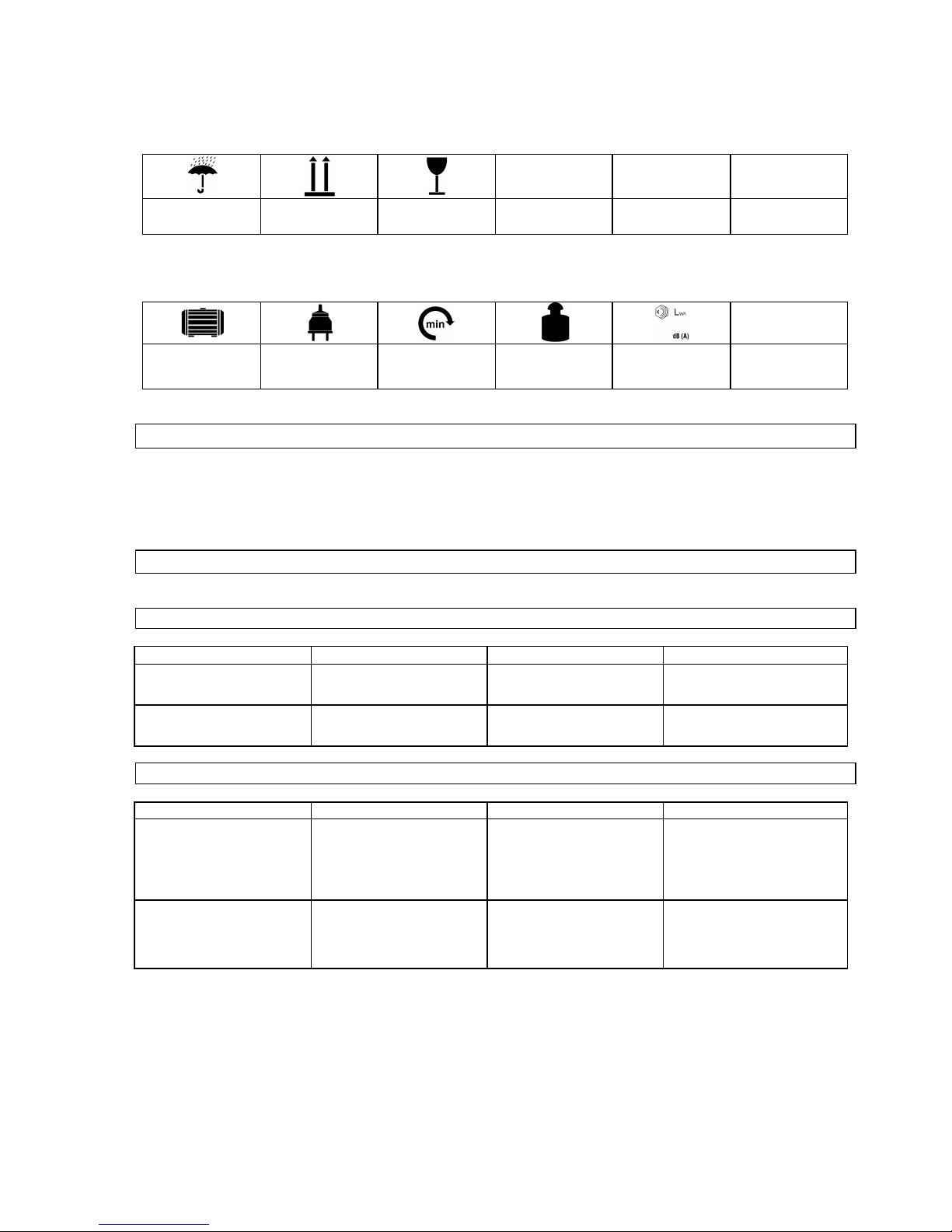
Csomagolás:
Védje nedv e ss ég ell en
A csomagolást
felállított helyzetben
tartsa
Vigyázz törékeny
Műszaki adatok:
Motor teljesítmény Dugvilla Fordulatszám/perc Súly
Az a kusz ti kus
teljesítményszint
2.3 Rendeltetés szerinti használat
A gépet kizárólag a keményfém fűrésztárcsák megmunkálására, köszörülésre/élesítésre szabad használni.
A gyártó nem felelős az általános érvényességű előírások, s a hasz nálati utasítás be nem tartás a
következtében keletkezett károkért.
2.4 Maradékveszély és óvintézkedések
2.4.1 Műszaki maradékveszély
Veszély
Megnyilvánulás
Óvintézkedés/ek
Maradékveszély
Megragadás, feltekerés
A mozgó részek elkaphatják a
lengő ruhadarabokat,
ékszereket, hosszú hajat.
Ne viseljen bő ruhát,
ékszereket. Viseljen hajvédő
hálót.
Dörzsölés , horz s olás
A forgó köszörűtárcsa
megérintése s úlyos
sebesüléseket idézhet elő.
Ne érintse meg a f orgó
fűrésztárcsát. V iseljen
védőkesztyűt.
2.4.2 Elektomos mar adékveszély
Veszély
Megnyilvánulás
Óvintézkedés/ek
Maradékveszély
Közv etlen érintkezés
villanyárammal
Hibás kábel, vagy dugvilla
áramütést okozhatnak.
.
Hibás kábelt, vagy dugvillát
cseréltesse ki szakemberrel. A
gépet kizárólag hibaáram elleni
védőkapcsolóval (FI) szabad
használni.
Nem közvetlen érintkezés
villanyárammal
Baleset áramot vezető
alkatrészekkel, nyitott,vagy
hibás konstr ukciós
alkatrészekkel.
A gépen v aló munka köz ben
mindig távolíts a el a dugvillát az
áramkörből. Kizárólag hibaáram
elleni védőkapcsolóval (FI)
szabad használni.
97
Page 90

2.4.3 Zajveszély
Veszély
Megnyilvánulás
Óvintézkedés/ek
Maradékveszély
Hallós zervek megsérülése
Hossz antartó munka a
fűrésszel a hallós zervek
károsodásához vezethet.
Munka közben mindig vis eljen
fülvédőt
2.4.4 Vesz élyeztetés munkadarabokkal és m ás anyagokk al
Veszély
Megnyilvánulás
Óvintézkedés/ek
Maradékveszély
Kontaktus,belélegzés
A nagy mennyiségű por
megkárosíthatja tüdejét.
Munka közben mindig vis eljen
respirátort.
2.4.5 Az ergonómi ai elv ek elhanyagol ása
Veszély
Megnyilvánulás
Óvintézkedés/ek
Maradékveszély
Felelőtlen hozzáállás a
személyvédő biztonsági
segédes zköz ök viselés éhez
A gép használata megfelelő
személyvédő biztonsági
segédes zköz ök nélkül s úlyos
belső és küls ő sebesülésekhez
vezethet.
Viselje mindig az előírt
munkaruhát és dolgozzon
megfontoltan.
Megfelelőtlen megvilágítás
Nem megfelelő megvilágítás
magas biztons ági kockázattal
jár.
Munka közben biz tosítson be
megfelelő megvilágítást.
2.4.6 További veszélyez tetés ek
Veszély
Megnyilvánulás
Óvintézkedés/ek
Maradékveszély
Elhajított tárgy ak, vagy
kifröccsölt folydékok.
Vágás közben a fűrésztárcsa,
vagy a m echanik us részecskék
megsérthetik a szemeit.
A géppel való m unka közben
viseljen védőszemüveget
2.4.7 Megsemmisítés
A megsem m is ítési utasítások a gépen, res p. a csom agolás on elhely ez ett pi ktogram okból ol vashatók l e. A z
egyes jel z ések magyarázata a „J elzések a gépen“ fejez etben találhat ók.
2.5 Követelmények a gép kezelőjére
A gép kezelője használat előtt figyelmesen olvassa el a használati utasítást.
2.5.1 Szakképesítés
A gép használ atához , s z akem berrel való felvi lágosít áson kívül nem sz ük séges speci áli s sz ak képesítés .
2.5.2 Minimális korhatár
A géppel kiz árólag 16 év en felüli szem él yek dolgoz hatnak.
Kivételt képez a fiatalkorúak foglal koz tatás a sz akk épz és al att az oktató felügyelet e m ellet s z akképzettség
elsajátí tása érdekében.
2.5.3 Képzés
A gép használatához elegendő szakember felvilágosítása resp. a használati utasítással való
megi sm erkedés. S peci ális képz és nem szükséges.
98
Page 91

3 Műszaki adatok
GSS 700 P
Csatlakozás:
230V/50 Hz
Frekvenció / védelemtip us:
IP 4 4
Védelmi osztály:
I
Max. teljesítmén y P 1:
370 W/P 1/S6/40%
A motor fordulats z ám a:
280 perc-1
A csiszoló korong Ø cca:
125 x 32 mm
A csiszoló korong beállítá si szö g e:
2 x 30°
A támasztó asztal beá llítá si szög e:
30° balra/80° jobbr a
Fűrésztárcsa tartójának adaptere:
35 mm, 30 mm, 28 mm, 25,4 mm, 25 mm, 18 mm, 16 mm
Csatlakozó kábel:
1,5 m/H 05 VV-F
Súly cca:
38 kg
A kusztikus teljesít m énysz in t:
73 dB (A)
Méretek H x Š z x M mm -ben:
670 x 390 x 310
Megren del ési szám :
94220
4 Szállítás és raktározás
A gép kizárólag stac ionár is haszn ála tr a van tervezve .
A gépet száraz és zárt helyiségben kell raktározni.
5 Szerelés és első üzembehelyezés
A gépet össz esz erel t állapotban forgalm az z ák , csak k i kell csomagolni .
• A szán fém alkatrészeit rendszeresen törölje meg olajos ruhával. Az orsót minden használat előtt
olajozza meg.
5.1 Biztonsági utasítások első üzembehelyezéshez
• Ügyeljen arra, hogy a gép a m egfelelő alapzatra biztonságosan fel legyen szerelve.
• Biz onyosodj on m eg arról, hogy a cs avarok be legy enek húz va.
5.2 Eljárás
• Az egyes alk atrész eket sz erelj e össz e az ábrázolt sorrendben. Ügyel jen a konstruk ciós darab ok
ábra sz erinti elrendez ésére.
99
Page 92

6 Kezelés
1.ábra
A géppel elvileg 80mm - 700 mm átmérőjű
fűrésztárcsát lehet élezni.
A fűrésztárcsát szerelje az adagoló szánra. Az
adagoló szánon 3 centír ozó nyí lás van, a különfé l e
átmérőjű fűrésztárcsákhoz ki kell választani a
megfelelő centírozó nyílást.
2.ábra
Válasszon megfelelő átmérőjű centírozó nyílást,
s közben lazítsa m eg a szorító csavar t (1b ábra ),
amivel lehetővé teszi az adagoló szán 360°-kal
való megfordítását. Kis átmérőjű fűrésztárcsa
esetén ajánlato s a (2a ábra) centír oz ó nyílás,
közepes nagy ságu esetén a m ásik két ny ílás
egyike. Kézi kerék segítségével beállítható a felső
szán is, először viszont meg kell lazítani a szorító
csavart (1c ábra). A szorító csavar m eglazítás a
után beállíthatja az átmérőt arra a fűrésztárcsára,
melyet köszörüln i akar.
3.ábra
Ha megtalálta a centíro zó nyí lás és a csiszoló
tárcsa között a megfelelő távolságot, a felső szánt
szorító csavar segí ts égével (1c ábra) rögzíts e, ez
után már ráhelyezh eti a tárcsát a centír o zó
nyílásra. Hely ezzen megfelelő adaptért a
fűrésztárcsa nyílásába. Az adaptérre helyezze rá a
nyomó tárcsát (3a ábra) és erősítse le szorító
csavarral.
Ötlet: A szorító csavart csak ann y ira szorítsa be,
hogy a fűrésztárcsát erőfeszítés nélkül meg
lehessen fordítani.
c
a b a
a
100
Page 93

4. ábra
A fogak belső felületének az élesítésére először
biztosítsa be a vágási szög megfelelő nagyságát.
A fogaknak pontosan párh uza mosn ak kell lenn iük
a csiszolótárcsa felül eté vel (lásd . a 4. ábrán és
5.ábrán a nyíl iránya)
5.ábra
Az éle sít
és az adagoló szánok előre és hátra való
mozgatásával m egy végbe, közb en vigyáz ni kell
arra, hogy az adagoló szánok úgy legy enek
beállítva, hogy kizáró lag a kemény fém felület
legy en kiéles ítve . A szánok hosszanti nyílása végütközőként szerepel (lásd. 6.ábra).
6.ábra
Ez en az ábrán világ osan láthat ó, hog y az ada goló
szánok a köszörű tárcsához képest párhuzamosan
vannak beállítva , a szánok az ütközésig haladna k,
s a csiszoló korong csak a keményfém felület ét
csiszolja. Szintén látható a kisebb fűrésztárcsára
való beállítá s.
Vigyázz: A fűrésztárcsával a szánon a legnagyobb óvatossággal haladjon, nehogy megkárosítsa a
gyém ánt tárcsát!
a
101
Page 94

7.ábra
Ütköző tűre azért van szükség, hogy a köszörű ne
kerüljön a fűrésztárcsába. Az ütköző tűt, imbusz
kulcs segítségé vel, a támasz tó csavar on kell
kalibrálni és aretálni.
8.ábra
A fűrész fogait szelektor tollal kell megjegyezni,
hogy jól lehessen látni, követni és ellenőrizni a
köszörülés alatti anyag lena gy olás át.
Ha a köszörűtárcsa szöge úgy van beállít va, hogy
a belső felület fogait egyenletesen köszörüli, a
fűrésztárcsát foganként lehet élezni.
Vigyázz:
A fűrésztárcsával térjen mindig teljesen
vissza, s
igy ekezz en , hog y ne állj on be sz agga t o tt
mozgást, ugyanis ez megkár osí thatja a csisz oló
korongot.
9.ábra
A tárcsa felső éleinek élesítéséhez a
köszörűtárcsa ferde első oldalát kell használni, a
munkaszögeket haso nló an kell beáll ít ani és
bebiztosítani, mint a fogak belső oldalán. Itt
ugyanúgy ütköző tűt kell használni, hogy be
lehessen tarta ni a fűrésztárcsa egyenletes
végleges átmérőjét.
Vigyázz:
Hogy a szerszám szánját a felső élek
élesítése után hely es irán y ba fordíthassa, az
ütköző tűt a motor oldala irányába kell fordítani
(9A ábra).
9A ábra
Ehhez az imbusz csavarn ak (9A -A ábra) lazított
állapotb an ke ll le nnie s az ütköző tű a motor
oldala irányába lesz fordít va!
a
102
Page 95

10.ábra
Váltakozó fogazat élesíté sén él a csisz oló koro ng o t
hozzá kell alkalm azni a váltako zó fogak hajlás á h o z
(m inden más odi k fogat kösz ö rü l).
11.ábra
Ez után be kell állítan i a m ár beállítot t szög et
ellenkező irányba. Így lehet megélezni az
ellenkező hajlatú fogakat.
Ötlet: Használjon szelekto r tollat.
12.ábra
Az esetben, ha kis fűrésztárcsát köszörül,
ajánlatos kicsavaro zni a támasz tó csavaro kat. Ezt
esetenként kell megállapítani a fűrésztárcsa és az
élek geomet riá ja szer int .
103
Page 96

6.1 Kezelési biztonsági utasítások
Minden karbantartás/ beállítás és javítás előtt húzza ki a dugvillát a konektorból. Ezt tegye a munka
befejez ése ut án is.
• A gépet a használati utasítás áttanul m ányoz ása után has z nálj a.
• Tartsa be az utasításban leírt biztonsági előírásokat.
• Viselkedjen felelősségteljesen más személyekkel szemben.
6.2 Utasítás lépésről lépésre
• A tartó nyílással ellátott toló szánokat a fűrésztárcsa mérete sz erint fordítsa a k ívánt hely z etbe.
• Válasszon megfelelő tartó adaptert és a tárcsát rögzítse le.
• A sz ánokat úgy állíts a be, hogy a hossz anti nyíl ásra való c sapódáskor vél etlenül ne kösz örül je a tárcsát .
• A fogak belső felületét jelezze meg fekete ceruzával, s a csisz ol ó korongot, nyugalm i áll apotban,
helyez ze arra a felületre, m el yet kös z örülni akar.
• Ez után kapcsolja be az élesítőt s a ceruzáv al m egjel ölt fel ületet a v égleges kal ibráci ó mi att dörz s ölje le.
• Ez után kösz örül jön óvatos an, egym ás után, minden fogat külön, a fűrésztárcsa mérete szerint.
• Ha a fogak belső felületét megköszörülte, a tárcsa ferde felületén egyenletesen köszörülje a fogak tetejét
ütköző segítségével, hogy be legyen biztosítva a tárcsa excentrikus futása.
• A gépet ez után alaposan ti sz títs a m eg!
•
7 Üzemzavarok - okok - eltávolításuk
VIGYÁZZ: ELLENŐRIZZE A BIZTOSÍTÉKOKAT, NEHOGY TÚLHEVÜLJENEK!
Üzemzavar
Ok
Eltávolítás
A tárcsa ég (tompa)
1. Túlságosan bekent élező felület.
2. Elk opott a gyémánt réteg.
1. Tisztítsa ki az élesítő szerszámmal
2. Cserélj e ki a tárcsát.
7.1.1 Gépszemle és karbantartás
Minden karbantartás/ beállítás és javítás előtt húzza ki a dugvillát a konektorból. Ezt tegye a munka
befejez ése ut án is.
A gépet mindig t isz t án és pormentes áll apotban tartsa.
A toló szánokat jól olajozza be, hogy megakadályozza szaggatott mozgásukat.
104
Page 97

7.2 Köszörűtárcsa csere
13.ábra
Ha cseréli a köszörűtárcsát, a motor tengelyén villás
kulcs segítségé vel ar etáln i kell a kettős élet, majd a
mot or tengelyén a biz tosító any a cs avar t vag y
meglazítani, vagy a m otor forgásir ány áb a beszorít an i
(normális jobbirány ú csavar m enet).
7.3 Gépszemle és karbantartási biztonsági utasítások
Kizárólag rendszeresen karbantar tott és kez el t gép lehet m egbízható segédesz k öz . E légtelen k arbantartás
és kezelés el
őre nem látható balesetekhez és sérülésekhez vezethet.
7.4 Gépszemle és karbantartási terv
Időközök
Tee ndők
Esetleges
további
részletek
Minden használat után
• A gépet törölje meg tiszta száraz ruhával, vagy fujja le alacsony nyomású sűrített
levegővel.
8 Pótalkatrészek
Reklam ác iót és pótalkatrész ek m egrendelését az i ll ető szervízűrlap segítségével gyorsan,
bürokráciát ki z árva int éz ünk el az alábbi cím en:
http://www.guede.com/support
Az űrlapot kikérheti:
Tel.: +49 (0) 79 04 / 700-0
Fax: +49 (0) 79 04 / 700-250
E-Mail: info@guede.com
105
Page 98

1 Naprava
Mas ivna naprava z a brušenje kol utov najv išjega razreda. Za brušenj e kolutov ž age iz trde kovine prem era
80 – 700 m m .
Poseben diamanten kolut za brušenje 125 mm, 7 nastavkov za vse običajne premere vrtanja.
Profesionalno brušenje vseh običajnih listov žage, ročnih krožnih žag, namiznih krožnih žag in žag za
ž aganje lesa z a kurjavo itd..
1.1 Obseg dobave
1. Ročno kolesce
2. Podajal ne sani
3. Tlačni kolut
4. Stiskalen vijak
5. Prislonska igla
6. Stezna ročica brusnega koluta
7. Stikalo za izklop v sili
8. Brusni k rož nik
9. Prislonski vijak
10. Stezna ročica prislonske mize
11. Stezni vijak zgornjih sani
12. Stezni vijak podajalnih sani
13. Adapterji
13
107
Page 99

1.2 Garancija
Garancija traja 12 mesecev v primeru industrijske rabe ali 24 mesecev pri potrošniku in se začne na dan
prodaje naprave.
Garancija v elja le z a tovarniške napake oz . napak e, nastale na m at erialih, iz katerih je naprava i z delana. Če
zahtevate popravila v okviru garancije vedno priložite veljaven račun, ki mora vsebovati datum prodaje in
podpis prodajal ca.
Garancija ne v elja, v kolikor napravo uporablja oseba, ki ni strokovno usposobljena, ali če do okvare pride
zaradi nestrokovnega posega v napravo ali stika s tujki oz. neupoštavanja navodil ter kot posledica običajne
uporabe.
2 Splošna varnostna navodila
Še pred uporabo naprave natančno preberi te priloženo navodilo za uporabo. Za m orebit na vprašanja gl ede
priključitve ali načina uporabe naprave, se obrnite na proizvajalca (ali na njegov servisni center).
PREDVSEM ZARADI LASTNE VARNOSTI, UPOŠTEVAJTE PROSIM SLEDEČE NAPOTKE:
POZOR!
• Naprava mora biti vedno varno, vodoravno in trdno privita na delovno mizo.
• Delov no mesto mora biti prav ilno in dovolj osvetljeno (500 luksov).
• Nikoli ne uporabljajte naprave v bližini lahko vnetljivih materialov, plinov ali tekočin.
• Uporabljajte zaščitna očala, ščitnike za sluh in primerno delovno obleko. Uporabljajte tudi dihalno napravo, če je
potrebno.
•
Vedno nosite primerno obleko. Ne nosite preširoke obleke ali nakita, ki se lahko zatakne v gibljive dele naprave.
Priporočamo Vam, da uporabljate čevlje s podplatom, ki ne drsi. Če imate dolge lase, nosite kapo ali si jih pokrijte.
• Pri delu z napravo v edno stojte trdno in v ravnotežju.
• Nepoklicane osebe in otroci naj stojijo vedno v varni razdalji od delujoče naprave.
•
Obstoječe zaščitne elemente in jih pustite na sv ojem mestu in poskrbite, da brezhibno spolnjujejo svojo funkcijo.
Delovanje brez zaščitnih elementov je strogo prepovedano.
•
Redno pregledujte, če so vsi vijaki in vijačni spoji dobro priviti.
• Prepričajte se, če se omrežni kabel ne nahaja v bližini vrtečih se delov .
• Ne puščajte naprave brez nadzora, kadar deluje. Preden napravo zapustite, jo vedno najprej izklopite.
• Pred čiščenjem oz. vzdrževanjem, pred zamenjavo nastavka ali če naprave ne uporabljate, vedno izvlecite vtič iz
vtičnice.
• Ne puščajte montažnih ključev v napravi. Pred vsakim vklopom preverite, če so montažni ključi in pripomočki za
nast avitev odstranj eni .
• Obdelovani material večjih dimenzij lahko podložite z dodatnim podstavkom.
• Roke stran od brusnih elementov napr ave.
•
• Pri delu paz ite, da z brus nim kolutom ni koli pretrdo ne uda ri t e v lis t žage! Garancije ne boste mo gl i
uveljaviti , v k olik or bo di a m ant en br u sni kolut poškodovan.
Naprava je lahko priključena le v električni mreži z FI (zaščita proti nihanju električne napetosti).
108
Page 100

2.1 Ukrepi v zasilnih primerih
Poškodovani osebi začnite čimprej dajati ustrezno prvo pomoč in pokličite zdravnika specialista v najkrajšem
možnem času.
Zavaruj te jo pred drugim i nevarnostm i i n jo pomirit e.
2.2 Oznake na napravi
L egenda sim bol o v
V tem navodilu za uporabo ali na stroju se nahajajo sledeči simboli:
Varnost izdelka:
Naprava odgovarja
standardom EU
Prepovedi:
Splošna prepoved
(skupaj z drugim
ideogramom)
Uporaba odprtega
ognja in kajenje sta
prepovedana
Dotikanje pre po v e da no
Ne vlecite za kabel
Ne dotikajte se vrtečih
se delov
Ne upor abljate izd el ka,
če dežuje
Opozorilo:
Opozorilo/previdno
Opozorilo pred
nevarnostjo
električnega udara
Upoštevajte varnostno
razdaljo
Ukazi:
Uporabljajte zaščitna
očala
Uporabljajte zaščitne
slušal ke
Uporabljajte zaščitne
rokavice.
Pred demontažo
izvl ecite vtič iz vtičnice
na zidu
Pred uporabo natančno
preberite navodilo za
uporabo
Varovanj e bivanjskeg a oko lja:
Odpadke odvrzi te
odgovorno - tak o da ne
škodujete bivanjsk emu
okolju
Kartonski ovitek j e
namenje n z a r eci klaž o,
odnes ite ga v surov ino.
Poškodovane in/ali
dotrajane električ ne
naprave oddaj te v
surovino ali na
ustrezno mesto.
Zelena točka – dvojni
s is t em Deut s c hla n d AG
109
 Loading...