

Page 1
Manual
Expert Power Control 8221 Series
Expert Power Control 8226 Series
© 2017 Gude Analog- und
Digitalsysteme GmbH
Manual Ver. 2.3.0
from Firmware Ver. 1.5
Page 2

2
Expert Power Control 8221/8226 © 2017 Gude Analog- und Digitalsysteme GmbH
Page 3

Table of contents
1. Device De scription 5
1.1 Secu r i t y Ad v ic e .............................................................................................................. 6
1.2 Conten t of Deliv er y ........................................................................................................ 6
1.3 Description ..................................................................................................................... 6
1.4 Installation ...................................................................................................................... 7
1.5 Dual-Circuit Char a c t er ist ic s ........................................................................................... 8
1.6 Overvolt a g e Pro t ec tion ................................................................................................. 9
1.7 Techn i c al S pecification s .............................................................................................. 10
1.7.1 Electrical Measuremen t ......................................................................................... 10
1.8 Sensor ........................................................................................................................... 11
2. Operating 13
2.1 Opera t i n g t he dev ic e directly ..................................................................................... 14
2.2 Contr ol Panel ................................................................................................................ 14
2.3 Maintenance ................................................................................................................ 16
2.3.1 Mainten ance Page ................................................................................................. 18
2.3.2 Configuration Management ................................................................................... 19
2.3.3 Boot loader Activation ............................................................................................. 20
3. Configuration 22
3.1 Pow er Ports .................................................................................................................. 23
3.1.1 Watchdog ............................................................................................................... 24
3.2 Ethernet ........................................................................................................................ 26
3.2.1 IP Addr ess ............................................................................................................... 26
3.2.2 IP ACL ..................................................................................................................... 28
3.2.3 HTTP ....................................................................................................................... 29
3.3 Protocols ....................................................................................................................... 30
3.3.1 Console ................................................................................................................... 30
3.3.2 Syslog ..................................................................................................................... 31
3.3.3 SNMP ...................................................................................................................... 32
3.3.4 Radius ..................................................................................................................... 33
3.3.5 Mo dbu s TCP ........................................................................................................... 34
3.4 Sensors .......................................................................................................................... 35
3.4.1 Por t Switch ing ......................................................................................................... 36
3.5 E-Mail ............................................................................................................................ 38
3.6 Front Panel ................................................................................................................... 39
4. Specifications 40
4.1 IP ACL ............................................................................................................................ 41
4.2 IPv6 ................................................................................................................................ 41
3
Expert Power Control 8221/8226 © 2017 Gude Analog- und Digitalsysteme GmbH
Page 4

Table of contents
4.3 Radius ............................................................................................................................ 42
4.4 Aut omated A ccess ....................................................................................................... 42
4.5 SNMP ............................................................................................................................ 43
4.5.1 Device MIB 8221 .................................................................................................... 45
4.5.2 Device MIB 8226 .................................................................................................... 47
4.6 SSL ................................................................................................................................. 50
4.7 Console .......................................................................................................................... 52
4.7.1 Console Cmd 8221 ................................................................................................. 54
4.7.2 Console Cmd 8226 ................................................................................................. 61
4.7.3 Ser ial Console ......................................................................................................... 68
4.8 Modbus TCP .................................................................................................................. 69
4.9 Messages ....................................................................................................................... 73
5. Support 7 4
5.1 Data S ec urit y ................................................................................................................ 75
5.2 Contact .......................................................................................................................... 75
5.3 Declaration o f Con fo r mity .......................................................................................... 76
5.4 FAQ ................................................................................................................................ 77
Index
78
4
Expert Power Control 8221/8226 © 2017 Gude Analog- und Digitalsysteme GmbH
Page 5

Device Description
Page 6

Device Description
1 Device De scription
1.1 Security Advice
·
The device mus t be installed only by qualified personnel according to the following installation and operating instructions.
·
The manufac turer does not acc ept responsibilit y in cas e of improper use of the devic e
and particularly any us e of equipment that m ay cause personal injury or material damage.
·
The device c ontains no user-maintenable parts. A ll maint enance has to be performed
by factory trained servic e personnel.
·
This devi c e contains potentially hazardous volt ages and should not be opened or disassembled.
·
The device c an be connected only to 230V AC (50 Hz or 60 Hz) power supply s oc kets.
·
The power cords, plugs and sock et s have to be in good condition. Always connect the
device t o properly grounded power sock et s .
·
The device is intended for indoor use only. Do NOT install t hem in an area where excessive moisture or heat is present.
·
Because of safety and approval issues it i s not allowed to modify the device without
our permiss ion.
·
The device is NOT a toy . It has to be used or st ored out or range of children.
·
Care about packaging material. Plasti c s has t o be st ored out of range of children.
Please recycle the packaging materials.
·
In case of further questions, about inst allat ion, operation or usage of the device, which
are not c lear after reading the manual, please do not hesitate to ask our support team.
·
Please, never leave connected equipment unattended, that can cause damage.
·
Connect only elect rical devic es t hat do not have limited on-time. I.e. i n c as e of failure,
all connected appliances have to cope with a continuous on-time without causing
damage.
1.2 Content of Delivery
The package includes:
·
Expe rt Power Control 8221-1/8226-1
·
2 x Power Supply cable (IEC C19, max. 16 A)
·
CD-ROM with Manual and Softwaretools
1.3 Description
The Expe rt Power Control 8221-1/8226-1 can switch 12 different load outputs (IEC
C13, max. 10A), which each 6 outputs are fed from a mains connection (IEC C20, max.
16A) . The device has t he following features:
·
Switc hing of 12 load outputs.
6
Expert Power Control 8221/8226 © 2017 Gude Analog- und Digitalsysteme GmbH
Page 7

Device Description
·
Energy Metering of the two mains connections and measurement of volt age, c urrent,
active power, reactive power, apparent power, frequency, phase angle, power fact or.
·
Continuously and resettable energy m eters on the mains c onnecti ons.
·
Energy Metering and meters for each port of the 12 load outputs and measurement of
voltage, c urrent, act i ve power, reactive power, apparent power, frequency , phase
angle, power factor per output (8226-1 only).
·
Connecting of two optional ext ernal sensors to determine the temperature and humidity , or a input switc h.
·
Two four-digit 7-segment LED displays (for display of current or temperature / humidity
of the ext ernal sensors).
·
Separated over-voltage protection of the two mains connections (Overvolt age Protection).
·
Startup delay, individually parametrizable for all load outputs.
·
Indivi dually adjust able watchdog function that s wit c hes power ports in dependency of
the acces sibility of a device (network ping).
·
Dual TCP/IP S t ac k with IPv4 and IPv6 support.
·
Control and monitoring of the device vi a Ethernet with an integrated web server and
SNMP (v1, v2c and v3).
·
Console Commands with telnet s upport and serial interface.
·
Generation of messages (E-Mail, Syslog and SNMP traps) and relay switching depending on the energy measurement limits, resp. ex t ernal sensors.
·
Secure E-Mails.
1.4 Installation
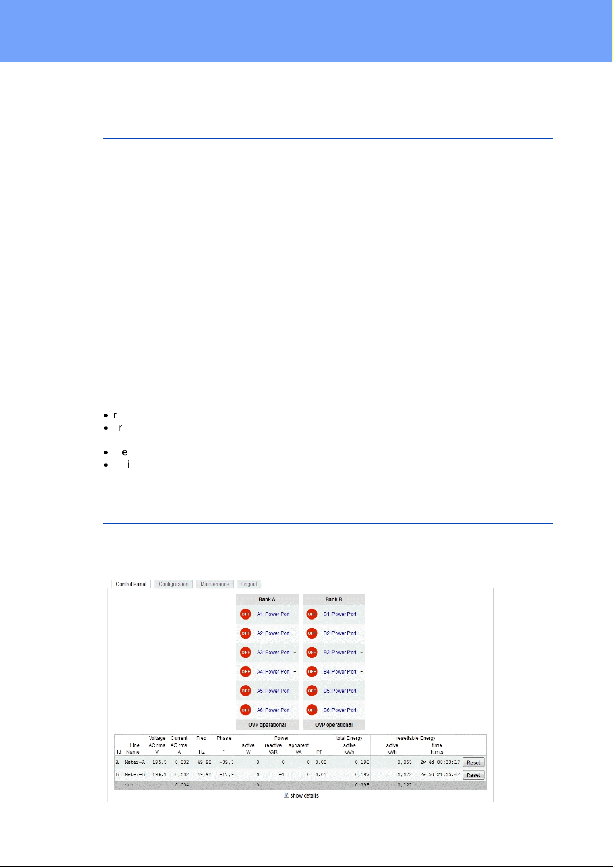
1. 6 plain text dis plays (on/off) for the state of the outputs (Bank A or B)
2. Current power consumption of the Bank
3. LED indicator whether the Bank is c onnected to m ains supply
4. LED indicator for Over Voltage Protect ion (green - surge protecti on is ac t i ve, red - inactive)
7
Expert Power Control 8221/8226 © 2017 Gude Analog- und Digitalsysteme GmbH
Page 8
Device Description
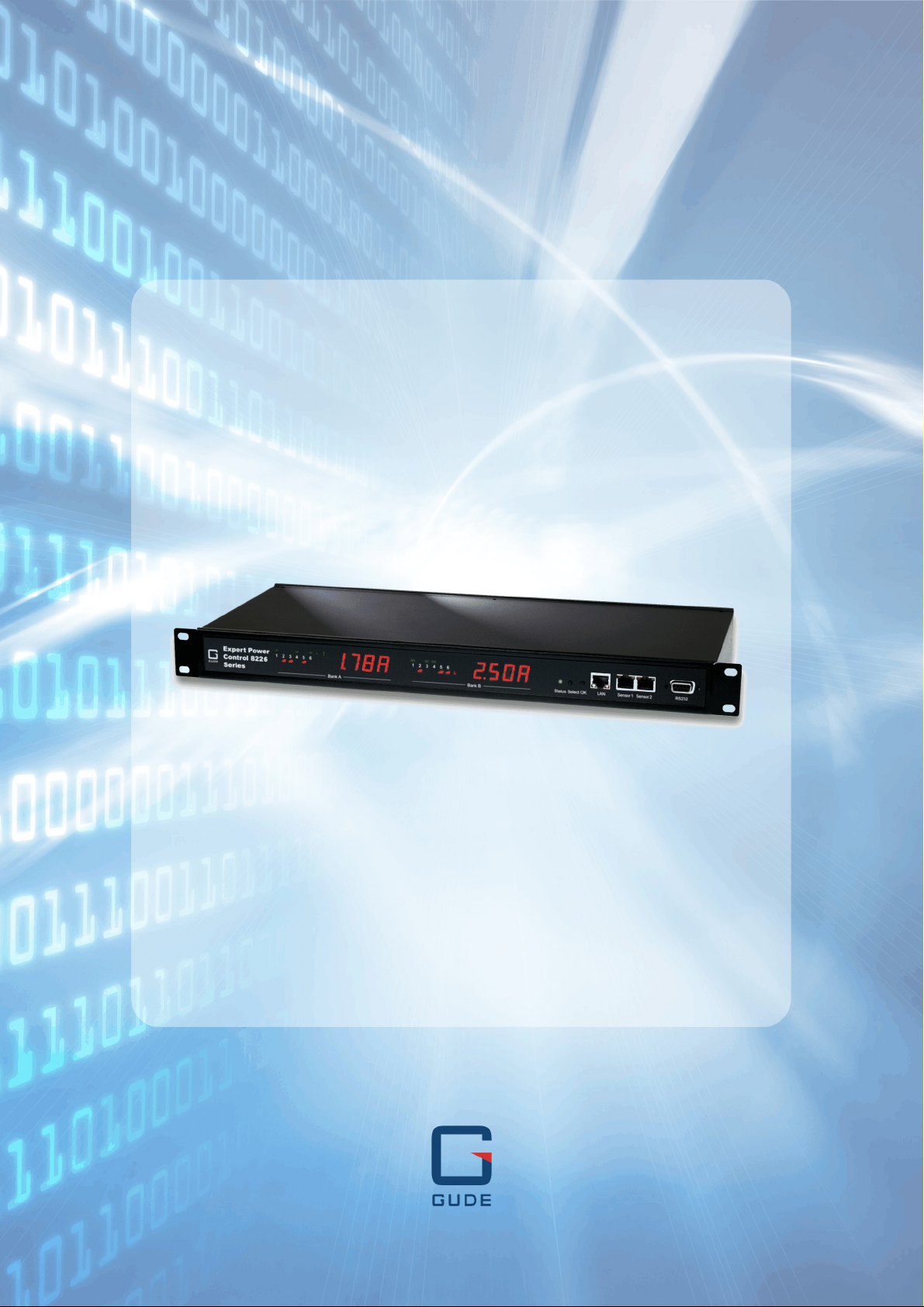
5. St atus LED
6. Select butt on
7. Ok butt on
8. Et hernet connector (RJ45)
9. Ex t ernal sensor connectors (RJ45)
10. RS232 connector
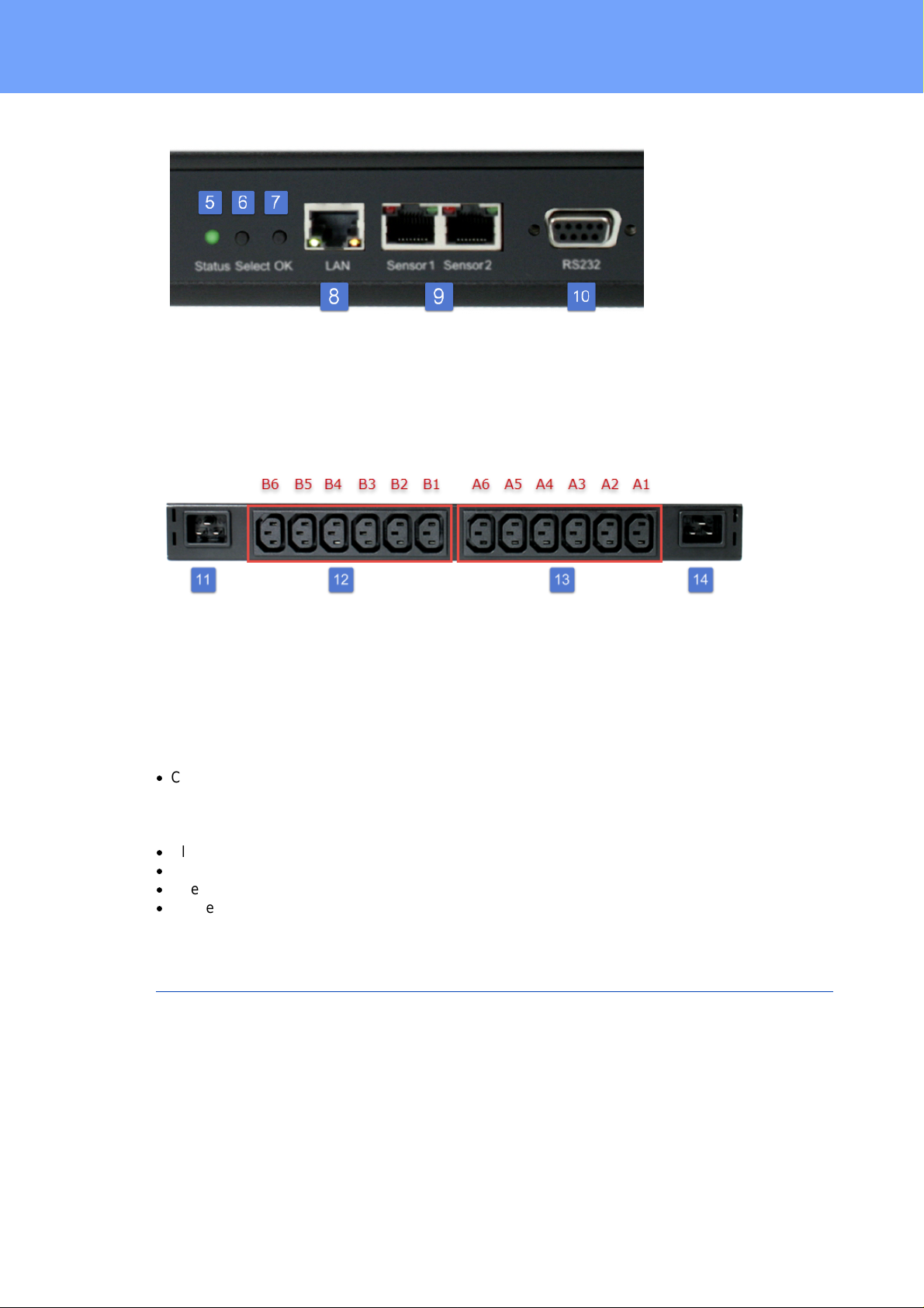
11.M ains supply Bank B (IEC C20, max . 16A)
12.6 x Load outputs B ank B (IEC C13, max. 16A)
13.6 x Load outputs B ank A (IEC C13, max. 16A)
14.M ains supply Bank A (IEC C20, max . 16A)
Start-up the device
·
Connect the two power cords (IEC C19, max. 16A) to t he mains s upply. The cable
connectors are secured as regards their ty pe against unintentional loosening. They
must be inserted up to the st op, otherwise there is no secure connection. The plug
must not wobble in the socket , or there is no tight c onnection.
·
Plug the network cable into the Ethernet sock et (RJ45).
·
If required, s et up a serial connection to t he RS232 port.
·
Insert t he optional external sensors into t he sens or connectors.
·
Connect the consumers with the load outputs (IEC C13, max. 10A).
1.5 Dual-Circuit Characteristics
The Expert Power Control 8221-1/8226-1 has two different input circ uit s (Banks A and
B). Therefore the mains supply A ( IEC C20, max . 16 A ) feeds the current t o t he load
outputs A1 t o A 6 (IEC C13, max. 10 A), resp. mains supply B feeds the current t o t he
load outputs B 1 t o B 6 (IEC C13, max . 10 A ) . The elect ronics of the device works when
one of t he t wo input circuit s is supplied .
8
Expert Power Control 8221/8226 © 2017 Gude Analog- und Digitalsysteme GmbH
Page 9
Device Description
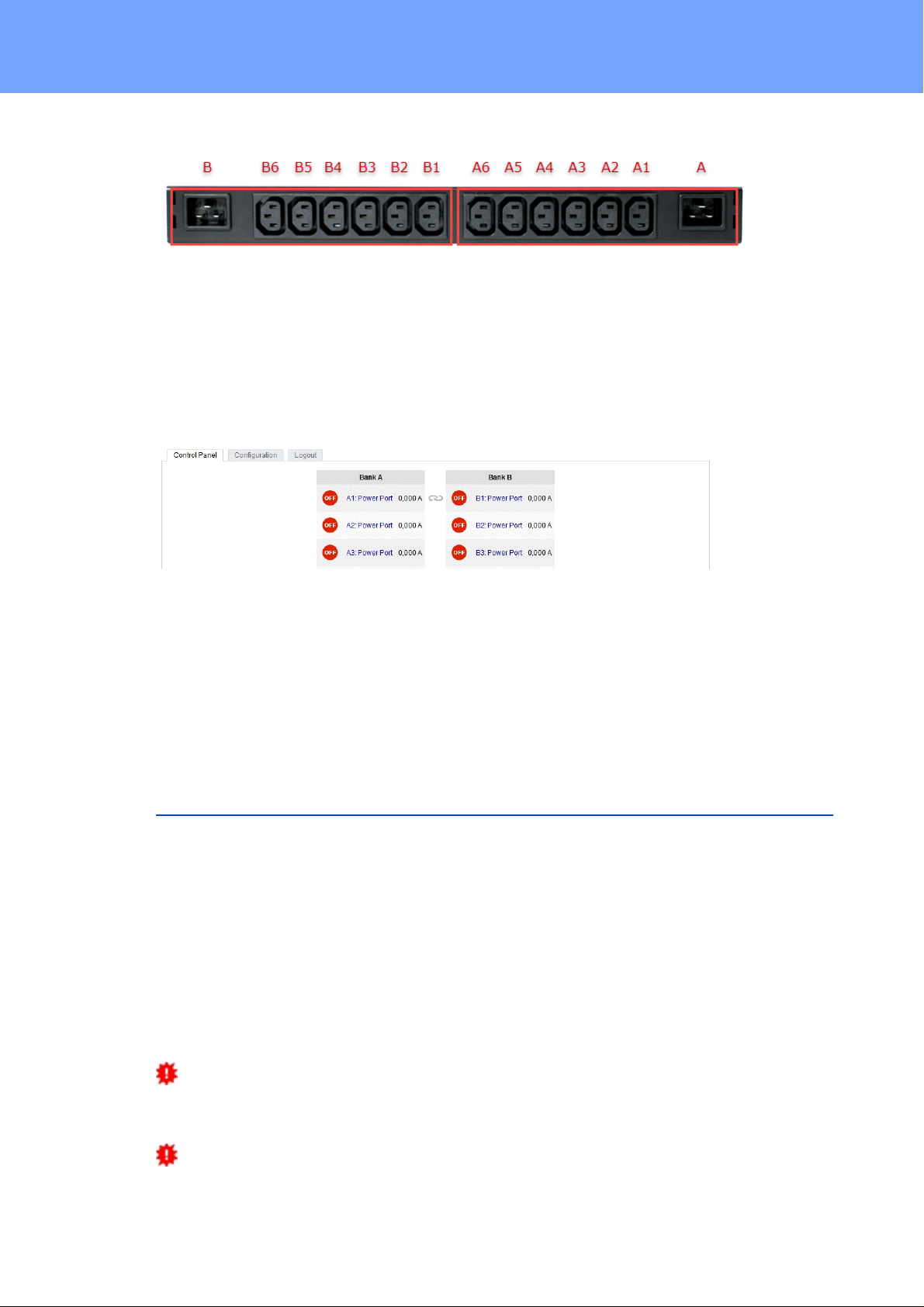
Twin Port
Two ports of different Banks but with t he same number can be combined to a "twin port".
Then one port always participates i n t he swit c hing status of the other port. In the sc reenshot t he ports A1 and B1 are combined, symboliz ed by the chain link ic on. The "Connect t win port" option can be found in the chapter "Configuration - Power Ports" .
Currentless Bank
If a bank is not receiving enough power smaller 70 V), a red "L" appears in the front
panel display , while a operating power supply s hows a green " L". Upon entry of the current loss all relays are switc hed off by t he elect ronics , but t he "On" and "Off" LEDs still
show the state of the relays when the supply was active. This is s ymbolized by t he
flashing of the LEDs.
1.6 Overvoltage Protection
The device c ontains an overvoltage protect i on at each of the banks. The protection is
based on input s ide varistors with thermal fuse between phase (L) and neutral (N) to protect the internal elect ronics and power ports with failure detection (permanently triggered
thermal fuse). The state of the protecti on is indic ated on the front panel by a green or red
flash. A green fl as h means t hat t he protection is ac tive, a red flash symboliz es that the
overvoltage protection fails. In addition, the status of the overvoltage protection can be
seen on the Webpage (HTTP) and acquired with SNMP. Eac h surge protection module
is designed that it can derive a pract ical unlimited number of voltage pulses in normal installat ion environments. In an environment with many energy rich surge pulses it can
result in permanent loss of function due to aging of the overvoltage protection element.
Recovering of t he overvolt age protection function can only be performed by the manufacturer of the device. In the normal cas e, t he device will continue to work even after the
failure of the protective funct i on.
A s ignaling via E -Mail, S yslog or SNMP trap occ urs only once during operation, exactly at t he moment in which the protection fails. In addition, at the st art up of the device
a message is generated, when the overvoltage protection is not ac t ive.
9
Expert Power Control 8221/8226 © 2017 Gude Analog- und Digitalsysteme GmbH
Page 10

Device Description
Interfaces
1 x Ethernet port (RJ45)
1 x Serial connector (D-SUB, RS232)
2 x Mains s upply (IEC C20, m ax.16 A)
2 x 6 Load outputs (IEC C13, m ax. 16
A)
2 x RJ45 for ext ernal sensor
Network c onnectivity
10/100 MBit/s 10baseT E thernet
Protocols
TCP/IP, HTTP / HTTPS, S NMP v1/v2c/ v3,
SNMP t raps, S ysl og, E -Mail (SMTP)
Power Supply
internal power supply (90-265V AC / -
15% / + 10%)
Overvoltage Protect ion
·
single peak current for 20/80us puls e
·
max. c l amping volt age 20/80us pulse,
Ipk = 100 A
20 mm / 250 J varistor disk (300V AC)
10000 A
775 V
Environment
·
Operating temperature
·
Storage temperature
·
Humidity
0°C - 50 °C
-20°C - 70 °C
0% - 95% (non-condensing)
Case
powder coated, galvanized st eel s heet
Measurements
19" (inches), 1 Rack Unit, (Depth 195
mm)
Weight
approx. 2.9 k g (8221-1)
approx. 3.0 k g (8226-1)
1.7 Technical Spec if ications
1.7.1
Expert Power Control 8221/8226 © 2017 Gude Analog- und Digitalsysteme GmbH
Elect r ic a l Measur ement
typical fault tolerances for Ta=25°C, I=1Arms...16Arms, Un=90Vrms...265Vrms
10
Page 11
Device Description
Electrical Me asurement Spe ci fication
Category
Range
Unit
Resolution
Inaccuracy
(typical)
Voltage
90-265
V
0.01
< 1%
Current
0 - 16
A
0.001
< 1.5%
Frequency
45-65
Hz
0.01
< 0.03%
Phase
-180 - +180
°
0.1
< 1%
Active power
0 - 4000
W1< 1.5%
Reactive power
0 - 4000
Var1< 1.5%
Apparent power
0 - 4000
VA1< 1.5%
Power factor
0 - 1-0.01
< 3%
Energy Counter
Active E nergy
(total)
9.999.999,999
kWh
0.001
< 1.5%
Active E nergy
(temporary)
9.999.999,999
kWh
0.001
< 1.5%
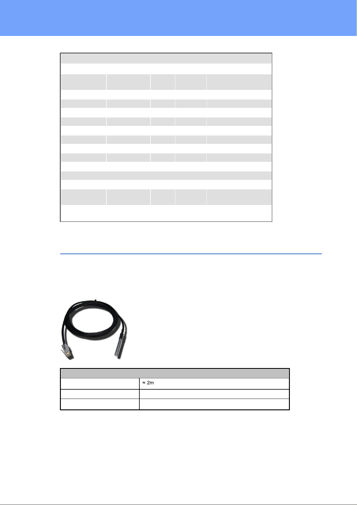
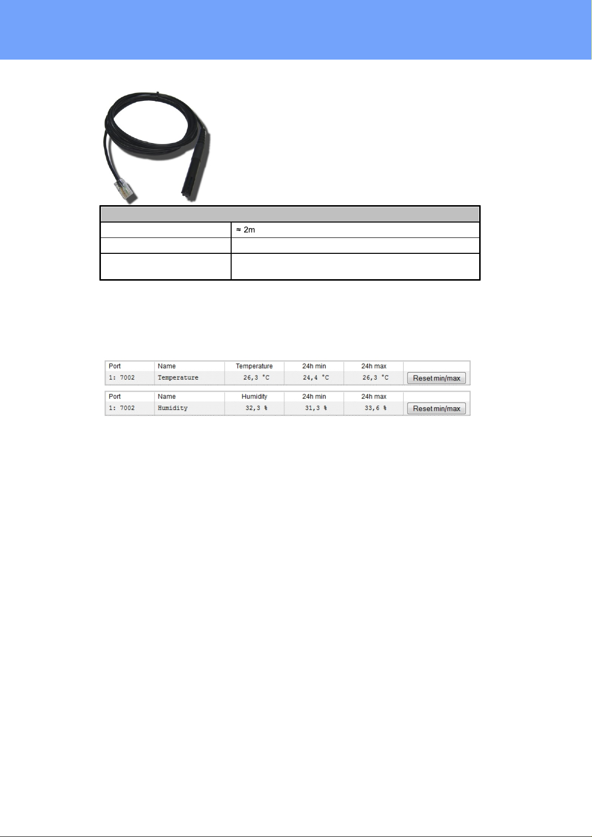
Temperature-Sensor 7101
Cable length
Connector
RJ45
Measureme nt range
-20°C to +80°C at ±2°C (maximu m) and ±1°C (typical)
1.8 Sensor
T wo external sensors can be connected to the Expe rt Power Control 8221-1/8226-1.
The following sensors are currently available
11
Expert Power Control 8221/8226 © 2017 Gude Analog- und Digitalsysteme GmbH
Page 12
Device Description
Humidity/Temperature-Sensor 7102
Cable length
Connector
RJ45
Measureme nt range
Temp: -20 to +80°C, ±0,5°C (maximum) and ±0,3°C (typical)
Humidi t y: 0-100%, ±3% (maximum) and ±2% (typical)
The sensors are automatically detec t ed after connect . This is indic ated by t he green
LED on the sensor port that is lit permanently. Th e sen sor v al u es are displayed at the
"Control Panel" web page:
Expert Power Control 8221/8226 © 2017 Gude Analog- und Digitalsysteme GmbH
12
Page 13

Operating
Page 14
Operating
2 Operating
2.1 Operating the de vice directly
Port Switching
The current s tatus of the output is indic ated by t he c olor of the LED. Red indicates that
the output is off, green shows that the output is on. On t he devic e are the buttons "select" and "ok" . If you press " select" , the LED will blink for the first output, i e the output is
select ed. P ress "select" again to select the next output. Hold down the button "ok" for
two seconds, t hen the st at us of the select ed output is t oggled.
Display Informat i on
If no port is selected manually, repeatedly pressing the "ok" button will show the IP-address and the values of the external sensors on the display.
Status-LED
The Status LE D shows t he different states of the device:
·
red: The device is not connected to the Ethernet.
·
orange: The device is connected to t he Et hernet and waits for data from the DHCP
server.
·
green: The devic e is connected to t he Et hernet and the TCP/ IP s ettings are allocated.
·
periodic blink ing: The devi ce is in B ootloader mode.
2.2 Control Pane l
Access the web interface: http:// " IP-address " and log-in.
14
Expert Power Control 8221/8226 © 2017 Gude Analog- und Digitalsysteme GmbH
Page 15
Operating
The web page provides an overview of the switching st at e, energy measurement values of
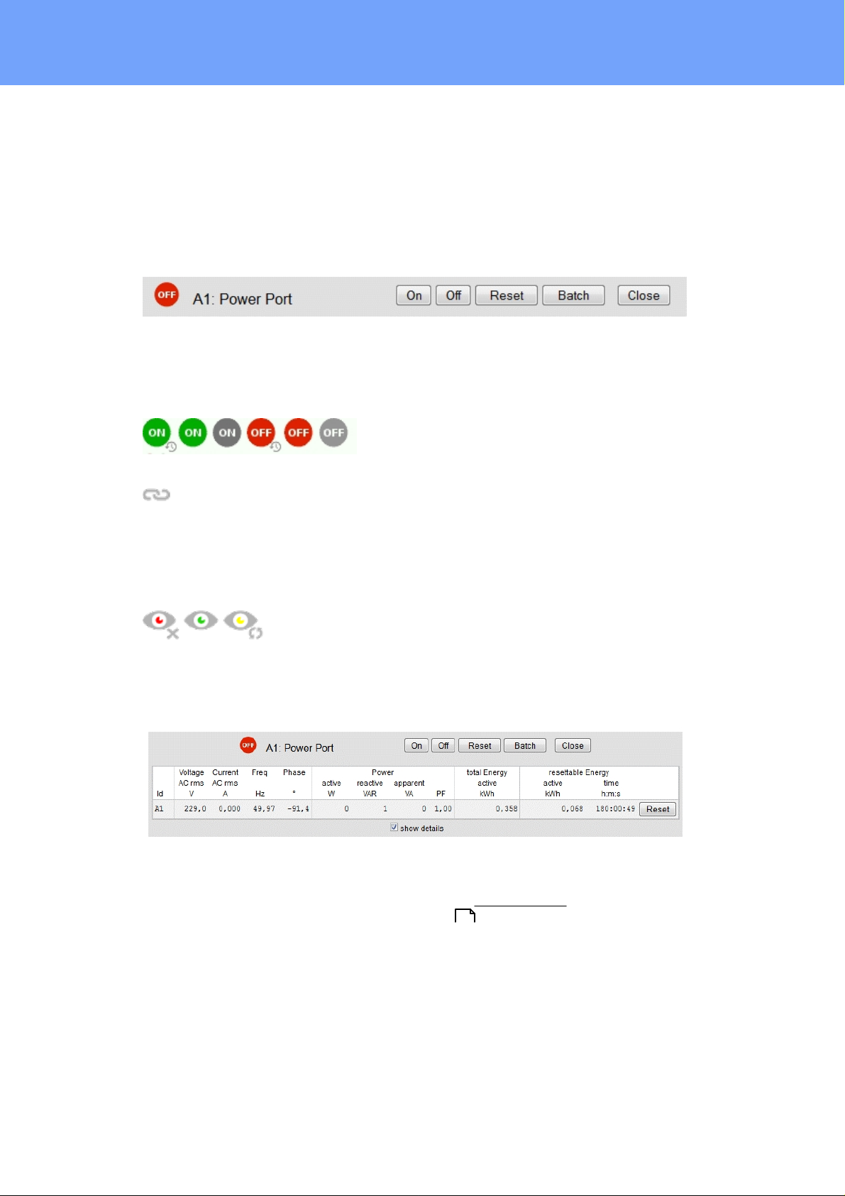
the banks "A " and "B", as well as the external sensors, provided that they are connected. When a single port is clicked at the Expe rt Po wer Control 8221-1/8226-1, a panel
with buttons to control a single port appear:
The Port icon is green when the relay is c los ed, or red in the open st ate. If a bank has
no voltage, the state is represented by a gray P ort icon. An additional small clock i c on
indicates that a timer is active. Timer can be activated by delay, reset or batch mode.
Two outputs configured as twin ports are connected by a chain icon.
An acti vated Wat chdog is represented by an eye icon. A n " X" means, that the address
that s hould be observed, could not be resolved. Two circular arrows show a booting
status.
In add ition to the panel, the Expert Power Control 8226-1 shows the measured values
of the selected port:
The ports c an be switched manually wit h the "On" and "Off" buttons. If the port is t urned
on, it c an be turned off by pressing the "Reset " butt on, unti l after a delay it turns it self on
again. T he delay time is determined by the parameter Reset Duration, which is desc ribed in the chapter "Configuration - Power Ports ". The "Close" button diss olves
the panel again.
23
Batchmode
Each indivi dual port can be set for a selectable period of tim e t o t he st at e " switch on" or
"swit ch off" . A fter the select ed ti me t hey are automatically switched to t he sec ond
preselected stat e.
15
Expert Power Control 8221/8226 © 2017 Gude Analog- und Digitalsysteme GmbH
Page 16

Operating
Optionally the devic e c an be switched via a Perl sc ript or ext ernal tools like wget. More
info rmation is available on our support wiki at www.gude.info/wiki.
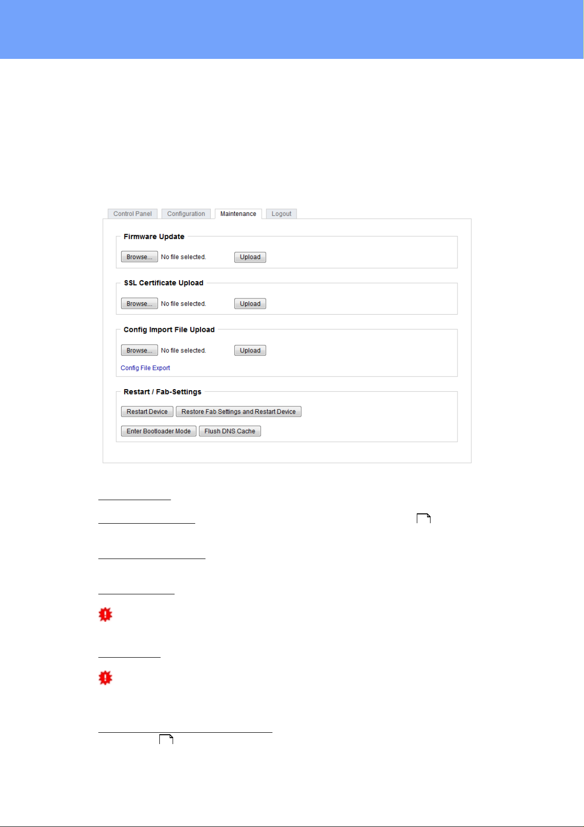
2.3 Maintenance
The actual devic e generation with IPv6 and SSL allows all maintenance functions in the
web interface to be carried out on the Maintenance Page .
Maintenance in the web interface
The following functions are available from the maintenance web page:
18
·
Firmware Update
·
Change the SSL certificate
·
Load and save the c onfiguration
·
Restart the devic e
·
Factory Reset
·
Jump into the Bootloader
·
Delete the DNS cac he
Upload Firmware, Certificate or Configuration
On the Maintenance Page , s elec t t he required file with " B rowse .." in the sec t i ons
"Firmware Update", "S SL Certificate Upload" or "Config Import File Upload" and press
"Upload". The file is now transferred to the update area of the devic e and the contents
are checked. Only now, pressing the "A pply " button will permanently update the data, or
abort with " Cancel".
Only one upload funct ion c an be initiated with a reboot, eg. you cannot transmit firm-
ware and configuration at t he s ame ti me.
If after a firmware update, the web page is not displayed c orrectly any more, this may
be related to the interacti on of Javascript with an outdated browser cache. If a Ctrl-F5
does not help, it is recomm ended that you manually delete the cache in the browser options. A l t ernatively , you c an tes t start t he browser in "privat e mode".
18
Acti ons i n Bootloader mode
If t he web interfac e of the device is no longer acces sible, the device can be put into
Bootloader mode (see chapter Bootloader activat ion ). The following functions can be
executed using the GBL_Conf.exe application:
·
Set IPv4 address, net-mask and gateway
·
Turn HTTP password on and off
·
Turn IP-ACL on and off
20
16
Expert Power Control 8221/8226 © 2017 Gude Analog- und Digitalsysteme GmbH
Page 17
Operating
Interface GBL_Conf
·
Factory Reset
·
Jump into the bootloader (can be switc hed on and off)
·
Restart the devic e
For devices with relays , entering or exiting the bootloader mode does not c hange
the st ate of the relays as long as t he operating voltage is maintained.
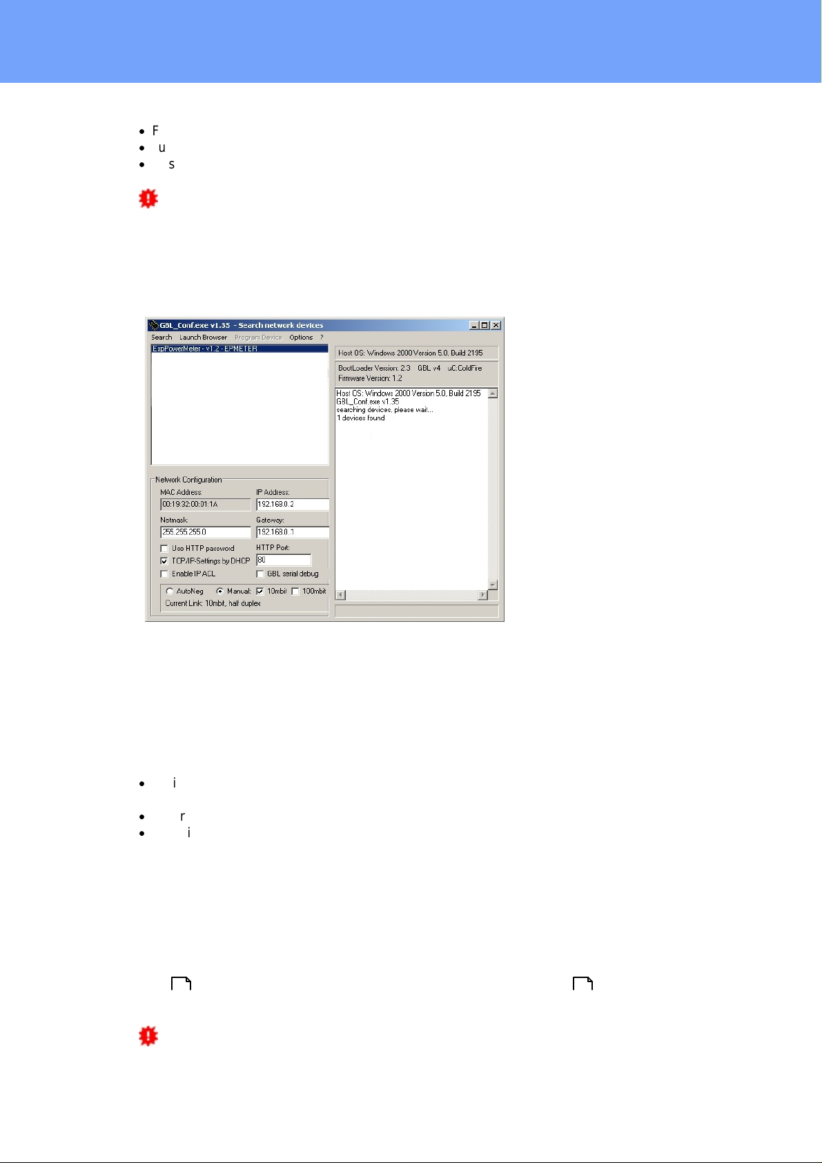
The GBL_Conf.exe program is available free of charge on our website www.gude.info and
can also be found on the enclos ed CD-ROM.
To check the network settings with GBL_Conf.exe, start the program and choose "All
Devices" in the "Search" menu. From the list s elec t the appropriate device. The lower
part of the left half of the window now shows the current network s ettings of the device. If
the IP address i s dis play ed with the default s et t ings (192.168.0.2), either no DHCP
server is present on the network, or there could be no free IP address ass i gned to it.
·
Activate the Bootloader Mode (see Chapter Bootloader Mode) and choose in menu
"Search" t he it em " B ootloader-Mode Devices only"
·
Enter the desired settings in the edit window and save them with "Save Config".
·
Deactivat e the boot loader mode for the changes to take effect. Select again "All
Devices" in the "Search" menu of GBL_Conf .exe.
The new network configuration is now displayed.
Factory Reset
The device can be reset to the factory default via t he web interface from the Maintenance
18 20
Page or fr om the Bootloader mode (see chapter Bootloader activat ion ). A ll TCP/IP
sett ings are reset in this operation.
If a unit is s et to factory defaults, an uploaded certificat e or updated firmware will be
preserved.
17
Expert Power Control 8221/8226 © 2017 Gude Analog- und Digitalsysteme GmbH
Page 18
Operating
2.3.1
Maint en a n c e Page
This section provides access to important functi ons such as Fi rmware Update or Restart
Device. It is advis able to s et an HTTP password for this reason.
Firmware Update: S tart a firmware update.
SSL Certificate Upload: S aves y our own SS L c ertificate. S ee c hapter "SSL " for the
generation of a certificate in t he right format.
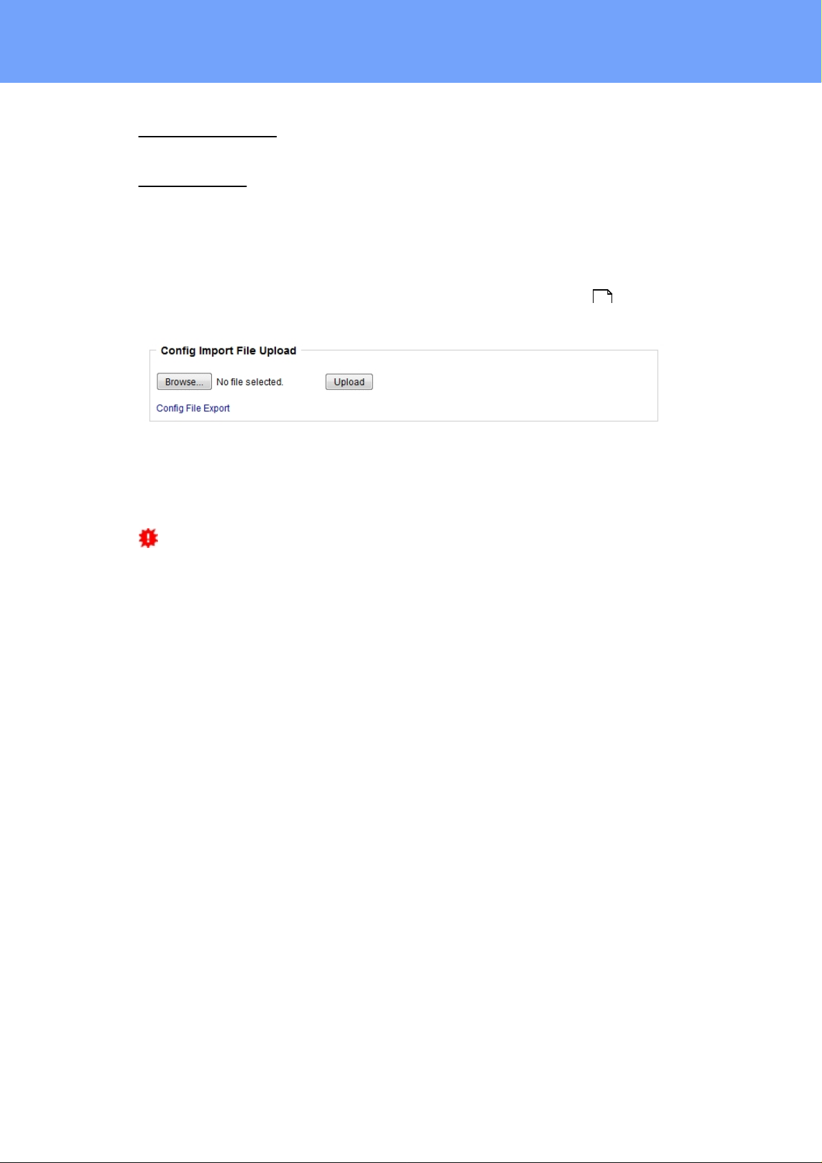
Config Import File Upload: Loads a new confi guration from a text file. To apply t he new
configuration, a "Restart Device" must be executed after the "Upload".
Config Fil e Export: Saves the c urrent configuration in a text file.
Saving the configuration should only be c arried out in an SS L c onnection, since it
contains sensitive password information (even if it is encrypted or hashed).
Restart Device: Rest arts the device without changing the status of the relays.
Some functions s uch as a firmware update or changing of the IP-address and HTTP
sett ings require a restart of the device. A j ump to t he boot loader or a restart of the
device lead by no means to a change of the relay st at es .
Restore Fab Settings and Restart Device: Performs a restart and resets t he devic e t o
factory default .
21
51
18
Expert Power Control 8221/8226 © 2017 Gude Analog- und Digitalsysteme GmbH
Page 19
Operating
Enter Bootloader Mode: Jumps into bootloader mode, where additional settings can be
made with GBL_Conf.exe.
Flush DNS Cache: All entries in t he DNS cache are discarded and address resolutions
are requested again.
2.3.2
Configu ratio n Management
The device configuration can be saved and restored in the maintenance area .
The "Confi g File E xport" function can be used to save t he current configuration as a text
file. The syntax us ed in the configuration file corresponds to t he comm ands of the Telnet
console. If the configuration of a devi c e is to be restored from a text file, load the file with
"Upload" and restart the device with "Restart Device".
Saving the configuration should only be c arried out in an SS L c onnection, since it
contains sensitive password information (even if it is encrypted or hashed). For the same
reasons, it i s advi s able to c arefully handle the generated configuration files when archiving.
18
Editing the configurati on fi le
It is poss i ble to c us tomize a s aved configuration file with a text edit or for your own
needs. For example, one sc enario would be to use a script language to automate t he
creation of many c us t omi z ed versions of a configuration, then equip a large number of
devices wit h an individualized configuration. A lso Upload and rest art with CGI commands
can be done in sc ripting languages. Wit h use of the comment s i gn "#" y ou c an quick ly
hide single commands or add personal notes .
If you modify a c onfiguration file manually, it is not always c l ear which limits are allowed
for parameters. A fter uploading and restarting, commands with invalid parameters are ignored. Therefore, the generated configuration includes comments describing the boundaries of the parameters. Where "range:" refers to a numeric value, and "len:" t o a t ex t
parameter. E. g:
email a u th set 0 #rang e: 0..2
email u s er set "" #len : 0..10 0
The command "syst em fabsetti ngs" from the beginning of a generated configuration file
brings the device into t he factory state, and then executes the individual commands that
modify the configuration state. It may be desirable to make the changes relative t o t he
current configuration, and not out of the fact ory state. Then the "s yst em fabsettings"
should be removed.
Confi gurati on via Telnet
19
Expert Power Control 8221/8226 © 2017 Gude Analog- und Digitalsysteme GmbH
Page 20

Operating
The configuration files can in principle also be transferred in a Telnet session, but then
the sett i ngs are changed during operation, and not c ompletely when restarting, as it
would have been the case with an upload. It can happen that events are triggered at the
same tim e as t he devic e is configured. One should therefore:
a) dis able the function
b) c ompletely parametrize
c) reactivate the funct i on
An example:
email e n abled s et 0
email s e nder se t "" #len: 0.. 100
email r e cipien t s e t "" #len: 0.. 100
email s e rver se t "" #len: 0.. 100
email p o rt set 25
email s e curity set 0 #range: 0..2
email a u th set 0 #rang e: 0..2
email u s er set "" #len : 0..10 0
email p a sswd ha sh set "" #len : 0..10 0
email e n abled s et 1 #range: 0 ..1
2.3.3
Bootload er A c t ivation
The configuration of the device from the application "GBL_Conf. ex e" is only poss i ble, if
the device is in Bootloader Mode.
Acti vat i on of t he Bootloader Mode
1) via push button:
·
Hold both buttons for 3 seconds
2) or
·
Remove the power supply
·
Hold down the "Select" button. If the push button is recessed, use a pin or paper clip
·
Connect the operating voltage
3) by Software: (only if "Enable FW t o B L" was previously acti vated in the
"GBL_Conf.exe" applicati on)
·
Start t he "GB L_Conf.exe" program
·
Do a network search with the "Search" menu acti on
·
Activ a te in menu "Program Device" the item "Enter Bootloader"
4) via web interface:
Press "Enter Bootloader Mode" on the maintenance web page.
Whether the device is in Bootloader mode, is indicated by t he flashing of the st atus
LED, or it is shown in "GB L_Conf.exe" applicati on after a renewed device s earch (ap-
18
20
Expert Power Control 8221/8226 © 2017 Gude Analog- und Digitalsysteme GmbH
Page 21

Operating
pendix " B OOT-LDR" after the devic e name). In Bootloader mode the program
"GBL_Conf.exe" c an disable the pass word and the IP ACL, perform a firmware update,
and rest ore the fact ory s et t i ngs.
For devices wit h relays, entering or exiti ng the bootloader mode does not change the
stat e of the relays as long as t he operating voltage is maintained.
Abandonment of the Bootl oader Mode
1) via push button:
·
Hold both buttons for 3 seconds (only if the device has 2 buttons)
2) or
·
Remove and connect t he power supply without operating a butt on
3) by Software:
·
Start t he "GB L_Conf.exe" applicat ion
·
Do a network sear ch with the "Search" m enu action
·
In menu "Program Devic e" activa te the item "E nter Firmware"
Factory Reset
If t he device is in bootloader mode, it can always be put back t o it s factory default. A ll
TCP/IP set t i ngs are reset in this operation.
If a unit is s et to factory defaults, an uploaded certificat e or updated firmware will be
preserved.
1) via push button:
·
Activat e t he Bootloader Mode of the devi ce
·
Hold down the button (or the "Select" button for devices with 2 buttons) for 6 seconds.
If t he push button is reces s ed, us e a pin or paper clip
·
The stat us LED will blink in a fast rhyt hm, please wait until the LED blinks s lowly
(about 5 sec onds)
2) by Software:
·
Activat e t he Bootloader Mode of the devi ce
·
"St art t he GBL_Conf.exe" program
·
In menu " P rogram Device" ac t ivate the item "Reset to Fab Set t ings"
·
The stat us LED will blink in a fast rhyt hm, please wait until the LED blinks s lowly
(about 5 sec onds)
21
Expert Power Control 8221/8226 © 2017 Gude Analog- und Digitalsysteme GmbH
Page 22

Configuration
Page 23
Configuration
3 Configuration
TCP/I P configurati on by DHCP
After switching on the device is scanning on the Ethernet for a DHCP server and requests an unused IP address. Check t he IP address that has been assigned and adjust
if necessary, that the same IP address is us ed at each restart. To turn off DHCP use t he
software GBL_Conf.exe or use the configuration via the web interfac e.
To check the network settings with GBL_Conf.exe, start the program and choose "All
Devices" in the "Search" menu. From the list s elec t the appropriate device. The lower
part of the left half of the window now shows the current network s ettings of the device. If
the IP address i s dis play ed with the default s et t ings (192.168.0.2), either no DHCP
server is present on the network, or there could be no free IP address ass i gned to it.
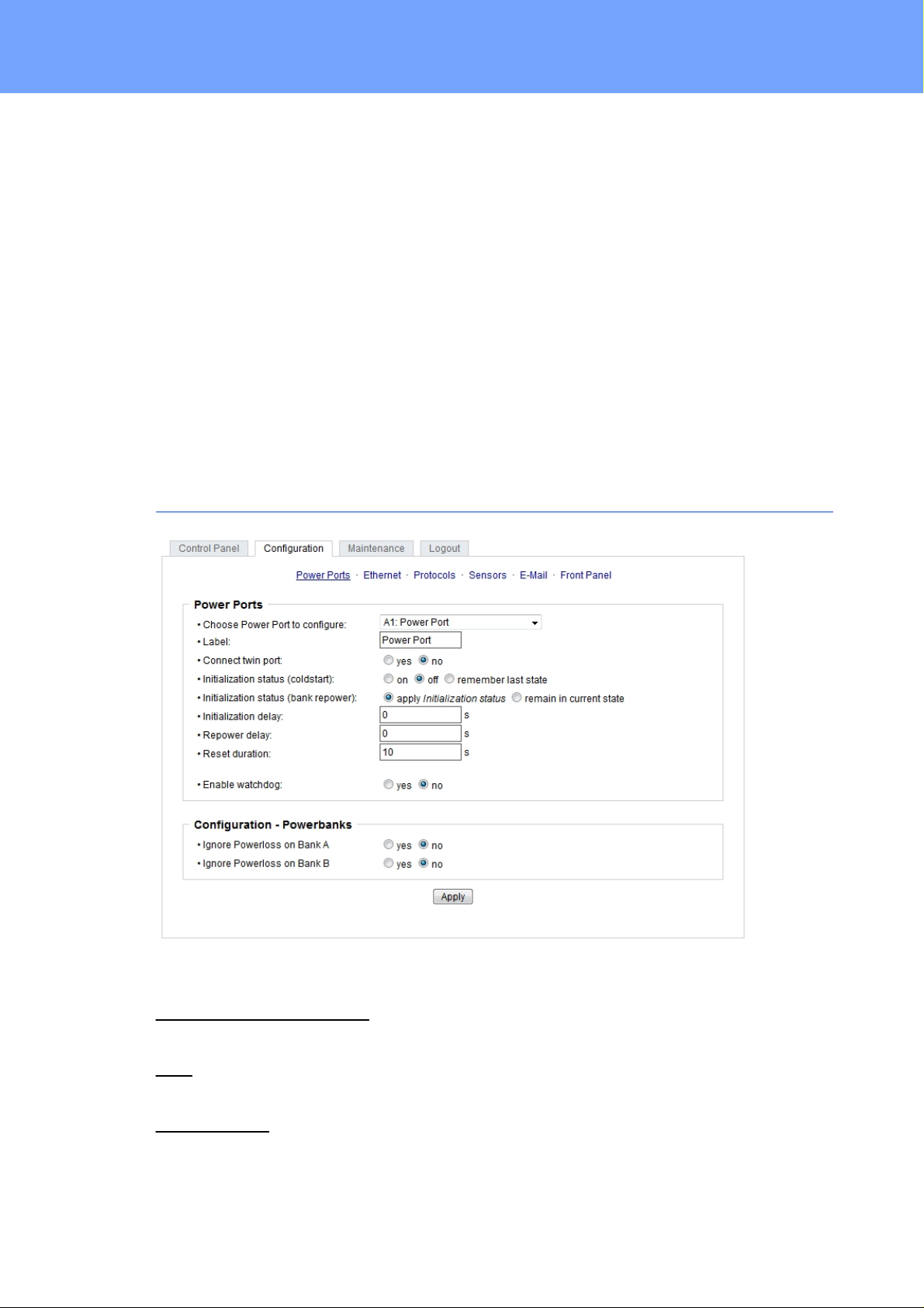
3.1 Power Ports
Choose Power Port to configure: This field is us ed to s elec t t he power ports to be configured.
Label: Y ou c an ass i gn a name up to 15 characters for each of the power ports. Using
the name, an identificati on of the the device connected to t he port can be facil it at ed.
Connect twinport: This option combines t wo relays of the same number of Bank A and
Bank B. E. g. A2 and B2. By t his c onnecti on a port always adopts the status of the connected port, so t hat both ports always have t he s ame s witching state.
23
Expert Power Control 8221/8226 © 2017 Gude Analog- und Digitalsysteme GmbH
Page 24

Configuration
Start-up Monit ori ng
It is important, that if necessary t he condition of the power ports c an be restored after a
power failure. Therefo re each port can be configured with Initialization st at us t o a s peci fic
start-up state. This s tart-up sequence can be carried out delayed by the parameter Initializ ati on Delay. There is in any case a minimum one-second delay between switc hing
of ports.
Initialization st at us (colds t art): This is t he port st at e (on, off, remember last state) the
port should be set when the device is turned on. The sett i ng "remember last state" s aves
the last manually set state of the power port in the EEP ROM.
Initialization st at us (bank repower): Had a bank not enough voltage, and is now adequately supplied again, the option "apply initialization st at us " l eads t o a repetition of
the st art-up sequence for this bank. Is " remain in current state" selected, t he port st at e
that is shown on display and web page is implemented.
Initialization delay: Here can be confi gured how long the port should wait to swit ch to its
defined state after the device is t urned on. The delay may las t up to 8191 seconds. This
corresponds t o a period of approx. t wo hours and 20 minutes. A value of zero means
that the initi aliz at ion is off.
3.1.1
Repower delay: When this feature is enabled (value greater than 0), the power port will
switc h itself on again a specified time after it has been disabled. Unlike the "Reset" button this function applies to all s witch actions, including SNMP, or an optional serial interface.
Reset Duration: When the "Reset" butt on is t riggered, the device turns the power port
off, waits for the tim e entered here (in seconds) and turns t he power port on.
Ignore Powerloss on Bank x: The power ports of bank x are not automatically s wit c hed
off when a voltage failure is detect ed, they keep their actual state.
This can lead to an increased total current c onsumpti on when the voltage is comi ng
back, since the act i vated connected devic es are simult aneously turned on again.
Activat ion of this option makes sense, if the input volt age of the device deviates strongly
from the si nusoidal shape. The internal signal evaluation might then erroneously ass ume
a voltage drop, because the zero-cross i ng characterist i c t ypical for sinusoidal voltage
curves is absent. One possible s ource of such non-sinusoidal voltage supply may be a
simple UPS t hat produces rectangular output voltages.
Watchdog
The watchdog feature enables t o m onitor various remote devic es. Therefore either ICMP
pings or TCP pings are sent t o t he devic e t o be monitored. If t hese pings are not
answered within a certain time (both the time and the number of attempt s can be set),
the port is reset. This allows e.g. t o automatically rest art not responding server or NAS
systems. The mode IP mas t er-slave port allows you to switc h a port depending on the
availability of a remote device.
When a watchdog is acti vated it presents various information in the Control Panel. The
information is c olor-coded.
·
Green text : The watchdog is act ive and regularly receives ping replies.
·
Orange text : The watc hdog is c urrently enabled, and waits for the first P i ng response.
24
Expert Power Control 8221/8226 © 2017 Gude Analog- und Digitalsysteme GmbH
Page 25

Configuration
·
Red text: The watc hdog is act i ve and receives no ping replies anym ore from the configured IP address.
After the watc hdog has been enabled, the display remains orange until the watchdog receives a ping response for the first time. Only t hen the watchdog is act i vated. Even after
triggering a watchdog and a subsequent power port reset, t he display will remain orange
until the devic e is rebooted and responds again to ping requests. This will prevent a premature watchdog reset of the port, e.g. when a s erver needs a long time for a file check.
You can monitor devices on your own network, as well as devi c es on an external network, e.g. t he operating status of a router.
Enable watc hdog: Enables the watchdog funct ion for this Power Port.
Watchdog type: Here you can choose between the monitoring by ICMP pings or TCP
pings.
·
ICMP P i ngs: The class ic ping (ICMP echo request ). It c an be used to check the accessibility of network devic es (for example, a server).
·
TCP Pings: With TCP pings, you can c heck if a TCP port on the target device would
accept a TCP connect. Therefore a non-blocked TCP port should be selected. A good
choice would be port 80 for http or port 25 for SMTP.
TCP port: Enter the TCP port to be monitored. When using ICMP pings this is not
needed.
Hostname: The name or IP address of the monitored network device.
Ping interval: S elec t the frequency (in s ec onds) at which the ping packet is sent to each
network devi ce to check its operating status.
Ping retries: After this number of consec uti ve unanswered ping request s the devic e is
considered inactive.
25
Expert Power Control 8221/8226 © 2017 Gude Analog- und Digitalsysteme GmbH
Page 26

Configuration
Watchdog mode: When Reset port when host down is enabled, the Power P ort is turned
off and switched back on after the time set in Reset Duration. In mode Switch off once
when host down the Power Port remains disabled.
At the default s et t i ng (Infinite wait for booting host after reset) the watchdog monitors t he
connected device. When there is no longer a reply after a set ti me, the watchdog performs t he s pecified action, us ually a reset of the Power Port. Now the watchdog waits
until the monitored device reports again on the network. This may take several minutes
depending on the boot duration of the device. Only when the device is ac c es sible from
network again, the watchdog is re-armed. If the option Repeat reset on booting host after
x ping timeout is enabled, t his m ec hanism is bypass ed. Now the watchdog is re-act ivated after N Ping intervals (input field ping timeouts).
When enabling the IP mas t er-slave mode, t he port is switched depending on the availability of a remote devic e. Depending on the configuration, the port is s wit c hed on when the
terminal is reachable, or vice versa.
Th e option Repeat reset on booting host after x ping timeout has the following pitfall:
If a s erver, t hat i s connected to t he monitored Port is in need for a long boot process
(e.g. it is doing a file sy stem c hec k ), t he s erver would probably exceed the tripping tim e
of the watchdog. The server would be switched off and on again, and the file syst em
check i s rest arted. This would be repeated endlessly.
3.2 Ethernet
3.2.1
IP Ad d r ess
26
Expert Power Control 8221/8226 © 2017 Gude Analog- und Digitalsysteme GmbH
Page 27

Configuration
Hostname: Here you c an enter a name with up to 63 characters. This name will be used
for registration on the DHCP s erver.
Special c haracters and umlauts can cause problems in the network.
IPv4 Address: The IP address of the device.
IPv4 Netmask : The network mask used in the network.
IPv4 Gateway address : The IP address of the gateway.
IPv4 DNS address: The IP address of the DNS s erver.
Use IPv4 DHCP: S elect "y es " if the TCP/IP settings s hould be obtained directly from the
DHCP s erver: When the function is selected, each t i me t he devic e powers up it is
check ed if a DHCP server is available on the network. If not, t he last used TCP/IP set t ing
will be used further.
Use IPv6 Protocol: A ctivates IPv6 usage.
Use IPv6 Router Advertisement: The Router Advertisement communicates with t he router
to make global IPv6 address es available.
Use DHCP v6: Request s from an exis t i ng DHCPv6 server address es of the configured
DNS server.
Use manual IPv6 address setti ngs: Act ivates t he entry of manual IP v6 addresses.
IPv6 st at us : Dis play s t he IPv6 addresses over which t he device can be accessed, and
additionally DNS and router addresses.
For IP changes a firmware reset is required. This can be done in the Maintenance
web page. A restart of the device leads by no means to a c hange of the relay st ates .
Manual IPv6 Configuration
27
Expert Power Control 8221/8226 © 2017 Gude Analog- und Digitalsysteme GmbH
Page 28

Configuration
The input fields for the manual set t ing of IPv6 address es allow you to configure the prefix
of four additional IPv6 device addresses, and to s et t wo DNS addresses , and a gateway.
3.2.2
IP ACL
Reply ICMP ping request s : If you enable this feature, t he devic e responds to ICMP pings
from the network.
Enable IP filter: Enable or disable the IP filter here. The IP filter represents an acc es s
control for incoming IP packets.
Please note that when IP access c ontrol is enabled HTTP and SNMP only work if
the appropriate servers and clients are registered in the IP acc es s control lis t .
If you choose a wrong IP ACL sett ing and locked yourself out, please acti vate the
Bootloader Mode and use GBL_Conf.exe t o deacti vate the IP ACL. Alternatively, y ou
can reset the devic e t o factory default.
28
Expert Power Control 8221/8226 © 2017 Gude Analog- und Digitalsysteme GmbH
Page 29

Configuration
3.2.3
HTTP
HTTP Server option: Select s whether acc es s is possible only with HTTP, HTTPS, or
both.
Server port HTTP: Here can be set the port number of the internal HTTP. Pos s i ble values ??
are from 1 to 65534 (default: 80). If you do not use the default port, you must append the
port number to the address wit h a c olon to address the devic e from a web browser. Suc h
as: " ht t p: / / 192.168.0.2:800"
Server port HTTPS; The port number to c onnect the web server vi a t he SS L (TLS) protocol.
Enable Ajax autorefresh: If this is act ivated, t he information of the status page is automatic ally updated via htt p request (AJAX).
For some HTTP configuration changes a firmware reset i s required. This can be
done in the Maintenance web page. A restart of the device leads by no means to a
change of the relay states .
Enable password protection: P as s word access protection can be acti vated. If the admin
password is ass igned, you c an only log in by entering this password to c hange settings.
Users can log in by entering the user pass word in order to query t he status information
and initiate switc hing operations.
Use radius server passwords: Username and password are validated by a Radius Sever.
Use locally s tored pass words: Username and password are st ored locally. In this case,
an admin pass word and a user password must be assigned. The password can have a
maximum of 31 characters. The name "admin" and "user" are provided for the user name
in the password entry m as k of the browser. In factory set t i ngs, t he pass word for the admin is set t o "admin" or "user" for the user password.
29
Expert Power Control 8221/8226 © 2017 Gude Analog- und Digitalsysteme GmbH
Page 30

Configuration
If the password mask is redisplayed, only four "bullets" are shown as a symbolic
placeholder, s inc e for security reasons t he device never stores the pass word itself, but
only the SHA2-256 hash. If you want t o c hange a password, t he c omplete pass word
must always be re-entered.
If you have forgotten your password, please activate the bootloader mode and then
turn off the password prompt in GBL_Conf.exe.
3.3 Protocols
3.3.1
Console
Enable Telnet: E nables Telnet console .
Telnet TCP port: Telnet s es sions are accepted on this port.
Raw mode: The VT100 editing and the IA C protocol are disabled.
Activat e echo: The echo setting if not changed by IAC.
Active negotiation: The IA C negotiation is init i ated by the server.
Require user login: Username and pass word are required.
Delay after 3 failed logins: A fter 3 wrong entries of username or password, the next login
attempt is delayed.
Use radius server passwords: Username and password are validated by a Radius Sever.
Use locally s tored pass words: Username and password are st ored locally.
30
Expert Power Control 8221/8226 © 2017 Gude Analog- und Digitalsysteme GmbH
Page 31

Configuration
Enable serial console: Enables the s erial console.
Raw mode: The VT100 editing is dis abled.
Activat e echo: The echo setting.
3.3.2
Enable binary KV M protocol: A dditi onally ac tivat es t he KV M protocol.
Enable UTF8 support: Enables c haracter encoding in UTF8.
Require user login: Us ername and password are required.
Delay after 3 failed logins: A fter 3 wrong entries of username or password, the next login
attempt is delayed.
Use radius server passwords: Username and password are validated by a Radius Sever.
Use locally s tored pass words: Username and password are st ored locally.
Syslog
Enable Sys log: E nables t he usage of Syslog Messages.
Syslog Server: If you have enabled Syslog Mes s ages, enter the IP address of the server
to which the sy slog information should be transmi t t ed.
31
Expert Power Control 8221/8226 © 2017 Gude Analog- und Digitalsysteme GmbH
Page 32

Configuration
3.3.3
SNMP
SNMP-get: Enables t he acc eptance of SNMP-GET commands.
SNMP-set: A ll ows t he reception of SNMP-SET comm ands.
SNMP UDP Port: S et s the UDP port where SNMP mess ages are received.
Enable SNMP v2: A ctivates SNMP v2.
Because of security issues, it is advis able to use only S NMP v3, and to disable
SNMP v2. Acces s es t o S NMP v2 are always ins ec ure.
Community public: The community pass word for SNMP GET requests .
Community private: The community pass word for SNMP SE T requests.
Enable SNMP v3: A ctivates SNMP v3.
SNMP v3 Username: The SNMP v3 User Name.
SNMP v3 Authorization Algorithm: The selected Authentic at ion Algorithm.
SNMP v3 Privac y Algorithm: S NMP v3 Enc rypt ion Algorithm. .
If the password mask is redisplayed, only four "bullets" are shown as a symbolic
placeholder, s inc e for security reasons t he device never stores the pass word itself, but
32
Expert Power Control 8221/8226 © 2017 Gude Analog- und Digitalsysteme GmbH
Page 33

Configuration
only the key formed using the Authorization Algorithm. If you want to c hange a pass word, the c omplete pass word must always be re-entered.
The calc ulation of the password hashes varies with the select ed algorithms. If the
Authenticat ion or Privac y algorithms are changed, the passwords must be re-entered in
the configuration dialog. "SHA-384" and "S HA512" are calculated purely in software. If
"SHA-512" is set on the configuration page, t he ti me for the key generation may take
once up to approx. 45 sec onds.
Send SNMP traps: Here you can specify whether, and in what format t he devic e s hould
send SNMP traps.
SNMP t rap receiver: You can insert here up to eight SNMP trap receiver.
MIB table: The download link to t he tex t file with the MIB table for the device.
More information about SNMP s ettings are available from our support or can be found on
the Internet at www.gude.info/wiki.
3.3.4
Radius
Enable Radius Client: E nables validation over Radius.
Use CHAP: Use CHAP password encoding.
Use Mess age Authenticat ion: A dds the "Mess age Authentic at ion" at t ribute to t he
Authenticat ion Request.
Primary Server: Name or IP address of the Primary Radius server.
Shared sec ret: Radius Shared Secret.
33
Expert Power Control 8221/8226 © 2017 Gude Analog- und Digitalsysteme GmbH
Page 34

Configuration
Timeout: How long (in seconds) will be waited for a response from an Authentication
Request.
Retries: How oft en an authentication request i s repeated aft er a timeout.
Use Back up Server: A ctivates a Radius Bac kup server.
Back up Server: Name or IP address of the Radius B ac k up s erver.
Shared sec ret: Radius Shared Secret.
Timeout: How long (in seconds) will be waited for a response from an Authentication
Request.
Retries: How oft en an authentication request i s repeated aft er a timeout.
3.3.5
Test Username: Username input field for Radius t es t .
Test P as sword: P assword input field for Radius tes t .
The "Test Radius Server" function allows you to c heck whether a combination of User-
name and Password is ac c epted by t he c onfigured Radius S ervers.
Modbus TCP
Enable Modbus TCP: Enables Modbus TCP support.
Modus TCP port: The TCP/IP port number for Modbus TCP.
34
Expert Power Control 8221/8226 © 2017 Gude Analog- und Digitalsysteme GmbH
Page 35

Configuration
3.4 Sensors
Choose power meter: Selec t s the measurement of Bank A or B.
Power meter name: The configurable name that will be display ed on the overview page
under "Line Name".
Enable AC current events: Enables the generation of AC current mess ages.
Maximum/ M inimum value: Adjus t able limit s for current levels (high and low), which
sends alerts via SNMP t raps, s yslog or E-Mail.
Hysteresis: This describes t he margin of when an event is generated aft er the measured
value has crossed the chosen limit.
35
Expert Power Control 8221/8226 © 2017 Gude Analog- und Digitalsysteme GmbH
Page 36

Configuration
Mess age channels: Enables t he generation of messages on different channels.
Choose s ensor port: Selects a t y pe of sensor to configure it. The first digit "1" indicates
the number of the sensor port (only important for devic es with more than one sensor
port). This is followed by the sensor name (e.g. 7002 for the hybrid sensor), a letter for
the sub-type sensor and the changeable sensor name. The sensor subtypes are defined
as: " T" = t emperature, "H" = humidity, " I" = sensor input.
Sensor Name: Changeable name for this s ensor. Temperature and humidity can have different names, even if they are from the same s ensor.
Enable sensor events: E nables t he generation of sensor messages.
Maximum/ M inimum value: Here you can choose whether, and at what Max i mum/ M in-
imum temperature or humidity m easurements lim it s the alerts are send via SNMP t raps,
sy slog or E-Mail.
Hysteresis: This describes t he margin of when an event is generated aft er the measured
value has crossed the chosen limit.
Mess age channels: Enables t he generation of messages on different channels.
Min/Max meas urement period: Selec t s the tim e range for the sensor min/max values on
the overview web page.
Enable beeper for AC alarms: Act ivates t he beeper for all AC limi t m es sages.
Enable beeper for sensor alarms: Activates the beep er fo r all sensor limit mes sages.
Hysteresis Example:
A Hys t eresis value prevents that t oo much m es s ages are generated, when a sensor
value is j it tering around a sensor limit . The following example shows the behavior for a
temperature sensor and a hysteresis value of "1". An upper limit of "50 °C" is set .
Example:
49.9 °C - is below the upper limit
50.0 °C - a mess age is generated for reaching the upper limit
50.1 °C - is above the upper limit
...
49.1 °C - is below the upper limit, but in t he hys teresis range
49.0 °C - is below the upper limit, but in t he hys teresis range
48.9 °C - a mess age is generated for underrunning the upper limit inclus i ve hys t eresis
range
...
3.4.1
Port S wi t c hing
Depending on the measured Current and the measured sensor values, s witching actions
can be triggered. During operation, t he act ions configured for crossing the limit s are executed. For example, when a value moves from the range "above max value" ins i de the
range "below max value", t he act i on defined for "below max value" is performed. In the
36
Expert Power Control 8221/8226 © 2017 Gude Analog- und Digitalsysteme GmbH
Page 37

Configuration
actual temperature
during configuration
actions
70 °C
Port A1 Off (above max) + Port A 2 On (above min)
45 °C
Port A1 On (below max) + Port A2 On (above mi n)
20 °C
Port A1 On (below max) + Port A2 Off (below min)
to "above max "
to "below max"
to "above min"
to "below min"
from "above max "
-
A1 On
A1 On
A1 On + A2 Off
from "below max"
A1 Off--
A2 Off
from "above min"
A1 Off--
A2 Off
from "below min"
A1 Off + A 2 On
A2 On
A2 On
-
case of device s t art, configuration or plug-in of t he s ensor, t he act ions corresponding to
the range in which the current t emperature is located are switched.
Example with " Max im um value" of 65 °C, "Mi nimum value" of 25 °C and hysteresis of 3 °
C. The dotted line shows the hysteresis.
Actions during confi guration, devic e s t art or plugging in the sensor (for given example):
Action matrix during operation when limit values are exceeded (for given example):
Only t he swit c hing operations for which actions have been defi ned, are triggered. If
no "On" or "Off" act ion is defined for a port, the port can never reach t his state by ex ceeding sensor values. Unless it is t he initi al s tate.
37
Expert Power Control 8221/8226 © 2017 Gude Analog- und Digitalsysteme GmbH
Page 38

Configuration
3.5 E-Mail
Enable E-Mail: Activates the E-Mail dispatch of messages.
Sender address: T he E-Mail addr ess of the sende r.
Recipient address: The E-Mail address of the recipient. A dditi onal E-Mail addresses,
separated by comma, c an be specified. The input limit is 100 characters.
SMTP Server: The SMTP IP-address of the E-Mail server. Ei t her as FQDN, e.g:
"mail. gmx .net", or as IP-address, e.g: " 213.165.64.20". If required, att ac h a designated
port, e.g: "mail.gmx.net:25".
SMTP server port: The port address of the E-Mail server. In the normal case this s hould
be the same as the default, that is determined by the setting SMTP Connection Sec urity.
SMTP Connection Sec urity: Transmission via SSL or no encryption.
SMTP Authentification (password): Aut hentic at ion method of the E-Mail Server.
Username: User name that is regist ered with the SMTP E-Mail server.
Set new password: Enter the password for the login to the E-Mail s erver.
Repeat password: Enter the password again to c onfirm it.
If the password mask is redisplayed, only four "bullets" are shown as a symbolic
placeholder, s inc e for security reasons t he pass word is never shown itself. If you want to
change a pass word, the complete pass word must always be re-entered.
E-Mail Logs: Logging of E -Mail sys tem mess ages.
38
Expert Power Control 8221/8226 © 2017 Gude Analog- und Digitalsysteme GmbH
Page 39

Configuration
3.6 Front Panel
Button Lock : Dis ables t he front butt ons (act i vates the key loc k) with the exception of the
bootloader activation.
Dark Dis play : The 7-segment display remains dark. Front button act i vity temporarily
switc hes t he display on.
Default Dis play: Selects what sensor is displayed in the display.
39
Expert Power Control 8221/8226 © 2017 Gude Analog- und Digitalsysteme GmbH
Page 40

Specifications
Page 41

Specifications
Entry in the IP ACL
Meaning
192.168.0.123
the PC with IP Address "192.168.0.123" can access the device
192.168.0.1/24
all devices of subnet "192.168.0.1/24" can access the device
1234:4ef0:eec1:0::/64
all devices of subnet "1234:4ef0:eec1:0::/64" can access the
device
4 Specifications
4.1 IP ACL
IP Access Control List
The IP Acc es s Control List (ACL IP) is a filter for incoming IP packet s . If the filter is active, only t he hosts and subnets whose IP addresses are registered in the list, can contact via HTTP or SNMP, and make changes. For incoming connecti ons from unauthorized PCs, t he devic e is not completely transparent. Due to tec hnical rest raints , a TCP/IP
connection will be accepted at first, but then rejected directly.
Examples:
If you choose a wrong IP ACL sett ing and locked yourself out, please acti vate the
Bootloader Mode and use GBL_Conf.exe t o deacti vate the IP ACL. Alternatively, y ou
can reset the devic e t o factory default.
4.2 IPv6
IPv6 Addresses
IPv6 address es are 128 bit l ong and thus four times as long as IPv4 addresses . The fi rst
64 bit form a so-called prefix, t he las t 64 bit desi gnate a unique interface identifier. The
prefix is composed of a routing prefix and a subnet ID. An IPv6 network interface can be
reached under several IP addresses. Us ually t his is t he cas e under a global address and
the link loc al address.
Address Notation
IPv6 address es are noted in 8 hexadecimal blocks at 16 bit, while IPv4 normally is noted
in decimal. The seperator is a colon, not a period.
E.g.: 1234:4ef0: 0:0: 0019:32ff:fe00:0124
Leading zeros may be omit t ed within a block. The previous example c an be rewritten as:
1234:4ef0:0:0:19:32ff:fe00:124
One may omit one or more suc c es sive blocks , if they consist of zeros. This may be
41
Expert Power Control 8221/8226 © 2017 Gude Analog- und Digitalsysteme GmbH
Page 42

Specifications
Interface
Scope of Acces s
HTTP
read / write all c onfiguration data
done only once within an IPv6 address !
1234:4ef0::19:32ff:fe00:124
One may use the usual decimal notation of IPv4 for the last 4 bytes:
1234:4ef0::19:32ff:254.0.1.36
4.3 Radius
The passwords for HTTP, t elnet, and serial console (depending on the model) can be
stored locally and / or authenticated via RADIUS. The RADIUS configuration supports a
primary server and a backup s erver. If the primary s erver does respond, the RADIUS request is sent to the back up server. If the local password and RADIUS are enabled at the
same tim e, t he s y stem is first c heck i ng locally, and then in the event of a failure the
RADIUS servers are contact ed.
RADIUS attributes
The following RADIUS attributes are evaluated by the client:
Session-Timeout: This attribute speci fies (in sec onds) how long an accepted RADIUS
request is valid. A fter this t i me has elapsed, t he RADIUS s erver must be prompted
again. If this att ribute is not returned, the default timeout entry from the configuration is
used instead.
Filter-Id: If the value "admin" is s et for this att ribute, then an admin rights are assigned
for the login, otherwise only user access.
Service-Type: This is an alternative to Fi lt er-Id. A servic e t y pe of "6" or "7" means admin rights for the HTTP l ogin, otherwise only limited user access .
HTTP Login
The HTTP login takes plac e via Basic Authentic at ion. This means t hat it is the responsibility of the web server, how long the login credentials are temporarily s tored there. The
RADIUS parameter "Ses sion-Tim eout" t herefore does not determine when the user has
to login again, but at what intervals the RADIUS s ervers are asked again.
4.4 Automated Access
The device c an be acces sed automatically via four different interfaces, which offer different possibilities t o access t he c onfiguration data and status information. Only http and
the console (telnet and serial) provide full access t o t he devic e.
List of different acc es s options (if supported by t he model):
Expert Power Control 8221/8226 © 2017 Gude Analog- und Digitalsysteme GmbH
42
Page 43

Specifications
read / write all s t at us i nformation
Console
read / write all c onfiguration data
read / write all s t at us i nformation
SNMP
read / write s t at us of Power Ports (relays)
read / write names of Power Ports (relays)
read / write s t at us of Port st art configuration
read / write s t at us B uz zer
read measurement values of external sensors
read measurement values of all energy s ensors
resetting the energy meters
read the status of Overvoltage Protect ion
Modbus TCP
read / write s t at us of Power Ports (relays)
read status of Inputs
read measurement values of external sensors
read measurement values of all energy s ensors
The device c an be controlled via HTTP interfac e with CGI commands and returns the internal configuration and stat us i n JSON format. The structure of the CGI commands and
the JSON data is explained in more detail in our Wiki article:
http://wiki.gude.info/EPC_HTTP_Interface
52
43
69
4.5 SNMP
SNMP c an be used for st atus i nformation via UDP (port 161). Supported SNMP c ommands are:
·
GET
·
GETNEXT
·
GETBULK
·
SET
To query via SNMP you need a Network M anagement Sys t em, such as HP OpenView,
OpenNMS, Nagios etc . , or the sim ple c ommand line tools of NET-SNMP software. The
device s upports S NMP protocols v1, v2c and v3. If traps are enabled in the configuration,
the device mes sages are sent as notifications (traps). S NMP Informs are not supported.
SNMP Requests are answered with the same versi on with which they were sent. The
version of the sent traps can be set i n t he configuration.
MIB Tables
The values that c an be request ed or changed by t he devic e, t he s o-called "Managed Objects", are described in Management Information Bas es (MIBs). These substructures are
subordinate to s o-called "OID" (Object Identifiers). An OID digit signifies the location of a
value inside a MIB st ruct ure. Al t ernatively, each OID can be referred to with it s symbol
name (subtree name). The device's MIB table can be displayed as a tex t file by c li c king
on the link "MIB t able" on the SNMP configuration page in the browser.
SNMP v1 and v2c
43
Expert Power Control 8221/8226 © 2017 Gude Analog- und Digitalsysteme GmbH
SNMP v1 and v2c authenticates t he network requests by s o-called c ommuniti es. The
SNMP request has to s end along the so-called community public for queries (read ac-
Page 44

Specifications
cess) and the community privat e for status changes (write acc es s) . The SNMP
communities are read and write pass words. In SNMP v1 and v2 the communities are
transmitt ed unencrypted on the network and can be easily intercepted with IP sniffers
within this collision domain. To enforce limited access we recommend the use of DMZ or
IP-ACL.
SNMP v3
Because t he devic e has no multi us er management, only one user (default name "standard") is detected in SNMP v3. From t he User-based Sec urity M odel (USM) MIB variables, there is a s upport of "us mStats . . ." c ounter. The "us mUs er .. . " variables will be
added with the enhancement of additional users i n later firmware versions. The system
has only one context . The sys t em ac cepts t he c ontex t "normal" or an empty context.
Authentication
The algorithms "HMAC-MD5-96" and "HMAC-SHA-96" are available for authentic ati on. In
addition, the "HMAC-SHA-2" variants (RFC7630) "SHA-256", "SHA-384" and "SHA-512"
are implemented.
"SHA-384" and "SHA512" are calculated purely in s oftware. If "SHA-384" or "SHA-
512" is s et on the configuration page, the time for the key generation may tak e once up
to approx. 45 s ec onds.
Encryption
The methods "DES" , "3DES" , " A E S -128", " A ES-192" and "AES-256" are supported in
combination with "HMAC-MD5-96" and "HMAC-SHA-96." For the "HMAC-SHA-2" protocols, there is c urrently neither RFC nor draft that will allow for cooperation with an encryption.
W hile in the s ettings "A E S-192" and "AES256" the key calculation is based on
"draft-blumenthalphoto-aes-usm-04", the methods "A E S 192-3DESKey " and "AE S 2563DESKey" ut il ize a key generation, which is also us ed in the "3DES" c onfiguration
("draft -reeder-snmpv3-usm-3desede-00"). If one is not an SNMP expert, it is recommended to try in each cas e t he set t ings with and without "...- 3DESKey " .
Passwords
The passwords for authentication and encrypt ion are stored only as computed hashes
for security reasons. Thus it is , i f at all, very difficult to infer the initial pass word.
However, the hash c alc ulation c hanges with the set algorithms. If the authentic at ion or
privacy algorithms are changed, the passwords must be re-entered in the configuration
dialog.
Security
The following aspects should be consi dered:
·
If encry ption or authentication is us ed, t hen SNMP v1 and v2c s hould be turned off.
Otherw ise the device could be accessed with it.
·
If only authentic ation is us ed, t hen the new "HMAC-SHA-2" met hods are superior to
the MD5 or SHA-1 hashing algorithms . Since only S HA-256 is acc elerated in hardware, and SHA-384 and SHA-512 are calculated purely in software, one should normally select S HA-256. From a cryptographic point of view, the security of SHA-256 is
44
Expert Power Control 8221/8226 © 2017 Gude Analog- und Digitalsysteme GmbH
Page 45

Specifications
Name
OID
Type
Acc.
Description
epc8221TrapCtrl
.56.1.1.1.1.0
Integer32
RW
0 = off 1 = Ver. 1 2 = Ver. 2c 3 = Ver. 3
suffici ent for today's usage.
·
For SHA-1, there are a little les s attack scenarios than MD5. If in doubt, SHA-1 is
preferable.
·
Encrypt ion "DES " is consi dered very unsafe, use only in an emergency for reasons of
compatibility!
·
For cryptologists it's a debatable point whether "HMAC-MD5-96" and "HMAC-SHA-96"
can must er enough entropy for key l engths of "AE S -192" or "AES -256".
·
From the foregoing considerations, we would recommended at present " HMAC-SHA96" with "AE S -128" as authenticat ion and encryption method.
NET-SNMP
NET-SNMP provides a very widespread collect ion of SNMP command-line tools (snmpget, s nmpset , s nmpwalk etc.) NET-SNMP is among others available for Linux and Windows. After installing NET-SNMP y ou s hould create the device-speci fic MIB of the device
in NET-SMP share directory, e.g. after
c:\usr\share\snmp\mibs
4.5.1
or
/usr/share/snmp/mibs
So later you can use the 'subtree names' instead of OIDs:
Name: snmp w a lk -v2c - m ALL -c public 192.16 8 .1.232 gudead s
OID: s nmpwal k - v 2c -mAL L -c public 19 2.168. 1 .232 1. 3.6.1. 4.1.28 5 07
NET-SNMP Exampl es
Query Power Port 1 swit c hing state:
snmpget -v2c -mA LL -c public 192.168.1.232 epc822XPortState.1
Switc h on Power Port 1:
snmpset -v2c -mALL -c private 192.168.1.232 epc822XP ortSt at e.1 i nteger 1
Device MIB 8221
Below is a table of all devi c e-speci fic OID 's which can be access ed via SNMP. In the
numerical representation of the OID the prefix " 1. 3. 6.1. 4.1. 28507 " (Gude Enterprise
OID) was omitted at each entry in t he table to preserve space. The example for a complete OID would be "1.3.6.1. 4.1. 28507.56.1.1.1.1". A distinc t ion is made in SNMP OID 's
in between tables and sc alars. OID scalar have the extensi on ". 0" and only spec ify a
value. In SNMP tables t he "x" is replaced by an index (1 or greater) to address a value
from the table.
45
Expert Power Control 8221/8226 © 2017 Gude Analog- und Digitalsysteme GmbH
Page 46

Specifications
epc8221TrapIPIndex
.56.1.1.1.2.1.1.x
Integer32
RO
A unique value, greater than zero, for each receiver slot.
epc8221TrapAddr
.56.1.1.1.2.1.2.x
OCTETS
RW
DNS name or IP address specifying o ne Trap receiver slot. A port can
optionally be specified: 'name:port' An empty string disables this slot.
epc8221portNumber
.56.1.3.1.1.0
Integer32
RO
The number of Relay Ports
epc8221PortIndex
.56.1.3.1.2.1.1.x
Integer32
RO
A unique value, greater than zero, for each Relay Port.
epc8221PortName
.56.1.3.1.2.1.2.x
OCTETS
RW
A textual string containing n ame of a Relay Port.
epc8221PortState
.56.1.3.1.2.1.3.x
INTEGER
RW
current state of a Relay Port
epc8221PortSw itchCount
.56.1.3.1.2.1.4.x
Integer32
RO
The total number of sw itch actions ocurred on a Relay Port. Does not
count sw itch commands w hich will not switch the ral ay state, so just
real relay sw itches are displayed here.
epc8221PortStartupMode
.56.1.3.1.2.1.5.x
INTEGER
RW
set Mode of startup sequence (off, on , remember last state)
epc8221PortStartupDelay
.56.1.3.1.2.1.6.x
Integer32
RW
Delay in sec for startup action
epc8221PortRepowerTime
.56.1.3.1.2.1.7.x
Integer32
RW
Delay in sec for repow er port after sw itching off
epc8221Buzzer
.56.1.3.10.0
Integer32
RW
turn Buzzer on and off
epc8221ActivePow erChan
.56.1.5.1.1.0
Unsigned32
RO
Number of suppported Pow er Chann els.
epc8221Pow erIndex
.56.1.5.1.2.1.1.x
Integer32
RO
Index of Pow er Channe l entries
epc8221ChanStatus
.56.1.5.1.2.1.2.x
Integer32
RO
0 = data not active, 1 = data val id
epc8221AbsEnergyActive
.56.1.5.1.2.1.3.x
Gauge32
RO
Absolute Active Energy counter.
epc8221Pow erActive
.56.1.5.1.2.1.4.x
Integer32
RO
Active Pow er
epc8221Current
.56.1.5.1.2.1.5.x
Gauge32
RO
Actual Curent on Power Channel.
epc8221Voltage
.56.1.5.1.2.1.6.x
Gauge32
RO
Actual Voltage on Pow er Channel
epc8221Frequency
.56.1.5.1.2.1.7.x
Gauge32
RO
Frequency of Pow er Channel
epc8221Pow erFactor
.56.1.5.1.2.1.8.x
Integer32
RO
Pow er Factor of Channel between -1.0 and 1.00
epc8221Pangle
.56.1.5.1.2.1.9.x
Integer32
RO
Phase Angle between Voltage and L Line Current between -180.0 and
180.0
epc8221Pow erApparent
.56.1.5.1.2.1.10.x
Integer32
RO
L Line Mean Apparent Pow er
epc8221Pow erReactive
.56.1.5.1.2.1.11.x
Integer32
RO
L Line Mean Reactive Pow er
epc8221AbsEnergyReactive
.56.1.5.1.2.1.12.x
Gauge32
RO
Absolute Reactive E nergy counter.
epc8221AbsEnergyActiveResettable
.56.1.5.1.2.1.13.x
Gauge32
RW
Resettable Absolute Active Energy counter. Writi ng '0' resets all resettable counter.
epc8221AbsEnergyReactiveResettable
.56.1.5.1.2.1.14.x
Gauge32
RO
Resettable Absolute Reactive Energy counter.
epc8221ResetTime
.56.1.5.1.2.1.15.x
Gauge32
RO
Time in seconds since last Energy Counter reset.
epc8221Forw EnergyActive
.56.1.5.1.2.1.16.x
Gauge32
RO
Forward Active Energy counter.
epc8221Forw EnergyReactive
.56.1.5.1.2.1.17.x
Gauge32
RO
Forward Reactive Energy counter.
Expert Power Control 8221/8226 © 2017 Gude Analog- und Digitalsysteme GmbH
46
Page 47

Specifications
epc8221Forw EnergyActiveResettable
.56.1.5.1.2.1.18.x
Gauge32
RO
Resettable Forward Active Energy counter.
epc8221Forw EnergyReactiveResettable
.56.1.5.1.2.1.19.x
Gauge32
RO
Resettable Forward Reactive E nergy counter.
epc8221RevEnergyActive
.56.1.5.1.2.1.20.x
Gauge32
RO
Reverse Active Energy counter.
epc8221RevEnergyReactive
.56.1.5.1.2.1.21.x
Gauge32
RO
Reverse Reactive E nergy counter.
epc8221RevEnergyActiveResettable
.56.1.5.1.2.1.22.x
Gauge32
RO
Resettable Reverse Active En ergy counter.
epc8221RevEnergyReactiveResettable
.56.1.5.1.2.1.23.x
Gauge32
RO
Resettable Reverse Reactive Energy counter.
epc8221OVPIndex
.56.1.5.2.1.1.x
Integer32
RO
None
epc8221OVPStatus
.56.1.5.2.1.2.x
INTEGER
RO
shows the status of the built-in Overvoltage Protection
epc8221SensorIndex
.56.1.6.1.1.1.x
Integer32
RO
None
epc8221TempSensor
.56.1.6.1.1.2.x
Integer32
RO
actual temperature
epc8221HygroSensor
.56.1.6.1.1.3.x
Integer32
RO
actual humidity
epc8221InputSensor
.56.1.6.1.1.4.x
INTEGER
RO
logical state of input sensor
Name
OID
Type
Acc.
Description
epc8226TrapCtrl
.58.1.1.1.1.0
Integer32
RW
0 = off 1 = Ver. 1 2 = Ver. 2c 3 = Ver. 3
epc8226TrapIPIndex
.58.1.1.1.2.1.1.x
Integer32
RO
A unique value, greater than zero, for each receiver slot.
epc8226TrapAddr
.58.1.1.1.2.1.2.x
OCTETS
RW
DNS name or IP address specifying o ne Trap receiver slot. A port can
optionally be specified: 'name:port' An empty string disables this slot.
epc8226portNumber
.58.1.3.1.1.0
Integer32
RO
The number of Relay Ports
epc8226PortIndex
.58.1.3.1.2.1.1.x
Integer32
RO
A unique value, greater than zero, for each Relay Port.
epc8226PortName
.58.1.3.1.2.1.2.x
OCTETS
RW
A textual string containing n ame of a Relay Port.
epc8226PortState
.58.1.3.1.2.1.3.x
INTEGER
RW
current state of a Relay Port
epc8226PortSw itchCount
.58.1.3.1.2.1.4.x
Integer32
RO
The total number of sw itch actions ocurred on a Relay Port. Does not
count sw itch commands w hich will not switch the ral ay state, so just
real relay sw itches are displayed here.
4.5.2
Device MIB 8226
Below is a table of all devi c e-speci fic OID 's which can be access ed via SNMP. In the
numerical representation of the OID the prefix " 1. 3. 6.1. 4.1. 28507 " (Gude Enterprise
OID) was omitted at each entry in t he table to preserve space. The example for a complete OID would be "1.3.6.1. 4.1. 28507.58.1.1.1.1". A distinc t ion is made in SNMP OID 's
in between tables and sc alars. OID scalar have the extensi on ". 0" and only spec ify a
value. In SNMP tables t he "x" is replaced by an index (1 or greater) to address a value
from the table.
47
Expert Power Control 8221/8226 © 2017 Gude Analog- und Digitalsysteme GmbH
Page 48

Specifications
epc8226PortStartupMode
.58.1.3.1.2.1.5.x
INTEGER
RW
set Mode of startup sequence (off, on , remember last state)
epc8226PortStartupDelay
.58.1.3.1.2.1.6.x
Integer32
RW
Delay in sec for startup action
epc8226PortRepowerTime
.58.1.3.1.2.1.7.x
Integer32
RW
Delay in sec for repow er port after sw itching off
epc8226Buzzer
.58.1.3.10.0
Integer32
RW
turn Buzzer on and off
epc8226ActivePow erChan
.58.1.5.1.1.0
Unsigned32
RO
Number of suppported Pow er Chann els.
epc8226Pow erIndex
.58.1.5.1.2.1.1.x
Integer32
RO
Index of Pow er Channe l entries
epc8226ChanStatus
.58.1.5.1.2.1.2.x
Integer32
RO
0 = data not active, 1 = data val id
epc8226AbsEnergyActive
.58.1.5.1.2.1.3.x
Gauge32
RO
Absolute Active Energy counter.
epc8226Pow erActive
.58.1.5.1.2.1.4.x
Integer32
RO
Active Pow er
epc8226Current
.58.1.5.1.2.1.5.x
Gauge32
RO
Actual Curent on Power Channel.
epc8226Voltage
.58.1.5.1.2.1.6.x
Gauge32
RO
Actual Voltage on Pow er Channel
epc8226Frequency
.58.1.5.1.2.1.7.x
Gauge32
RO
Frequency of Pow er Channel
epc8226Pow erFactor
.58.1.5.1.2.1.8.x
Integer32
RO
Pow er Factor of Channel between -1.0 and 1.00
epc8226Pangle
.58.1.5.1.2.1.9.x
Integer32
RO
Phase Angle between Voltage and L Line Current between -180.0 and
180.0
epc8226Pow erApparent
.58.1.5.1.2.1.10.x
Integer32
RO
L Line Mean Apparent Pow er
epc8226Pow erReactive
.58.1.5.1.2.1.11.x
Integer32
RO
L Line Mean Reactive Pow er
epc8226AbsEnergyReactive
.58.1.5.1.2.1.12.x
Gauge32
RO
Absolute Reactive E nergy counter.
epc8226AbsEnergyActiveResettable
.58.1.5.1.2.1.13.x
Gauge32
RW
Resettable Absolute Active Energy counter. Writi ng '0' resets all resettable counter.
epc8226AbsEnergyReactiveResettable
.58.1.5.1.2.1.14.x
Gauge32
RO
Resettable Absolute Reactive Energy counter.
epc8226ResetTime
.58.1.5.1.2.1.15.x
Gauge32
RO
Time in seconds since last Energy Counter reset.
epc8226Forw EnergyActive
.58.1.5.1.2.1.16.x
Gauge32
RO
Forward Active Energy counter.
epc8226Forw EnergyReactive
.58.1.5.1.2.1.17.x
Gauge32
RO
Forward Reactive Energy counter.
epc8226Forw EnergyActiveResettable
.58.1.5.1.2.1.18.x
Gauge32
RO
Resettable Forward Active Energy counter.
epc8226Forw EnergyReactiveResettable
.58.1.5.1.2.1.19.x
Gauge32
RO
Resettable Forward Reactive E nergy counter.
epc8226RevEnergyActive
.58.1.5.1.2.1.20.x
Gauge32
RO
Reverse Active Energy counter.
epc8226RevEnergyReactive
.58.1.5.1.2.1.21.x
Gauge32
RO
Reverse Reactive E nergy counter.
epc8226RevEnergyActiveResettable
.58.1.5.1.2.1.22.x
Gauge32
RO
Resettable Reverse Active En ergy counter.
epc8226RevEnergyReactiveResettable
.58.1.5.1.2.1.23.x
Gauge32
RO
Resettable Reverse Reactive Energy counter.
epc8226OVPIndex
.58.1.5.2.1.1.x
Integer32
RO
Expert Power Control 8221/8226 © 2017 Gude Analog- und Digitalsysteme GmbH
48
Page 49

Specifications
None
epc8226OVPStatus
.58.1.5.2.1.2.x
INTEGER
RO
shows the status of the built-in Overvoltage Protection
epc8226spActivePowerChan
.58.1.5.5.1.0
Unsigned32
RO
Number of Single Port Power Channels. Value i s zero on EPC 8220
series.
epc8226spPowerIndex
.58.1.5.5.2.1.1.x
Integer32
RO
Index of Single Port P ower Channel entries. Indices 0-5 mean Ports A1
to A6, 6-11 are Ports B1 to B6.
epc8226spChanStatus
.58.1.5.5.2.1.2.x
Integer32
RO
0 = data not active, 1 = data val id
epc8226spAbsEnergyActive
.58.1.5.5.2.1.3.x
Gauge32
RO
Absolute Active Energy counter.
epc8226spPowerActive
.58.1.5.5.2.1.4.x
Integer32
RO
Active Pow er
epc8226spCurrent
.58.1.5.5.2.1.5.x
Gauge32
RO
Actual Curent on Power Channel.
epc8226spVoltage
.58.1.5.5.2.1.6.x
Gauge32
RO
Actual Voltage on Pow er Channel
epc8226spFrequency
.58.1.5.5.2.1.7.x
Gauge32
RO
Frequency of Pow er Channel
epc8226spPowerFactor
.58.1.5.5.2.1.8.x
Integer32
RO
Pow er Factor of Channel between -1.0 and 1.00
epc8226spPangle
.58.1.5.5.2.1.9.x
Integer32
RO
Phase Angle between Voltage and L Line Current between -180.0 and
180.0
epc8226spPowerApparent
.58.1.5.5.2.1.10.x
Integer32
RO
L Line Mean Apparent Pow er
epc8226spPowerReactive
.58.1.5.5.2.1.11.x
Integer32
RO
L Line Mean Reactive Pow er
epc8226spAbsEnergyReactive
.58.1.5.5.2.1.12.x
Gauge32
RO
Absolute Reactive E nergy counter.
epc8226spAbsEnergyActiveResettable
.58.1.5.5.2.1.13.x
Gauge32
RW
Resettable Absolute Active Energy counter. Writi ng '0' resets all resettable counter.
epc8226spAbsEnergyReactiveResettable
.58.1.5.5.2.1.14.x
Gauge32
RO
Resettable Absolute Reactive Energy counter.
epc8226spResetTime
.58.1.5.5.2.1.15.x
Gauge32
RO
Time in seconds since last Energy Counter reset.
epc8226spForwEnergyActive
.58.1.5.5.2.1.16.x
Gauge32
RO
Forward Active Energy counter.
epc8226spForwEnergyReactive
.58.1.5.5.2.1.17.x
Gauge32
RO
Forward Reactive Energy counter.
epc8226spForwEnergyActiveResettable
.58.1.5.5.2.1.18.x
Gauge32
RO
Resettable Forward Active Energy counter.
epc8226spForwEnergyReactiveResettable
.58.1.5.5.2.1.19.x
Gauge32
RO
Resettable Forward Reactive E nergy counter.
epc8226spRevEnergyActive
.58.1.5.5.2.1.20.x
Gauge32
RO
Reverse Active Energy counter.
epc8226spRevEnergyReactive
.58.1.5.5.2.1.21.x
Gauge32
RO
Reverse Reactive E nergy counter.
epc8226spRevEnergyActiveResettable
.58.1.5.5.2.1.22.x
Gauge32
RO
Resettable Reverse Active En ergy counter.
epc8226spRevEnergyReactiveResettable
.58.1.5.5.2.1.23.x
Gauge32
RO
Resettable Reverse Reactive Energy counter.
epc8226SensorIndex
.58.1.6.1.1.1.x
Integer32
RO
None
epc8226TempSensor
.58.1.6.1.1.2.x
Integer32
RO
actual temperature
49
Expert Power Control 8221/8226 © 2017 Gude Analog- und Digitalsysteme GmbH
Page 50

Specifications
epc8226HygroSensor
.58.1.6.1.1.3.x
Integer32
RO
actual humidity
epc8226InputSensor
.58.1.6.1.1.4.x
INTEGER
RO
logical state of input sensor
4.6 SSL
TLS Standard
The device is c ompatible with t he st andards TLSv1.0 to TLSv1.2. Due to lack of security,
SSLv3.0 as well as RC4 and DES encrypt ions are deactivat ed.
The following TLS Ciphersuites are supported:
·
TLS_RSA_WITH_3DES_EDE_CBC_SHA
·
TLS_DHE_RSA_WITH_3DES_EDE_CBC_SHA
·
TLS_RSA_WITH_AES_128_CBC_SHA
·
TLS_DHE_RSA_WITH_AES_128_CBC_SHA
·
TLS_RSA_WITH_AES_256_CBC_SHA
·
TLS_DHE_RSA_WITH_AES_256_CBC_SHA
·
TLS_RSA_WITH_AES_128_CBC_SHA256
·
TLS_RSA_WITH_AES_256_CBC_SHA256
·
TLS_DHE_RSA_WITH_AES_128_CBC_SHA256
·
TLS_DHE_RSA_WITH_AES_256_CBC_SHA256
·
TLS_RSA_WITH_AES_128_GCM_SHA256
·
TLS_DHE_RSA_WITH_AES_128_GCM_SHA256
·
TLS_PSK_WITH_AES_128_GCM_SHA256
·
TLS_PSK_WITH_AES_128_CBC_SHA256
·
TLS_ECDH_ECDSA_WITH_3DES_EDE_CBC_SHA
·
TLS_ECDH_ECDSA_WITH_AES_128_CBC_SHA
·
TLS_ECDH_ECDSA_WITH_AES_256_CBC_SHA
·
TLS_ECDHE_ECDSA_WITH_3DES_EDE_CBC_SHA
·
TLS_ECDHE_ECDSA_WITH_AES_128_CBC_SHA
·
TLS_ECDHE_ECDSA_WITH_AES_256_CBC_SHA
·
TLS_ECDH_RSA_WITH_3DES_EDE_CBC_SHA
·
TLS_ECDH_RSA_WITH_AES_128_CBC_SHA
·
TLS_ECDH_RSA_WITH_AES_256_CBC_SHA
·
TLS_ECDHE_RSA_WITH_3DES_EDE_CBC_SHA
·
TLS_ECDHE_RSA_WITH_AES_128_CBC_SHA
·
TLS_ECDHE_RSA_WITH_AES_256_CBC_SHA
·
TLS_ECDHE_ECDSA_WITH_AES_128_CBC_SHA256
·
TLS_ECDH_ECDSA_WITH_AES_128_CBC_SHA256
·
TLS_ECDHE_RSA_WITH_AES_128_CBC_SHA256
·
TLS_ECDH_RSA_WITH_AES_128_CBC_SHA256
·
TLS_ECDHE_ECDSA_WITH_AES_128_GCM_SHA256
·
TLS_ECDH_ECDSA_WITH_AES_128_GCM_SHA256
·
TLS_ECDHE_RSA_WITH_AES_128_GCM_SHA256
·
TLS_ECDH_RSA_WITH_AES_128_GCM_SHA256
·
TLS_RSA_WITH_AES_128_CCM
·
TLS_RSA_WITH_AES_256_CCM
·
TLS_DHE_RSA_WITH_AES_128_CCM
·
TLS_DHE_RSA_WITH_AES_256_CCM
·
TLS_RSA_WITH_AES_128_CCM_8
·
TLS_RSA_WITH_AES_256_CCM_8
·
TLS_DHE_RSA_WITH_AES_128_CCM_8
·
TLS_DHE_RSA_WITH_AES_256_CCM_8
·
TLS_ECDHE_RSA_WITH_CHACHA20_POLY1305_SHA256
Expert Power Control 8221/8226 © 2017 Gude Analog- und Digitalsysteme GmbH
50
Page 51

Specifications
·
TLS_ECDHE_ECDSA_WITH_CHACHA20_POLY1305_SHA256
·
TLS_DHE_RSA_WITH_CHACHA20_POLY1305_SHA256
Creating your own Certifi cat es
The SSL stack is supplied with a specially newly generated certificate. There is no function to
generate the local certificate anew at the touch of a button, since the required random numbers in an embedded dev ice are usually not independent enough. However, you can create
new certificates and import them to the device. The server accepts RSA (1024/2048/4096) and
ECC (Elliptic Curve Cry ptography) certificates.
Usually O penSSL is used to create an SSL certificate. For Windows for ex ample, there is the
light version of Shinning Light Productions. There you open a command prompt, change to
the directory " C:\ O penSSL-Win32\bin" and set these environment variables:
set openssl _ conf=C : \OpenS S L-Win3 2 \bin\o p enssl. c fg
set RANDFIL E =C:\Op e nSSL-W i n32\bi n \.rnd
Here are some examples for the generation with OpenSSL:
Creation of a self-signed RSA 2048-bit certificat e
opens sl genr sa -out s e rver.k e y 2048
opens sl req -new -x 509 -da ys 365 -key se rver.k e y -out server . crt
RSA 2048-bit c ertificat e with Si gn Request :
opens sl genr sa -out s e rver.k e y 2048
opens sl req -new -k ey serv er.key -out se rver.c s r
opens sl req -x509 - days 36 5 -key server . key -in s e rver.c s r -out server .crt
The server key s s hould be generated with " openssl genrsa". If in the generated key
file it reads only " ----- BEGIN PRIVATE KEY -----" and not "----- BEGIN RSA PRIVATE
KEY -----", the key is not recognized.
ECC Certificate with Sign Request:
opens sl ecpa ram -ge nkey -n ame pri me256v 1 - o ut serv er.key
opens sl req -new -k ey serv er.key -out se rver.c s r
opens sl req -x509 - days 36 5 -key server . key -in s e rver.c s r -out server .crt
If you have created your key and certificate, both files are concatenated to one fil e:
Linux:
cat server. c rt serv er.key > serve r.pem
Windows:
copy server . crt + server. k ey serv er.pem
The created server.pem can only be uploaded in the maintenance s ec t ion of the device.
51
Expert Power Control 8221/8226 © 2017 Gude Analog- und Digitalsysteme GmbH
Page 52

Specifications
back
go back one level
help
all commands of the actual level
help all
show all commands
logout
logout (only when login required)
quit
quit console
If several certificates (Intermediate CRT's) should also be uploaded to the device,
one should make sure, that firstly t he server certificate and secondly the Intermediates
are assembled , e.g:
cat server. c rt IM1. crt IM2 .crt se rver.k e y > server.pe m
An uploaded certificate will be preserved, when a device is put back to fact ory de-
21
faults .
Performance Considerati ons
If RSA 4096 certificates are used, the first access t o t he web server can take 8-10
seconds, because t he math unit of the embedded CPU is highly demanded. A fter that,
the parameters are in the SSL ses sion cache, so all other requests are just as fast as
with other certificate lengths. For a quick response even on the first acc es s , we recommend RSA 2048-bit certificates t hat offer adequate security, t oo.
4.7 Console
For the configuration and control of the device, there is a s et of commands with parameters that c an be entered through a console. The console is available via Telnet, or for
devices wit h RS232 port t hrough using a serial terminal. The communication can also be
performed automated (e.g. via scripting languages). The console features are configured
through the web interface .
Command Set
There are several command levels . The following commands are usable from each level:
The "help" command returns all the commands of the current level. If "help" is called
from the top level, e. g. t he line "http [s ubtopics]" appears. This m eans t hat there is another level for "htt p". W it h t he c ommand "htt p help" all commands below "http" are
shown. Alternatively, with entering "http" y ou c an selec t the http level, and "help" s hows
all the commands on the selec t ed level. The command "back " again selects the top
level. It is possi ble to us e " help" at any position: "http passwd help" provides all commands that have t he prefix " ht t p passwd".
30
You will find a complete list of all possible device commands in the c hapter "Cmd Overview".
Parameter
52
Expert Power Control 8221/8226 © 2017 Gude Analog- und Digitalsysteme GmbH
Page 53

Specifications
Base
Input
decimal (10)
11
hexadecimal (16)
0xb
octal (8)
013
binary (2)
0b1011
If parameters are expected for the command, the parameter may be pass ed as numeric
or constant. If e.g. you get the following line as help:
http server set {ht tp_bot h =0|htt p s_only = 1|http _ only=2 }
the following instructi on pairs are equivalent:
http server set htt ps_onl y
http server set 1
or
http server set htt ps_bot h
http server set 0
Numerical parameters can be entered with different bases. Here is an example of the
decimal value 11:
Return Values
If a c ommand is unknown or a parameter is inc orrect, the output "ERR." is given at the
beginning of the line, followed by a desc ription of the fault. S uc cessful inst ruct ions
without special return value will be acknowledged by "OK. " . All ot her return values are
output within a single line. There are of two exc eptions:
1. Some configuration changes, t hat affect TCP / IP and UDP, need a restart to be ap-
plied. These parameters are output on two lines. In the first l ine the current value is
shown, on the second row the value after a restart. In the "Cmd Overview" t able this
is marked with "Note 2".
2. Other configurations (such as the assigned IPv6 address es ) have s everal values that
can change dynamically. This is m arked with "Note 3" in t he "Cmd Overvi ew" t able.
Numerical Returns
For parameters that s upport const ants , t hese c ons t ants are output as return values. To
better deal with s cripting languages, it m ay be easier to work only with numerical returns. The command "vt100 n u meric s et ON" enables that only numerical values
appear.
Comments
53
Expert Power Control 8221/8226 © 2017 Gude Analog- und Digitalsysteme GmbH
If you use a tool to send an entire fil e of commands via Telnet, it i s helpful, if you can
place comments i n t here. Beginning with t he comm ent c haracter "#", the remaining contents of a line is ignored.
Page 54

Specifications
Keys
Function
Left, Right
moves cursor left or right
Pos1, E nd
moves cursor to the beginning or end of line
Del
deletes character under the cursor
Backspace
deletes character left of cursor
Up, Down
shows input lines his t ory
Tab, Ctrl-Tab
completes t he word at cursor
Ctrl-C
clears the line
Command
Description
Note
logout
go to login prompt w hen enabled
1
quit
quits telnet session - nothing in serial console
1
back
back one cmd level
1
help
show all cmds from this level
1
help a ll
show all cmds
1
console
enters cmd group "console"
console version
shows unique console version number
console telnet enabled set {OFF=0|ON =1}
enabl es telnet on/off
console telnet enabled show
shows if telne t enabled
console telnet port set {ip_p ort}
sets telnet port
console telnet port show
shows telnet port
Telnet
If t he c onfiguration "Raw Mode" is t urned off, it is tried to negotiate t he Telnet c onfiguration between cli ent and server using IAC commands. If this fails, t he editing functions are
not active, and the "Activate echo" option determines whether the characters s ent t o t he
Telnet server will be returned. Normally the client begins with t he IAC negotiation. If this
is not t he c as e with t he cli ent, the device configuration "A c tive negotiation" s hould be
turned on.
Raw Mode
If you want t o use t he cons ole only automated, it may be advantageous to set t he configuration "Raw mode" to " yes" and "Activate echo" t o " no" t o. Then there is no interfering interaction with the editor functions and the is no need to filter the sent characters to
process t he return values.
If in the console " Raw mode" is act ivated but not in the used Telnet c lient, the IAC
commands s ent at t he beginning can appear as int erfering characters in the command
line (partially invisi ble).
4.7.1
Editing
The following edit functions are available when the terminal supports VT100, and Raw
Mode is deactivated. Ent ered characters are inserted at t he c ursor position.
When a shrink of the terminal window leads t o t he result, that the input line extends
over multiple lines on the terminal, t he editing does not work reliably.
Console Cmd 8221
Expert Power Control 8221/8226 © 2017 Gude Analog- und Digitalsysteme GmbH
54
Page 55

Specifications
console telnet raw set {OFF=0|ON=1}
sets raw mod e (disables editi ng ) on/off
console telnet raw show
shows if raw mode enabled
console telnet echo set {OFF=0|ON=1}
enabl es echo on/off
console telnet echo show
shows if echo enabled
console telnet activeneg set {OFF=0|ON=1}
enabl es telnet active negotiation (IAC) on/off
console telnet activeneg show
shows if active negotia t ion enabled
console telnet login set {OFF=0|ON=1}
enabl es login on/off
console telnet login show
shows if login enabled
console telnet login local set {OFF=0|ON=1}
enabl es local login on/off
console telnet login local show
shows if local login e nabled
console telnet login radius set {OFF=0|ON=1}
enabl es login for RADIUS on/off
console telnet login radius show
shows if RADIUS login enabled
console telnet login delay set {OF F=0| ON=1}
enabl es delay (after 3 login fails) on/off
console telnet login delay show
shows if login delay enabled
console telnet user set "{username}"
sets login user name
console telnet user show
shows login user name
console telnet passwd set "{passwd}"
sets login passw ord
console telnet passwd hash set "{passwd}"
sets login hashed password
console serial enabled set {OFF=0|ON=1}
enabl es serial console on/off
console serial enabled show
shows if serial console enabled
console serial raw set {OFF=0|ON=1}
sets raw mod e (disables editi ng ) on/off
console serial raw show
shows if raw mode enabled
console serial echo set {OFF=0|ON=1}
enabl es echo on/off
console serial echo show
shows if echo enabled
console serial kvm set {OFF=0|ON=1}
enabl es binary KVM cm ds on serial port on/off
console serial kvm show
shows if binary KVM cmds enabled
console serial utf8 set {OFF=0|ON=1}
enabl es UTF8 support
console serial utf8 show
shows if UTF8 enabled
console serial login set {OFF=0| ON=1}
enabl es login on/off
console serial login show
shows if login enabled
console serial login local set {OFF=0|ON=1}
enabl es local login on/off
console serial login local show
shows if local login e nabled
console serial login radiu s set {OFF=0|ON=1}
enabl es login for RADIUS on/off
console serial login radiu s show
shows if RADIUS login enabled
console serial login delay set {OFF=0|ON=1}
enabl es delay (after 3 login fails) on/off
console serial login delay show
shows if login delay enabled
console serial user set "{username }"
sets login user name
console serial user show
shows login user name
console serial passw d set "{passw d}"
sets login passw ord
console serial passw d hash set "{passw d}"
sets login hashed password
email
enters cmd group "email"
email enabled set {OFF=0|ON=1}
enabl es email on/off
email enabled show
shows if email is enabled
email sender set "{email_addr}"
sets email sender address
email sender show
shows email sender address
email recipient set "{email_addr}"
sets email recipient address
email recipient show
shows email recipient address
email server set "{dns_name}"
sets email SMTP server address
email server show
shows email SMTP server address
email port set {ip_port}
sets email SMTP port
email port show
shows email SMTP port
email security set {NONE=0|STARTTLS= 1|SSL=2}
sets SMTP connection security
email security show
shows SMTP connection security
email auth set {N ONE=0| PLAIN=1|LOG IN=2}
sets email authentication
email auth show
show email authentication
email user set "{username}"
sets SMTP username
email user show
shows SMTP username
email passw d set "{passw d}"
sets SMTP password
email passw d hash set "{passw d}"
sets crypted SMTP password
email testmail
send test email
ethernet
enters cmd group "ethernet"
ethernet mac show
shows MAC address
ethernet link show
shows ethernet link state
55
Expert Power Control 8221/8226 © 2017 Gude Analog- und Digitalsysteme GmbH
Page 56

Specifications
ethernet phyprefer set {10MBIT_HD=0|
10MBIT_FD=1|100MBIT_HD=2|100MBIT_FD=3}
sets preferred speed for PHY Auto Negotiation
ethernet phyprefer show
shows preferred speed for PHY Auto Negotiation
extsensor
enters cmd group "extsensor"
extsensor {port_num} {TEMP=0|HYGRO=1} value
show
shows sensor value
extsensor {port_num} {TEMP=0|HYGRO=1} labe l
set "{name}"
sets sensor name t o label
extsensor {port_num} {TEMP=0|HYGRO=1} labe l
show
shows label of sensor
extsensor {port_num} name show
shows type of sensor
extsensor {port_num} {TEMP=0|HYGRO=1}
events set {off=0|on=1}
enabl es sensor events on/off
extsensor {port_num} {TEMP=0|HYGRO=1}
events show
shows if sensor events are enabled
extsensor {port_num} {TEMP=0|HYGRO=1}
events type set
"{EVT_SYSLOG=0,EVT_SNMP=1,EVT_EMAIL=2,E
VT_SMS=3,EVT_GSMEMAIL=4,EVT_BEEPER=5}"
enabl es different event types
extsensor {port_num} {TEMP=0|HYGRO=1}
events type show
shows w hat event types are enabled
extsensor {port_num} {TEMP=0|HYGRO=1}
maxval set {num}
sets maximum value for sensor
extsensor {port_num} {TEMP=0|HYGRO=1}
maxval show
shows maximum value for sensor
extsensor {port_num} {TEMP=0|HYGRO=1} minval
set {num}
sets min imum value for sensor
extsensor {port_num} {TEMP=0|HYGRO=1} minval
show
shows minimum value for sensor
extsensor {port_num} {TEMP=0|HYGRO=1} hyst
set {num}
sets hysterese value for sensor
extsensor {port_num} {TEMP=0|HYGRO=1} hyst
show
shows hysterese value for sensor
extsensor {port_num} {TEMP=0|HYGRO=1}
{BELOWMIN=0|ABOVEMIN=1|ABOVEMAX=2|
BELOWMAX=3} port set {port_num}
sets Port for Power Port Switching actions
extsensor {port_num} {TEMP=0|HYGRO=1}
{BELOWMIN=0|ABOVEMIN=1|ABOVEMAX=2|
BELOWMAX=3} port show
shows Po rt for Po wer Port Switching actions
extsensor {port_num} {TEMP=0|HYGRO=1}
{BELOWMIN=0|ABOVEMIN=1|ABOVEMAX=2|
BELOWMAX=3} state set {OFF=0|ON=1|
DISABLED=2}
sets Port state for Pow er Port Switching actions
extsensor {port_num} {TEMP=0|HYGRO=1}
{BELOWMIN=0|ABOVEMIN=1|ABOVEMAX=2|
BELOWMAX=3} state show
shows Po rt state for Power Port Switching actions
extsensor period set {24H =0|12H=1|2H=2|1H =3|
30MIN=4}
sets sensor Mi n/Max mea surement period
extsensor period show
shows sensor Min/Max measureme nt period
extsensor display set {CURRENT=0|TEMP1=1|
HYGRO1=2|TEMP2=3|HYGRO2=4}
sets default display
extsensor display show
shows state of default display
extsensor beeper set {OFF=0|ON=1}
enabl es beeper sensor alarms
extsensor beeper show
shows if beeper sensor alarms are enabled
http
enters cmd group "http"
http server set {HTTP_BOTH=0|HTTPS_ONL Y=1|
HTTP_ONLY=2}
sets connection types the webserver accepts
http server show
shows w ebserver accepting connection types
http port set {ip_port}
sets http port
http port show
shows http port
http portssl set {ip_port}
sets https port
http portssl show
shows https port
Expert Power Control 8221/8226 © 2017 Gude Analog- und Digitalsysteme GmbH
56
Page 57

Specifications
http aj ax enabled set {OFF=0|ON=1}
enabl es ajax autorefresh on/off
http aj ax enabled show
shows if ajax autorefresh enabl ed
http passw d enabled set {OFF=0|ON=1}
enabl es http password on/off
http passw d enabled show
shows if http passw ord enabled
http passw d user set "{passwd}"
sets http user passw ord
http passw d admin set "{passw d}"
sets http admin passw ord
http passw d hash user set "{passwd}"
sets hashed http user passw ord
http passw d hash admin set "{passwd}"
sets hashed http admin passw ord
ip4
enters cmd group "ip4"
ip4 ho stname set "{name}"
sets device hostname
ip4 ho stname show
shows device hostname
2
ip4 ad dress set "{ip_address}"
sets IPv4 address
ip4 ad dress show
shows IPv4 address
2
ip4 ne tmask set "{ip_address}"
sets IPv4 netmask
ip4 ne tmask show
shows IPv4 netmask
2
ip4 ga teway set "{ip_address}"
sets IPv4 gateway address
ip4 ga teway show
shows IPv4 gateway address
2
ip4 dn s set "{ip_address}"
sets IPv4 DNS server address
ip4 dn s show
shows IPv4 DNS server address
2
ip4 dh cp enabled set {OFF=0|ON=1}
enabl es IPv4 DHCP on/off
ip4 dh cp enabled show
shows IPv4 DHCP state
2
ip6
enters cmd group "ip6"
ip6 en abled set {OFF=0|ON=1}
enabl es IPv6 on/off
ip6 en abled show
shows if IPv6 is enable d
2
ip6 routadv enabled set {OFF=0|ON=1}
enabl es IPv6 router advertisem ent
ip6 routadv enabled show
shows IPv6 router advertisement state
2
ip6 dh cp enabled set {OFF=0|ON=1}
enabl es IPv6 DHCP on/off
ip6 dh cp enabled show
shows if IPv6 DHCP is enabled
2
ip6 ad dress show
show all IPv6 addresses
3
ip6 ga teway show
show all IPv6 gateways
3
ip6 dn s show
show all IPv6 DNS server
3
ip6 manual en abled set {OFF=0|ON=1}
enabl es manual IPv6 addresses
ip6 manual en abled show
shows if manual IPv6 addresses are enabled
2
ip6 manual ad dress {1..4} set "{ip_address}"
sets manual IPv6 address
ip6 manual ad dress {1..4} show
shows manual IPv6 address
2
ip6 manual ga t eway set "{ip_address}"
sets manual IPv6 gateway address
ip6 manual ga t eway show
shows manual IPv6 gateway address
2
ip6 manual dn s {1..2} set "{ip_address}"
sets manual IPv6 DN S server address
ip6 manual dn s {1..2} show
shows manual IPv6 DNS server address
2
ipacl
enters cmd group "ipacl"
ipacl ping enabled set {OF F=0| ON=1}
enabl es ICMP ping on/off
ipacl ping enabled show
shows if IC MP ping enabled
ipacl enabled set {OFF=0|ON=1}
enabl e I P filter on/off
ipacl enabled show
shows if IP filter enabled
ipacl filter {ipacl_num} set "{dns_name}"
sets IP filter {ipacl_n um}
ipacl filter {ipacl_num} show
shows IP filter {ipacl_num}
linesensor
enters cmd group "linesensor"
linesensor {line_num} {energy_sensor} value
show
shows energy sensor of given line
4
linesensor {line_num} counter reset
resets energy me tering counter
linesensor {line_num} label set "{name}"
sets line meter to label
linesensor {line_num} label show
shows label of line meter
linesensor {line_num} events set {OFF=0|ON=1}
enabl es events on/off
linesensor {line_num} events show
shows if events are enabled
linesensor {line_num} events type set
"{EVT_SYSLOG=0,EVT_SNMP=1,EVT_EMAIL=2,E
VT_SMS=3,EVT_GSMEMAIL=4,EVT_BEEPER=5}"
enabl es different event types
linesensor {line_num} events type show
shows w hat event types are enabled
linesensor {line_num} maxval set {float}
sets maximum value for line meter
linesensor {line_num} maxval show
shows maximum value for line meter
linesensor {line_num} minval set {float}
sets min imum value for line meter
57
Expert Power Control 8221/8226 © 2017 Gude Analog- und Digitalsysteme GmbH
Page 58

Specifications
linesensor {line_num} minval show
shows minimum value for lin e meter
linesensor {line_num} hyst set {float}
sets hysterese value for line meter
linesensor {line_num} hyst show
shows hysterese value for line meter
linesensor {line_num} {BELOWMIN=0|
ABOVE MIN=1|ABOVEMAX=2| BELOWMAX=3} port
set {port_num}
sets Port for Po wer Port Switching actions
linesensor {line_num} {BELOWMIN=0|
ABOVE MIN=1|ABOVEMAX=2| BELOWMAX=3} port
show
shows Port for P ower Port Switching actions
linesensor {line_num} {BELOWMIN=0|
ABOVEMIN=1|ABOVEMAX=2|BELOWMAX=3}
state set {OFF=0|ON=1|DISABLED=2}
sets Port state for Pow er Port Switching actions
linesensor {line_num} {BELOWMIN=0|
ABOVEMIN=1|ABOVEMAX=2|BELOWMAX=3}
state show
shows Po rt state for Power Port Switching actions
linesensor beeper set {OFF=0|ON=1}
enabl es beeper for line meter alarms
linesensor beeper show
shows if beeper for line meter alarms is enabled
modbus
enters cmd group "modb us"
modbus enabl ed set <off=0/on=1>
enabl es Modbus TCP support
modbus enabl ed show
shows if Modbus is enabled
modbus port set <ip_port>
sets Modbus TCP port
modbus port show
shows Modbus TCP port
port
enters cmd group "port"
port {port_num} state set {OFF=0|ON=1}
sets port to new state
port {port_num} state show
shows port state
port all state set "{port_list}" {OFF=0|ON=1}
sets several ports in one cmd - e.g. port all state
set "1,3,5" 1
port all state {view_mode} show
shows all port states in 3 different view mode s
3
port {port_num} reset
start reset sequence for port
port {port_num} toggle
toggles port
port {port_num} batch set {OFF=0|ON=1} wait
{num_secs} {OFF=0|ON =1}
starts batch mode for port
port {port_num} batch cancel
cancels batch mode
port {port_num} label set "{name}"
sets port lab el name
port {port_num} label show
shows port label na me
port {port_num} tw inport set {OFF=0|ON=1}
sets port twinport state to on/off
port {port_num} tw inport show
shows port {num} tw inport state
port {port_num} initstate coldstart set {OFF=0|
ON=1|REMEMBER=2}
sets port coldstart init ialization
port {port_num} initstate coldstart show
shows port coldstart initialization
port {port_num} initstate delay set {num}
sets port init delay
port {port_num} initstate delay show
shows port init delay
port {port_num} repow erdelay set {num}
sets port repower delay
port {port_num} repow erdelay show
shows port repower delay
port {port_num} resettime set {num}
sets port reset duration
port {port_num} resettime show
shows port reset duration
port {port_num} w atchdog enabl ed set {OFF=0|
ON=1}
sets port watchdog to on/off
port {port_num} w atchdog enabl ed show
shows port w atchdog state
port {port_num} w atchdog mode set {OFF=0|
PORT_RESET=1|IP_MS=2|IP_MS_INV=3}
sets port watchdog mode
port {port_num} w atchdog mode show
shows port w atchdog mode
port {port_num} w atchdog type set {WD_ICMP =0|
WD_TCP=1}
sets port watchdog type
port {port_num} w atchdog type show
shows port w atchdog type
port {port_num} w atchdog host set "{dns_name}"
sets port watchdog host target
port {port_num} w atchdog host show
shows port w atchdog host target
port {port_num} w atchdog port set {ip_port}
sets port watchdog TCP port
port {port_num} w atchdog port show
shows port w atchdog TCP po rt
port {port_num} w atchdog pinginterval set {num}
sets port watchdog ping inte rval
port {port_num} w atchdog pinginterval show
shows port w atchdog ping interval
port {port_num} w atchdog pingretries set {num}
sets port watchdog ping retries
port {port_num} w atchdog pingretries show
shows port w atchdog ping retries
Expert Power Control 8221/8226 © 2017 Gude Analog- und Digitalsysteme GmbH
58
Page 59

Specifications
port {port_num} w atchdog retrybooting set
{OFF=0|ON=1}
sets port watchdog retry booting to on/off
port {port_num} w atchdog retrybooting show
shows port w atchdog retry booting state
port {port_num} w atchdog bootretries set {num}
sets port watchdog retry boot timeout
port {port_num} w atchdog bootretries show
hows port watchdog retry boot timeout
radius
enters cmd group "radius"
radius {PRIMARY=0|SECONDARY=1} enabled set
<off=0/on=1>
enabl es radius clie nt
radius {PRIMARY=0|SECONDARY=1} enabled
show
show if radius cli ent enabl ed
radius {PRIMARY=0|SECONDARY=1} server set
"<dns_name>"
sets radius server address
radius {PRIMARY=0|SECONDARY=1} server
show
shows radius server address
radius {PRIMARY=0|SECONDARY=1} passw ord
set "{passw d}"
sets radius server shared secret
radius {PRIMARY=0|SECONDARY=1} passw ord
hash set "{passw d}"
sets radius server crypted shared secret
radius {PRIMARY=0|SECONDARY=1} auth timeout
set {num_secs}
sets server request timeout
radius {PRIMARY=0|SECONDARY=1} auth timeout
show
shows server request timeout
radius {PRIMARY=0|SECONDARY=1} retries set
{num}
sets server number of retries
radius {PRIMARY=0|SECONDARY=1} retries
show
shows server number of retries
radius chap enabled set <off=0/on=1>
enabl es CHAP
radius chap enabled show
shows if CHAP is enabled
radius message auth set <off=0/on=1>
enabl es request message authenti cation
radius message auth show
shows if request m essage authentication is enabled
radius default timeout set {num_secs}
sets default session timeout (when not returned
as Session-Timout Attribute)
radius default timeout show
shows default session timeout
snmp
enters cmd group "snmp"
snmp port set {ip_p ort}
sets SNMP UDP port
snmp port show
shows SNMP U DP port
snmp snmpget enabled set {OFF=0|ON=1}
enabl es SNMP GET cmds on/off
snmp snmpget enabled show
show if SNMP GET cmds are enabled
snmp snmpset enabled set {OFF=0|ON=1}
enabl es SNMP SET cmds on/off
snmp snmpset enabled show
show if SNMP SET cmds are enabled
snmp snmpv2 enabled set {OFF=0| ON=1}
enabl es SNMP v2 on/off
snmp snmpv2 enabled show
show if SNMP v2 is enabled
snmp snmpv2 public set "{text}"
enabl es SNMP v3 on/off
snmp snmpv2 public show
show if SNMP v3 isenabled
snmp snmpv2 private set "{text}"
sets SNMP v2 public cummnity
snmp snmpv2 private show
shows SNMP v2 public community
snmp snmpv3 enabled set {OFF=0| ON=1}
sets SNMP v2 private community
snmp snmpv3 enabled show
shows SNMP v2 private community
snmp snmpv3 username set "{text}"
sets SNMP v3 username
snmp snmpv3 username show
shows SNMP v3 username
snmp snmpv3 authalg set {NONE=0|MD5=1|
SHA1=2|SHA256=3|SHA384=4|SHA512=5}
sets SNMP v3 auth entication
snmp snmpv3 authalg show
show SNMP v3 authen t ication algorithm
snmp snmpv3 privalg set {NONE=0| DES=1|
3DES=2|AES128=3|AES192=4|AES256=5|
AES192*=6|AES256*=7}
sets SNMP v3 privacy algorithm
snmp snmpv3 privalg show
show SNMP v3 privacy algorithm
snmp snmpv3 authpasswd set "{passwd}"
sets SNMP v3 auth entication p assword
snmp snmpv3 privpassw d set "{passw d}"
sets SNMP v3 privacy passw ord
snmp snmpv3 authpasswd hash set "{passwd}"
sets SNMP v3 auth entication h ashed password
snmp snmpv3 privpassw d hash set "{passw d}"
sets SNMP v3 privacy hashed password
snmp t rap type set {N ONE=0|V1=1|V2=2|V3=3}
sets type of SNMP traps
59
Expert Power Control 8221/8226 © 2017 Gude Analog- und Digitalsysteme GmbH
Page 60

Specifications
snmp t rap type show
show SNMP trap type
snmp t rap receiver {trap_num} set "{dns_name}"
sets address and port of SNMP trap receiver
{trap_num}
snmp t rap receiver {trap_num} show
show address and port of SNMP trap receiver
{trap_num}
syslog
enters cmd group "syslog"
syslog enabled set {OF F=0| ON=1}
enabl es syslog msgs on/off
syslog enabled show
show if syslog enabled
syslog server set "{dns_name}"
sets address of syslog server
syslog server show
shows address of syslog server
system
enters cmd group "system"
system restart
restarts device
system fabsettings
restore fab settings and restart device
system bootloader
enters bootloade r mode
system flushdns
flush DNS cache
system uptime
number of seconds the device is running
system panel enabled set {OFF=0|ON=1}
blocks panel buttons when not enabled
system panel enabled show
shows if panel buttons are enabled
system display enabled set {OFF=0|ON=1}
dark display w hen not enabled
system display enabled show
shows if display enabled
vt100
enters cmd group "vt100"
vt100 echo set {OFF=0|ON=1}
sets console echo state
vt100 echo show
shows console echo state
vt100 numeric set {OFF=0|ON=1}
sets numeric mode
vt100 numeric show
shows numeric mode state
vt100 reset
resets terminal
Index
Description
Unit
0
Forward Act ive Energy
Wh
1
Power Activ e
W
2
VoltageV3
Current mA4
Frequency
0.01 hz
5
Power Factor
0.001
6
Power Angle
0.1 degree
7
Power Apparent
VA
8
Power Reactive
VAR
9
Forward Act ive Energy Resettable
Wh
10
Forward Reacti ve Energy
VARh
11
Forward Reacti ve Energy Resettable
VARh
12
Reset Time - sec. s inc e las t E nergy Counter Reset
s
13
Reverse Act i ve Energy
Wh
14
Reverse React i ve Energy
VARh
15
Reverse Act i ve Energy Resettable
Wh
Notes
1. command can be entered on any level
2. the output may show 2 lines - t he 1st l ine shows t he act ual s t at e, t he 2nd line the
stat us after reboot
3. the output may show several lines
4. please see the table for the right energy s ensor index
Energy Sensor Table
Expert Power Control 8221/8226 © 2017 Gude Analog- und Digitalsysteme GmbH
60
Page 61

Specifications
16
Reverse React i ve Energy Resettable
VARh
17
Absolute A c tive E nergy
Wh
18
Absolute Reactive Energy
VARh
19
Absolute A c tive E nergy Resettable
Wh
20
Absolute Reactive Energy Resettable
VARh
21
Residual Current
mA
Command
Description
Note
logout
go to login prompt w hen enabled
1
quit
quits telnet session - nothing in serial console
1
back
back one cmd level
1
help
show all cmds from this level
1
help a ll
show all cmds
1
console
enters cmd group "console"
console version
shows unique console version number
console telnet enabled set {OFF=0|ON =1}
enabl es telnet on/off
console telnet enabled show
shows if telne t enabled
console telnet port set {ip_p ort}
sets telnet port
console telnet port show
shows telnet port
console telnet raw set {OFF=0|ON=1}
sets raw mod e (disables editi ng ) on/off
console telnet raw show
shows if raw mode enabled
console telnet echo set {OFF=0|ON=1}
enabl es echo on/off
console telnet echo show
shows if echo enabled
console telnet activeneg set {OFF=0|ON=1}
enabl es telnet active negotiation (IAC) on/off
console telnet activeneg show
shows if active negotia t ion enabled
console telnet login set {OFF=0|ON=1}
enabl es login on/off
console telnet login show
shows if login enabled
console telnet login local set {OFF=0|ON=1}
enabl es local login on/off
console telnet login local show
shows if local login e nabled
console telnet login radius set {OFF=0|ON=1}
enabl es login for RADIUS on/off
console telnet login radius show
shows if RADIUS login enabled
console telnet login delay set {OF F=0| ON=1}
enabl es delay (after 3 login fails) on/off
console telnet login delay show
shows if login delay enabled
console telnet user set "{username}"
sets login user name
console telnet user show
shows login user name
console telnet passwd set "{passwd}"
sets login passw ord
console telnet passwd hash set "{passwd}"
sets login hashed password
console serial enabled set {OFF=0|ON=1}
enabl es serial console on/off
console serial enabled show
shows if serial console enabled
console serial raw set {OFF=0|ON=1}
sets raw mod e (disables editi ng ) on/off
console serial raw show
shows if raw mode enabled
console serial echo set {OFF=0|ON=1}
enabl es echo on/off
console serial echo show
shows if echo enabled
console serial kvm set {OFF=0|ON=1}
enabl es binary KVM cm ds on serial port on/off
console serial kvm show
shows if binary KVM cmds enabled
console serial utf8 set {OFF=0|ON=1}
enabl es UTF8 support
console serial utf8 show
shows if UTF8 enabled
console serial login set {OFF=0| ON=1}
enabl es login on/off
console serial login show
shows if login enabled
console serial login local set {OFF=0|ON=1}
enabl es local login on/off
console serial login local show
shows if local login e nabled
console serial login radiu s set {OFF=0|ON=1}
enabl es login for RADIUS on/off
console serial login radiu s show
shows if RADIUS login enabled
console serial login delay set {OFF=0|ON=1}
enabl es delay (after 3 login fails) on/off
console serial login delay show
shows if login delay enabled
Dependent on the devi c e m odel Residual Current may not be supported.
4.7.2
Console Cmd 8226
61
Expert Power Control 8221/8226 © 2017 Gude Analog- und Digitalsysteme GmbH
Page 62

Specifications
console serial user set "{username }"
sets login user name
console serial user show
shows login user name
console serial passw d set "{passw d}"
sets login passw ord
console serial passw d hash set "{passw d}"
sets login hashed password
email
enters cmd group "email"
email enabled set {OFF=0|ON=1}
enabl es email on/off
email enabled show
shows if email is enabled
email sender set "{email_addr}"
sets email sender address
email sender show
shows email sender address
email recipient set "{email_addr}"
sets email recipient address
email recipient show
shows email recipient address
email server set "{dns_name}"
sets email SMTP server address
email server show
shows email SMTP server address
email port set {ip_port}
sets email SMTP port
email port show
shows email SMTP port
email security set {NONE=0|STARTTLS= 1|SSL=2}
sets SMTP connection security
email security show
shows SMTP connection security
email auth set {N ONE=0| PLAIN=1|LOG IN=2}
sets email authentication
email auth show
show email authentication
email user set "{username}"
sets SMTP username
email user show
shows SMTP username
email passw d set "{passw d}"
sets SMTP password
email passw d hash set "{passw d}"
sets crypted SMTP password
email testmail
send test email
ethernet
enters cmd group "ethernet"
ethernet mac show
shows MAC address
ethernet link show
shows ethernet link state
ethernet phyprefer set {10MBIT_HD=0|
10MBIT_FD=1|100MBIT_HD=2|100MBIT_FD=3}
sets preferred speed for PHY Auto Negotiation
ethernet phyprefer show
shows preferred speed for PHY Auto Negotiation
extsensor
enters cmd group "extsensor"
extsensor {port_num} {TEMP=0|HYGRO=1} value
show
shows sensor value
extsensor {port_num} {TEMP=0|HYGRO=1} labe l
set "{name}"
sets sensor name t o label
extsensor {port_num} {TEMP=0|HYGRO=1} labe l
show
shows label of sensor
extsensor {port_num} name show
shows type of sensor
extsensor {port_num} {TEMP=0|HYGRO=1}
events set {off=0|on=1}
enabl es sensor events on/off
extsensor {port_num} {TEMP=0|HYGRO=1}
events show
shows if sensor events are enabled
extsensor {port_num} {TEMP=0|HYGRO=1}
events type set
"{EVT_SYSLOG=0,EVT_SNMP=1,EVT_EMAIL=2,E
VT_SMS=3,EVT_GSMEMAIL=4,EVT_BEEPER=5}"
enabl es different event types
extsensor {port_num} {TEMP=0|HYGRO=1}
events type show
shows w hat event types are enabled
extsensor {port_num} {TEMP=0|HYGRO=1}
maxval set {num}
sets maximum value for sensor
extsensor {port_num} {TEMP=0|HYGRO=1}
maxval show
shows maximum value for sensor
extsensor {port_num} {TEMP=0|HYGRO=1} minval
set {num}
sets min imum value for sensor
extsensor {port_num} {TEMP=0|HYGRO=1} minval
show
shows minimum value for sensor
extsensor {port_num} {TEMP=0|HYGRO=1} hyst
set {num}
sets hysterese value for sensor
extsensor {port_num} {TEMP=0|HYGRO=1} hyst
show
shows hysterese value for sensor
extsensor {port_num} {TEMP=0|HYGRO=1}
{BELOWMIN=0|ABOVEMIN=1|ABOVEMAX=2|
sets Port for Power Port Switching actions
Expert Power Control 8221/8226 © 2017 Gude Analog- und Digitalsysteme GmbH
62
Page 63

Specifications
BELOWMAX=3} port set {port_num}
extsensor {port_num} {TEMP=0|HYGRO=1}
{BELOWMIN=0|ABOVEMIN=1|ABOVEMAX=2|
BELOWMAX=3} port show
shows Po rt for Po wer Port Switching actions
extsensor {port_num} {TEMP=0|HYGRO=1}
{BELOWMIN=0|ABOVEMIN=1|ABOVEMAX=2|
BELOWMAX=3} state set {OFF=0|ON=1|
DISABLED=2}
sets Port state for Pow er Port Switching actions
extsensor {port_num} {TEMP=0|HYGRO=1}
{BELOWMIN=0|ABOVEMIN=1|ABOVEMAX=2|
BELOWMAX=3} state show
shows Po rt state for Power Port Switching actions
extsensor period set {24H =0|12H=1|2H=2|1H =3|
30MIN=4}
sets sensor Mi n/Max mea surement period
extsensor period show
shows sensor Min/Max measureme nt period
extsensor display set {CURRENT=0|TEMP1=1|
HYGRO1=2|TEMP2=3|HYGRO2=4}
sets default display
extsensor display show
shows state of default display
extsensor beeper set {OFF=0|ON=1}
enabl es beeper sensor alarms
extsensor beeper show
shows if beeper sensor alarms are enabled
http
enters cmd group "http"
http server set {HTTP_BOTH=0|HTTPS_ONL Y=1|
HTTP_ONLY=2}
sets connection types the webserver accepts
http server show
shows w ebserver accepting connection types
http port set {ip_port}
sets http port
http port show
shows http port
http portssl set {ip_port}
sets https port
http portssl show
shows https port
http aj ax enabled set {OFF=0|ON=1}
enabl es ajax autorefresh on/off
http aj ax enabled show
shows if ajax autorefresh enabl ed
http passw d enabled set {OFF=0|ON=1}
enabl es http password on/off
http passw d enabled show
shows if http passw ord enabled
http passw d user set "{passwd}"
sets http user passw ord
http passw d admin set "{passw d}"
sets http admin passw ord
http passw d hash user set "{passwd}"
sets hashed http user passw ord
http passw d hash admin set "{passwd}"
sets hashed http admin passw ord
ip4
enters cmd group "ip4"
ip4 ho stname set "{name}"
sets device hostname
ip4 ho stname show
shows device hostname
2
ip4 ad dress set "{ip_address}"
sets IPv4 address
ip4 ad dress show
shows IPv4 address
2
ip4 ne tmask set "{ip_address}"
sets IPv4 netmask
ip4 ne tmask show
shows IPv4 netmask
2
ip4 ga teway set "{ip_address}"
sets IPv4 gateway address
ip4 ga teway show
shows IPv4 gateway address
2
ip4 dn s set "{ip_address}"
sets IPv4 DNS server address
ip4 dn s show
shows IPv4 DNS server address
2
ip4 dh cp enabled set {OFF=0|ON=1}
enabl es IPv4 DHCP on/off
ip4 dh cp enabled show
shows IPv4 DHCP state
2
ip6
enters cmd group "ip6"
ip6 en abled set {OFF=0|ON=1}
enabl es IPv6 on/off
ip6 en abled show
shows if IPv6 is enable d
2
ip6 routadv enabled set {OFF=0|ON=1}
enabl es IPv6 router advertisem ent
ip6 routadv enabled show
shows IPv6 router advertisement state
2
ip6 dh cp enabled set {OFF=0|ON=1}
enabl es IPv6 DHCP on/off
ip6 dh cp enabled show
shows if IPv6 DHCP is enabled
2
ip6 ad dress show
show all IPv6 addresses
3
ip6 ga teway show
show all IPv6 gateways
3
ip6 dn s show
show all IPv6 DNS server
3
ip6 manual en abled set {OFF=0|ON=1}
enabl es manual IPv6 addresses
ip6 manual en abled show
shows if manual IPv6 addresses are enabled
2
ip6 manual ad dress {1..4} set "{ip_address}"
sets manual IPv6 address
ip6 manual ad dress {1..4} show
shows manual IPv6 address
2
63
Expert Power Control 8221/8226 © 2017 Gude Analog- und Digitalsysteme GmbH
Page 64

Specifications
ip6 manual ga t eway set "{ip_address}"
sets manual IPv6 gateway address
ip6 manual ga t eway show
shows manual IPv6 gateway address
2
ip6 manual dn s {1..2} set "{ip_address}"
sets manual IPv6 DN S server address
ip6 manual dn s {1..2} show
shows manual IPv6 DNS server address
2
ipacl
enters cmd group "ipacl"
ipacl ping enabled set {OF F=0| ON=1}
enabl es ICMP ping on/off
ipacl ping enabled show
shows if IC MP ping enabled
ipacl enabled set {OFF=0|ON=1}
enabl e I P filter on/off
ipacl enabled show
shows if IP filter enabled
ipacl filter {ipacl_num} set "{dns_name}"
sets IP filter {ipacl_n um}
ipacl filter {ipacl_num} show
shows IP filter {ipacl_num}
linesensor
enters cmd group "linesensor"
linesensor {line_num} {energy_sensor} value
show
shows energy sensor of given line
4
linesensor {line_num} counter reset
resets energy me tering counter
linesensor {line_num} label set "{name}"
sets line meter to label
linesensor {line_num} label show
shows label of line meter
linesensor {line_num} events set {OFF=0|ON=1}
enabl es events on/off
linesensor {line_num} events show
shows if events are enabled
linesensor {line_num} events type set
"{EVT_SYSLOG=0,EVT_SNMP=1,EVT_EMAIL=2,E
VT_SMS=3,EVT_GSMEMAIL=4,EVT_BEEPER=5}"
enabl es different event types
linesensor {line_num} events type show
shows w hat event types are enabled
linesensor {line_num} maxval set {float}
sets maximum value for line meter
linesensor {line_num} maxval show
shows maximum value for line meter
linesensor {line_num} minval set {float}
sets min imum value for line meter
linesensor {line_num} minval show
shows minimum value for lin e meter
linesensor {line_num} hyst set {float}
sets hysterese value for line meter
linesensor {line_num} hyst show
shows hysterese value for line meter
linesensor {line_num} {BELOWMIN=0|
ABOVE MIN=1|ABOVEMAX=2| BELOWMAX=3} port
set {port_num}
sets Port for Po wer Port Switching actions
linesensor {line_num} {BELOWMIN=0|
ABOVE MIN=1|ABOVEMAX=2| BELOWMAX=3} port
show
shows Port for P ower Port Switching actions
linesensor {line_num} {BELOWMIN=0|
ABOVEMIN=1|ABOVEMAX=2|BELOWMAX=3}
state set {OFF=0|ON=1|DISABLED=2}
sets Port state for Pow er Port Switching actions
linesensor {line_num} {BELOWMIN=0|
ABOVEMIN=1|ABOVEMAX=2|BELOWMAX=3}
state show
shows Po rt state for Power Port Switching actions
linesensor beeper set {OFF=0|ON=1}
enabl es beeper for line meter alarms
linesensor beeper show
shows if beeper for line meter alarms is enabled
modbus
enters cmd group "modb us"
modbus enabl ed set <off=0/on=1>
enabl es Modbus TCP support
modbus enabl ed show
shows if Modbus is enabled
modbus port set <ip_port>
sets Modbus TCP port
modbus port show
shows Modbus TCP port
port
enters cmd group "port"
port {port_num} state set {OFF=0|ON=1}
sets port to new state
port {port_num} state show
shows port state
port all state set "{port_list}" {OFF=0|ON=1}
sets several ports in one cmd - e.g. port all state
set "1,3,5" 1
port all state {view_mode} show
shows all port states in 3 different view mode s
3
port {port_num} reset
start reset sequence for port
port {port_num} toggle
toggles port
port {port_num} batch set {OFF=0|ON=1} wait
{num_secs} {OFF=0|ON =1}
starts batch mode for port
port {port_num} batch cancel
cancels batch mode
port {port_num} label set "{name}"
sets port lab el name
port {port_num} label show
shows port label na me
Expert Power Control 8221/8226 © 2017 Gude Analog- und Digitalsysteme GmbH
64
Page 65

Specifications
port {port_num} tw inport set {OFF=0|ON=1}
sets port twinport state to on/off
port {port_num} tw inport show
shows port {num} tw inport state
port {port_num} initstate coldstart set {OFF=0|
ON=1|REMEMBER=2}
sets port coldstart init ialization
port {port_num} initstate coldstart show
shows port coldstart initialization
port {port_num} initstate repower set
{INIT_STATE=0|CURRENT_STATE=1}
sets port initialization for bank repower
port {port_num} initstate repower show
shows port initi alization for bank repower
port {port_num} initstate delay set {num}
sets port init delay
port {port_num} initstate delay show
shows port init delay
port {port_num} repow erdelay set {num}
sets port repower delay
port {port_num} repow erdelay show
shows port repower delay
port {port_num} resettime set {num}
sets port reset duration
port {port_num} resettime show
shows port reset duration
port {port_num} w atchdog enabl ed set {OFF=0|
ON=1}
sets port watchdog to on/off
port {port_num} w atchdog enabl ed show
shows port w atchdog state
port {port_num} w atchdog mode set {OFF=0|
PORT_RESET=1|IP_MS=2|IP_MS_INV=3}
sets port watchdog mode
port {port_num} w atchdog mode show
shows port w atchdog mode
port {port_num} w atchdog type set {WD_ICMP =0|
WD_TCP=1}
sets port watchdog type
port {port_num} w atchdog type show
shows port w atchdog type
port {port_num} w atchdog host set "{dns_name}"
sets port watchdog host target
port {port_num} w atchdog host show
shows port w atchdog host target
port {port_num} w atchdog port set {ip_port}
sets port watchdog TCP port
port {port_num} w atchdog port show
shows port w atchdog TCP po rt
port {port_num} w atchdog pinginterval set {num}
sets port watchdog ping inte rval
port {port_num} w atchdog pinginterval show
shows port w atchdog ping interval
port {port_num} w atchdog pingretries set {num}
sets port watchdog ping retries
port {port_num} w atchdog pingretries show
shows port w atchdog ping retries
port {port_num} w atchdog retrybooting set
{OFF=0|ON=1}
sets port watchdog retry booting to on/off
port {port_num} w atchdog retrybooting show
shows port w atchdog retry booting state
port {port_num} w atchdog bootretries set {num}
sets port watchdog retry boot timeout
port {port_num} w atchdog bootretries show
hows port watchdog retry boot timeout
port ignore powerloss {BANK _A=1|BANK_B=2}
set <off=0/on=1>
enabl e no powerport shutdown w hen powerloss
detected
port ignore powerloss {BANK _A=1|BANK_B=2}
show
show if pow erloss is ignored
portsensor
enters cmd group "portsensor"
portsensor {port_num} {energy_sens_num} value
show
shows energy sensor of given port
4
portsensor {port_num} counter reset
resets energy me tering counter
portsensor {port_num} events set {OF F=0|ON=1}
enabl es sensor events on/off
portsensor {port_num} events show
shows if sensor events are enabled
portsensor {port_num} events type set
"{EVT_SYSLOG=0,EVT_SNMP=1,EVT_EMAIL=2,E
VT_SMS=3,EVT_GSMEMAIL=4,EVT_BEEPER=5}"
enabl es different event types
portsensor {port_num} events type show
shows w hat event types are enabled
portsensor {port_num} m axval set {num}
sets m aximum value for sensor
portsensor {port_num} m axval show
shows m aximum value for sensor
portsensor {port_num} m inval set {num}
sets m i ni mum value for sensor
portsensor {port_num} m inval show
shows m i ni mum value for sensor
portsensor {port_num} hyst set {num}
sets hysterese value for sensor
portsensor {port_num} hyst show
shows hysterese value for sensor
portsensor {port_num} {BELOWMI N=0|
ABOVE MIN=1|ABOVEMAX=2| BELOWMAX=3} port
set {port_num} set
sets power port for sensor values action
portsensor {port_num} {BELOWMI N=0|
ABOVEMIN=1|ABOVEMAX=2|BELOWMAX=3}
state set {OFF=0|ON=1|DISABLED=2}
sets state for sensor values action
portsensor {port_num} {BELOWMI N=0|
ABOVE MIN=1|ABOVEMAX=2| BELOWMAX=3} port
show
shows port for sensor values action
65
Expert Power Control 8221/8226 © 2017 Gude Analog- und Digitalsysteme GmbH
Page 66

Specifications
portsensor {port_num} {BELOWMI N=0|
ABOVEMIN=1|ABOVEMAX=2|BELOWMAX=3}
state show
shows state for sensor values action
radius
enters cmd group "radius"
radius {PRIMARY=0|SECONDARY=1} enabled set
<off=0/on=1>
enabl es radius clie nt
radius {PRIMARY=0|SECONDARY=1} enabled
show
show if radius cli ent enabl ed
radius {PRIMARY=0|SECONDARY=1} server set
"<dns_name>"
sets radius server address
radius {PRIMARY=0|SECONDARY=1} server
show
shows radius server address
radius {PRIMARY=0|SECONDARY=1} passw ord
set "{passw d}"
sets radius server shared secret
radius {PRIMARY=0|SECONDARY=1} passw ord
hash set "{passw d}"
sets radius server crypted shared secret
radius {PRIMARY=0|SECONDARY=1} auth timeout
set {num_secs}
sets server request timeout
radius {PRIMARY=0|SECONDARY=1} auth timeout
show
shows server request timeout
radius {PRIMARY=0|SECONDARY=1} retries set
{num}
sets server number of retries
radius {PRIMARY=0|SECONDARY=1} retries
show
shows server number of retries
radius chap enabled set <off=0/on=1>
enabl es CHAP
radius chap enabled show
shows if CHAP is enabled
radius message auth set <off=0/on=1>
enabl es request message authenti cation
radius message auth show
shows if request m essage authentication is enabled
radius default timeout set {num_secs}
sets default session timeout (when not returned
as Session-Timout Attribute)
radius default timeout show
shows default session timeout
snmp
enters cmd group "snmp"
snmp port set {ip_p ort}
sets SNMP UDP port
snmp port show
shows SNMP U DP port
snmp snmpget enabled set {OFF=0|ON=1}
enabl es SNMP GET cmds on/off
snmp snmpget enabled show
show if SNMP GET cmds are enabled
snmp snmpset enabled set {OFF=0|ON=1}
enabl es SNMP SET cmds on/off
snmp snmpset enabled show
show if SNMP SET cmds are enabled
snmp snmpv2 enabled set {OFF=0| ON=1}
enabl es SNMP v2 on/off
snmp snmpv2 enabled show
show if SNMP v2 is enabled
snmp snmpv2 public set "{text}"
enabl es SNMP v3 on/off
snmp snmpv2 public show
show if SNMP v3 isenabled
snmp snmpv2 private set "{text}"
sets SNMP v2 public cummnity
snmp snmpv2 private show
shows SNMP v2 public community
snmp snmpv3 enabled set {OFF=0| ON=1}
sets SNMP v2 private community
snmp snmpv3 enabled show
shows SNMP v2 private community
snmp snmpv3 username set "{text}"
sets SNMP v3 username
snmp snmpv3 username show
shows SNMP v3 username
snmp snmpv3 authalg set {NONE=0|MD5=1|
SHA1=2|SHA256=3|SHA384=4|SHA512=5}
sets SNMP v3 auth entication
snmp snmpv3 authalg show
show SNMP v3 authen t ication algorithm
snmp snmpv3 privalg set {NONE=0| DES=1|
3DES=2|AES128=3|AES192=4|AES256=5|
AES192*=6|AES256*=7}
sets SNMP v3 privacy algorithm
snmp snmpv3 privalg show
show SNMP v3 privacy algorithm
snmp snmpv3 authpasswd set "{passwd}"
sets SNMP v3 auth entication p assword
snmp snmpv3 privpassw d set "{passw d}"
sets SNMP v3 privacy passw ord
snmp snmpv3 authpasswd hash set "{passwd}"
sets SNMP v3 auth entication h ashed password
snmp snmpv3 privpassw d hash set "{passw d}"
sets SNMP v3 privacy hashed password
snmp t rap type set {N ONE=0|V1=1|V2=2|V3=3}
sets type of SNMP traps
snmp t rap type show
show SNMP trap type
snmp t rap receiver {trap_num} set "{dns_name}"
sets address and port of SNMP trap receiver
{trap_num}
Expert Power Control 8221/8226 © 2017 Gude Analog- und Digitalsysteme GmbH
66
Page 67

Specifications
snmp t rap receiver {trap_num} show
show address and port of SNMP trap receiver
{trap_num}
syslog
enters cmd group "syslog"
syslog enabled set {OF F=0| ON=1}
enabl es syslog msgs on/off
syslog enabled show
show if syslog enabled
syslog server set "{dns_name}"
sets address of syslog server
syslog server show
shows address of syslog server
system
enters cmd group "system"
system restart
restarts device
system fabsettings
restore fab settings and restart device
system bootloader
enters bootloade r mode
system flushdns
flush DNS cache
system uptime
number of seconds the device is running
system panel enabled set {OFF=0|ON=1}
blocks panel buttons when not enabled
system panel enabled show
shows if panel buttons are enabled
system display enabled set {OFF=0|ON=1}
dark display w hen not enabled
system display enabled show
shows if display enabled
vt100
enters cmd group "vt100"
vt100 echo set {OFF=0|ON=1}
sets console echo state
vt100 echo show
shows console echo state
vt100 numeric set {OFF=0|ON=1}
sets numeric mode
vt100 numeric show
shows numeric mode state
vt100 reset
resets terminal
Index
Description
Unit
0
Forward Act ive Energy
Wh
1
Power Activ e
W
2
VoltageV3
Current mA4
Frequency
0.01 hz
5
Power Factor
0.001
6
Power Angle
0.1 degree
7
Power Apparent
VA
8
Power Reactive
VAR
9
Forward Act ive Energy Resettable
Wh
10
Forward Reacti ve Energy
VARh
11
Forward Reacti ve Energy Resettable
VARh
12
Reset Time - sec. s inc e las t E nergy Counter Reset
s
13
Reverse Act i ve Energy
Wh
14
Reverse React i ve Energy
VARh
15
Reverse Act i ve Energy Resettable
Wh
16
Reverse React i ve Energy Resettable
VARh
17
Absolute A c tive E nergy
Wh
18
Absolute Reactive Energy
VARh
Notes
1. command can be entered on any level
2. the output may show 2 lines - t he 1st l ine shows t he act ual s t at e, t he 2nd line the
stat us after reboot
3. the output may show several lines
4. please see the table for the right energy s ensor index
Energy Sensor Table
67
Expert Power Control 8221/8226 © 2017 Gude Analog- und Digitalsysteme GmbH
Page 68

Specifications
19
Absolute A c tive E nergy Resettable
Wh
20
Absolute Reactive Energy Resettable
VARh
21
Residual Current
mA
Baudrate
115200
Databits
8
Parity
No
Stoppbits
1
Flow Control
No
Port
Powe r On
Powe r Off
1
0x80 0x31 0x01 0x30
0x80 0x32 0x01 0x33
2
0x80 0x31 0x02 0x33
0x80 0x32 0x02 0x30
12
0x80 0x31 0x0C 0x3D
0x80 0x32 0x0C 0x3E
Dependent on the devi c e m odel Residual Current may not be supported.
4.7.3
Serial Con sole
If t he device has a serial port, the entire Telnet command set is also available at the
serial console. Connect y our PC to the devic e via an RS232 serial c able (9-pin RS232).
To use the editing funct ions, the serial terminal must support V T100 emulation, and
"echo" mus t not be activated. In the device c onfiguration on the other hand, "Ac t i vate
echo" should be set to " yes" and "Raw mode" t o " no". S t art your terminal program and
select the COM port to which t he RS232 cable is connected. Us e t he following sett ings
for the serial port:
KVM Protocol
For compatibility reasons, the KVM protocol c an be activated on the serial port. These
binary control sequences can be used for devices with power ports, to turn the relays on
and off individually.
Syntax:
w x y z
·
w prefix 0x80
·
x command (0x31 to turn on, 0x32 for turning off)
·
y port number (0x01 ... )
·
z c heck byt e, mus t be: \x x or \y
KVM Exa mples
68
Expert Power Control 8221/8226 © 2017 Gude Analog- und Digitalsysteme GmbH
Page 69

Specifications
Device Resource
Sta rt
End
Modbus Da ta Type
Power/Output Ports
0x000
0x3ff
Coils
DC Inputs
0x400
0x7ff
Disc rete Inputs
Info A rea
0x000
0x005
Input Registers
Ex t ernal Sensors
0x100
0x1ff
Input Registers
Line Energy S ensors
0x400
0x39ff
Input Registers
Port Energy Sensors
0x3a00
0x6fff
Input Registers
Request Code
1 By t e
0x01
St arting Address
2 By t es
0x000 to 0x3ff
Quantity of coils
2 By t es
1 to 0x400
Response Code
1 By t e
0x01
By t e count
1 By t e
n
Coil Status
n By t e
each Bit represents a state
Request Code
1 By t e
0x02
St arting Address
2 By t es
0x400 to 0x7ff
Quantity of Inputs
2 By t es
1 to 0x400
Response Code
1 By t e
0x02
By t e count
1 By t e
n
Input Status
n By t e
each Bit represents a state
4.8 Modbus TCP
If Modbus TCP is act ivated in the configuration, the ports (relays) c an be switc hed and
the following data is av a ilable (depending on model):
·
State of Port (relay)
·
State of DC input
·
Number of ports (relays)
·
Number of energy sensors
·
Measured values of energy sensors
·
Measured values of the ext ernal sensors
Address Range:
These funct i ons are supported:
·
Read Coils (0x01)
Reads t he s t ate of the ports (relay):
·
Read Disc rete Inputs (0x02)
Reads t he s t ate of the DC inputs:
69
Expert Power Control 8221/8226 © 2017 Gude Analog- und Digitalsysteme GmbH
Page 70

Specifications
Request Code
1 By t e
0x05
Output Address
2 By t es
0x00 to 0x3ff
Output Value
2 By t es
0x0000 or 0xff00
Response Code
1 By t e
0x05
Output Address
2 By t es
n
Request Code
1 By t e
0x0f
St arting Address
2 By t es
0x00 to 0x3ff
Quantity of Outputs
2 By t es
1 to 0x400
By t e count
1 By t e
n
Outputs Value
n x 1 Byte
each Bit represents a state
Response Code
1 By t e
0x0f
St arting Address
2 By t es
0x00 to 0x3ff
Quantity of Outputs
2 By t es
1 to 0x400
Request Code
1 By t e
0x04
St arting Address
2 By t es
0x0000 to 0xffff
Quantity of Inputs
2 By t es
1 to 0x7d
Response Code
1 By t e
0x04
By t e count
1 By t e
2 x n
Input Status
n x 2 Byte
16-bit or 32-bit data
Address
W i dth
Information
0
16-bit
Number of Ports (Relay)
1
16-bit
Number of Ports with
Energy Measurement
2
16-bit
Number of Banks
·
Writ e Si ngle Coil (0x05)
Sets the state of a port (relay):
·
Writ e Mult iple Coils (0x0F)
Sets the state of several ports (relays):
·
Read Input Registers (0x04)
Read 16-bit values that contain different devic e information depending on the address:
Various st ate information and measured values of the devic e are arranged in the input registers:
Expert Power Control 8221/8226 © 2017 Gude Analog- und Digitalsysteme GmbH
70
Page 71

Specifications
3
16-bit
Lines per Bank
4
16-bit
Phases per line
5
16-bit
Number of Inputs
0x100 to 0x1ff
16-bit (signed)
external Sensors
0x400 to 0x39ff
32-bit (signed)
Line Energy S ensors
0x3a00 to 0x6fff
32-bit (signed)
Port Energy Sensors
Offse t
Sensor Type
Unit
0
Temperature
0.1 °C
1
Humidity
0.1 %
Offset
Sensor Type
Unit
0
Abs olute Active Energy
Wh
1
Powe r Activ e
W
External S ensors:
The measured values of the ext ernal sensors are coded as fixed-point arithmetic with 1
decimal place, t hey mus t be divided by 10 to obtain the real measured value. A value of
0x8000 means, t hat no sensor is ins erted into the port. The formula for the address is
(the port numbers st art at zero):
0x100 + Port * 8 + Offset
For example, the humidity of the second port has the address : 0x 100 + 1 * 8 + 1 =
0x109
Energy Se n sors:
We dis t i nguish the line sensors (which correspond to the input c irc uit s) and the port
sensors, which measure the energy t hat is pass ed over the switched port. The measured values of the energy s ens ors are returned as signed 32-bit int egers. The high-order
16-bits are starting on the even address , followed by t he low-order 16-bits on the odd address. To calculate the address, t here are the following formulas (the values for line, port
and phase st art at zero):
Line: 0x0400 + Line * 0x120 + P hase * 0x 60 + Offset * 2
Port: 0x 3a00 + Port * 0x120 + P hase * 0x 60 + Offset * 2
For devices with only one phase, the phase is s et t o zero in the formula.
Examples:
"Power Acti ve" for 1st line sensor and 3rd phase: 0x400 + 0 * 0x120 + 2 * 0x60 + 1 * 2 =
0x4C2
"Volt age" for 2nd line sensor and single phase devic e: 0x 400 + 1 * 0x120 + 2 * 2 =
0x524
"Power Angle" for 4th port sensor and si ngle phase device: 0x 3a00 + 3 * 0x120 + 6 * 2 =
0x3d6c
71
Expert Power Control 8221/8226 © 2017 Gude Analog- und Digitalsysteme GmbH
Page 72

Specifications
2
Volt ageV3
Curre n t
mA
4
Frequency
0.01 hz
5
Power Factor
0.001
6
Power Angle
0.1 degree
7
Power Apparent
VA
8
Power Reactive
VAR
9
Abs olute Active Energy Resettable
Wh
10
Abs olute Reactive Energy
VARh
11
Abs olute Reactive Energy Resettable
VARh
12
Reset Time - sec. s i nc e las t E nergy Counter Reset
s
13
Forward Act i ve Energy
Wh
14
Forward React i ve Energy
VARh
15
Forward Act i ve Energy Resettable
Wh
16
Forward React i ve Energy Resettable
VARh
17
Reverse Ac t ive Energy
Wh
18
Reverse Reactive E nergy
VARh
19
Reverse Ac t ive Energy Resettable
Wh
20
Reverse Reactive E nergy Resettable
VARh
21
Residual Current
mA
22
Neutral Current
mA
Request Code
1 By t e
0x2b
MEI Type
1 By t e
0x0e
Read Dev ID code
1 By t e
0x01
Object Id
1 By t e
0x00
Response Code
1 By t e
0x2b
MEI Type
1 By t e
0x0e
Read Dev ID code
1 By t e
0x01
Conformit y Level
1 By t e
0x01
More Follows
1 By t e
0x00
NextObject ID
1 By t e
0x00
Number of Object s
1 By t e
0x03
Object ID
1 By t e
0x00
Object Length
1 By t e
n1
Object V alue
n1 Byt es
"Company Id"
Object ID
1 By t e
0x00
Object Length
1 By t e
n2
Object V alue
n2 Byt es
"P roduct Id"
Object ID
1 By t e
0x00
Object Length
1 By t e
n3
Object V alue
n3 Byt es
"P roduct V ersion"
Depending on the devic e model, Residual or Neutral Current are not s upported
·
Read Device Identification (0x2B / 0x0E)
Returns m anufact urer name and device identification:
Expert Power Control 8221/8226 © 2017 Gude Analog- und Digitalsysteme GmbH
72
Page 73

Specifications
4.9 Messages
Depending on adjustable events, various mes s ages can be sent from the devic e. The following message types are supported:
·
Sending of E -Mails
·
SNMP Traps
·
Syslog mess ages
E-Mail messages
E-Mail messages are triggered by the following events:
·
Switc hing of the Power Ports
·
Loss / return of voltage at power bank
·
Exceeding of the max / m in values of attached sensors
·
State change of digital sensor input ports
·
Exceeding of max / m in values of the measured power consumption
·
Condition change of overvolt age protection
SNMP Traps
SNMP Traps are system mes sages that are sent via the SNMP protocol to different recipients . S NMP traps are triggered by t he following events :
·
Switc hing of the Power Ports
·
Exceeding of the max / m in values of attached sensors
·
State change of digital sensor input ports
·
Exceeding of max / m in values of the measured power consumption
·
Condition change of overvolt age protection
Syslog messages
Syslog mess ages are simple tex t mes sages that are sent via UDP to a syslog server.
Under Linux, normally a sy slog daemon is already running (eg. syslog-ng), for Microsoft
Windows syst ems some freeware programs are available on the market. The syslog
mess ages are sent for the following events:
·
Turning on the device
·
Enable/disable of syslog in the c onfiguration
·
Switc hing of the Power Ports
·
Loss / return of voltage at power bank
·
Exceeding of the max / m in values of attached sensors
·
State change of digital sensor input ports
·
Exceeding of max / m in values of the measured power consumption
·
Condition change of overvolt age protection
73
Expert Power Control 8221/8226 © 2017 Gude Analog- und Digitalsysteme GmbH
Page 74

Support
Page 75

Support
5 Support
You will find the latest product software on our website at www.gude.info available for
download. If you have further questi ons about inst allat ion or operation of the unit, please
contact our support team. Furthermore, we present in our support wik i at
www.gude.info/wiki F A Qs and configuration examples.
5.1 Data Security
To provide the device with a high level of data sec urity, we recommend the following
measures:
·
Check that t he HTTP password is switched on.
·
Set up your own HTTP password.
·
Allow acces s to HTTP via SSL only.
·
Authenticat ion and encryption is ac t ivated in SNMPv3.
·
SNMP v2 acces s is dis abled.
·
enable STARTTLS or SSL in the e-mail configuration.
·
Archive configuration files securely.
·
In the IP A CL, enter only the devic es that require acces s to HTTP or SNMP.
·
Because Telnet is unencrypted, only use it in a s ec ure environment.
·
Since Modbus TCP is not encrypted, only ac t ivate it in a secure environment.
·
Activat e " Mes sage Authentication" in RADIUS.
When accessed from t he Int ernet
·
Use a randomized password with at least 32 characters.
·
If possible, place the device behind a firewall.
5.2 Contact
Gude Analog- und Digitalsyst eme GmbH
Eintrachtstraß e 113
50668 Cologne
Germany
Phone: +49-221-912 90 97
Fax: +49-221-912 90 98
E-Mail: mail@gude.info
Internet: www.gude.info
shop.gude.info
Managing Director: Dr.-Ing. Michael Gude
Distric t Court: Köln, HRB-Nr. 17 7 84
WE E E -number: DE 58173350
Value added tax identificati on number (VAT): DE 122778228
75
Expert Power Control 8221/8226 © 2017 Gude Analog- und Digitalsysteme GmbH
Page 76

Support
EG Konformitätserklärung
EC Declara ti on of Conformity
Der Hersteller
The manufacturer
Gude Analog- und Digitalsysteme GmbH
Eintrachtstr. 113 / 50668 Köln (Deutschland)
Produktbezeichnung
Product name
Ex pert Power Control 8220-1 / 8225-1 / 8221-1 / 8226-1
Beschreibung
Description
IP gesteuerte, schaltbare Stromverteilung mit Leistungs- und Energiemessung / I P remote controlled power distribution unit with
power measurement and energy metering
2014/35/EU
Niederspannungsrichtlinie / Low Voltage Directive (LVD)
2014/30/EU
Elektromagnetische Verträglichkeit (EM V)
Electromagnetic Compatibility (EMC)
2011/65/EU
z ur Beschränkung der V erwendung bestimmter gefährlicher Stoffe
in Elektro- und Elektronikgeräten (RoHS) / on the restriction of the
use of certain hazardous substances in electrical and electronic
equipment (RoHS)
EN 609501:2006/A2:2013
Einrichtungen der Informationstechnik - Sicherheit
Information technology equipment - Safety
EN
55022:2010/AC:2011
Einrichtungen der Informationstechnik - Funkstöreigenschaften /
Information technology equipment - Radio disturbance characteristics
EN 55024:2010
Einrichtungen der Informationstechnik - Störfestigkeitseigenschaften / Information technology equipment - Immunity characteristics
EN 61000-3-2:2014
Elektromagnetische Verträglichkeit (EM V) Grenzwerte für Oberschwingungsströme / Electromagnetic Compatibility (EMC) Limits
for harmonic current emissions
EN 61000-3-3:2013
Elektromagnetische Verträglichkeit (EM V) Begrenzung von Spannungsänderungen, Spannungsschwankungen und Flicker / Electromagnetic Compatibility (EMC) Limitation of voltage changes,
v oltage fluctuations and flicker
EN 50581:2012
Technische Dokumentation zur Beurteilung von Elektro- und
Elektronikgeräten hinsichtlich der Beschränkung gefährlicher
Stoffe / Technical documentation for the assessment of electrical
and electronic products with respect to the restriction of hazardous
substances
Kö ln , 20.4.2016
Dr. Mi chael Gude, Geschäftsführer / G eneral manager, CEO
5.3 Declaration of Conformity
erklärt hiermit, dass die folgenden Produ kte / h ereby declares that the follo wing produ cts
mit den Bestimmung en d er nachstehenden EU-Richtlini en ü b ereinstimmen / are in accordance with th e fol lowing European directives
und dass die n achstehenden harmonisierten Europäischen Normen zur An wendung
gelangt sin d. / and comply with the fol l o wing harmonised European standards.
Expert Power Control 8221/8226 © 2017 Gude Analog- und Digitalsysteme GmbH
76
Page 77

Support
5.4 FAQ
1. W hat can I do if the device i s no longe r accessib l e?
·
If t he St at us LE D is red, the device has no connection to the swit c h. Unplug and plug
the Ethernet cable. If the Status LED is still red, try ot her switc hes. If one uses no
switc h, but connects e. g. a laptop directly to the device, m ake sure you are using a
cross over Ethernet cable.
·
If t he s t atus LED is orange for a longer tim e after unplugging and plugging the Ethernet
cable, then DHCP is configured, but no DHCP server was found in the network. A fter a
timeout, the last IP address is configured manually.
·
If t here is a phys ical link (s t at us LED is green) to t he devic e, but you can not acces s
the web server, bring the device i nto bootloader mode and search for it with
GBL_Conf.exe. Then check the TCP-IP parameters and change them if necessary.
·
If t he device is not found by GB L_Conf.exe in bootloader mode, you c an reset the s ettings to factory defaults as t he last option.
21
2. W hy does it sometim es take so long to configure new SNMPv3 passwords on
the we b site?
The authentication methods "S HA-384" and "SHA-512" are calc ulated purely in software,
and can not us e t he cry pto hardware. On the configuration page, e.g. " S HA-512", needs
up to 45 seconds to c alc ulate t he k ey .
3. Can you ente r m u l tiple e-mail recipi ents?
·
Yes. In the E-Mail configuration in the Recipient Address field, it is poss ible to enter
multiple e-mail address es separated by c ommas . The input limi t i s 100 characters.
77
Expert Power Control 8221/8226 © 2017 Gude Analog- und Digitalsysteme GmbH
Page 78

Index
- A -
automated Access 42
- B -
Bootloader Mo de 16, 20
Button Lock 39
- C -
Certificate-Upload 16, 18
clear DNS-Cache 18
Configuration Management 19
Content of Delivery 6
creating certifi cates 50
- D -
Data Security 75
Declaration o f Conformity 76
Default Dis play 39
Description 6
device MIB 45
Dual- C ircuit 8
- I -
In stall ation 7
IP-ACL 28, 41
IP-Address 26
IPv6 4 1
- L -
load Configuration 18
- M -
Maintenance 16
messages 73
Modbus TCP 6 9
- O -
Ok button 7
Operati ng the device directly 14
Overvoltage Protection 9
- P -
- E -
Electrica l Measurement 10
E-Mail 38
Ethernet connnector 7
- F -
Factory Reset 16
FAQ 77
Firmware Upload 16
Firmware-Update 18
- G -
GBL_Conf.exe 16
- H -
HTTP 29
HTTPS 29
Power Ports 23
- R -
Rad iu s 42
Restart 18
RS232 connector 7
- S -
Security Advice 6
Select button 7
Sensors 11, 35
SNMP 32, 43
SSL 50
Star t-up the device 7
Status LED 7
Status-LED 14
s yslog 31
- T -
Technical Specifications 10
78
Expert Power Control 8221/8226 © 2017 Gude Analog- und Digitalsysteme GmbH
Page 79

Index
TLS 50
- W -
Watchdog 24
79
Expert Power Control 8221/8226 © 2017 Gude Analog- und Digitalsysteme GmbH
Page 80

Expert Power Control 8221/8226
© 2017 Gude Analog- und Digitalsysteme GmbH
7/6/2017
80
Expert Power Control 8221/8226 © 2017 Gude Analog- und Digitalsysteme GmbH
 Loading...